Article

Modular Multifunctional Composite Structure for CubeSat Applications: Embedded Battery Prototype Modal Analysis

by
Giorgio Capovilla
1,†,
Enrico Cestino
1,*,† and
Leonardo Reyneri
2,†
1
Dipartimento di Ingegneria Meccanica e Aerospaziale (DIMEAS), Politecnico di Torino, 10129 Turin, Italy
2
Department of Electronics and Telecommunications (DET), Politecnico di Torino, 10129 Turin, Italy
*
Author to whom correspondence should be addressed.
These authors contributed equally to this work.
Aerospace 2023, 10(12), 1009; https://doi.org/10.3390/aerospace10121009
Submission received: 12 September 2023 / Revised: 21 November 2023 / Accepted: 23 November 2023 / Published: 30 November 2023
(This article belongs to the Special Issue Advanced Method and Technology for Miniaturized Space Application)

Abstract

:
Current CubeSats usually exhibit a low structural mass efficiency and a low internal volume for their payloads. The present work aims to propose an advanced structural architecture for CubeSats that addresses the issues of low structural mass efficiency and payload volume. The starting concept is the smart tiles architecture for satellites developed for the ARAMIS (an Italian acronym for a highly modular architecture for satellite infrastructures) CubeSat project. By introducing multifunctional structures and lightweight, composite materials in the design of smart tiles, the volumetric and structural mass efficiency of the entire CubeSat are enhanced. The advantages of the chosen approach are preliminarily analyzed in terms of the volumetric efficiency and amplitude of the payload design space. A 1U battery tile design is then selected to investigate the multifunctional structures design aspects in the project of space structures. A battery tile prototype is designed, produced, and tested. The CubeSat volumetric increment and the payload volume gain with respect to the traditional architecture is shown to reach a maximum of 37%. The CubeSat structural mass ratio can be reduced to 16.7%.

1. Introduction

CubeSats are becoming increasingly popular in the landscape of recent space missions [1]. The main CubeSat form factors are the 1U, a cube whose side length is 10 cm [2] (app. B); the 3U, a stack of three 1Us [2] (app. B); and the 6U, composed of two 3Us assembled side by side [3] (app. B). A growing tendency to adopt multiple form factors, mainly 3U and 6U, can be noticed [1]. This can be due to the increasing complexity of CubeSat missions, that are mostly operated by companies and universities [1]. This recent trend to increase the spacecraft size goes against the original intentions of the CubeSat project [4], increasing the spacecraft mass and volume. This in turn may lead to higher launch costs [5] (p. 13757) and to more limited piggyback launch possibilities.
The early CubeSats architecture is described by Professors Puig-Suari and Twiggs [4] (p. 7):
“The basic design of the satellite is comprised of a cube structure with a stack of circuit boards inside. Each face of the satellite will be covered with solar cells. The center of the satellite will have two rechargeable batteries. The batteries split the functions of the satellite into two parts. One half of the satellite contains the satellite computer, communications electronics, and attitude control system. The other half is available for a payload.”
This traditional architecture is still widely used today [6]. The improvement of this traditional architecture, aimed at minimizing the structural mass ratio, was recommended [7] (p. 4). Lightweight space structures have been widely researched [8] and it has been shown that the use of composite fiber-reinforced polymers (CFRPs) can reduce the 1U primary structure mass to 104.5 g [9] (p. 9).
One possible approach to optimize the spacecraft volume and mass is to adopt multifunctional structures, which integrate spacecraft bus functions in the CubeSat primary or secondary structure. Multifunctional structures are already researched in automotive, aeronautical and marine applications [10,11] at various levels of structural integration [12] (pp. 3–4). This design approach looks promising, since it has been shown that the optimization of spacecraft geometric parameters may lead to significant improvements in accomplishing the mission objectives [13]. Nevertheless, the integration of the spacecraft bus subsystems in the primary structure may represent a challenging task, due to the required miniaturization, leading to technological issues, and to the conflict between the structure and the bus subsystems requirements, for example, at the mechanical, thermal, and electromagnetic compatibility levels.
The multifunctional structures design approach integrates well and further develops the ARAMIS satellite design philosophy [14]. The objective of the ARAMIS project is to design and produce a set of modular “smart tiles” that form the spacecraft bus. The tiles form the secondary structure of the spacecraft, i.e., the external faces of the 1U cube. They are designed to be interchangeable to reduce the design, assembly, and testing time and costs. To reduce production costs, commercial off-the-shelf (COTS) components are adopted.
Within this framework, the prototype of an embedded battery tile has been designed, produced, and tested. The design of a battery tile has been chosen because batteries are an essential component of each satellite bus electrical power system (EPS). The tile design adopts composite fiber reinforced plastics (CFRP) that are lightweight and can be integrated into the design at a relatively low cost. To comply with the low cost requirement, a low degree of structural integration has been chosen [12] (pp. 3–4). Commercial lithium polymer (LiPo) batteries have been selected, rather than storing electric energy in the structure, e.g., in the CFRP components [15].
In the present work, firstly the advantages of the described approach (smart tiles philosophy with multifunctional composite materials) are examined in Section 2, from the point of view of the volumetric efficiency and of the amplitude of the payload design space. Then, the embedded battery tile design and construction are described in Section 3 and its modal testing is described in Section 4.

2. Modular Multifunctional Approach Advantages

The present section aims to show the advantages of a modular multifunctional approach introducing composite materials. The advantages in terms of volumetric efficiency are discussed (Section 2.1), and the advantages in terms of the amplitude of the payload design space (Section 2.2) are presented. The proposed discussion can be extended with mathematical details [16], although this is beyond the scope of the present paper.

2.1. The Volumetric Efficiency

The necessity of increased CubeSat volume has recently emerged in the most advanced CubeSat space missions. For example, for the Optical Communication and Sensor Demonstration (OCSD) mission, two 1.5U CubeSats were employed, and the authors explicitly admitted that “This is a dense spacecraft” [17] (p. 4). The need for an additional spacecraft volume for the payload could explain the success of the 3U and other multiple form factors [1].
One possibility to save volume is to exploit the CubeSat external volume. The CubeSat form factor mechanical requirements impose a maximum protrusion thickness of 6.5 mm from the plane of the rails (CubeSat mechanical requirement 3.2.3 [2] (p. 9), Figure 1a). The rails are employed during the CubeSat deployment from the launch vehicle into space [2] (p. 7) and are usually part of the CubeSat skeleton (Figure 1b).
The smart tiles approach aims to save the internal volume by moving spacecraft bus components to the outer volume. The saved internal volume could be used for the payload, as is shown in the present section. The payload volume gain can be described by the bus volumetric efficiency γ .
The total internal volume of a 1U CubeSat can be schematized with a cube whose side length is 100 mm and is called V i n t . This internal volume can be exploited to host either:
  • The payload, whose subscript is “payl”;
  • The spacecraft bus subsystems, whose subscripts are 1, 2, …, s.
In traditional CubeSat configurations, the subsystems occupy part of the internal volume. The volumetric efficiency γ i of the i-th bus system is defined as the volume gain obtainable through the proposed smart tile solution, with respect to traditional configurations:
γ i = V i n t V i n t V s y s , i
where V i n t is the remaining internal volume with the smart tiles approach and V s y s , i is the volume of the i-th subsystem moved from the internal volume V i n t to the tiles external volume. As a consequence, V i n t V s y s , i is the remaining internal volume in the case of the traditional approach. In general, the volume moved to the tiles can be just a portion of the total volume of the subsystem. For simplicity, in the remainder of the section, it is assumed that one single tile hosts one single bus subsystem. The tiles are mounted on the six sides of the CubeSat skeleton on the external side of the spacecraft (Figure 1).
A volumetric efficiency γ C S for the entire set of s bus subsystems can also be defined. It is the volumetric efficiency of the whole CubeSat:
γ C S = V i n t V i n t i = 1 s V s y s , i
The maximum number of tiles for a 1U CubeSat is clearly s = 6 , although an inferior number of tiles could be adopted to allow openings in the structure, for example, to expose the payload to the space environment or to host optical sensors.
The volumetric efficiency is always greater than 1, as given in its definition at Equation (1). If the efficiency is only slightly greater than 1:
γ i = 1 + δ i , δ i < < 1
where δ i is called volumetric increment. The same hypothesis can be made for the CubeSat volumetric efficiency:
γ C S = 1 + δ C S , δ C S < < 1
where δ C S is the CubeSat volumetric increment. If the single efficiencies γ i are all equal to γ = 1 + δ , the expression of the CubeSat efficiency (Equation (2)) can be simplified:
γ C S = 1 + δ C S = γ s + γ ( 1 s ) = 1 + δ 1 + δ ( 1 s ) ( 1 + δ ) [ 1 δ ( 1 s ) ] 1 + s δ
The volumetric efficiency can be evaluated for the proposed embedded battery tile, whose CAD model is shown in Figure 2.
In the proposed design, the batteries do not occupy the whole cross-section of the internal volume of the tile (Figure 2a,b); however, the remaining volume among the batteries could hardly be occupied by other bus subsystems or payload components. For this reason, for the systems volume V s y s , i at Equation (1), the entire tile volume is considered. As a first approximation, the thickness of the PCB that accompanies the batteries is neglected. Thus, the systems volume is:
V s y s , i = V b a t t = l c u b e 2 t b a t t
where l c u b e = 100 mm is the side length of the internal CubeSat volume and t b a t t = 4.5 mm is the battery thickness. The tile volumetric efficiency γ b a t t can thus be evaluated:
γ b a t t = V i n t V i n t V b a t t = l c u b e 3 l c u b e 3 l c u b e 2 t b a t t = 1 1 t b a t t / l c u b e = 1.0471
Thus, the volumetric efficiency can be approximated as γ b a t t = 1 + δ b a t t , with δ b a t t = δ = 4.71 % . If the same volumetric efficiency is kept for other s subsystems, the total volumetric efficiency is γ C S = 1 + s · δ (Equation (5)). Table 1 lists the possible CubeSat volumetric efficiencies with an increasing number of smart tiles s. The total volumetric efficiency is given as a total volumetric increment δ C S = γ C S 1 .
If a constant volumetric increment of δ = 4.71 % is kept for all subsystems, a remarkable total volumetric increment of 36.97% can be reached. This value of δ seems feasible, at least for a battery pack, since a prototype has been produced and tested, as discussed in Section 3 and Section 4, respectively.

2.2. The Amplitude of the Payload Design Space

The amplitude of the payload design space A is a function of the number of payload configurations P through a function f. P itself is in turn a function g of the spacecraft bus configuration:
A = f ( P ) = f ( g ( spacecraft   bus   configuration ) )
Some elementary properties of the amplitude A of the payload design space are:
1.
If there is just one possible payload configuration, the amplitude of the relative design space is zero:
A ( 1 ) = 0
According to the chosen payload design philosophy, this condition is undesired, because there is no choice in the payload design and only one kind of space mission can be realized;
2.
f is a strictly increasing monotonic function of the number of configurations P. More precisely, f is assumed to be piecewise linear. This is due to the fact that configurations produced in different portions of the CubeSat volume produce different magnitudes of increments in design space amplitude. For example, an increment in the configurations produced in the internal volume of the CubeSat produces a certain increment of the design space amplitude. If the same increment in configurations is introduced in the tuna can volume [2] (p. 11), the relative increment in the design space amplitude must be inferior to the increment in the CubeSat internal volume, due to the fact that the area of the tuna can cross section is inferior to the area of the CubeSat internal cross-section. Moreover, the tuna can have a circular cross-section, while the CubeSat internal cross-section is square.
The possible behaviors of the design space amplitude A are shown in Figure 3, as a function of the number of payload configurations P. The limit to the number of possible payload configurations, P m a x , corresponds to the maximum amplitude of the payload design space, A m a x .
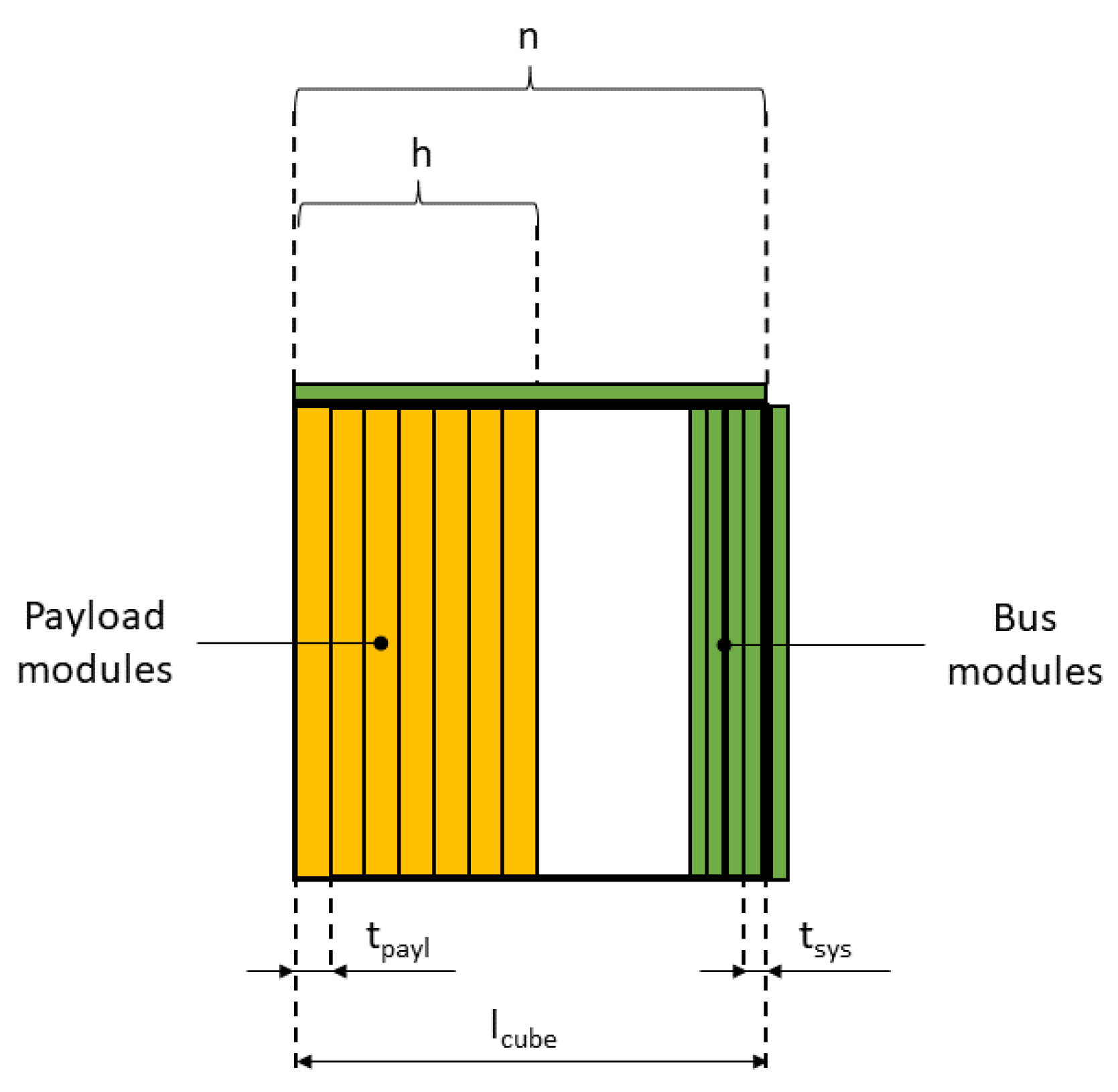
To evaluate the effectiveness of the smart tiles approach with respect to the amplitude of the design space A, a simple study case is considered. The following simplifying hypotheses, shown in Figure 4, are introduced:
1.
Different locations for the bus systems are considered. In the traditional solution, they are placed only in the internal volume of the satellite (except for small components like solar cells), while with a full smart tiles approach, they only occupy the external faces of the cube. Intermediate solutions are also considered, i.e., with part of the bus occupying the internal volume (for bulky components like reaction wheels) and part on the external faces (for thinner components like solar cells);
2.
The payload is hosted in the internal volume of the CubeSat only. This happens if the payload thickness is greater than 6.5 mm and cannot fit on the external faces (CubeSat mechanical requirement 3.2.3, [2] (p. 9)). Usually, the external faces are dedicated to the solar cells and to the electrical power system (EPS) and the payload is commonly located in the inside of the spacecraft. Possible reasons leading to choose an internal payload may be the payload delicacy or the protection from a thermal or radiation environment;
3.
The payload is composed of a set of modules with an equal, prismatic shape. The modules section is coincident with the cross-section of the internal volume of the CubeSat (in Figure 4, the payload modules are represented with the yellow boxes). This configuration is common for CubeSats payloads ([18] (p. 11), [19] (p. 4), [20] (p. 3)) and could represent a set of printed circuit boards (PCBs);
4.
A set of n payload modules is available. Due to internal volume restrictions, only h < n modules can fit in the payload bay;
5.
The n payload modules are independent. This means that they can operate independently and do not need to be connected to fulfill a single payload function.
The thickness of the payload modules t p a y l is between 6.5 mm and 18 mm, while for the bus modules, the thickness t s y s is fixed to 6.5 mm. Thus, the bus modules can either be stored in the internal volume or on the external faces. There are k smart tiles occupied by the bus subsystems, where k varies between 0 and 6.
From elementary combinatorics, the total number P of possible payload configurations is:
P = h ! n h = n ! ( n h ) !
The number of possible payload configurations P must be correlated with the amplitude of the payload design space A, i.e., it must be decided which is the function f at Equation (8). To respect the condition that A ( 1 ) = 0 (Equation (9)), it is assumed that f ( P ) = P 1 , and thus A = P 1 :
A = P 1 = n ! ( n h ) ! 1
It is useful to divide the amplitude A by the total volume of the payload V p a y l . The specific amplitude of the payload design space A * is thus obtained:
A * = A V p a y l = 1 V p a y l n ! ( n h ) ! 1
The study case considers a variable payload module thickness t p a y l . For each value of the thickness, the total number of payload modules n, from which the h < n modules are chosen, is taken as equal to the maximum number of modules that fit in the internal volume:
n = floor l c u b e t p a y l
The number of payload modules h stored in the CubeSat internal volume is computed accounting for the volume occupied by the 6 k bus modules:
h = floor l c u b e t s y s ( 6 k ) t p a y l
The payload volume V p a y l is obtained from the number of modules h:
V p a y l = h · l c u b e 2 · t p a y l
Finally, the total volume V C S of the CubeSat is evaluated adding the fixed internal volume V i n t with the volume occupied by the smart tiles V t i l e s :
V C S = V i n t + V t i l e s = l c u b e 3 + k l c u b e 2 t s y s
The volumetric efficiency of the CubeSat γ C S is also evaluated, using its definition at Equation (2). The equations above refer to the 1U form factor and can be easily adapted for the other form factors.
The results for the form factors 1U, 2U, 3U, and 6U are shown in Figure 5. The figure summarizes the advantages of the smart tiles approach applied to form factors 1U, 2U, 3U, and 6U. Figure 5a shows the total volumetric increments as a function of the total CubeSat volume V C S , for different numbers of tiles k. The maximum volume gain δ C S = γ C S 1 for the 1U case is 63.93% is obtained with six tiles. For the 2U, the same number of tiles leads to a lower value of 22.41%, for the 3U an even lower value of 13.52% and for the 6U just 8.12%. In general, the higher the internal volume of the CubeSat is, the lower the volume gain is for a fixed number of tiles k, as shown in the box on the left in the figure (Equation (2)).
These results suggest that the maximum advantage in terms of volumetric efficiency can be reached in the 1U case. Nevertheless, remarkable volume gains can be obtained for the 2U, 3U, and 6U cases, but this requires major efforts. For bigger CubeSats, more complex payloads can be carried and thus more types of tiles may be needed. In addition, more tiles would need to be built and tested.
Figure 5b represents the specific payload design space amplitude A * as a function of the total spacecraft volume V C S for various payload modules thicknesses t p a y l . It can obviously be concluded that bigger form factors have a wider payload design space. However, it is unusual for the 6U, for example, to have payloads whose thickness is under 10 mm, and thus the design space amplitude could be more comparable with the 3U form factor.
For smaller form factors (like 1U and 2U) it can be noticed that, although they are disadvantaged from the payload design space amplitude side, they tend to reach significant fractions of the maximum design space amplitude with fewer tiles. For example, in the case of a payload thickness of 6.5 mm and three tiles, the 1U reaches 19.44% of the maximum payload design space amplitude, while the 2U reaches just 0.02%. Significant fractions of the maximum amplitude can be reached with a remarkably major number of tiles, with respect to smaller form factors. An elevated number of tiles would have the disadvantages discussed above, making the smart tiles approach less effective. This again suggests that the smart tiles approach could be more effective with the smaller form factors, like 1U and 2U.

3. Embedded Battery Tile Design and Construction

The proposed smart tiles architecture has been shown to be effective from the point of view of volumetric efficiency (Section 2.1) and of the amplitude of the payload design space (Section 2.2).
However, an essential part of the tile development is its design and construction. In the present section, the prototype design is analyzed (Section 3.1) and the construction of components and the assembly procedure are described (Section 3.2).

3.1. Embedded Battery Tile Prototype Design

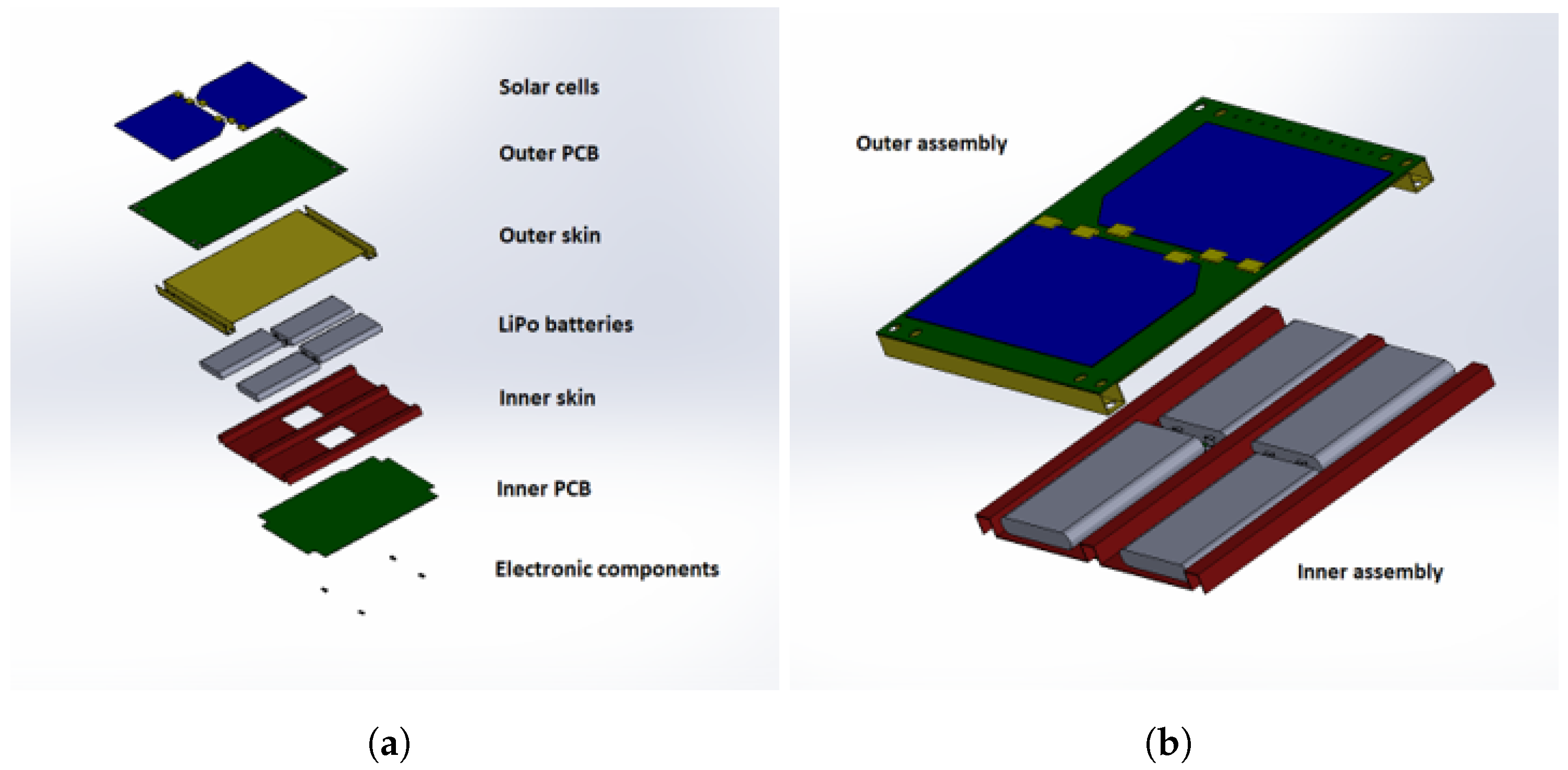
The proposed embedded battery tile prototype is shown in Figure 2 and Figure 6 and descends from the preliminary design work on modular multifunctional structures for CubeSats [21]. The configuration is inspired to advanced sailplanes wing boxes concepts [22]. Four lithium polymer (LiPo) batteries are enclosed between two CFRP skins, as shown in yellow and red in Figure 6a. The skins, besides contributing to the flexural and torsional stiffness of the tile, provide containment and protection to the batteries from the external thermal environment. The printed circuit boards (PCBs, as shown in green in Figure 6a) provide the necessary circuitry for the electrical power system. The batteries terminals are soldered to the inner PCB, and to allow the passage of the terminals, the inner skin has two rectangular holes. The outer PCB is placed in the external side of the tile and hosts two solar cells, while the inner PCB is placed on the internal side of the tile and hosts electronic components. The tile dimensions are 97.8 × 82.2 mm 2 .
The tile is joined to a commercial skeleton (Figure 1b) with two sets of four screws. The outer PCB and the outer skin have eight holes to allow the joining (Figure 2c and Figure 6), whose diameter is 3 mm. The employed set of four holes depends on which face of the skeleton the tile is mounted on.
The design requirements are slightly different from the ones for sailplane design. The main design requirement is the low cost requirement, typical for most CubeSat projects. Another relevant requirement, as mentioned in Section 2.1, is the maximum protrusion thickness of 6.5 mm (CubeSat mechanical requirement 3.2.3 [2] (p. 9)), imposed by the CubeSat form factor. The requirements led to the following design solutions:
  • Low level of structural integration. As mentioned in the introduction section, a low level of structural integration between the energy storage components and the structural components was selected. Functional separation is still present in the design at a component level, between the components that implement the energy storage function and the components that implement the structural function. The electrical power system components can be clearly identified and isolated from the structural components. Nevertheless, the whole battery tile assembly performs both the energy storage and the structural function. This is known in the literature as the first degree of structural integration [12] (pp. 3–4). Superior degrees of integration introduce an increasing component-level functional integration, up to the microscopic scale. Although these degrees of integration are not applicable with a low-cost design, they would allow a considerable mass and volume optimization. They could be considered for a very high performance, non-low-cost solutions;
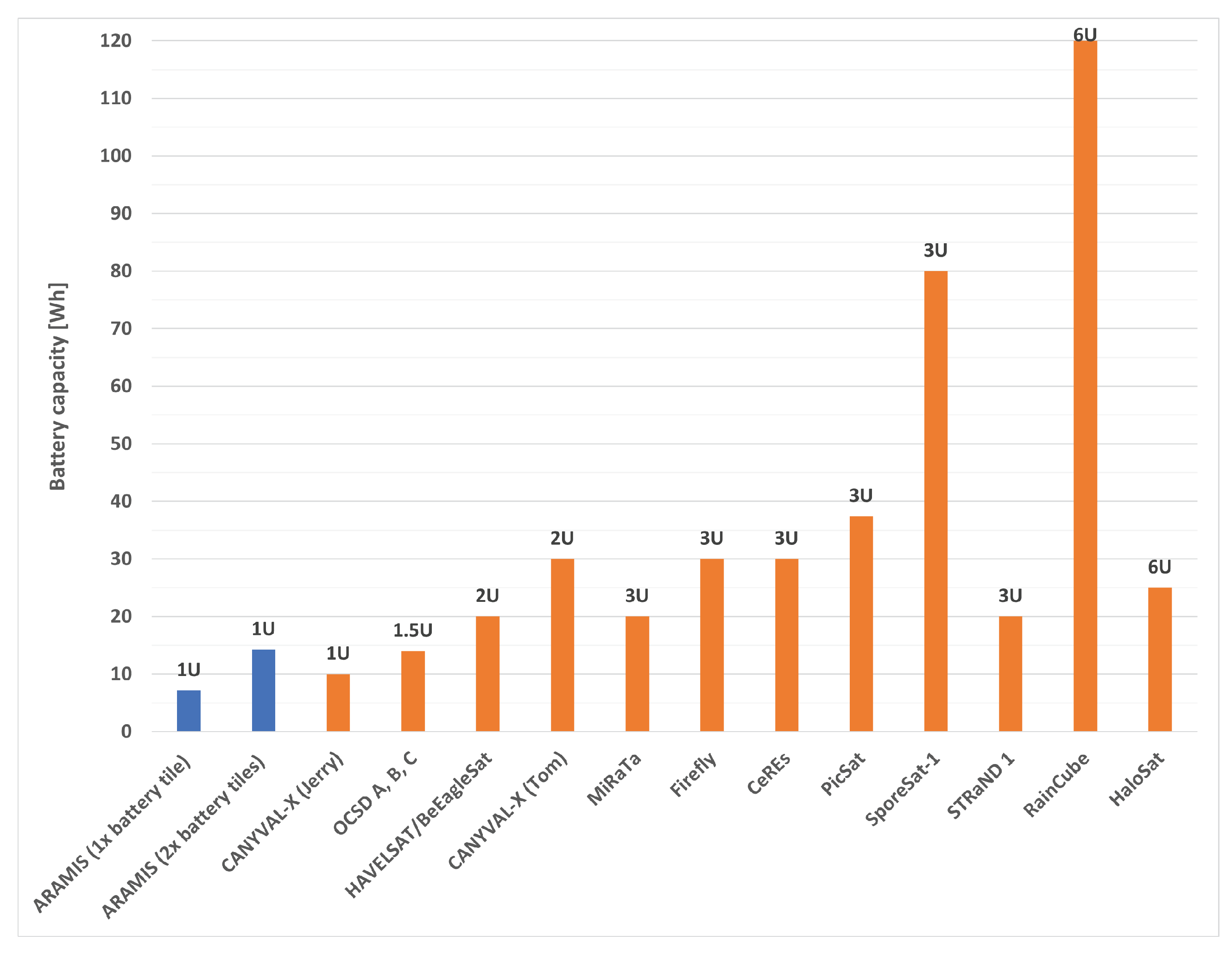
  • Lithium polymer (LiPo) batteries. COTS Lithium Polymer batteries were selected based on their energy capacity and dimensions, considering the energy capacity of state-of-the-art CubeSats (Figure 7). The maximum protrusion of 6.5 mm was relevant in the selection of the battery model. LiPol LP452540 batteries were selected [23], with a nominal charge capacity of 480 mAh at 3.7 V, and thus a single battery capacity of 1.78 Wh. Four batteries were mounted on the embedded battery tile, with a total tile capacity of 7.12 Wh. This electrical energy capacity is slightly inferior to the typical capacity of state-of-the-art 1U CubeSats (Figure 7). However, since the smart tiles are modular, two or more embedded battery tiles can be mounted on the skeleton. With two battery tiles, the CubeSat capacity grows to 14.2 Wh, which is more than typical 1U satellites and comparable to the 1.5U typical capacity (14 Wh);
  • Carbon fiber (CFRP) skins. Due to the aforementioned limitations on the total tile thickness, the two CFRP skins layup consists of a single layer of 2 × 2 twill-weave-woven carbon fabric. The layup sequence is [ ± 45 ] . The CFRP material is a commercial prepreg material system and belongs to the family of the Toray/Huntsman T300/LY 564 [24,25]. Standard mold forming and autoclave curing procedures were adopted and are described below;
  • Printed circuit boards (PCBs). The electrical power system circuitry is hosted on two COTS PCBs. The thickness of the inner PCB is 0.75 mm and the thickness of the outer PCB is 0.44 mm. From a structural point of view, the boards can be modeled as plates composed of continuous layers of copper and epoxy resin.

3.2. Embedded Battery Tile Prototype Construction

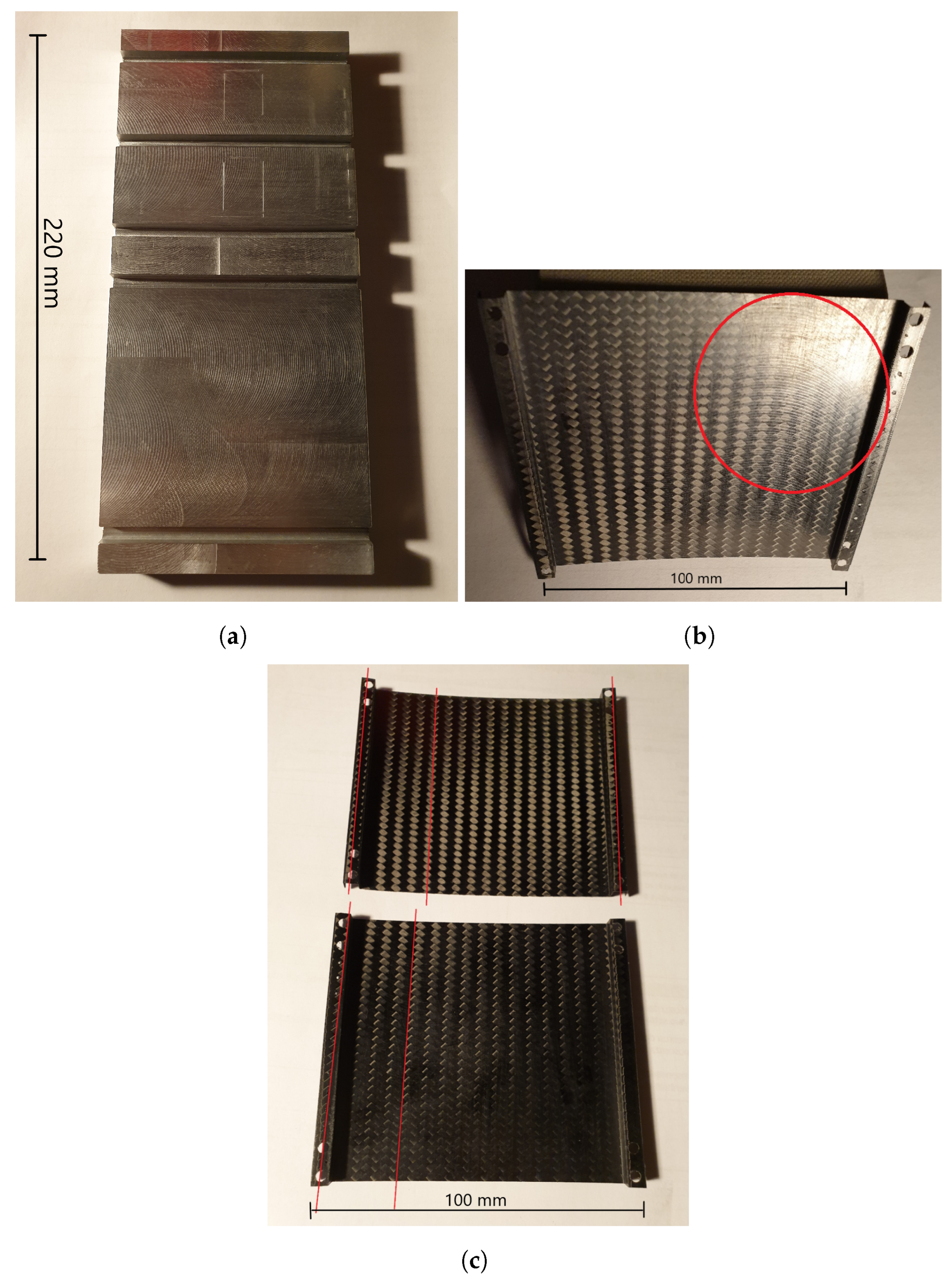
The production cycle of the CFRP skins consists of a manual layup and autoclave curing. Although traditional and consolidated techniques have been employed, the reduced dimensions of the skins made the process technologically complex. An aluminum mold was obtained by milling a solid aluminum panel (Figure 8a). The manual layup of the prepregs was then performed, and the assembly of mold and prepregs was vacuum-bagged. An autoclave cure cycle with a polymerization phase of 90 min at 120 °C was set up, with thermal ramps of 3 °C per minute. The milling of the aluminum panels left circular traces on the mold, that have been also imparted to the CFRP skins (as shown within the red circle in Figure 8b).
Dimensional checks have been performed on the skins. Their dimensions are within the tolerance of 0.1 mm, although some defects were noticed. The angle of the fibers has slight deviations of up to 1° from the nominal angle of ±45°. Figure 8c shows the alignment defect with red lines following the fabric. This defect can be caused by the distortion imposed on the prepreg with the manual layup operation. An undesired cylindrical curvature was noticed in the central section of the skins (Figure 8b) and has been verified with a laser displacement acquisition system. The skins’ thickness was measured with an ultrasonic thickness gauge, and the mean thickness for all the skins was found to be 0.23 mm.
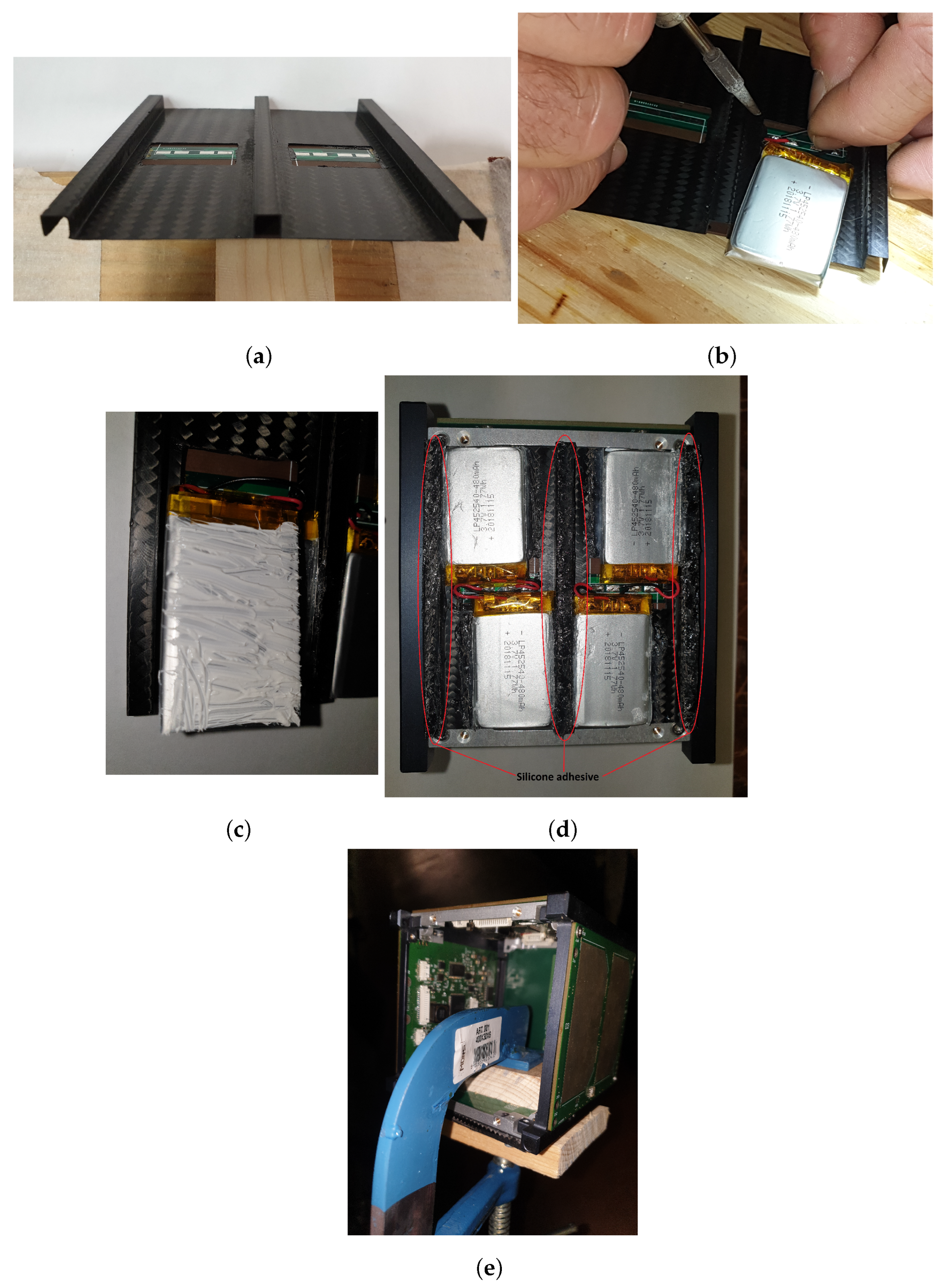
The prototype assembly sequence is shown in Figure 9. First, the PCBs and the CFRP skins have been glued to form the inner and outer assemblies (Figure 6b). The inner assembly prototype is shown in Figure 9a. The gluing has been made with the Elan-tech® ADH 971.961 epoxy adhesive. The polymerizations were performed at room temperature. Then, the batteries terminals were soldered to the inner PCB connections pads (Figure 9b). The batteries’ protection circuits, wrapped in the orange kapton tape in the figure, were not removed for electrical security reasons. The TermoPasty® thermal conductive paste H was spread on the surfaces of the batteries in contact with the Inner Skin (Figure 9c). Then, a commercial silicone adhesive was applied to the sides of the batteries (Figure 9d) as a structural joint. The same silicone adhesive was applied to the inner skin stiffeners to join the inner and outer assemblies. Finally, the subassemblies were mounted on the commercial CubeSat frame to ensure the mechanical compatibility of the whole spacecraft (Figure 9e).
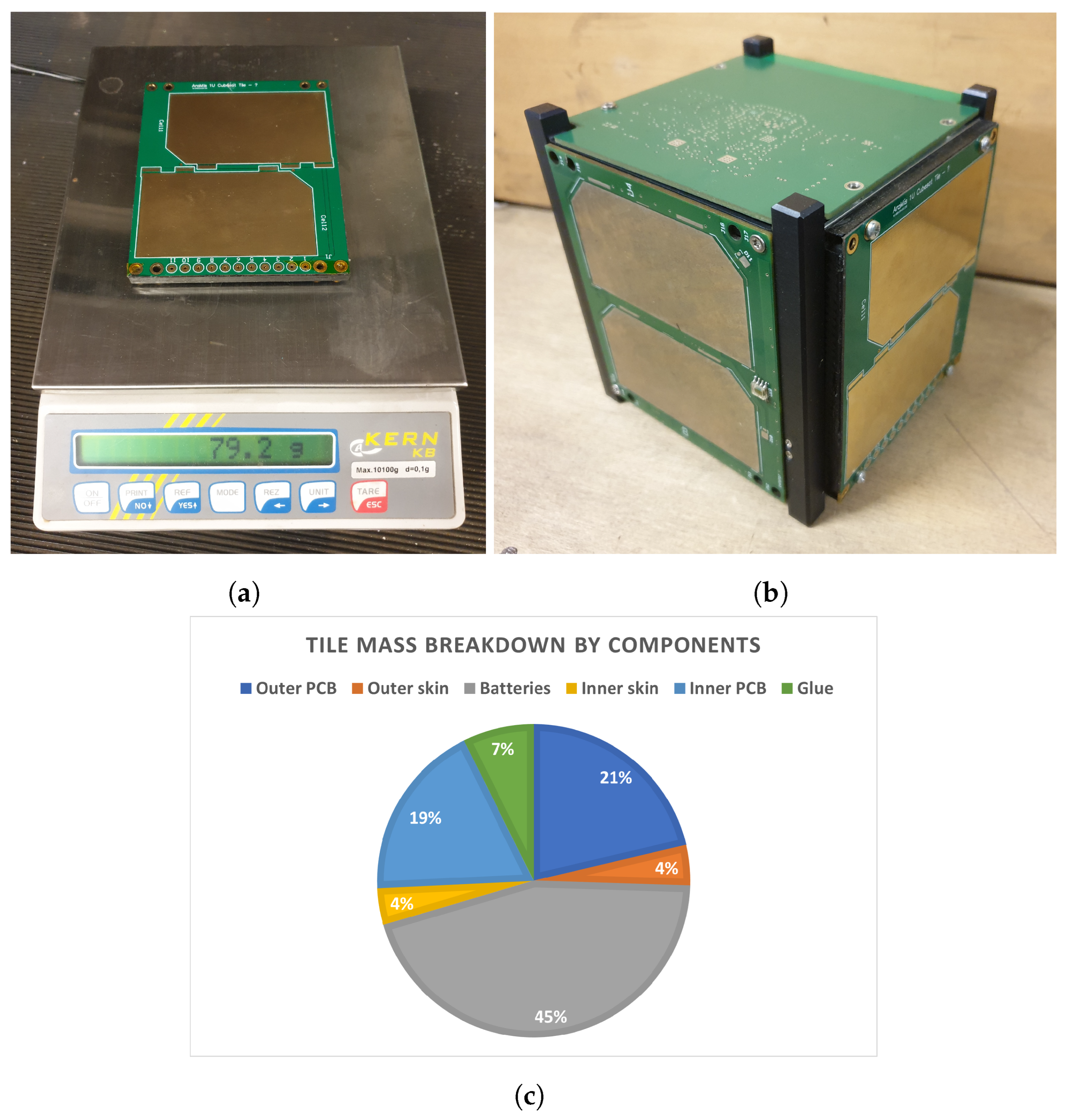
The final results of the assembly procedure are shown in Figure 10. The prototype is shown in Figure 10a. The measured thickness of the tile from the plane of the rails (Figure 1a) is 5.37 mm. This thickness does not include the solar cells. For the CAD model, the thickness is 5.24 mm, comparable to the real case. Accounting for the glued solar cells with their electrical connectors (shown in yellow in Figure 2c and Figure 6b), the CAD model has a protrusion of 5.87 mm from the plane of the rails. The aforementioned CubeSat mechanical requirement 3.2.3 ([2] (p. 9)) on the maximum protrusion of the tile from the plane of the rails is thus met.
For the structural mass ratio, it has been shown that the use of CFRP can reduce the 1U primary structure mass to 104.5 g [9] (p. 9). If the maximum total mass for a 1U is considered, 1.33 kg [2] (p. 9), the structural mass ratio is 7.8%. For the proposed multifunctional smart tile, the total mass of the tile is 79.2 g (Figure 10a) and the single battery mass is 8.9 g ( m B A T T , Figure 10c). If the mass of the solar cells, 2.3 g, is added, a total mass of 83.8 g is found. To be conservative, a value of 85 g is adopted ( m B A T T T I L E ). The mass of the aluminum skeleton is 87.2 g (https://www.isispace.nl/product/1-unit-cubesat-structure/, accessed on 12 August 2022) ( m S K E L ). The mass of other ARAMIS PCB tiles is 16.9 g, that is rounded to 17 g to be conservative ( m P C B T I L E ). This leads to the following extreme cases of structural mass ratios (SMRs):
  • One embedded battery tile and five PCB tiles ( N = 1 , M = 5 ):
    S M R = N · m B A T T T I L E n B A T T m B A T T + M · m P C B T I L E + m S K E L m M A X = = 1 · 85 4 · 8.9 + 5 · 17 + 87.2 1330 = 16.7 %
  • Six embedded battery tiles ( N = 6 , M = 0 ):
    S M R = N · m B A T T T I L E n B A T T m B A T T + M · m P C B T I L E + m S K E L m M A X = = 6 · 85 4 · 8.9 + 87.2 1330 = 28.8 %
where m M A X is the aforementioned maximum mass for a 1U CubeSat and n B A T T is the number of batteries in the embedded battery tile. These values are major than the mass ratio of the CFRP primary structure found in the literature of 7.8% [9] (p. 9). However, the proposed structure includes multifunctional aspects that are not included in the literature example. This implies that functional materials such as copper are employed, with a considerably higher mass density with respect to CFRP, and they must be added to the structural mass since they are part of the CubeSat structure.
The total mass of the prototype, including solar cells (85 g), can be compared with equivalent commercial systems having a comparable architecture. The Crystalspace P1U module (https://www.cubesatshop.com/product/crystalspace-p1u-vasik/, accessed on 8 September 2023) provides a power supply, with a mass of 80 g and an electrical power storage of 11 Wh (slightly superior to the prototype energy of 7.12 Wh). To compare this mass with the mass of the prototype, the mass of a solar panel assembly must be added, for example, the SM-SP1Z 1U Cubesat Z Solar Panel (https://satsearch.co/products/npcspacemind-sm-sp1z, accessed on 8 September 2023) (24 g). The mass of this assembly (104 g) is superior to the mass of the prototype that has similar performance, although commercial equipment is generally at higher development stages (in this example, the power storage module is flight-proven). Moreover, the proposed prototype has the advantages of saving internal volume for the payload and of providing more protection and containment to the batteries.
Finally, a fit check was performed to ensure the mechanical compatibility of the prototype with the commercial CubeSat frame (Figure 10b). The total measured mass of 79.2 g (Figure 10a), broken down by components, is represented in Figure 10c. From the point of view of the mass, the design can be considered effective, since the batteries make up 45% of the total mass. The outer PCB and the inner PCB, that make up 21% and 19% of the total mass, respectively, should also be considered as part of the structure, since they contribute in some measure to the overall rigidity of the tile.

4. Embedded Battery Tile Modal Testing

The experimental modal analysis of the embedded battery tile prototype is evidently challenging for the small dimensions (Figure 6 and Figure 8) and mass of the system (Figure 10), with the inner skin weighing only 3.0 g. It has been performed to verify the suitability of the components’ manufacturing processes and of the assembly sequence (Section 3.2). In addition, the compatibility with several launch vehicles has been verified [26,27,28].
Section 4.1 outlines what motivated the choice of the experimental setup and describes it in detail, and Section 4.2 describes the search for adequate locations on the samples for actuators, which proved to be a critical aspect. Section 4.3 describes the established experimental procedure, and finally, Section 4.4 illustrates the main results.

4.1. Experimental Setup

The excitation of the structural samples must not alter the dynamics of the sample itself. For this reason, a careful selection of the excitation method has been made [29] (pp. 174–194). Miniaturized piezoelectric actuators were chosen thanks to their low mass and the consequent low level of interference. A scanning laservibrometer was chosen as a transducer, totally avoiding any contact with the sample. The complete setup is shown in Figure 11.
A schematic of the setup is shown in Figure 11a. The piezoelectric actuator is a custom-made PI Ceramic PRYY+0412. It has an outer diameter of 10 mm, a thickness of 0.2 mm, and silver electrodes (Figure 11b). The actuator’s active material is a PIC255 ceramic piezoelectric material that belongs to the family of lead zirconate titanate (PZT). The first resonance frequency of the piezoelectric actuators is well above the expected frequency range of interest of the targets. The actuators were glued at room temperature to the targets with a cyanoacrylate commercial glue. To avoid any interference due to uncertainties in the boundary conditions, the target is suspended with a fixing system to the testing frame to obtain a condition that is as close as possible to the perfectly free condition (Figure 11c).
The testing frame’s first resonance frequency is outside of the expected frequency range of interest of the targets. The testing frame firmly clamped on the working table. The laservibrometer is a Polytec PSV500 scanning vibrometer (Figure 11d). The scanning head generates a laser beam whose wavelength is 633 nm and is mounted on a tripod. The tripod has been positioned to have a horizontal laser beam that hits the target. The front end is connected to a laptop and allows the setting of the experiment parameters and the postprocessing of the results.
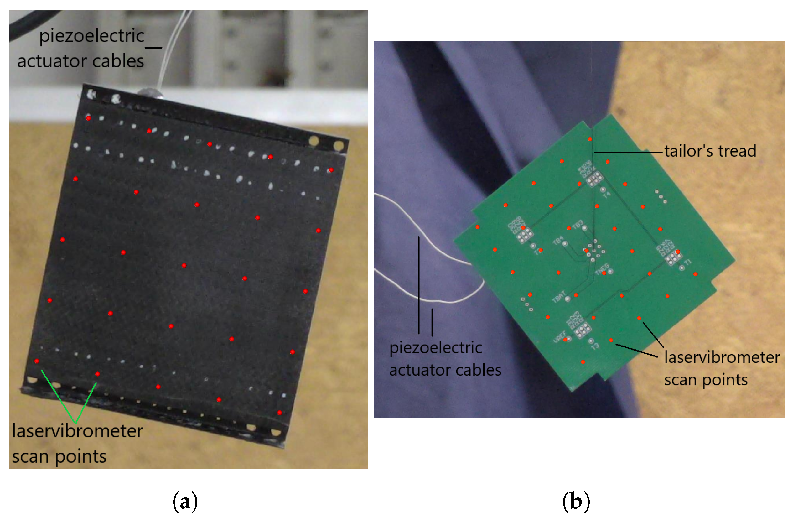
Various components and configurations for the fixing system have been tested. Commercial rubber bands, cable ties, and tailor’s treads were employed. Figure 11c and Figure 12 depict the final configurations for each target. The fixing system was not employed for the CFRP skins due to their reduced mass (3.3 g for the outer skin and 3.0 for the inner skin, as shown in Figure 12a). The constraint is given by the electrical cables of the piezoelectric actuator. The tailor’s tread was selected for the experimental setup of PCBs (Figure 12b) and of the entire tile. In these cases, the soldering between the electrical cables and the piezoelectric actuator could not withstand the mass of the samples. Cable ties and rubber bands were chosen for the aluminum panel (Figure 11c).

4.2. Design of Experiment—Actuator Locations

A critical aspect of the experimental setup is the location of the piezoelectric actuators on the targets. This location must be carefully chosen to obtain an acceptable level of excitation of the first and the second free–free modes of the targets at least. Thus, a preliminary investigation was made. For each target, the set of possible actuator positions was chosen based on the first three mode shapes. All possible configurations were tested with an MSC NASTRAN SOL 111 frequency response model. An analogy between the piezoelectric effect and the thermal effect was exploited [30] to model the excitation of the actuators.
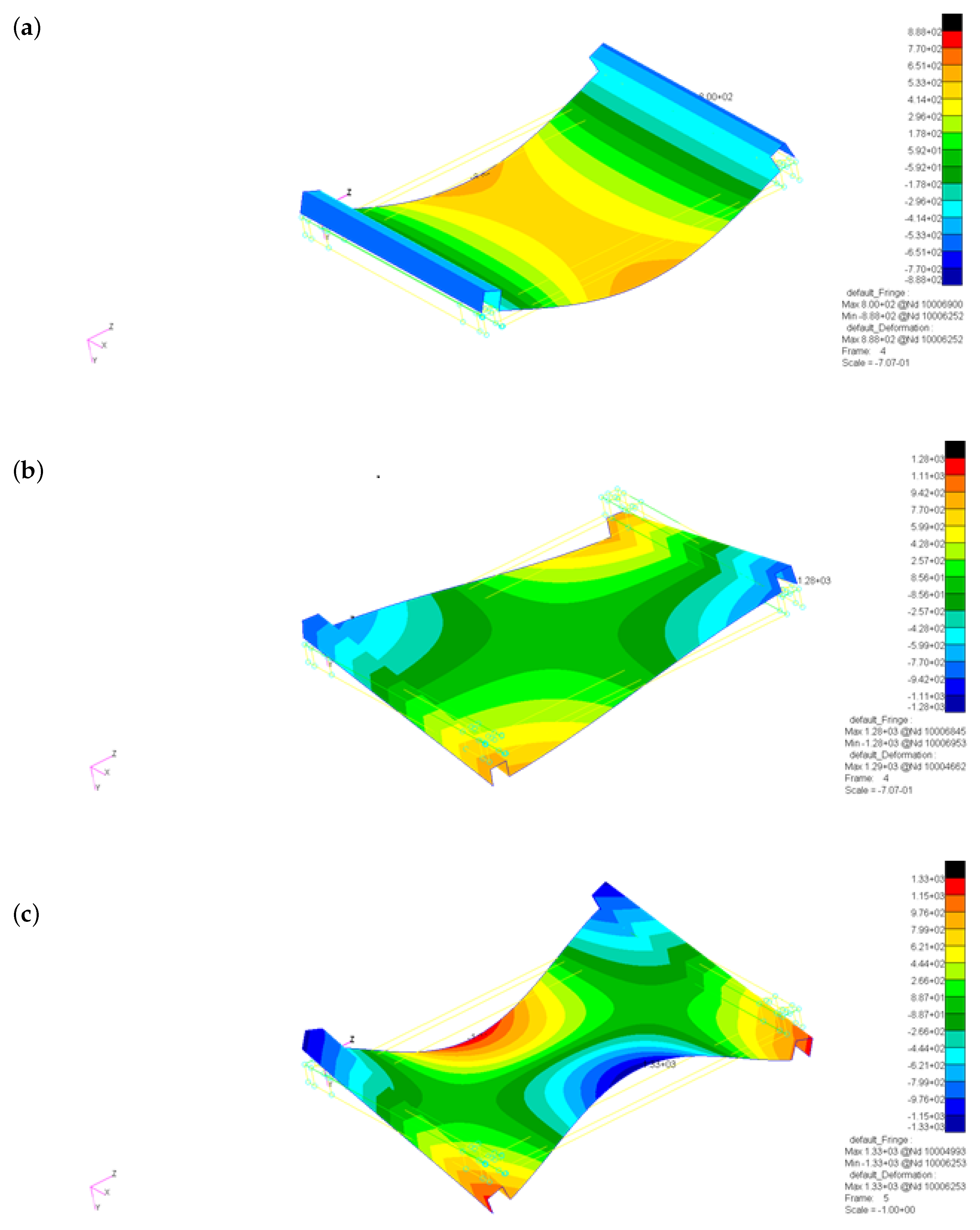
As an example, the outer skin case is presented (Figure 13). The first three structural modes are identified with a linear modal analysis and free boundary conditions. The eigenfrequencies and the mode shapes are shown, respectively, in Table 2 and Figure 13a.
Given the mode shape symmetry, two configurations were considered (Figure 13b). For configuration 1, the actuator is on the central, flat portion of the skin, while in configuration 2, the actuator is on the rib of the skin. The SOL 111 analysis was performed on the outer skin model to choose the best experimental configuration. The excitation voltage in this case has a constant amplitude from 0 Hz to 600 Hz. For the results, the nodes depicted in Figure 13c were considered. The results are shown in Figure 14. With configuration 1, it is very difficult to appreciate mode 7, while modes 8 and 9 are much more excited and are thus well visible. The results for configuration 2 instead indicate that all three modes 7–9 are well excited, but to a level which is slightly inferior to the one of modes 8 and 9 for configuration 1. However, configuration 2 is chosen as the best experimental configuration.
The printed circuit boards have been treated in a similar manner. From a mechanical point of view, PCBs are a laminate composed of several layers of Flame Retardant-4 (FR-4) and copper. The FR-4 is approximated as an isotropic material, although it may have randomly dispersed glass fibers in a matrix of epoxy resin. The lamination for the PCBs is taken from the electronic board project files developed with the Altium Designer (6.0 in 2005) software.

4.3. Test Procedure

The experimental setup described above has been exploited to determine the mechanical characteristics of the tile components and to determine their modal properties. As a preliminary step, a verification of the chosen experimental procedure with an aluminum panel (Figure 11b–d) was performed. Once the procedure was found to be valid, the tile components were analyzed and finally the entire tile was analyzed. The steps of the experimental procedure are the following:
1.
Correction of the mass density. The mass of each component has been measured and the density of the component in the numerical model was corrected to match the measured density. For the tile model, the mass of the epoxy and siliconic resin was neglected since the difference between the experimental mass and the numerical model mass (only due to the components) is below 10%;
2.
Correction of mechanical properties—a linear modal analysis (SOL 103) was performed with the numerical models of the components. The modal analysis is conducted with free boundary conditions. The mechanical properties of the materials, i.e., aluminum, FR-4, copper, and CFRP were corrected to match the eigenfrequencies with the experimental data from the laser vibrometer, taking into account the correction of the mass density. For the complete tile model, the mechanical properties of the LiPo batteries were corrected to match with the experimental data;
3.
Extraction of the experimental and numerical modes. For each component, the data from the relevant modes (at most the first five modes) were collected from the experimental and numerical results;
4.
AutoMAC of experimental and numerical modes. To verify the correctness of the experimental measurements and of the numerical analyses, for each sample, an autoMAC was performed on the experimental modes and on the SOL 103 modes;
5.
CrossMAC between experimental and numerical modes. Once the autoMAC step was completed, a crossMAC was performed between the experimental and the SOL 103 data [31];
6.
Comparison between experimental and numerical frequency response spectra (SOL 111). Finally, a comparison between the experimental response spectra and the numerical spectra was performed. For the frequency response numerical analysis, the voltage input is the experimental voltage input given to the piezoelectric actuators. The numerical analysis considers the electrical cables of the piezoelectric actuator and not the tailor’s tread of the fixing system. The modal dampings of each target have been extracted from experimental data. The mean spectra are considered, i.e., the arithmetic averages of spectra at each measurement point.

4.4. Results and Discussion

The application of the experimental procedure described above led to the materials’ mechanical properties given in Table 3. These properties allow the correlation with the experimental data in terms of components and complete tile eigenfrequencies, modal shapes, and frequency response spectra, as shown in the present section.
The properties for CFRP are in line with common woven CFRP materials [32,33]. For the batteries, the mechanical properties are found by matching the modal analyses results with the experimental results and the entity of the Young’s modulus is compatible with previous studies [34] (p. 316).
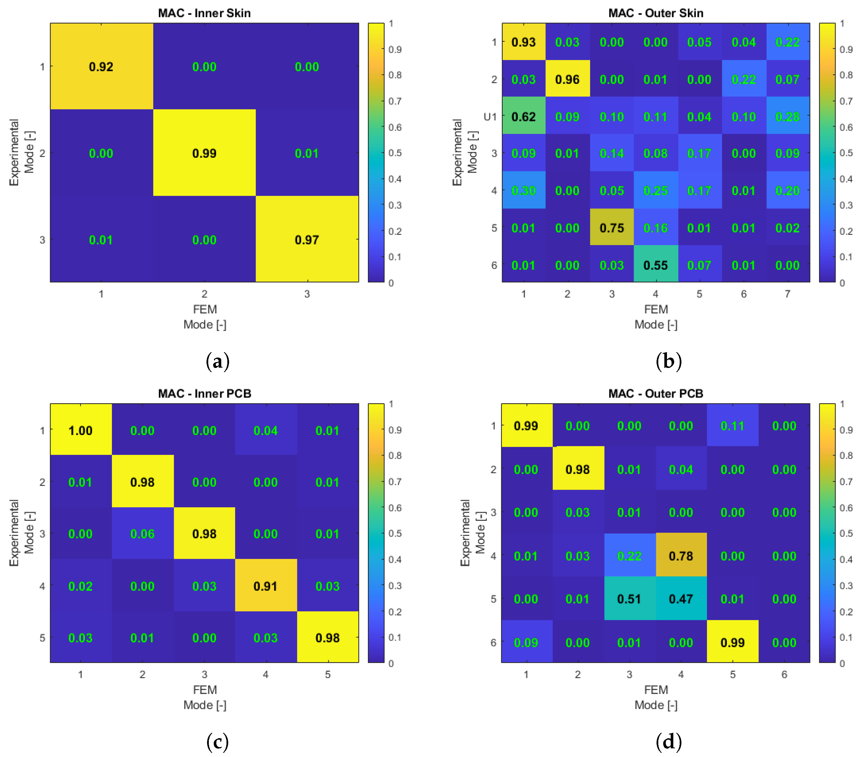
The comparison between experimental and SOL 103 eigenfrequencies for the tile components is given in Table 4, where the relative difference Δ is given in percentage in the rightmost column. The corresponding crossMAC analysis results are given in Figure 15.
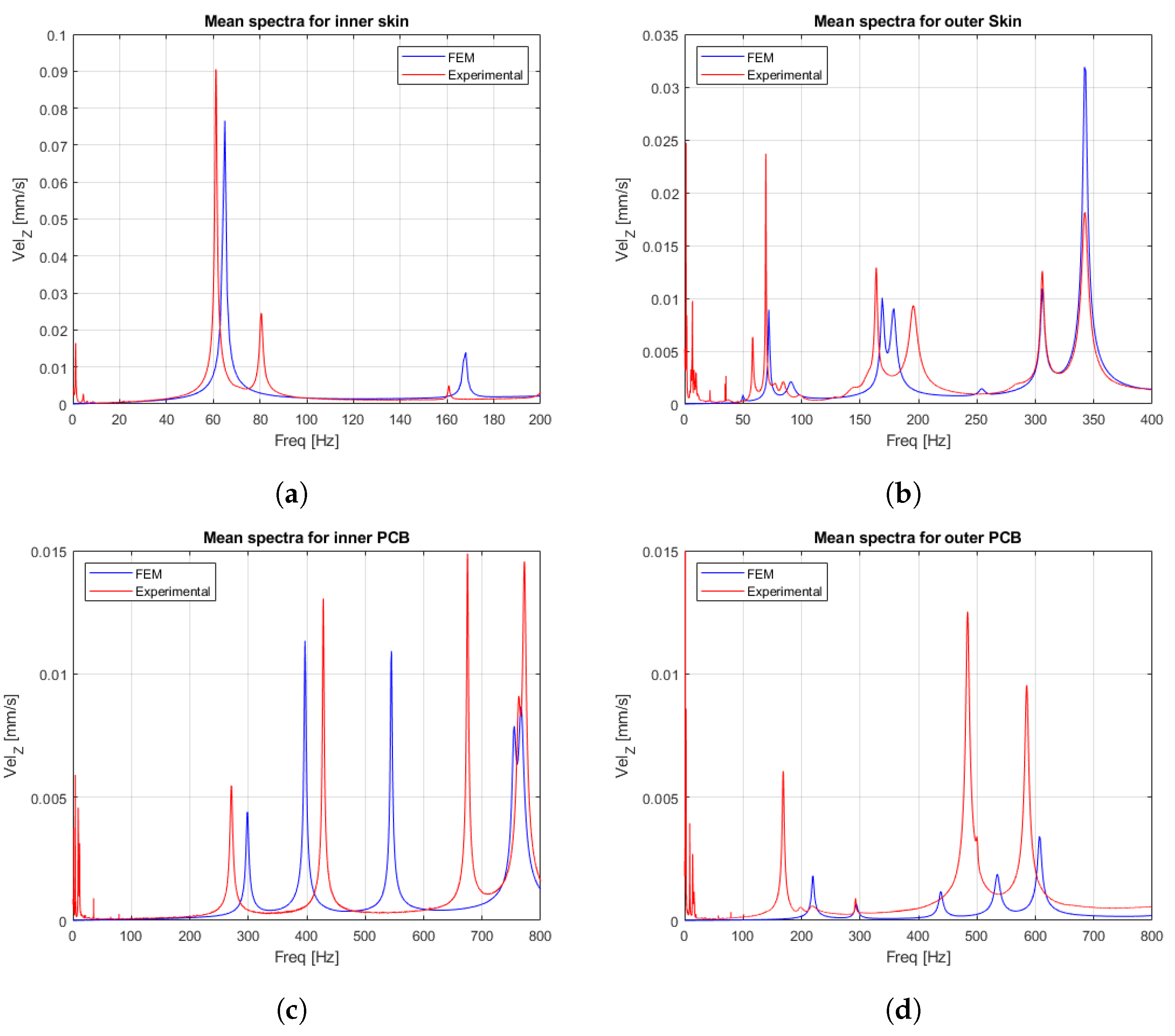
For the inner skin, the correlation between the experimental and numerical eigenfrequencies is acceptable. The crossMAC analysis (Figure 15a) confirms the correspondence between the numerical and experimental mode shapes. For the outer skin, while experimental modes 1–3 have a good correspondence with the numerical modes in terms of eigenfrequencies, the experimental mode at 84.25 Hz has no clear correspondence with the numerical modes. This is due to the interference of the piezoelectric actuator cables (Figure 12a), which induce a constraint that is not considered in the free–free numerical analysis. The mode appears in the mean frequency response spectra (Figure 16b) that takes into account the constraint. The crossMAC analysis (Figure 15b) could find an acceptable match between the experimental and numerical mode shapes just for modes 1 and 2.
For the inner PCB, the eigenfrequencies (Table 4) show a good correlation between experimental and numerical data, except for mode 3. This may be due to the fixing system of the experimental setup. The tailor’s tread, in this case, exploits a through hole near the center of the PCB (Figure 12b), that is, the maximum displacement point of the third modal shape. The experimental mode frequency is then altered, although the correlation between the experimental and the numerical modal shapes is acceptable with a crossMAC of 98% (Figure 15c). For the outer PCB, the linear modal analysis reveals a good correlation between the eigenfrequencies with the experimental data, except for the first mode. This again may be due to the interference from the fixing system. The explanation is the same as in the inner PCB case. The fixing system has interfered with the first modal shape and thus the experimental eigenfrequency is rather different, although the modal shapes have a crossMAC of 99% (Figure 15d).
The crossMAC (Figure 15d) reveals that there is no correlation between the experimental mode shape 3 and the numerical mode shape 3.
The mean frequency response spectra for the tile prototype components are presented in Figure 16. For the inner skin (Figure 16a), the experimental data show a considerable noise below 20 Hz. The first mode is reproduced in the FEM result with acceptable precision. The second mode is visible in the experimental spectrum while it is not visible in the numerical analysis due to the piezoelectric actuator location. In the case of the outer skin (Figure 16b), the experimental data show much noise below 50 Hz. The amplitudes for modes 1 and 2 are much higher than for the numerical data obtained with the experimental voltage input. For the PCBs (Figure 16c,d), the results exhibit considerable noise below 100 Hz. The Inner PCB spectra (Figure 16c) reflect the discrepancy between the experimental and numerical eigenfrequencies of the third mode (Table 4). Similarly, the outer PCB spectra (Figure 16d) reflect the discrepancy between the first experimental and the first numerical eigenfrequency, as shown in Table 4. This is due to the absence of the tailor’s tread in the SOL 111 simulation.
The structural modes for the complete tile prototype are shown in Figure 17. The upper row shows the experimental modes and the lower row shows the correspondent SOL 103 modes. The FEM eigenfrequencies (Table 5) have a good compatibility with the experimental frequencies, up to the third mode. The discrepancies for the fourth and fifth modes can be due to inaccuracies in the assembly procedure and approximations in the FEM model; however, the FEM model is considered acceptable.
The crossMAC between the experimental and numerical data (Figure 18a) gives an acceptable match just for the first and the second mode. Thus, the eigenfrequency match for the third mode (Table 5) should be considered with caution. The mean spectra (Figure 18b) show good correspondence just for the first and the second mode. There is a remarkable component of experimental noise below 200 Hz.
In conclusion, although just the first and the second mode have acceptable results, the results of the complete tile analysis are considered acceptable. In fact, usually the launch vehicle requirements are given just on the first eigenfrequencies. The modal characteristics of the tile prototype are compatible with the Vega [26] (pp. 4–3, 4–4), Ariane 6 [27] (p. 4–4), Falcon 9 and Heavy [28] (p. 17) launch vehicle requirements.

5. Conclusions

The present work aims to develop the current CubeSats architecture from the typical “cube structure with a stack of circuit boards inside” [4] (p. 7). The concepts of the CubeSat volumetric efficiency (Section 2.1) and the amplitude of the payload design space (Section 2.2) are introduced and the methods for their quantification in the CubeSats preliminary design phase are developed. In Table 1, it is shown that the CubeSat volumetric increment can reach 36.97% with the use of six smart tiles that have the same volumetric efficiency of the embedded battery tile prototype. It is shown that the multifunctional smart tiles approach is advantageous from these points of view. The advantage is major for the smaller form factors 1U and 2U with respect to the bigger form factors 3U and 6U. The structural mass ratio of the 1U CubeSat (Section 3.2) varies with the smart tiles configuration and is shown to be between 16.7% and 28.8%.
The design of an innovative 1U CubeSat smart tile, employing lightweight, composite materials in multifunctional structures was performed (Section 3.1). The construction of the prototype (Section 3.2) proved that the design is technologically feasible with a traditional autoclave curing of CFRP commercial prepregs, although CFRP components are miniaturized and ultrathin.
A new experimental procedure for the modal testing of miniaturized, ultralight, and ultrathin CubeSat components has been defined (Section 4.1). The test procedure and experimental setup proved suitable for the modal testing of miniaturized CFRP components, printed circuit boards, and smart tiles, up to a minimum mass of 3.0 g and a minimum thickness of 0.23 mm. The results for the entire embedded battery tile (Section 4.4) showed a good correlation between the experimental results and the numerical results for the first and the second eigenmodes. The modal characteristics of the prototype are compatible with the Vega [26], the Ariane 6 [27], the Falcon 9, and the Falcon Heavy [28] launch vehicles. Therefore, the proposed design for the embedded battery tile is adequate from the point of view of the modal behavior.
In conclusion, the results of the present work for the embedded battery tile are encouraging, and the employment of multifunctional structures and lightweight, composite materials is shown to be advantageous for nanosatellites. CubeSat designers may benefit this type of space structures either by adopting smaller form factors, thus saving launch costs with the same mission objectives, or by designing more sophisticated missions, able to reach more ambitious and complex mission objectives saving a significant amount of volume and mass for the payload.
Finally, the applications of the presented results on structural batteries are promising for future electric or fuel cell aircrafts. The proposed embedded battery tile design could be adapted to fit into the wing structures of electric aircrafts. The requirements may be significantly different, but the design philosophy would be the same. Structural batteries can be beneficial to uninhabited aircrafts but also to inhabited aircrafts [35,36].

Author Contributions

Conceptualization, G.C., E.C. and L.R.; methodology, G.C., E.C. and L.R.; software, G.C. and E.C.; validation, G.C., E.C. and L.R.; formal analysis, G.C. and E.C.; investigation, G.C., E.C. and L.R.; resources, E.C. and L.R.; data curation, G.C.; writing—original draft preparation, G.C., E.C. and L.R.; writing—review and editing, G.C., E.C. and L.R.; visualization, G.C., E.C. and L.R.; supervision, E.C.; project administration, G.C., E.C. and L.R. All authors have read and agreed to the published version of the manuscript.

Funding

This research received no external funding.

Acknowledgments

The authors would like to thank professor Giulio Romeo for his support and advice.

Conflicts of Interest

The authors declare no conflict of interest.

References

  1. Nanosats Database. Available online: www.nanosats.eu (accessed on 4 March 2023).
  2. The CubeSat Program. Cubesat Design Specification Rev. 13. Technical Report. 2014. Available online: https://static1.squarespace.com/static/5418c831e4b0fa4ecac1bacd/t/56e9b62337013b6c063a655a/1458157095454/cds_rev13_final2.pdf (accessed on 4 March 2023).
  3. The CubeSat Program. 6U Cubsat Design Specification, Revision 1.0. Technical Report. 2018. Available online: https://static1.squarespace.com/static/5418c831e4b0fa4ecac1bacd/t/5b75dfcd70a6adbee5908fd9/1534451664215/6U_CDS_2018-06-07_rev_1.0.pdf (accessed on 4 March 2023).
  4. Heidt, H.; Puig-Suari, J.; Moore, A.; Nakasuka, S.; Twiggs, R. CubeSat: A new Generation of Picosatellite for Education and Industry Low-Cost Space Experimentation. In Proceedings of the 14th Annual/USU Conference on Small Satellites, Logan, UT, USA, 21–24 August 2000. [Google Scholar]
  5. Wang, X.; Zhang, S. Cost analysis for mass customized production of satellites based on modularity. IEEE Access 2021, 9, 13754–13760. [Google Scholar] [CrossRef]
  6. Areda, E.; Cordova-Alarcon, J.; Masui, H.; Cho, M. Development of Innovative CubeSat Platform for Mass Production. Appl. Sci. 2022, 12, 9087. [Google Scholar] [CrossRef]
  7. Kenyon, S.; Bridges, C.P.; Liddle, D.; Dyer, R.; Parsons, J.; Feltham, D.; Taylor, R.; Mellor, D.; Schofield, A.; Linehan, R. STRaND-1: Use of a $500 Smartphone as the Central Avionics of a Nanosatellite. In Proceedings of the 62nd International Astronautical Congress, Cape Town, South Africa, 7 October 2011; Available online: https://openresearch.surrey.ac.uk/esploro/outputs/99511792602346 (accessed on 1 July 2023).
  8. Koo, K.; Kim, H.; Dong-Geon Kim, D.; Kwon, S.; Oh, H. Lightweight Design for Active Small SAR S-STEP Satellite Using Multilayered High-Damping Carbon Fiber-Reinforced Plastic Patch. Aerospace 2023, 10, 774. [Google Scholar] [CrossRef]
  9. Ampatzoglou, A.; Baltopoulos, A.; Kotzakolios, A.; Kostopoulos, V. Qualification of Composite Structure for Cubesat Picosatellites as a Demonstration for Small Satellite Elements. IJASAR 2014, 1, 1–10. Available online: https://scidoc.org/articlepdfs/IJASAR/IJASAR-2470-4415-01-101.pdf (accessed on 1 July 2023).
  10. Asp, L.E.; Johansson, M.; Lindbergh, G.; Xu, J.; Zenkert, D. Structural battery composites: A review. Funct. Compos. Struct. 2019, 1, 042001. Available online: https://iopscience.iop.org/article/10.1088/2631-6331/ab5571/pdf (accessed on 4 March 2023). [CrossRef]
  11. Thomas, J.P.; Qidway, M.A.; Pogue, W.R., III; Rohatgi, A. Multifunctional structure-battery composites for marine systems. J. Compos. Mater. 2013, 47, 5–26. [Google Scholar] [CrossRef]
  12. Adam, T.J.; Liao, G.; Petersen, J.; Geier, S.; Finke, B.; Wierach, P.; Kwade, A.; Wiedemann, M. Multifunctional composites for future energy storage in aerospace structures. Energies 2018, 11, 335. [Google Scholar] [CrossRef]
  13. Hwang, J.T.; Young Lee, D.; Cutler, J.W.; Martins, J.R.R.A. Large-scale multidisciplinary optimization of a small satellite’s design and operation. J. Spacecr. Rockets 2014, 51, 1648–1663. [Google Scholar] [CrossRef]
  14. Speretta, S.; Reyneri, L.M.; Sansoé, C.; Tranchero, M.; Passerone, C.; Del Corso, D. Modular architecture for satellites. In Proceedings of the 58th International Astronautical Congress, Hyderabad, India, 28 September 2007. [Google Scholar]
  15. Johannisson, W.; Zenkert, D.; Lindbergh, G. Model of a structural battery and its potential for system level mass savings. Multifunct. Mater. 2019, 2. Available online: https://iopscience.iop.org/article/10.1088/2399-7532/ab3bdd/pdf (accessed on 6 March 2023). [CrossRef]
  16. Capovilla, G. Development of Next Generation Multifunctional Composite Structures for CubeSats, Pico- and Nanosatellites. Ph.D. Thesis, Politecnico di Torino, Torino, Italy, 2022. [Google Scholar]
  17. Janson, S.W.; Welle, R.P.; Rose, T.S.; Rowen, D.W.; Hinkley, D.A.; Hardy, B.S.; La Lumondiere, S.D.; Maul, G.A.; Werner, N.I. The NASA optical communication and sensors demonstration program: Preflight up-date. In Proceedings of the 29th AIAA Conference on Small Satellites, Logan, UT, USA, 5 August 2015; Available online: https://digitalcommons.usu.edu/cgi/viewcontent.cgi?article=3178&context=smallsat (accessed on 6 March 2023).
  18. Lightholder, J.; Thoesen, A.; Adamson, E.; Jakubowski, J.; Nallapu, R.; Smallwood, S.; Raura, L.; Klesh, A.; Asphaug, E.; Thangavelatuham, J. Asteroid Origins Satellite (AOSAT) i: An On-Orbit Centrifuge Science Laboratory. Acta Astronaut. 2017, 133, 81–94. Available online: https://www.sciencedirect.com/science/article/abs/pii/S0094576515301521?via%3Dihub (accessed on 6 March 2023). [CrossRef]
  19. Pack, D.W.; Ardila, D.R.; Herman, E.; Rowen, D.W.; Welle, R.P.; Wiktorowicz, S.J.; Hattersley, B.W. Two aerospace corporation cubesat remote sensing imagers: CUMULOS and R3. In Proceedings of the 31st Annual AIAA/USU Conference on Small Satellites, Logan, UT, USA, 5 August 2017; Available online: https://digitalcommons.usu.edu/smallsat/2017/all2017/82/ (accessed on 6 March 2023).
  20. Klumpar, D.; Springer, L.; Mosleh, E.; Mashburn, K.; Berardinelli, S.; Gunderson, A.; Handley, M.; Ryhajlo, N.; Spence, H.; Smith, S.; et al. Flight system technologies enabling the twin-cubesat FIREBIRD-II scientific mission. In Proceedings of the 29th Annual AIAA/USU Conference on Small Satellites, Logan, UT, USA, 5 August 2015; Available online: https://digitalcommons.usu.edu/smallsat/2015/all2015/35/ (accessed on 6 March 2023).
  21. Capovilla, G.; Cestino, E.; Reyneri, L.M.; Romeo, G. Modular multifunctional composite structure for cubesat applications: Preliminary design and structural analysis. Aerospace 2020, 7, 17. Available online: https://www.mdpi.com/2226-4310/7/2/17 (accessed on 6 March 2023). [CrossRef]
  22. Romeo, G. Sailplane wing box design by use of graphite/aramide/epoxy material. Tech. Soar. 1981, 2, 70–75. [Google Scholar]
  23. LiPol. LP452540 Battery Datasheet, June 2019. Available online: https://www.lipolbattery.it/ (accessed on 29 November 2023).
  24. Toray Composite Materials America Inc. T300 Standard Modulus Carbon Fiber Datasheet Rev. 6. 2018. Available online: https://www.toraycma.com/wp-content/uploads/T300-Technical-Data-Sheet-1.pdf.pdf (accessed on 6 March 2023).
  25. Huntsman Advanced Materials. Araldite® LY 564 / Aradur® 2954 Datasheet. 2011. Available online: https://www.mouldlife.net/ekmps/shops/mouldlife/resources/Other/araldite-ly564-aradur-2954-eur-e-1-.pdf (accessed on 6 March 2023).
  26. Arianespace. Vega User’s Manual, Issue 4 Revision 0 2014. Available online: https://www.arianespace.com/wp-content/uploads/2018/05/Vega-Users-Manual_Issue-04_April-2014.pdf (accessed on 28 March 2023).
  27. Arianespace. Ariane 6 User’s Manual, Issue 2 Revision 0 2021. Available online: https://www.arianespace.com/wp-content/uploads/2021/03/Mua-6_Issue-2_Revision-0_March-2021.pdf (accessed on 5 November 2023).
  28. SpaceX. Falcon User’s Guide 2021. Available online: https://www.spacex.com/media/falcon-users-guide-2021-09.pdf (accessed on 5 November 2023).
  29. Ewins, D.J. Modal Testing: Theory, Practice and Application, 2nd ed.; Research Studies Press Ltd.: Baldock, UK, 2000. [Google Scholar]
  30. Côté, F.; Masson, P.; Mrad, N.; Cotoni, V. Dynamic and static modelling of piezoelectric composite structures using a thermal analogy with MSC/NASTRAN. Compos. Struct. 2004, 65, 471–484. [Google Scholar] [CrossRef]
  31. Allemang, R.J. The Modal Assurance Criterion–Twenty Years of Use and Abuse. Sound Vib. 2003, 37, 14–23. [Google Scholar]
  32. Naik, N.K.; Shembekar, P. Elastic behavior of woven fabric composites: I - lamina analysis. J. Compos. Mater. 1992, 26, 2196–2225. [Google Scholar] [CrossRef]
  33. Khan, H.A.; Hassan, A.; Saeed, M.B.; Mazhar, F.; Chaudhary, I.A. Finite element analysis of mechanical properties of woven composites through a micromechanics model. Sci. Eng. Compos. 2015, 24, 1–13. [Google Scholar] [CrossRef]
  34. Sahraei, E.; Hill, R.; Wierzbicki, T. Calibration and finite element simulation of pouch lithium-ion batteries for mechanical integrity. J. Power Sources 2012, 201, 307–321. [Google Scholar] [CrossRef]
  35. Romeo, G.; Cestino, E.; Pacino, M.; Borello, F.; Correa, G. Design and testing of a propeller for a two-seater aircraft powered by fuel cells. Proc. Inst. Mech. Eng. 2012, 226, 804–816. [Google Scholar] [CrossRef]
  36. Correa, G.; Santarelli, M.; Borello, F.; Cestino, E.; Romeo, G. Flight test validation of the dynamic model of a fuel cell system for ultra-light aircraft. Proc. Inst. Mech. Eng. 2015, 229, 917–932. [Google Scholar] [CrossRef]
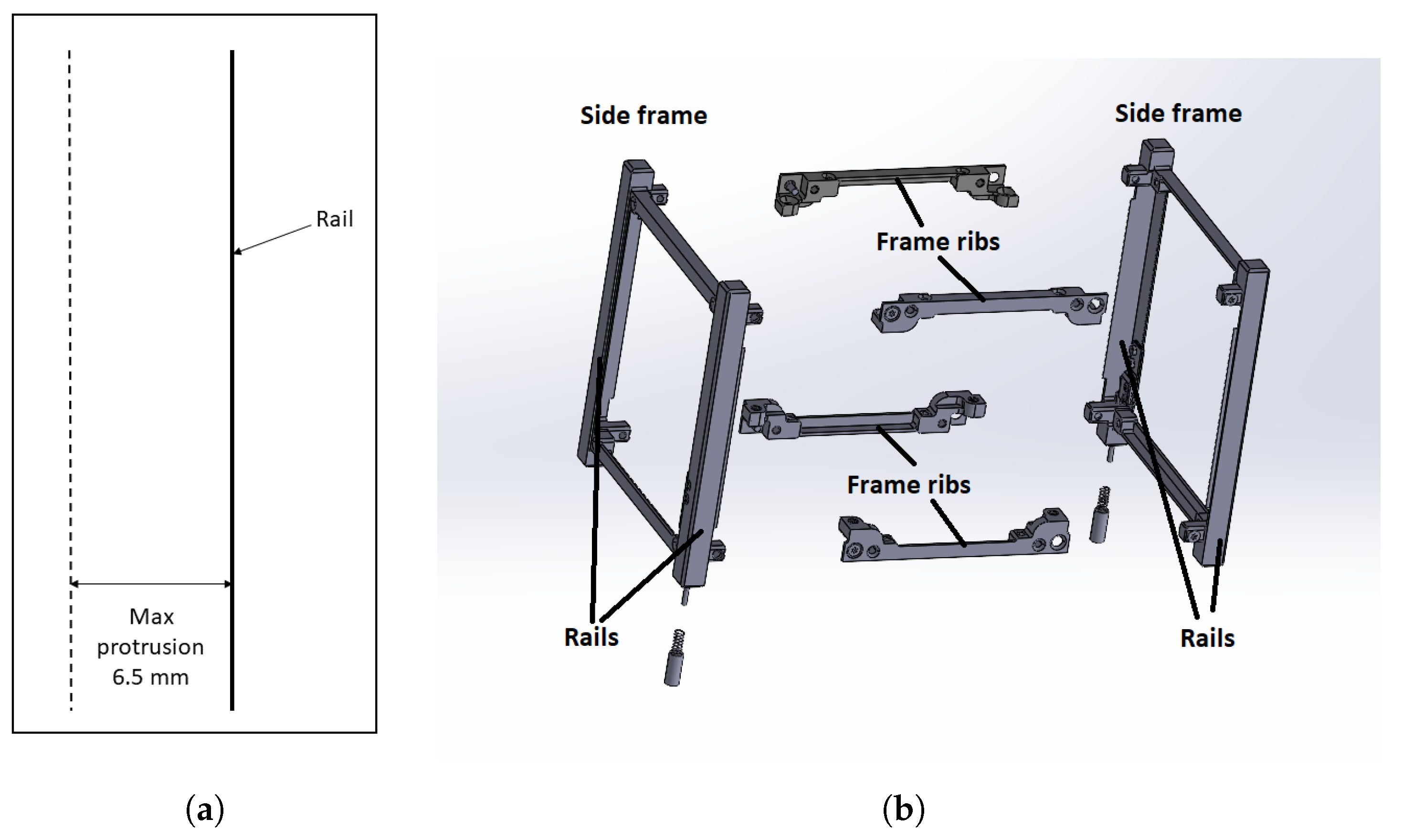
Figure 1. (a) Maximum protrusion allowed from the plane of the rails; and (b) commercial CubeSat skeleton.
Aerospace 10 01009 g001
Figure 2. (a) Sectional view of the embedded battery tile; (b) front view of the tile with hidden external components; (c) two embedded battery tiles mounted on the CubeSat commercial skeleton. The tile in the foreground is complete, while for the lateral tile, the external components were hidden to show the LiPo batteries colored in grey. Tile side length scale: 100 mm, tile thickness scale: 5 mm.
Aerospace 10 01009 g002
Figure 3. Example of the payload design space amplitude A as a function of the number of payload configurations P.
Aerospace 10 01009 g003
Figure 4. CubeSat schematization for the study case.
Aerospace 10 01009 g004
Figure 5. Complete results for the 1U, 2U, 3U, and 6U cases: (a) CubeSat volumetric increment δ C S as a function of total CubeSat volume V C S and number of tiles k; (b) specific design space amplitude A * as a function of total CubeSat volume and payload modules thickness t p a y l .
Aerospace 10 01009 g005
Figure 6. Embedded battery views: (a) tile detailed exploded view, showing its components; (b) tile exploded view with a subdivision of the tile in the outer assembly, facing space and the inner assembly, facing the inner payload bay. Tile side length scale: 100 mm, tile thickness scale: 5 mm. The component thicknesses are as follows: batteries—4.5 mm, PCBs—0.8 mm, skins—0.23 mm, and solar cells—0.17 mm.
Aerospace 10 01009 g006
Figure 7. Electrical energy capacity of the state-of-the-art CubeSats. The ARAMIS prototypes with the embedded battery tiles are indicated in blue.
Aerospace 10 01009 g007
Figure 8. CFRP skins manufacturing: (a) aluminum mold for inner and outer skins; (b) tool traces on the outer skins; (c) fiber alignment defect in the outer skins. Mold approximate dimensions: 220 × 100 × 15 mm. Skin sides length scale: 100 mm, thickness: 0.23 mm.
Aerospace 10 01009 g008
Figure 9. Embedded battery tile prototype assembly sequence: (a) bonding of the inner PCB to the inner skin with epoxy resin; (b) the soldering of the LiPo batteries terminals to the connection pads of the inner PCB; (c) application of the thermal conductive paste on the batteries; (d) gluing of the inner assembly to the outer assembly; and (e) polymerization of the siliconic adhesive with the subassemblies mounted on the commercial CubeSat frame.
Aerospace 10 01009 g009
Figure 10. Final result of the assembly procedure: (a) complete embedded battery tile prototype; (b) prototype fit check with the commercial frame; and (c) the prototype underwent mass breakdown by components.
Aerospace 10 01009 g010
Figure 11. Experimental setup for the modal analysis: (a) complete schematic of the setup; (b) piezoelectric actuator glued on aluminum panel; (c) testing frame and target; and (d) complete physical layout.
Aerospace 10 01009 g011
Figure 12. Fixing system for the outer skin (a) and for the inner PCB (b). Laservibrometer scan points are shown in red.
Aerospace 10 01009 g012
Figure 13. Design of the experiment to evaluate different actuator locations for the outer skin: (a) shapes of modes 7–9 for free–free boundary conditions; (b) possible configurations of the piezoelectric actuator; and (c) NASTRAN nodes considered for the frequency–response analysis.
Aerospace 10 01009 g013
Figure 14. Results of the frequency–response analysis for the two possible configurations for the outer skin. The plots show the magnitude of the velocity orthogonal to the plane of the skin, as a function of the excitation frequency for each node.
Aerospace 10 01009 g014
Figure 15. Modal assurance criterion (crossMAC) for the tile prototype components: (a) inner skin; (b) outer skin; (c) inner PCB; and (d) outer PCB.
Aerospace 10 01009 g015
Figure 16. Mean frequency response spectra for the tile prototype components: (a) inner skin; (b) outer skin; (c) inner PCB; and (d) outer PCB.
Aerospace 10 01009 g016
Figure 17. Structural mode visualizations for the complete tile prototype. Left: mode 7; center: mode 8; right: mode 9. Upper row: experimental modes; lower row: FEM modes.
Aerospace 10 01009 g017
Figure 18. Results for the complete tile prototype: (a) crossMAC; and (b) mean frequency response spectra.
Aerospace 10 01009 g018
Table 1. CubeSat volumetric increments δ C S for an increasing number s of tiles with δ = 4.71 % .
s δ CS
[-] [%]
14.71
29.89
315.60
421.94
529.02
636.97
Table 2. Outer skin eigenfrequencies for free boundary conditions.
ModeFrequency
[-] [Hz]
781.407
8104.99
9242.8
Table 3. Materials’ mechanical properties used in the FEM analyses allow the correlation with the experimental results.
Material E ν G ρ
( GPa ) (-) ( GPa ) ( g / cm 3 )
Aluminum62.000.30023.8502.72
FR-47.500.3002.8801.80
Copper110.000.30042.3108.93
Equivalent
battery material
0.100.3000.0382.50
E 11 = E 22 ν 12 G 12 ρ
( GPa ) (-) ( GPa ) ( g / cm 3 )
CFRP28.000.0442.0001.54
Table 4. Eigenfrequencies for tile components: comparison between experimental and numerical SOL 103 results.
ComponentModeFrequency Δ
ExperimentalSOL 103
(-)(Hz)(%)
Inner
skin
161.1364.094.9
280.5081.020.6
3160.75166.033.3
Outer
skin
158.2555.425.1
269.5072.294.0
U184.25--
3163.88166.321.5
4195.63--
Inner
PCB
1271.00298.5210.2
2428.38397.127.9
3675.00544.9223.9
4762.63754.321.1
5772.13766.830.7
Outer
PCB
1168.75219.4730.1
2292.25293.710.5
3484.13438.2410.5
4500.00535.047.0
5585.13607.283.8
Table 5. Eigenfrequencies for the complete tile prototype: comparison between experimental and numerical results.
ModeFrequency Δ
ExperimentalSOL 103
(-)(Hz)(%)
1460.78507.9410.2
2814.53748.688.8
3953.131015.806.6
41319.221080.2022.1
51439.221138.0026.5
Disclaimer/Publisher’s Note: The statements, opinions and data contained in all publications are solely those of the individual author(s) and contributor(s) and not of MDPI and/or the editor(s). MDPI and/or the editor(s) disclaim responsibility for any injury to people or property resulting from any ideas, methods, instructions or products referred to in the content.