Abstract
The bolt connection structure is widely used in the connection of aeroengine parts, and its connection quality is very important, as it can directly affect the geometric and dynamic performance of the aeroengine. Taking the bolt preload as the entry point, the research status of bolted aeroengine connections in recent years is summarized based on the bolt preload formation mechanism and control technology in this review. For the research of the preload formation mechanism, single and multiple bolts of aeroengine bolt arrays are analyzed. According to the characteristics of aeroengine bolt connections, the research of aeroengine bolt preload control technology is divided into two parts: bolt tightening technology, and bolt tightening equipment. Finally, based on the summarization of the research, the future research prospects are evaluated and discussed.
1. Introduction
As a representative of high-precision power equipment, aeroengines are among the most precise and complex engineering machinery systems in the world. The connection structure of aeroengines mainly includes the bolt connection structure, curvic coupling connection structure, rabbet connection structure, and spline joint structure, of which the bolt connection structure is the most used—especially the rabbet bolt connection structure and the precision bolt connection structure [1]. The bolt connection structure is widely used in rotor and stator parts such as compressor spools, compressor disks, turbine disks, cases, and shafts, as shown in Figure 1.
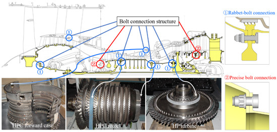
Figure 1.
Typical aeroengine bolt connection structure distribution and location diagram.
The bolt connection structure of an aeroengine is fastened by a bolt array containing many bolts (about 32~60 for rotors and 60~140 for casings). The loading of the bolt preload is the key point of fastening. In the process of aeroengine bolt connection, the bolt preload cannot be directly controlled. Generally, through a certain tightening method, the tightening equipment is used to control the tightening torque, tightening angle, and other tightening process parameters to achieve the loading of the bolt preload indirectly. This loading method provides insufficient control over the bolt preload, which will cause the bolt preload to be inconsistent for the numerous bolts in the bolt array. In addition, part of the space of the bolt connection structure in aeroengines is small, and the use of general tightening equipment to tighten bolts in this structure will cause great difficulty in manual operation, seriously affecting the implementation accuracy of the tightening process and, ultimately, affecting the tightening quality of the bolts. Moreover, the bolts need to be disassembled repeatedly during trial assembly, test runs, and maintenance [2], greatly affecting the bolts’ tightening efficiency. The working environment of aeroengines is harsh, with the characteristics of high temperature, high pressure, and high speed. When the degree of control over the bolt preload is insufficient, it will directly affect the assembly quality of the bolted connection structure, including the degree of tightness between parts [3], structural deformation [4], contact stiffness [5], and nonlinear transmission characteristics [6], further affecting the sealing performance [7], friction and wear performance [8], stator clearance [9], stator support concentricity [10], connection stiffness (tension, compression, bending, and torsion stiffness) [11], rotor imbalance [12], and dynamic response characteristics [13] of parts under cyclic loads, which ultimately causes large vibration of the whole aeroengine [14] and affects the working life of the aeroengine in the harsh environment [15].
In view of the above problems of aeroengine bolt connections, more and more scholars have carried out extensive research on bolt preload through theoretical analysis, numerical simulation, experimental research, and other means. However, due to the complexity of the bolt connection structures of aeroengines, there are many factors affecting the bolt preload. The above research has mainly been carried out on specific aspects, and there is no systematic summary of the change laws of the bolt preload of aeroengines. Many researchers still face obstacles to fully understanding how to control the bolt preload of aeroengines. In light of this, based on the summary of relevant research findings in recent years, this paper divides the bolt connection problem of aeroengines into two aspects: bolt preload formation mechanism, and control technology. The bolt preload formation mechanism is the theoretical basis of control technology, and the bolt preload control technology is the application of the formation mechanism.
The rest of this paper is organized as follows: Section 2 introduces the bolt preload formation mechanism. According to the characteristics of many bolts in the aeroengine bolt array, the preload formation mechanism of a single bolt and multiple bolts is introduced in turn from the part to the whole. Section 3 presents the bolt tightening process, including tightening process parameters and tightening methods. Section 4 describes the tightening equipment used to implement the bolt tightening process, including the tightening equipment in the open space and narrow space of the aeroengine. Finally, Section 5 presents the conclusions of this paper and the future research directions for the bolt connections of aeroengines.
2. Bolt Preload Formation Mechanism
In order to adapt to the special working environment of the aeroengine, compared with ordinary bolts and nuts, the bolts and nuts commonly used in aeroengines have the following characteristics: In terms of materials, the material is a superalloy, which can maintain good mechanical properties at higher temperatures, bear large loads and high temperatures, and has the advantages of light weight, high strength, and corrosion resistance compared with ordinary bolts and nuts. In terms of structure, the most common bolts of aeroengines are D-type bolts, which are composed of a head, polished rod, and thread. The top view of the head resembles the capital letter D, so these are called D-type bolts [16]. The nuts most commonly used in aeroengines are self-locking nuts with good anti-loosening performance [17]. The bolts and nuts most commonly used in aeroengines are shown in Figure 2.
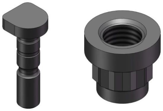
Figure 2.
The bolt and nut types most commonly used in aeroengines [16].
In spite of the above characteristics, the tightening method of aeroengine bolts and nuts is the same as that of ordinary bolts and nuts. The torque is applied to the nuts by the tightening equipment to make the nuts rotate. The thread pairs between the bolts and nuts mesh, the bolts stretch under tension, and the compression deformation of the connected parts occurs under the pressure. The tensile force of the bolt is called the bolt preload, which is equal to the pressure of the connected parts, so as to compress the connected part and achieve the tightening effect. Therefore, the summary of the formation mechanism of the aeroengine bolt preload is mainly based on the current research on the formation mechanism of the common threaded connections. In addition, the research on self-locking nuts is also discussed.
As the preload is usually applied to each bolt in a certain sequence [18], the distribution of the preload of multiple bolts in the bolt array is mainly determined by the following two aspects: first, the torque is converted into the bolt preload for a single bolt; second, the tightened bolts affect the bolt preload of the untightened bolts. Therefore, the relevant research on the formation mechanism of bolt preload is summarized, including single and multiple bolts.
2.1. Preload Formation Mechanism of a Single Bolt
According to the aviation industry standards [19,20], the relationship between the tightening torque M and the preload F of the common bolt can be expressed as follows:
where d is the nominal diameter of the thread, and K is the tightening torque coefficient of the bolt.
K is the correlation coefficient between the tightening torque and the preload when tightening the bolt, reflecting the efficiency of converting the tightening torque into an effective preload, and the magnitude and variation law of this coefficient provide important guidance for the design, manufacture, and installation of the bolt connection. Combined with the mechanical model of the bolt tightening process described by Motosh [21] and Gong et al. [22], the theoretical equation of the tightening moment coefficient of a common triangular thread bolt can be derived as follows:
where P is the thread pitch, is the friction coefficient of the threaded substrate, is the friction coefficient of the nut support surface, is the effective friction radius of the threaded substrate, is the effective friction radius of the nut support surface, and is the thread profile’s half-angle.
The main geometric parameters of the thread and the name of each contact surface are shown in Figure 3. In practical applications, the effective friction radius of the threaded sub is generally expressed as an approximation of the average radius of the thread. For a triangular thread, it is half of the thread’s median . This approximation was proven to be sufficiently accurate by Ganeshmurthy et al. [23] and Nassar et al. [24], who compared the calculation of the effective contact radius of the threaded sub with the average radius of the thread and found that the difference between the two was generally less than 1%, regardless of the assumed pressure distribution. Since the tightening torque–preload transformation relationship mainly depends on the accuracy of the friction coefficient and the effective contact radius, the study of the mechanism of preload formation in single bolts has mainly focused on the study of these two parameters.
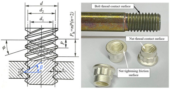
Figure 3.
Main geometric parameters of the thread and contact surface position.
In the study of friction coefficients, Ganeshmurthy et al. [25] investigated the effects of different tightening speed combinations (1~150 rpm) on the tightening torque–preload relationship and the friction coefficient of the threaded sub and support surface, finding that a reasonable choice of tightening speed was essential for the formation of the preload. Eccles et al. [26] investigated the effects of repeated tightening on the friction coefficient by repeatedly tightening and loosening the nuts with galvanized surface treatment. Graboń et al. [27] studied the effects of heating conditions on the tightening process of bolted joints and determined the effects of thermochemical conditions on the friction coefficient by examining the structural crystal phase of the bolts, the tightness of the joints, and the surface hardness. Pi [28], Meng [29], Liu [30], and Croccolo et al. [31] carried out an experimental study of the effect of the friction coefficient on the loading torque–preload relationship, and a quantitative analysis of the friction coefficient effect was performed.
In the study of friction radius, Zou et al. [32] proposed an integration method of friction radius based on two forms of contact pressure distribution—exponential and sinusoidal functions—and found that the method had higher accuracy when the surface roughness was small by experimental comparison. Nassar et al. [33,34,35,36] proposed a friction radius integration method based on two forms of uniform and linear contact pressure distribution, considering the effects of tightening speed, three-dimensional thread geometry, and dynamic–static friction factors, by means of a tightening test system that can measure the decomposition torque; they concluded that the tightening speed was an important factor affecting the uncertainty of the thread friction radius, as shown in Figure 4. Furthermore, orthogonal tests were conducted on steel and aluminum connectors to study the variation in the tightening torque–preload transformation relationship under different scales of surface roughness, different contact surface materials, and different thread parameters. The results showed that the contact stress magnitude and the yield strength of the material had a greater influence on the friction factor, and that repeated tightening and unscrewing increased the surface roughness.

Figure 4.
The tightening test system used by Nassar to measure decomposition torque [36].
In addition, Chen [37] and Liu [38] from Dalian University of Technology introduced manufacturing errors into the bolt preload formation process in the tightening stage, as shown in Figure 5, and investigated the influence of pitch deviation and non-parallel contact surface on the tightening torque–preload transformation relationship through experiments and simulations. They found that each manufacturing deviation would directly or indirectly affect the contact stress distribution of the threaded sub and nut support surface through coupling interaction, causing variations in the effective friction radius and friction torque, thereby affecting the tightening torque–preload transformation relationship.
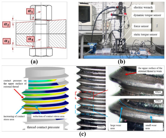
Figure 5.
Schematic diagram of the bolt contact stress distribution after introducing manufacturing errors [37,38]: (a) Cumulative nut support surface non-parallelism deviation. (b) Tightening test system. (c) CCD image of thread surface wear after tightening.
From the abovementioned research status, it is clear that the formation of the preload of a single bolt mainly depends on the transformation relationship from the tightening torque to the preload, in which the friction coefficient and the effective friction radius of the nut support surface, along with the thread surface, play an important role. The coefficient of friction is influenced by the material type, surface roughness, surface coating, lubrication conditions, number of repetitions, and tightening speed, while the effective friction radius is influenced by the non-parallelism between the nut and the connected part, the manufacturing error of the bolt, the number of repetitions, and the tightening speed. However, there is less research on the interaction mechanisms of the above factors (for example, between the friction coefficient and effective friction radius, or between the process parameters and structural parameters). With the goal of effectively reducing and controlling the amount of preload fluctuation caused by the friction coefficient and the effective friction radius during the tightening process of aeroengine bolts, in-depth research on the interaction mechanisms between the influencing factors is the focus of the study of the formation mechanism of single bolts.
2.2. Preload Formation Mechanism of Multiple Bolts
When a group of bolts are tightened in the same tightening process, each bolt can theoretically form the definite preload. However, in the single-axis tightening process, the preload of the first tightened bolt will change several times when the later bolts are tightened. This phenomenon is called bolt elastic interaction [39], as shown in Figure 6, and the intuitive reason is that the connected parts are deformed by the pressure of the tightening process.

Figure 6.
Schematic diagram of bolt elastic interaction.
In 1992, Bibel et al. [40] proposed the elastic interaction coefficient matrix and established the mapping relationship between the relative positions of the bolts and the deformation distribution of the connected parts. They concluded that the tightening of bolts at neighboring positions decreased the bolt elongation, while the tightening of bolts at diagonal positions increased the bolt elongation, which caused the elastic interaction to gradually decrease with the increase in the preload. Takaki et al. [41] used simulations to study the change rule of bolt preload with time during flange connection tightening. The elastic interaction coefficient matrix obtained by simulation was used to design the initial preload, which reduced the fluctuation of the multi-bolt preload by 15%. Alkelani [42] and Nassar et al. [43,44,45] proposed a mathematical model of elastic interaction affected by four factors: gasket material, gasket thickness, bolt spacing, and tightening sequence. The model showed that the elastic interaction increased with increasing shim thickness. The tightening sequence significantly affected the preload and uniformity of the final bolt set. The average loss of preload increased significantly with decreasing bolt spacing, and the percentage loss of preload was independent of the preload; the effect of preload on the elastic interaction was not significant. As shown in Figure 7, Abasolo et al. [46] proposed a more general parametric theoretical model based on the elastic interaction coefficient method, which was used to calculate the axial load that should be applied to each bolt and could achieve a final residual preload that was closer to the target preload. Wang et al. [47] proposed an analytical model of multi-bolt elastic interaction based on the simplified model of “spring-node” and the interaction stiffness, and further elaborated on the effect of bolt stress relaxation on the distribution of preload. Grzejda R. et al. put forward a calculation model of dissymmetric nonlinear multi-bolt connections as a system that could predict bolt preload variations and provide the analysis of how the tightening sequence affected the bolt preload [48].

Figure 7.
Parametric model of elastic interaction developed by Abasolo [46]: (a) physical drawing of the flange bolt array; (b) flange feature dimensions; (c) elastic interaction equivalent model.
As shown in Figure 8, Ye [49] researched the rabbet bolt connection structure based on tests and simulations, and they found that under ideal base conditions (i.e., no manufacturing deviation on the contact surface), when the bolt spacing was small, the later-tightened bolt decreased the preload of the first tightened bolt, and the elastic interaction between adjacent bolts gradually decreased as the bolt spacing increased. Under actual contact conditions, as the contact surface bulge increased, the later-tightened bolt increased the preload of the first tightened bolt, but the bolt spacing had little effect on the elastic interaction relationship.

Figure 8.
Comparison of stress clouds under ideal and actual contact conditions [49].
From the above research status, it can be seen that the formation of the preload of a group of bolts under the moment method is mainly dependent on the elastic deformation of the connected parts, which is vulnerable to the tightening sequence and the actual contact state of the mating surface. In the design of the bolted structure, the shim material, shim thickness, bolt spacing, and the design size of the preload can all affect the elastic interaction and need to be chosen reasonably in the design to reduce the influence of elastic interaction.
3. Bolt Tightening Process
For the aeroengine bolts, as the connection form is a bolt array composed of multiple bolts, the requirements for preload are not only to meet the design standard of a single preload, but also to meet the required consistency of multiple preloads. The control technology of bolt preload is an important research direction for aeroengine bolt connections. Based on the formation mechanism of bolt preload described in Section 1, it can be seen that the formation process of bolt preload is directly affected by the tightening process, and a reasonable tightening process can improve the consistency of the bolt preload. Due to the limitations of tightening equipment, sometimes the tightening process cannot be accurately implemented, which has an impact on the consistency of the bolt preload. Therefore, the bolt preload control technology can be understood as the design of a reasonable tightening process and the implementation of appropriate tightening equipment to ultimately control the size and consistency of the bolt preload. Based on these two aspects, the research in recent years is summarized below.
3.1. Bolt Tightening Process Parameters
Bolt tightening process parameters include the tightening sequence, tightening speed, tightening step, tightening times, lubrication conditions, and other aspects [50]. Among them, there are many kinds of bolt tightening sequences, including sequential tightening, cross-tightening, triangular tightening, symmetrical tightening, etc. How to choose an optimal sequence to complete the tightening of all bolts has been a key concern. The tightening steps refer to the number of steps used to tighten to the target torque. For example, if the bolt is tightened to the target torque in two steps, the tightening method is called “2 steps”. The torque of each step is called the step size. The tightening times refer to the number of instances of repeatedly tightening the bolts. The lubrication conditions refer to the conditions among the bolts, nuts, and connected parts. For these process parameters, many scholars have carried out research through theoretical analysis, simulation calculations, and experimental research, including research on individual process parameters and research on the coupling influence laws of several of them.
Hou [51] established a six-bolt finite element model of the flange bolt structure and studied the effects of four tightening sequences—sequential, cross-tightening, triangular tightening, and symmetric tightening—on the bolt connection quality (i.e., preload uniformity, form center, flange cylindricity, flange clearance). As shown in Figure 9, the standard deviation of the preload was the smallest under diagonal tightening; the flange cylindricity was the best under sequential tightening, but the form’s center position changed; the cylindricity and the position of the flange center were moderate under cross-tightening, and the flange gap mainly appeared in the inner ring of the flange, so the cross-tightening sequence was optimal. In addition, Chen [52] and Hao et al. [53] studied the optimization of the bolt tightening sequence by establishing finite element models for simulation analysis, in which Chen Shuang [54] established a 16-bolt finite element model of the rabbet bolt structure and studied the effects of the process combination of tightening sequence and tightening step on the bolt connection quality (i.e., preload uniformity, stop deformation, flange centering) to determine the optimal tightening sequence. It was found that the “2 steps” method was better than the “1 step” method, and the cross method B was better than the cross method A, as reflected in the smaller preload fluctuation and smaller deformation offset. Figure 10 shows the two methods.
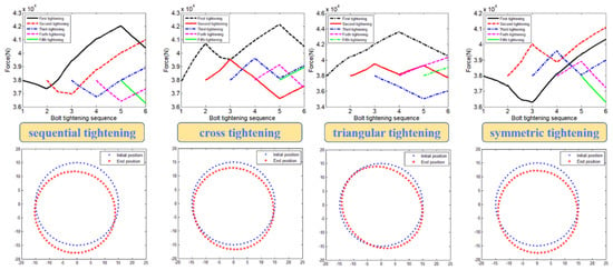
Figure 9.
Comparison of the effects of four tightening sequences on the change law of bolt preload and flange deformation [51].

Figure 10.
Finite element model of 16 bolts and the sequence diagrams of cross-tightening methods A and B [54].
The “Guidelines for Pressure Boundary Bolted Flange Joint Assembly” issued by ASME [55] in 2019 recommended a series of tightening sequence solutions for flange-bolted structures, including single-axis, dual-axis, and four-axis general tightening methods, of which the most representative method was the criss-cross tightening method under a single tightening axis (all bolts are tightened in three steps according to the criss-cross sequence, and the tightening torque is gradually increased to 100% of the target torque), which resulted in a more uniform preload, but the process was complicated and costly. Tsuji [56] proposed a clockwise tightening method (i.e., tighten all bolts with a target torque of no more than 20%, and then tighten all bolts with a target torque of 100% in the clockwise direction), and it was considered that the preload obtained was also more uniform in size and the process was simple. However, Fukuoka and Kumakura et al. [57,58] found that although the clockwise tightening method avoided the complexity of the number of tightening steps and the tightening process, it was more likely to cause uneven gaps in the mounting edges, tilt the mounting edges, increase the concentricity of the assembly, and reduce the connection quality of the connected parts; as shown in Figure 11, they optimized the tightening method by combining the criss-cross and clockwise tightening methods. The improved clockwise tightening method achieved approximately the same connection quality as the cross-tightening method and shortened the tightening process.
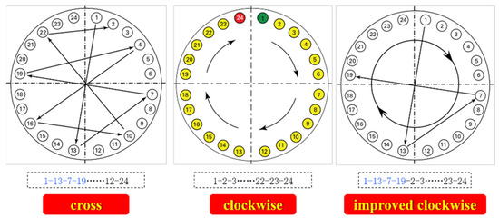
Figure 11.
Brief diagram of the three tightening methods.
In the separate study of other process parameters, Zou et al. [59], Lian [60], and Wang [61] studied the effect law of lubrication conditions on the preload magnitude through experiments and found that adequate lubrication would reduce the value and fluctuation of the preload magnitude and friction factor. Wang et al. [62] established a finite element model of bolted connections with real rough contact surfaces and proposed that bolts tightened at a fast and then slow speed were better than those tightened at a constant speed or at a slow and then fast speed. Ma et al. [63] established a six-bolt finite element model of a flange bolt structure and studied the distribution law of residual preload and contact surface stress according to the tightening step length of the bolts. Zhu et al. [64] established an eight-bolt finite element model of pipe flange bolts and reduced the influence of elastic interaction by optimizing the initial loading force of the bolts. Combined with the tightening process of three loading times, the fluctuation of the final residual preload was reduced to within 10%, as shown in Figure 12, which shows the preload monitoring curve of the eight bolts throughout the whole three-step tightening test.
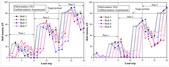
Figure 12.
The change curve of bolt preload during the three-step tightening test [64].
Huang [65] analyzed the influence law of the number of tightening steps, tightening step length, and tightening sequence on the fluctuation of the preload by combining the principles of elastic positive and negative interactions, and proposed a two-step loading method for the flange bolt structure without rabbet: a first step using the crossover method to tighten to 80% of the target preload, and a second step using the sequential tightening method to tighten to the target preload. Duffey [66], Vincenzo [67], Hu [68], and Li G et al. [69] determined the main factors that affected the bolt preload by establishing a three-dimensional bolt tightening model and optimized the process parameters for applying the bolt preload. Li et al. [70,71] studied the effects of the tightening method, the number of tightening steps, and the tightening speed on the magnitude and stability of the preload based on the TC4 titanium alloy single-bolt connection process test, explored the short-term decay law of the bolt preload, and found that the use of the torque angle method, the use of three-step tightening, and the increase in rotational speed could smooth the fluctuation of the preload and, thus, improve the control of the preload. As shown in Figure 13, Zhao et al. [72,73] investigated the effects of tightening time, lubrication method, and bolt and nut quality on the uniformity of the bolt preload using the torque method for the deflated nut tightening control of the aeroengine’s rotor flange bolt connection structure, and proposed a correction model for the tightening torque–preload relationship including the self-locking torque, finding that repeated tightening would affect the surface. It was found that the surface roughness would be reduced by repeated tightening, while sufficient lubrication could reduce the fluctuation of the preload.
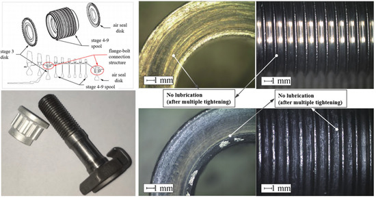
Figure 13.
Wear of bolt threads under different lubrication conditions [72].
The application objects of the above research mainly focused on flange bolt connection arrays with circular distribution, and there has been less research on rabbet bolt connection structures in aeroengines. Moreover, the main research method is simulation, which brings a problem of the loading of the bolt preload. It is the direct loading of axial force on the bolt—instead of applying torque to the nut and then elongating the bolt through the threaded sub—that ignores the formation process of the single-bolt preload and the influence of many factors, such as tightening speed and lubrication conditions. Therefore, the reliability of the optimized tightening process obtained by this method is low.
3.2. Bolt Tightening Method
The bolt tightening method is the loading method of the bolt preload. The different loading methods directly affect the magnitude of the bolt preload. According to the control degree of the preload during loading, the bolt tightening methods can be divided into three categories: open-loop control, semi-open-loop control, and closed-loop control. Among them, the torque method and torque angle method are common in open-loop control. The common methods in semi-closed-loop control include the pre-stretching control method and the yield point method, while the common methods in closed-loop control include the elongation detection method and the bolt loading method.
In the bolt tightening process, there is a certain loss when the tightening torque is transformed into preload, due to the influence of geometric size error between parts, shape error, surface roughness, and the physical properties of the workpiece [74]. The preload error obtained by the torque method is ±5%–±35%, and the worst will reach ±50%. The preload error of the torque method is the largest among all bolt tightening methods [75,76]. The schematic diagram of the preload error generated when tightening bolts via the torque method is shown in Figure 14. Combining the Taylor series expansion method and the Monte Carlo method, Toth [77] studied the control of bolt preload in the elastic and plastic zones by using the torque angle method of tightening, as shown in Figure 15. As this method can indirectly control the bolt elongation, the control accuracy of the bolt preload can be improved, and the preload error range can be controlled to ±15% [78]. However, the method needs to determine the initial torque and provide an approximate complete contact between the bolt and the nut. Based on the parameters of the tightening state, Sun [79] proposed an improved torque angle method to attenuate the friction uncertainty factor. Fukuoka et al. [80] proposed an elastic area angle control method for bolt preload control, established the relationship equation between axial load and rotation angle, and formed a set of feasible tightening process specifications.
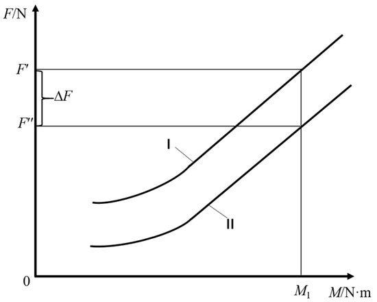
Figure 14.
Torque method for tightening bolts [79].
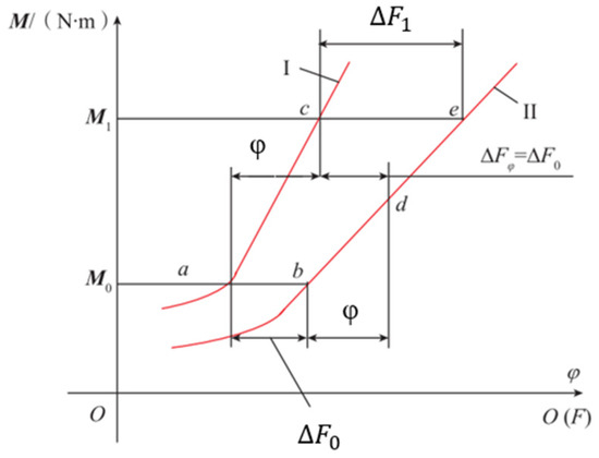
Figure 15.
Torque corner method of tightening bolts [79].
In order to further improve the bolt utilization, researchers have also proposed the yield point method, which controls the bolt tightening process by using an algorithm to monitor the torque variation rate during the tightening process [81]. When the judged tightening torque reaches the fitting torque, the torque variation rate is monitored and the maximum value of the torque variation rate is stored until the torque variation rate drops to 1/3–1/2 of the maximum value; then, the yield point is determined, and the yield point tightening of the preload is completed. Hashimura et al. [82] proposed the elongation method to control the preload of the bolt, which requires the measurement and control of the elongation of the bolt, and many scholars have studied this method. Nassar et al. [83] used the ultrasonic ranging technique to control the elongation of the bolt. The measurement of bolt elongation was achieved by using the multi-sensor data fusion technique by Tang [84]. Mizutani et al. [85] used the acoustic emission technique to measure the bolt plastic deformation elongation and control the preload in the plastic zone of the bolt. Huang [86] used an optical force sensor to measure the preload during bolt tightening by measuring the washer strain. Fukuoka [87] and others investigated the correspondence between the bolt tensile stress and the preload using three methods: numerical analysis, finite element analysis, and experiments. Grzejda R. et al. [88] proposed a method of tension control by monitoring the values of the forces in the bolts using a calibrated measuring system based on resistance strain gauges, which could achieve a more even distribution of the bolt preload. In summary, the yield point method and the bolt elongation method can control the bolt preload error to ±5%, but the control cost is high and the application is limited. According to the above research status, the principles, advantages, and disadvantages of these methods are summarized in Table 1.

Table 1.
Summary of bolt tightening methods.
It can be seen from the above summary of common bolt tightening methods that the selection of bolt tightening methods should not only involve the accurate control of the preload, but also convenience of operation and cost. For the bolt connection structure of an aeroengine, the demand for the latter is greater. Therefore, although the control accuracy of the torque method is poor, it is widely used in aeroengine bolt tightening due to its advantages of simple operation and low cost. In addition, the torque angle method is also used to improve the accuracy of preload for some bolted parts that require high control accuracy (such as the low-pressure turbine disk shaft assembly).
4. Bolt Tightening Equipment
As shown in Figure 16, the assembly and connection of the stator system generally adopt the outward-flip flange bolt array, so the tightening equipment generally has an open tightening space, and the requirements for the tightening equipment are not high. In contrast, the assembly and connection of the rotor system generally adopt an inward-flip mounting edge flange bolt array. Due to the complex and compact structure of the rotor parts, it is easy to form a narrow internal cavity that is not directly visible. The requirements for the tightening equipment are high: firstly, it must not touch the aeroengine parts during the process of reaching the internal tightening position from the outside; secondly, the available operating space is extremely narrow and compact; and finally, the tightening process must be performed accurately. Therefore, the tightening equipment must be sufficiently automated and intelligent for such demanding tightening conditions. Based on the above, an overview of tightening equipment for aeroengines is presented below with respect to both open space and narrow space.
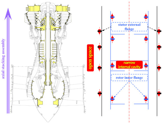
Figure 16.
Schematic diagram of an aeroengine stator–rotor substructure system’s tightening space.
4.1. Open-Space Tightening Equipment
For bolt arrays in open space, due to the good visual conditions and spacious operation space, the tightening work is usually completed by manual use of tightening equipment or by automated tightening equipment. The following are the main kinds of manual tightening equipment: ordinary wrenches, bow wrenches, constant-torque wrenches, and electric wrenches.
Ordinary wrenches, with their flexible design and simple structure, can fully meet the requirements of the axial and radial dimensions. However, they cannot achieve continuous tightening, and their efficiency is extremely low—not to mention their inability to accurately control the tightening torque. Therefore, ordinary wrenches are generally used in non-critical connection parts where the tightening torque is not required. The bow wrench is an improvement on the ordinary wrench, and it is generally oriented to the bolt connection parts with partially open vision but a compact radial dimension. It has the same problem as the ordinary wrench, in that it cannot achieve continuous tightening and accurately control the tightening torque. The physical diagrams of these two devices are shown in Figure 17.
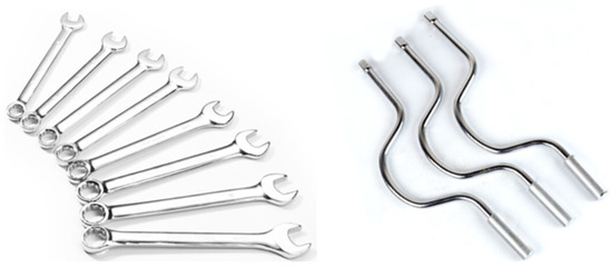
Figure 17.
Ordinary wrenches and bow wrenches.
The constant-torque wrench can apply a specific torque value to the bolt and adjust the tightening torque. Some constant-torque ratchet wrenches can achieve continuous tightening, and this function is related to the structure of the tightening head. The tightening torque control accuracy of the constant-torque wrenches varies depending on the brand, and the tightening torque is applied manually, so the actual torque value applied to the bolt fluctuates greatly. Figure 18 shows a constant-torque wrench used in the assembly of an aeroengine [89,90].
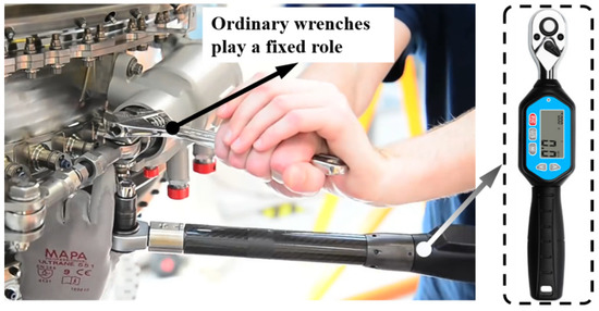
Figure 18.
Schematic diagram of a constant-torque wrench [89,90].
Electric wrenches apply accurate tightening torque to the bolts through the self-rotation of the tightening sleeve, and the user only needs to play the role of holding the electric wrench. The most widely used brands, such as Atlas Copco electric wrenches, have a tightening torque accuracy of ±3% or less. The rotation angle is monitored in real time, and the tightening speed is smooth and adjustable, so the electric wrenches can perform various tightening processes accurately and stably, and the quality consistency of their bolt connections is better, as shown in Figure 19.
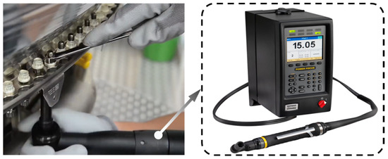
Figure 19.
Schematic diagram of an electric wrench.
Take the assembly of a GE90-115B aeroengine as an example to demonstrate the automation equipment used in open space. Due to the large mass and moment of inertia of the low-pressure turbine rotor, the connection rigidity and the stability of the bolt connection array are required to be high. Therefore, for the bolt connection array between the low-pressure turbine shaft and the low-pressure turbine rotor assembly, the automatic tightening equipment [91] is used to complete its tightening work, as shown in Figure 20. This automated tightening equipment can maintain the torque accuracy range of a DC torque wrench within ±7 N·m and the angle of rotation within ±3° by means of a torque/angle calibrator and controller; however, its tightening torque control ability is poor.
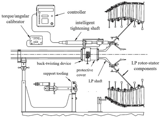
Figure 20.
Automated tightening equipment used in a GE90-115B aeroengine [91].
It is clear from the abovementioned status that the tightening equipment for open spaces is mainly based on the manual use of general wrenches. The tightening torque control capability varies depending on the tightening equipment and can be selected reasonably according to the need for tightening torque accuracy and the structural characteristics of the bolts to be tightened. In general, a bolt connection array in open space does not require high-performance methods such as automation and visualization of tightening equipment.
4.2. Narrow-Space Tightening Equipment
For bolt connection arrays in narrow space, the tightening work is usually performed using special tightening equipment in this area, because it is not directly visible to the human eye. According to the degree of automation, the tightening equipment is mainly divided into manual tightening equipment and automatic tightening equipment. In addition, the degree of visualization of the tightening process (bolt tightening image visualization, real-time visualization of tightening parameters) is also considered.
For the manual tightening equipment, the entire bolt tightening process is performed manually using the equipment, and the human work is the input of the tightening torque transmission chain, which can tighten the bolt array in the narrow operating space. However, the tightening torque control capability is poor, and the determination of the position of the bolts to be tightened mainly depends on the correspondence between the internal and external bolts (there is a certain phase relationship between the bolt array in the narrow space and the bolt array in the external open space, which can be used as a positioning reference from the outside), while the visualization degree is generally low, and the visualization function is mainly based on the image monitoring of bolt tightening. Italian Marposs [92] and China Aerospace Commercial Aero-engine Company [93,94] have developed corresponding equipment for the tightening of engine rotor bolts. Figure 21 shows the Marposs manual tightening equipment used for the rotor disk cavity of the high-pressure compressor.
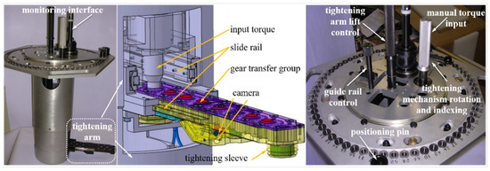
Figure 21.
Marposs visual manual tightening equipment [92].
Automatic tightening equipment means that after the equipment is manually installed to the engine, all of the tightening work is carried out by the equipment independently, and the electric wrench—as the input of the tightening torque transmission chain—can automatically ensure the stable output of the bolt tightening torque and rely on the bolt positioning module to determine the position of the bolt to be tightened. Its visualization degree is generally higher, and the visualization function is more suitable. Furthermore, it generally has the functions of the bolt tightening image. However, it is unable to ensure nut recognition, which needs to be completed by manual work to recognize all nuts in advance, meaning that the automatic tightening equipment only completes the work of limiting the force of the nuts. At present, the V2500 aeroengine [95] and LEAP-1B [96] aeroengine in the United States use this equipment in the assembly process, as shown in Figure 22 and Figure 23, respectively.
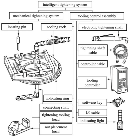
Figure 22.
Semi-automatic tightening equipment used in the V2500 aeroengine in the United States [95].
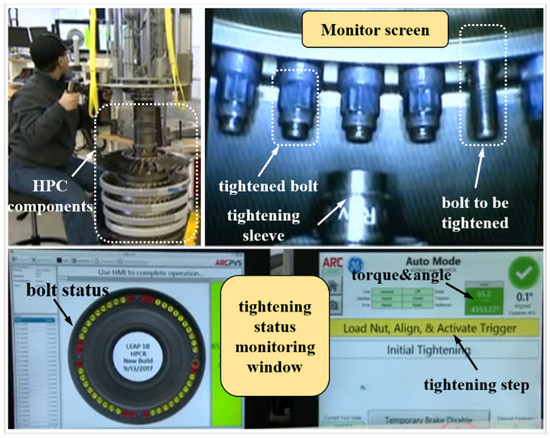
Figure 23.
Semi-automated tightening equipment used for the rotor of the high-pressure compressor of the US LEAP-1B aeroengine [96].
Dalian University of Technology has developed automatic tightening equipment for high-pressure rotor sealing disks of aeroengines [97,98,99,100,101], and AVIC Commercial Aero Engine Company has also developed automatic tightening equipment for rotor cavities and high-pressure rotor sealing disks of aeroengines [102,103]. In addition, Shenyang University of Aeronautics and Astronautics [104] has developed automated tightening equipment for high-pressure compressor sealing disks. Among them, the automated tightening equipment of Dalian University of Technology and AVIC Commercial Aero Engine Company has not seen any physical application, while the automated tightening equipment of Shenyang University of Aeronautics and Astronautics has been used by the aeroengine company.
Through the above analysis of the current situation, the tightening equipment for narrow spaces is mainly special tightening equipment, supplemented by manual tightening equipment, and the overall tightening torque control ability is higher except for that of the manual tightening equipment, effectively improving the uniformity of the preload of the bolt connection array and monitoring the bolt tightening image and tightening parameters.
5. Conclusions
The control of the preload consistency of the aeroengine bolt array has always been a difficult problem in the aeroengine assembly process. For this reason, this paper summarizes and analyzes the current status of research on the “bolt preload formation mechanism” and “bolt preload control technology”. The formation of the bolt preload includes two aspects: single bolts, and multiple bolts. Due to the existence of elastic interaction, the two will have coupling effects. The control of the bolt preload includes the bolt tightening process and bolt tightening equipment; the former guides the latter to implement bolt tightening, and the latter accurately implements the former. The relationship between the tightening mechanism and control technology is summarized in Figure 24. Among them, the formation mechanism of the bolt preload is the basis of the bolt preload control. The research of the formation of the bolt preload can provide theoretical guidance for the optimization of the bolt tightening process.
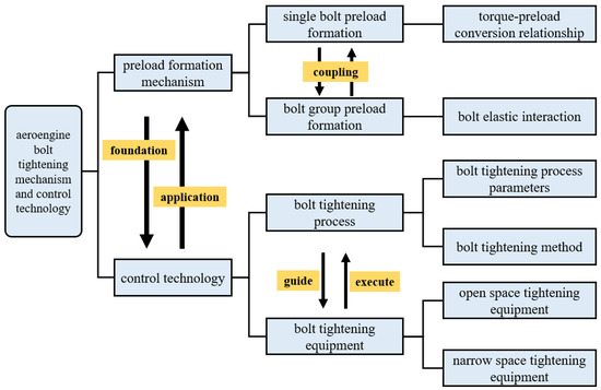
Figure 24.
Diagram of the relationship between the bolt tightening mechanism and the control technology.
By summarizing the research on the formation mechanism and control technology of the bolt preload of aeroengine bolt connection structures, we can draw the follow conclusions:
(1) In terms of the formation mechanism of the bolt preload, for the study of the formation mechanism of single-bolt preload, the torque–preload relationship equation proposed by Motosh is the most widely used. This model clarifies the linear relationship between the change in the bolt preload and the final residual bolt preload. The friction coefficient and friction radius in the tightening process of a single bolt under the torque method are two main factors affecting the preload. Many scholars have studied the formation rules of these two factors on the preload of a single bolt in terms of the tightening process (including tightening speed, tightening times, etc.), material properties, contact surface conditions (roughness, lubrication conditions, etc.), and geometric deviation. For the study of multi-bolt preload, the elastic interaction coefficient method is the most widely used model. On this basis, many scholars have proposed some improved models. Based on the theoretical model, many scholars have studied the factors that affect the elastic interaction. Through finite element simulation and experimental research, they have determined the influence laws of many factors on the elastic interaction.
(2) In terms of the bolt preload control technology, for research on the bolt tightening process, the torque method and single-shaft tightening method are generally used for bolt tightening at present. Although semi-open-loop control methods such as the yield point method and bolt pre-elongation method, closed-loop control methods such as the elongation detection method and loading method, and multi-axis tightening methods can all greatly improve the control accuracy of the bolt preload, these methods are not applicable to the tightening of aeroengine bolts, due to operational difficulties and technical costs. For research on bolt tightening equipment, scholars have developed corresponding tightening equipment for bolt connection structures in open and narrow environments to implement the bolt tightening process accurately. The bolt connection array in open space has low requirements for the automation and visualization of the tightening equipment, mainly using general wrenches manually, while the bolt connection array in narrow space requires highly automated and visual tightening equipment and mainly uses special tightening equipment.
Based on the above summary of the research, it can be seen that at present, in terms of the formation mechanism and control technology of the bolt preload of aeroengines, the following problems remain to be solved in follow-up studies:
(1) For the research on the formation mechanism of the bolt preload, most of the simulation models and test pieces established in the current research do not fully consider the characteristics of typical bolt connection structures in aeroengines, and the research results will be different from the actual formation mechanism of aeroengine bolt preload. Moreover, the formation mechanism of single-bolt preload is not combined with the formation mechanism of multi-bolt preload, resulting in a certain deviation compared with the actual tightening process. Based on these two issues, further research should be carried out.
(2) For the control technology of aeroengines, there is no breakthrough in the traditional tightening process and equipment at present. In the future, with the development of artificial intelligence, intelligent detection, and other technologies, the research direction of bolt connection control technology for aeroengines could be developed towards the precise control of bolt preload, driven by digital twins. Based on the information in the process of real-time detection of bolt connections, a two-way mapping model combining the virtual and the real can be constructed, and the changes in the bolt preload and product connection performance can be simulated and analyzed synchronously, so as to carry out real-time prediction of assembly quality. On this basis, the bolt fastening process can be optimized and, finally, the bolt connection quality can be improved, achieving the intelligent assembly of aeroengine bolt connections.
Author Contributions
Conceptualization, Z.L. and X.L.; resources, Y.H.; writing—original draft preparation, Z.L., Z.Z. and P.Z.; writing—review and editing, Z.L., P.Z., Z.Z. and M.Z.; supervision, X.L.; project administration, P.Z.; funding acquisition, G.Z. All authors have read and agreed to the published version of the manuscript.
Funding
This research was funded by the Major National Science and Technology Projects (2017-VII-0010-0104).
Data Availability Statement
There were no new data were created.
Acknowledgments
The authors gratefully acknowledge financial support from the Major National Science and Technology Projects (2017-VII-0010-0104).
Conflicts of Interest
The authors declare no conflict of interest.
References
- Liu, Y.; Liang, C.; Shi, L. General Design of Aviation Gas Turbine; Science Press: Beijing, China, 2021. [Google Scholar]
- Yan, Q. Research on Assembly Tightness Detection Method for Aeroengine Bolt-Jointed Rotor; Chang’an University: Xi’an, China, 2019. [Google Scholar]
- Zhao, G.; Wang, Y.; Zhao, X.; Li, S.; Teng, G. Modeling and application test of contact stiffness of bolt connection structure of disk and drum. J. Aeronaut. Dyn. 2022, 37, 76–86. [Google Scholar]
- Jiao, J.; Mo, R.; Xu, G.; Fu, X.; Sun, H.; Chang, Z. Influence of position error of bolt hole on assembly mechanical characteristic of short precision bolted connection structure. J. Aeronaut. Dyn. 2021, 36, 935–947. [Google Scholar]
- Li, X.; Chen, G.; Yu, P.; Yang, M. Nonlinear stiffness mechanism analysis and numerical simulation of rabbet-bolted connection structure. J. Aeronaut. Dyn. 2021, 36, 358–368. [Google Scholar]
- Wang, K.; Yan, M.; Sun, Z.; Su, D.; Hui, A.; Liu, H. Influence factors of nonlinear stiffness of bolted flange connection structure under different loads. J. Aeronaut. Dyn. 2021, 36, 2503–2514. [Google Scholar]
- Ai, Y.; Lai, C.; Han, Y.; Sun, D.; Wu, L. Experiment on sealing characteristics of bolts flanged connections for aero-engines. J. Aeronaut. Dyn. 2018, 33, 2315–2323. [Google Scholar]
- Yu, P.; Zhao, Z.; Hou, L.; Chen, G. Analysis on analytical modelling and damping characteristics of bolted joint structure with spigot. J. Aeronaut. Dyn. 2021, 36, 2490–2502. [Google Scholar]
- Deng, W.; Mo, R.; Chen, K.; Feng, X.; Xia, H.; Sun, H.; Chang, Z. Prediction of rotor blade tip assembly clearance based on measured data for aero-engine. J. Aeronaut. Dyn. 2022, 37, 1273–1283. [Google Scholar]
- Bai, S.; Zhai, X.; AI, Y.; Ma, W. The influence of Bolted Connection on the Coaxial Tolerance and Dynamic Analysis in Aero-Engine Casing. J. Aeronaut. Dyn. 2010, 6, 35–37. [Google Scholar]
- Hong, J.; Xu, X.; Su, Z.; Ma, Y. Joint stiffness loss and vibration characteristics of high-speed rotor. J. Beihang Univ. 2019, 45, 18–25. [Google Scholar]
- Fan, Z. Study on the Influence of Bolt Preload on the Non-Continuous Rotor Dynamics of Aeroengine; Harbin Institute of Technology: Harbin, China, 2020. [Google Scholar]
- Sun, W.; Li, T.; Yang, D.; Sun, Q.; Huo, J. Dynamic investigation of aeroengine high pressure rotor system considering assembly characteristics of bolted joints. Eng. Fail. Anal. 2020, 112, 104510. [Google Scholar] [CrossRef]
- Liu, Y.; Wang, D.; Hong, J.; Wu, F.; Jiang, G.; Huang, H. Analysis of Whole Aeroengine Vibration Control Technology. Aircr. Engine 2013, 39, 1–8+13. [Google Scholar]
- Sun, S.; Li, Y. Research on the Influence of Manufacturing Error of Aeroengine Rotor Installation Edge on Assembly Performance. Mod. Manuf. Technol. Equip. 2020, 56, 126–131. [Google Scholar]
- Zhang, B. Study on Loosening Regular Pattern of Bolt Connection of Low Pressure Turbine Shaft and Disc; Dalian University of Technology: Dalian, China, 2019. [Google Scholar]
- Zhang, X. Experimental Research on Evolution Law of Aero-Engine Bolt Connection Loosening Characteristics; Dalian University of Technology: Dalian, China, 2021. [Google Scholar]
- Zhang, B. Research on Precise Control of Pre Preload of Shaft Disk Connection of Low Pressure Turbine of Aero Engine; Dalian University of Technology: Dalian, China, 2018. [Google Scholar]
- HB/Z 251-1993; Relationship between Tightening Torque and Axial Force of Bolted Connections. China National Aviation Industry Corporation: Beijing, China, 1994.
- GB/T 16823.3-2010; Fasteners Torque-Clamp Force Testing. Standards Press of China: Beijing, China, 2011.
- Motosh, N. Development of Design Charts for Bolts Preloaded up to the Plastic Range. J. Eng. Ind. 1976, 98, 849–851. [Google Scholar] [CrossRef]
- Gong, H.; Liu, J.; Ding, X. Calculation of the effective bearing contact radius for precision tightening of bolted joints. Adv. Mech. Eng. 2016, 8, 1–8. [Google Scholar] [CrossRef]
- Ganeshmurthy, S.; Nassar, S. Finite Element Simulation of Process Control of Bolt Tightening for Joints with Non-Parallel Contact. In Volume 2: Computer Technology and Bolted Joints; American Society of Mechanical Engineers: Toronto, ON, Canada, 2012; pp. 343–351. [Google Scholar]
- Nassar, S.; Matin, P.; Barber, G. Thread Friction Torque in Bolted Joints. In Analysis of Bolted Joints; ASMEDC: San Diego, CA, USA, 2004; pp. 145–154. [Google Scholar]
- Ganeshmurthy, S.; Nassar, S. Study of Two-Stage Tightening of Threaded Fasteners Using Various Tool Speed Combinations. In Volume 2: Computer Applications/Technology and Bolted Joints; ASMEDC: San Antonio, TX, USA, 2007; pp. 295–308. [Google Scholar]
- Eccles, W.; Sherrington, I.; Arnell, R. Frictional changes during repeated tightening of zinc plated threaded fasteners. Tribol. Int. 2010, 43, 700–707. [Google Scholar] [CrossRef]
- Graboń, W.; Mucha, J.; Osetek, M.; Szlachta, J. Influence of different thermochemical treatments of bolts on tightening parameters of a bolted joint. Strength Mater. 2016, 48, 495–506. [Google Scholar] [CrossRef]
- Pi, Z. Study on Reliability Design and Tightening Technology of Screw Connection; Wuhan University of Technology: Wuhan, China, 2012. [Google Scholar]
- Meng, A.; Yang, X.; Nassar, S. Effect of Bearing Friction and Hole Clearance on the Clamp Load-Deformation Correlation in Bolted Joints. SAE Trans. 2007, 699–706. [Google Scholar] [CrossRef]
- Liu, C.; Tu, D. Research on Influence Factors of friction coefficient of electro galvanized bolts. Lubr. Seal. 2014, 39, 38–42. [Google Scholar]
- Croccolo, D.; De Agostinis, M.; Vincenzi, N. Failure analysis of bolted joints: Effect of friction coefficients in torque–preloading relationship. Eng. Fail. Anal. 2011, 18, 364–373. [Google Scholar] [CrossRef]
- Zou, Q.; Sun, T.; Nassar, S.; Barber, G.; El-Khiamy, H.; Zhu, D. Contact Mechanics Approach to Determine Effective Radius in Bolted Joints. J. Tribol. 2005, 127, 30–36. [Google Scholar] [CrossRef]
- Nassar, S.; Ranganathan, R.; Ganeshmurthy, S.; Barber, G. Effect of Tightening Speed on the Torque-Tension and Wear Pattern in Bolted Connections. In Volume 2: Computer Technology; Vancouver, B.C., Ed.; ASMEDC: Toronto, ONT, Canada, 2006; pp. 169–182. [Google Scholar]
- Nassar, S.; Sun, T.; Zou, Q. The Effect of Coating and Tightening Speed on the Torque-Tension Relationship in Threaded Fasteners; SAE Technical Paper: Detroit, Michigan, 2006. [Google Scholar]
- Nassar, S.; Yang, X. Novel Formulation of the Tightening and Breakaway Torque Components in Threaded Fasteners. J. Press. Vessel Technol. 2007, 129, 653–663. [Google Scholar] [CrossRef]
- Nassar, S.; Sun, T. Surface roughness effect on the torque-tension relationship in threaded fasteners. Proc. Inst. Mech. Eng. Part J. Eng. Tribol. 2007, 221, 95–103. [Google Scholar] [CrossRef]
- Chen, D. Study on the Bolt Pretension and Residual Torque Forming under Geometric Deviations; Dalian University: Dalian, China, 2019. [Google Scholar]
- Liu, Y. Analysis of Formation Mechanism of Bolt Pretension and Its Fatigue Performance Influence under Manufacturing Deviation; Dalian University of Technology: Dalian, China, 2021. [Google Scholar]
- Bibel, G. Experimental and analytical study of elastic interaction in a pipe flange. In Proceedings of the International Conference on Pressure Vessel Technology, Dusseldorf, Germany, 31 May–5 June 1992. [Google Scholar]
- Bibel, G.; Ezell, R. An Improved Flange Bolt-Up Procedure Using Experimentally Determined Elastic Interaction Coefficients. J. Press. Vessel Technol. 1992, 114, 439–443. [Google Scholar] [CrossRef]
- Takaki, T.; Fukuoka, T. Effective Bolting Up Procedure Using Finite Element Analysis and Elastic Interaction Coefficient Method. In Analysis of Bolted Joints; ASMEDC: San Diego, CA, USA, 2004; pp. 155–162. [Google Scholar]
- Alkelani, A.; Nassar, S.; Housari, B. Formulation of Elastic Interaction BETWEEN Bolts during the Tightening of Flat-Face Gasketed Joints. J. Mech. Des. 2009, 131, 021004. [Google Scholar] [CrossRef]
- Nassar, S.; Alkelani, A. Clamp Load Loss due to Elastic Interaction and Gasket Creep Relaxation in Bolted Joints. J. Press. Vessel Technol. 2006, 128, 394–401. [Google Scholar] [CrossRef]
- Nassar, S.; Yang, X. Novel Formulation of Bolt Elastic Interaction in Gasketed Joints. J. Press. Vessel Technol. 2009, 131, 051204. [Google Scholar] [CrossRef]
- Nassar, S.; Wu, Z.; Yang, X. Achieving Uniform Clamp Load in Gasketed Bolted Joints Using a Nonlinear Finite Element Model. J. Press. Vessel Technol. 2010, 132, 031205. [Google Scholar] [CrossRef]
- Abasolo, M.; Aguirrebeitia, J.; Avilés, R. Methodology for the Optimization of Bolting Sequences for Wind Generator Flanges. J. Press. Vessel Technol. 2014, 136, 061202. [Google Scholar] [CrossRef]
- Wang, Y.; Wu, J.; Liu, H.; Xu, S. Modeling and numerical analysis of multi-bolt elastic interaction with bolt stress relaxation. Proc. Inst. Mech. Eng. Part C J. Mech. Eng. Sci. 2016, 230, 2579–2587. [Google Scholar] [CrossRef]
- Grzejda, R. Determination of bolt forces and normal contact pressure between elements in the system with many bolts for its assembly conditions. Adv. Sci. Technol. Res. J. 2019, 13, 116–121. [Google Scholar] [CrossRef]
- Ye, Y. Study on Pre-Preload and Deformation of Bolted Connection with Rabbet Considering Actual Contact; Dalian University of Technology: Dalian, China, 2019. [Google Scholar]
- Ibrahim, R.; Pettit, C. Uncertainties and dynamics problems of bolted joints and other fasteners. J. Sound Vib. 2005, 279, 857–936. [Google Scholar] [CrossRef]
- Hou, B. Mechanical Properties of Bolted Connection Structure under Real Contact Surface Topography; Dalian University of Technology: Dalian, China, 2020. [Google Scholar]
- Chen, C.; Yang, G.; Chang, D.; Hong, J. Assembly Connection Design Orienting to Sealing Performance of Joint Surface. J. Xi’an Jiaotong Univ. 2012, 46, 75–83. [Google Scholar]
- Hao, K.; Chen, Z.; Zhang, S.; Liang, Q.; Jiang, E.; Wang, R. Research on the Tightening Order of Multiple bolts for Cylindrical Parts. Mech. Res. Appl. 2016, 29, 20–21+25. [Google Scholar]
- Chen, S. Research on the Influence of Manufacturing Error of Mounting Edge of Bolts-Stop Connection on the Assembly Performance; Dalian University of Technology: Dalian, China, 2021. [Google Scholar]
- ANSI/ASME PCC-1-2019; Guidelines for Pressure Boundary Bolted Flange Joint Assembly. ASME: New York, NY, USA, 2019.
- Tsuji, H.; Nakano, M. Bolt Preload Control for Bolted Flange Joint. In Analysis of Bolted Joints; Vancouver, B.C., Ed.; ASMEDC: Toronto, ON, Canada, 2002; pp. 163–170. [Google Scholar]
- Fukuoka, T.; Takaki, T. Finite Element Simulation of Bolt-Up Process of Pipe Flange Connections with Spiral Wound Gasket. J. Press. Vessel Technol. 2003, 125, 371–378. [Google Scholar] [CrossRef]
- Kumakura, S.; Saito, K. Tightening Sequence for Bolted Flange Joint Assembly. In Analysis of Bolted Joints; ASMEDC: Cleveland, OH, USA, 2003; pp. 9–16. [Google Scholar]
- Zou, Q.; Sun, T.; Nassar, S.; Barber, G.; Gumul, A. Effect of Lubrication on Friction and Torque-Tension Relationship in Threaded Fasteners. Tribol. Trans. 2007, 50, 127–136. [Google Scholar] [CrossRef]
- Lian, J.; Qian, Y.; Dong, L. Study on the influence of assembly technology on the preload of shaft system in super high speed test. Aerosp. Manuf. Technol. 2018, 2, 52–56. [Google Scholar]
- Wang, C.; Du, L.; Jin, W.; Hu, X.; Huang, B. Influence of thread lubrication on torque coefficient of thread pair and Diskussion on tightening technology. Intern. Combust. Engine Accessories 2018, 23, 50–52. [Google Scholar]
- Wang, W.; Xiao, Q.; Li, P.; Xu, X. Application of reverse engineering and finite element simulation in bolt assembly process research. Mach. Tools Hydraul. 2012, 40, 127–131+139. [Google Scholar]
- Ma, Y.; Wang, W.; Xu, H.; Xu, X.; Liu, X. The Research of Bolt-up Process Based on ANSYS. Modul. Mach. Tool Autom. Mach. Technol. 2013, 6, 106–109. [Google Scholar]
- Zhu, L.; Bouzid, A.; Hong, J. Numerical and Experimental Study of Elastic Interaction in Bolted Flange Joints. J. Press. Vessel Technol. 2017, 139, 021211. [Google Scholar] [CrossRef]
- Huang, W. Study on Pre Preload for Connecting Bolts of Aeroengine Low Pressure Rotor; Dalian University of Technology: Dalian, China, 2018. [Google Scholar]
- Duffey, T. Optimal bolt preload for dynamic loading. Int. J. Mech. Sci. 1993, 35, 257–265. [Google Scholar] [CrossRef]
- Piluso, V.; Faella, C. Experimental analysis of bolted connections: Snug versus. J. Struct. Eng. 1998, 124, 765–774. [Google Scholar]
- Hu, D. Research on Modeling Technique and Simulation for 3D Solid of Parametric Thread; Dalian Jiaotong University: Dalian, China, 2005. [Google Scholar]
- Li, G.; Wang, H.; Xiong, Z. Assembly accuracy study of large optical units in high power laser system. J. Mech. Eng. 2015, 51, 116–122. [Google Scholar] [CrossRef]
- Li, X.; Meng, Q.; Du, Y.; Chen, F.; Wang, H.; Zhao, B. Influence of Tightening Strategy on Pre-preload of Aero-engine Singe-Bolt Connection. J. Mech. Eng. 2020, 56, 231–241. [Google Scholar]
- Li, X.; Han, Y.; Chen, F.; Wang, H.; Zhao, B. Fluctuation test of tightening torque coefficient of aeroengine bolts. J. Aeronaut. Dyn. 2022, 1–13. [Google Scholar] [CrossRef]
- Zhao, B.; Zhang, S.; Wang, H. Analyses of preload variations in aeroengine rotor bolted connections. J. Tsinghua Univ. 2020, 61, 1144–1151. [Google Scholar]
- Zhao, B.; Zhang, S.; Wang, H.; Wu, D.; Qiao, T.; Huang, X. Evaluation and analysis of the preload of the connecting bolts of the ninth stage plate assembly. China Mech. Eng. 2020, 31, 1570–1576. [Google Scholar]
- Bickford, J. Introduction to the Design and Behavior of Bolted Joints 4/e; CRC Press: Boca Raton, FL, USA, 2007. [Google Scholar]
- Defeo, J.; Juran, J. Juran’s Quality Handbook: The Complete Guide to Performance Excellence 6/e; McGraw Hill Professional: New York, NY, USA, 2010. [Google Scholar]
- Persson, E.; Roloff, A. Ultrasonic tightening control of a screw joint: A comparison of the clamp force accuracy from different tightening methods. Proc. Inst. Mech. Eng. Part C J. Mech. Eng. Sci. 2015, 230, 1989–1996. [Google Scholar] [CrossRef]
- Toth, G. Torque and angle controlled tightening over the yield point of a screw-based on Monte-Carlo simulations. J. Mech. Des. 2004, 126, 729–736. [Google Scholar] [CrossRef]
- Chu, T. Bolt Tightening Methods and Preload Control. Chem. Equip. Pipeline 2005, 42, 40–42. [Google Scholar]
- Sun, G.; Zhao, Z.; Yang, F.; Li, H. Application Experiment of “Torque–Angle” Method for Engine Disk and Shaft Connection. Aeronaut. Manuf. Technol. 2019, 62, 76–79+93. [Google Scholar]
- Fukuoka. Evaluation of the tightening process of elastic angle control method and proposal of a practical tightening operation. Nippon Kikai Gakkai Ronbunshu C Hen Trans. Jpn. Soc. Mech. Eng. Part C 2006, 72, 1370–1377. [Google Scholar]
- Dubois, G.; Piraprez, E. High strength friction grip bolts optimal parameters for the combined method of tightening. J. Constr. Steel Res. 1994, 28, 1–22. [Google Scholar] [CrossRef]
- Hashimura, S.; Komatsu, K.; Inoue, C.; Nakao, T. A New Tightening Method of Bolt/Nut Assembly to Control the Clamping Force. J. Adv. Mech. Des. Syst. Manuf. 2008, 2, 896–902. [Google Scholar] [CrossRef]
- Nassar, S.; Veeram, A. Ultrasonic control of fastener tightening using varying wave speed. J. Press. Vessel Technol. -Trans. ASME 2006, 128, 427–432. [Google Scholar] [CrossRef]
- Tang, X. Research on Multi-Sensor Bolt Pre Preload Detection Method; Zhejiang University of Technology: HangZhou, China, 2009. [Google Scholar]
- Mizutani, Y.; Onishi, T.; Mayuzumi, M. Plastic-region tightening of bolts controlled by acoustic emission method. Proc. ICAE 2007, 6, 120–125. [Google Scholar]
- Huang, Y.; Liu, L.; Yeung, T.; Hung, Y. Real-time monitoring of clamping force of a bolted joint by use of automatic digital image correlation. Opt. Laser Technol. 2009, 41, 408–414. [Google Scholar] [CrossRef]
- Fukuoka, T.; Xu, Q. Finite element simulation of the tightening process of bolted joint with a bolt heater. J. Press. Vessel. Technol. -Trans. ASME 2002, 124, 457–464. [Google Scholar] [CrossRef]
- Grzejda, R.; Parus, A. Experimental studies of the process of tightening an asymmetric multi-bolted connection. IEEE Access 2021, 9, 47372–47379. [Google Scholar] [CrossRef]
- BiliBili Bullet Screen Video Network. Rolls-RoyceSuper Efficient Trent XWB Assembly Process of Series Turbofan Engine. 2018. Available online: https://www.bilibili.com/video/BV16s411J7ux/ (accessed on 27 March 2022).
- BiliBili Bullet Screen Video Network. The Whole Process of ej200 Engine Assembly. 2018. Available online: https://www.bilibili.com/video/BV1Wt411y7MF/ (accessed on 27 March 2022).
- Sun, G.; Wang, W.; Yang, F.; Zhao, Z.; Li, H. Analysis of low pressure turbine balancing technology for high bypass ratio turbofan engine. Aviat. Maint. Eng. 2019, 1, 42–45. [Google Scholar]
- MARPOSS. Aerospace Industry-MRO and Frock-Marposs. 2014. Available online: https://www.marposs.com/chi/application/aerospace-industry-mro-and-tooling (accessed on 28 March 2022).
- Li, L.; Zhang, Y.; Zhou, S.; Wang, X.; Chen, J.; Xiang, H.; Chen, D.; Wang, P. A Nut Placing and Tightening Device, Method and System. CN105522537B, 17 May 2017. [Google Scholar]
- Chen, D.; Wang, J.; Lin, L.; Zhang, Y.; Zhang, X.; Ouyang, K.; Ren, J. Nut Tightening Device. CN108237393B, 27 August 2019. [Google Scholar]
- Sun, G.; Wang, T.; Lv, Y. Advanced assembly technology and equipment of turbofan engine. Aviat. Manuf. Technol. 2017, 22, 72–77. [Google Scholar]
- Ge Aviation. Leap Engines–CFM International Jet Engines. 2017. Available online: https://www.cfmaeroengines.com/engines/leap/ (accessed on 28 March 2022).
- Gao, H.; Zhou, T. The Invention Relates to a Tightening Device and Method for a Rear Nut of an Aero-Engine High-Pressure Rotor Sealing Disk. CN108000127B, 17 May 2019. [Google Scholar]
- Gao, H.; Zhou, T. A Tightening Device and Method for Front Nut of Sealing Disk of High-Pressure Rotor of Aeroengine. CN108080939B, 29 October 2019. [Google Scholar]
- Sun, W.; Wang, L.; Yang, Y.; Yuan, B.; Sun, Q. The Invention Relates to an Aircraft Engine Connecting Rod Mechanism Alignment Nut Tightening Device and Method. CN110561097B, 11 December 2020. [Google Scholar]
- Sun, Q.; Yang, Y.; Yuan, B.; Ding, J.; Sun, W. The Invention Relates to an Internal Nut Flexible Shaft Transmission Tightening Device and Method for an Aircraft Engine. CN110561098A, 13 December 2019. [Google Scholar]
- Sun, Q.; Yuan, B.; Yang, Y.; Liu, C.; Sun, W. The Invention Relates to a Universal Joint Transmission Tightening Device and Method for an Internal Nut of an Aeroengine. CN110497190A, 26 November 2019. [Google Scholar]
- Lian, Y.; Wang, C.; Chen, Q.; Pan, Z.; Zhou, S. Tightening Device and Tightening Method for Rear Axle Nut of High Pressure Turbine of Aeroengine. CN110640446B, 17 August 2021. [Google Scholar]
- Wang, J.; Chen, D.; Tang, F.; Guo, L.; Zhou, X. A Tightening Device. CN113547319A, 26 October 2021. [Google Scholar]
- Ye, C.; Wang, H.; Yu, X.; Liu, Y.; Wang, R. A Fast Large Torque Tightening Device with a Narrow and Long Space Blind Cavity. CN212286614U, 5 January 2021. [Google Scholar]
Disclaimer/Publisher’s Note: The statements, opinions and data contained in all publications are solely those of the individual author(s) and contributor(s) and not of MDPI and/or the editor(s). MDPI and/or the editor(s) disclaim responsibility for any injury to people or property resulting from any ideas, methods, instructions or products referred to in the content. |
© 2023 by the authors. Licensee MDPI, Basel, Switzerland. This article is an open access article distributed under the terms and conditions of the Creative Commons Attribution (CC BY) license (https://creativecommons.org/licenses/by/4.0/).