
LEO Satellite Navigation Based on Optical Measurements of a Cooperative Constellation


Abstract
:1. Introduction
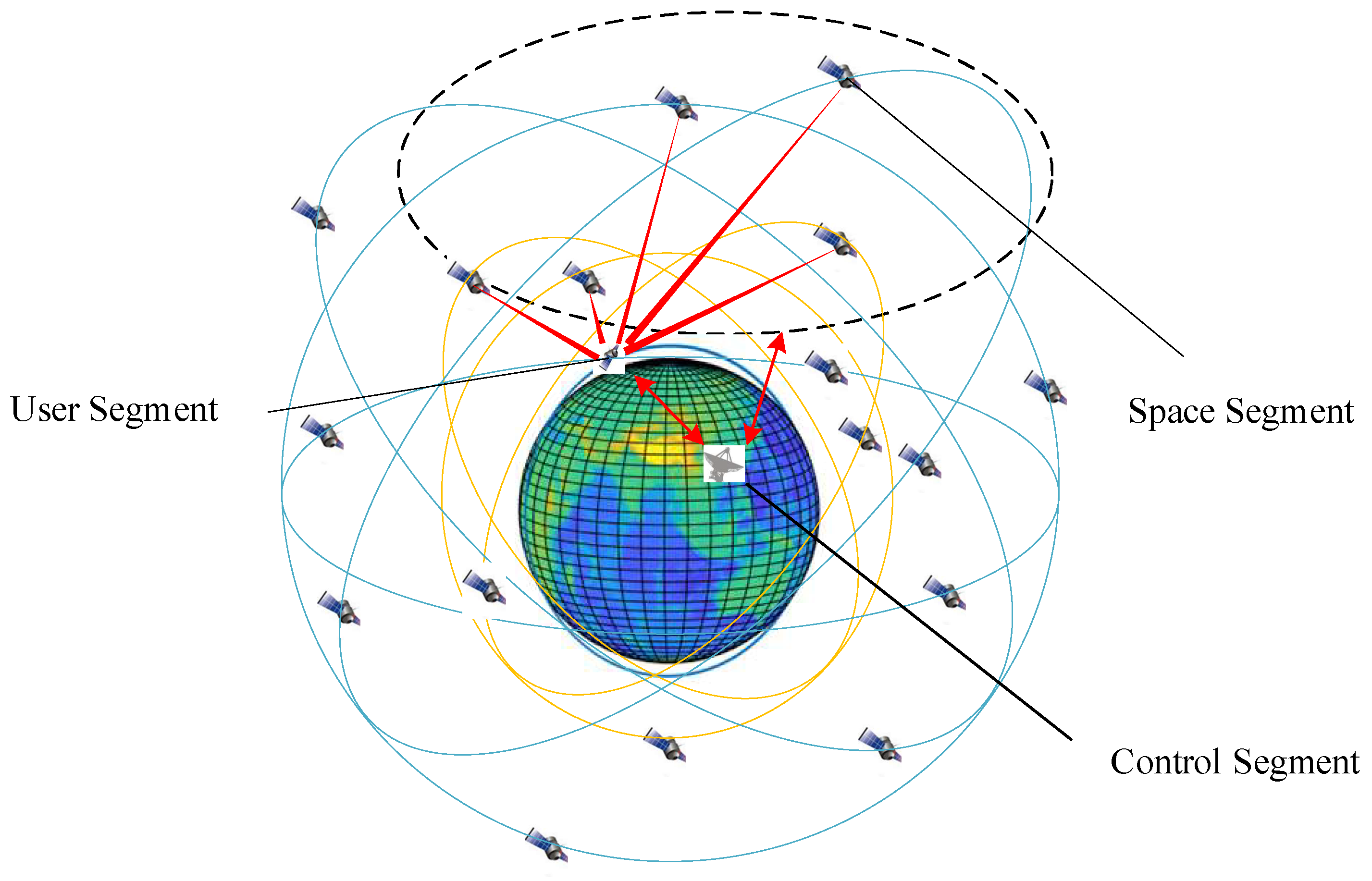
2. Basic Concepts of Cooperative Constellation Navigation System
2.1. Space Segment
2.2. User Segment
2.3. Control Segment
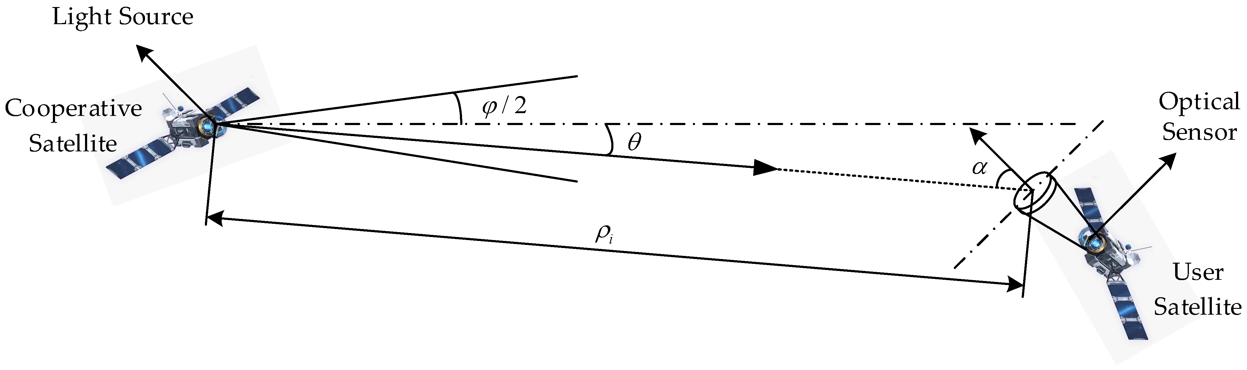
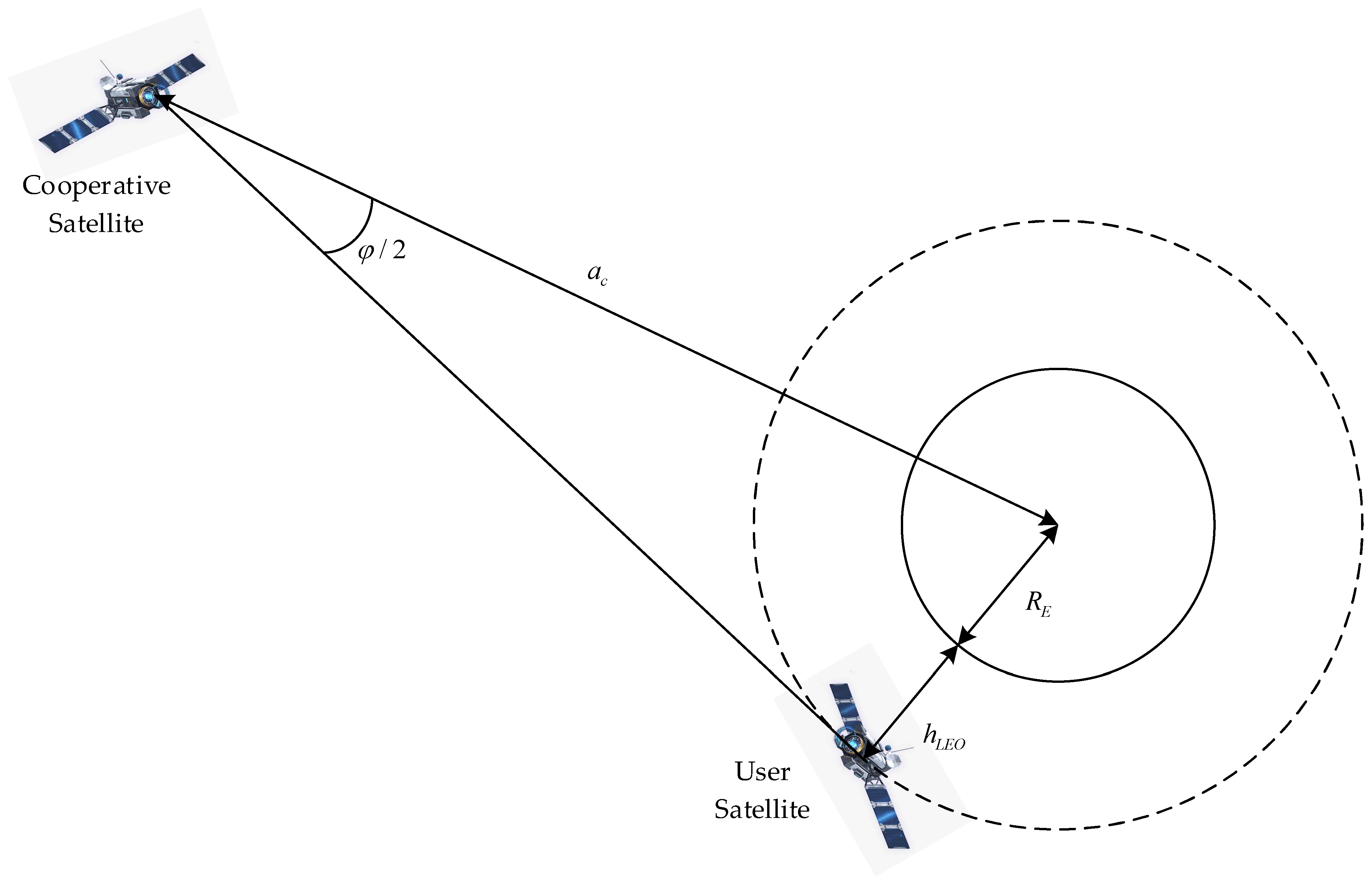
3. Analysis of Optical Transmission Link
3.1. Effective Optical Signals
3.2. Noise Analysis
3.2.1. Photon Noise
3.2.2. Dark Current Noise
3.2.3. Readout Noise
3.3. Signal to Noise Ratio
4. Orbit Determination Models
4.1. Orbital Dynamic Model
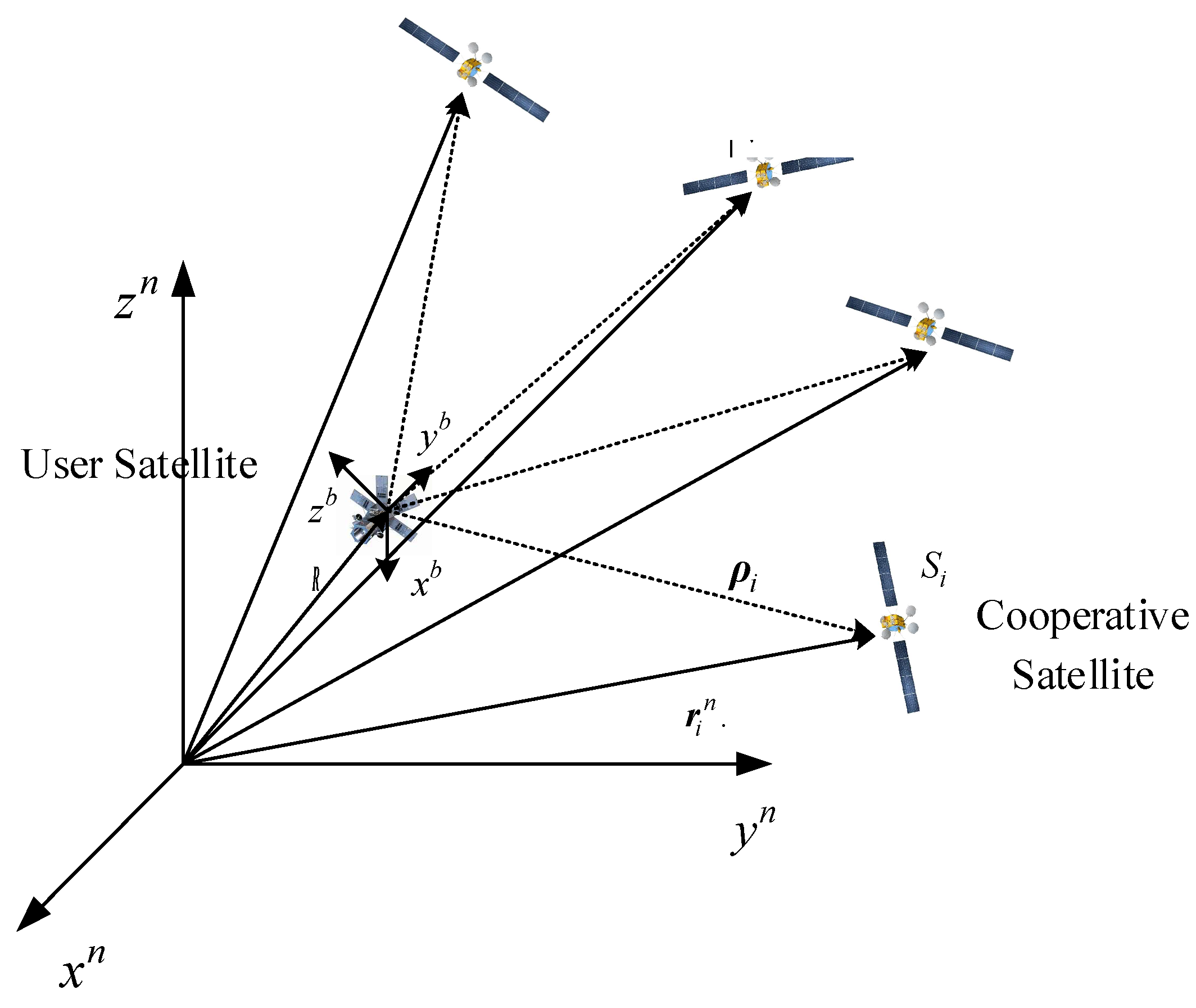
4.2. Observation Model Based on the Camera Imaging Model
4.3. Linearized Observation Model Based on LoS Vectors’ Inner Products
4.4. Position Accuracy Analysis Based on the Dilution of Precision
5. Navigation Algorithm Design
5.1. Single-Point Positioning Algorithm
| Algorithm 1. Single-point positioning algorithm. |
| Input: A series of pixel measurement , ephemeris of visible cooperative Satellites , and initial state |
| Output: Position vector of user satellite and its covariance matrix |
| 1: Initialize the corrected position with and initialize the iteration order with |
| 2: for do |
| 3: |
| 4: end for |
| 5: Generate the new real measurement using Equations (22) and (23) |
| 6: If then |
| 7: for do |
| 8: for do |
| 9: |
| 10: end for |
| 11: end for |
| 12: |
| 13: The measurement deviation |
| 14: Calculate the Jacobian matrix using Equations (24) and (27) |
| 15: Calculate the corrected position with |
| 16: |
| 17: |
| 18: Else |
| 19: Calculate the covariance matrix with |
| 20: |
| 21: Output the final estimated position and its covariance matrix |
| 22: end if |
5.2. Batch Dynamic Orbit Determination Algorithm
| Algorithm 2. Batch dynamic orbit determination algorithm. |
| Input: A time series of position vectors and covariance matrix obtained from Algorithm 1 Output: Initial orbital state |
| 1: Generate a series of positions and velocities with Equation (31) using third-order polynomial fitting |
| 2: Set initial state . Initialize the state correction with and initialize the iteration order with |
| 3: Calculate the stacked covariance matrix of observation noise using Equation (37) |
| 4: If then |
| 5: Generate a predicted position sequence using the orbital integrator 6: |
| 7: Generate a series for the state transition matrix |
| 8: |
| 9: Calculate the Jacobian matrix using Equations (34) and (36) |
| 10: Calculate the corrected position |
| 11: |
| 12: |
| 13: Else |
| 14: |
| 15: Output the estimated initial orbital state |
| 16: end if |
6. Simulation and Results
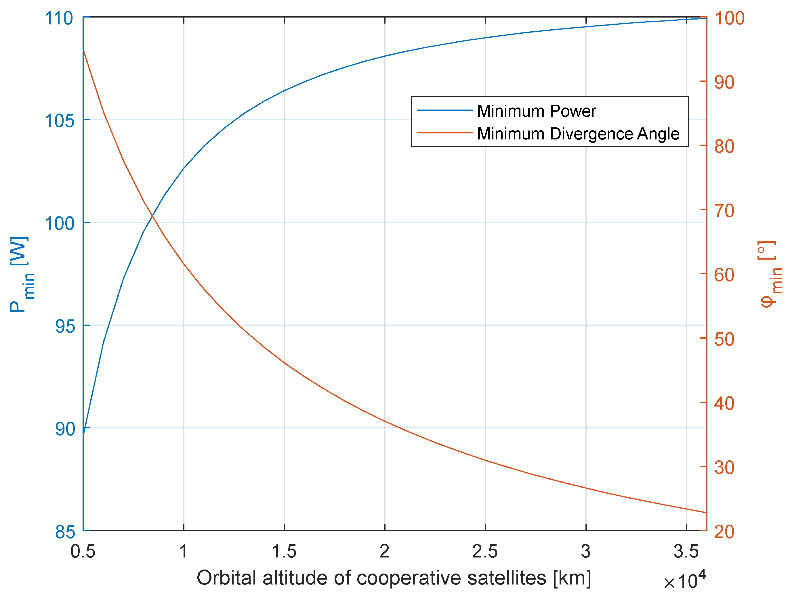
6.1. Optical Link Budget
6.2. Navigation Simulation Scenario
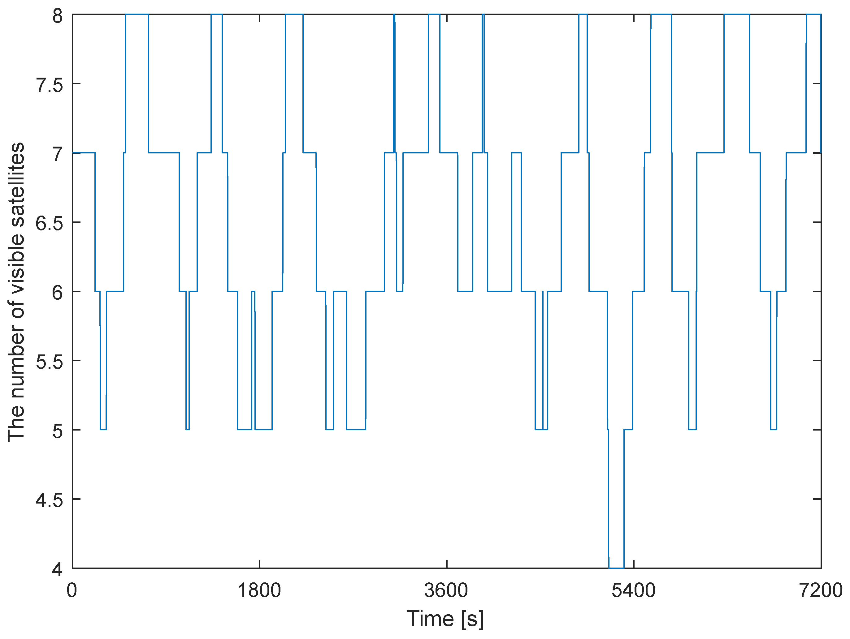
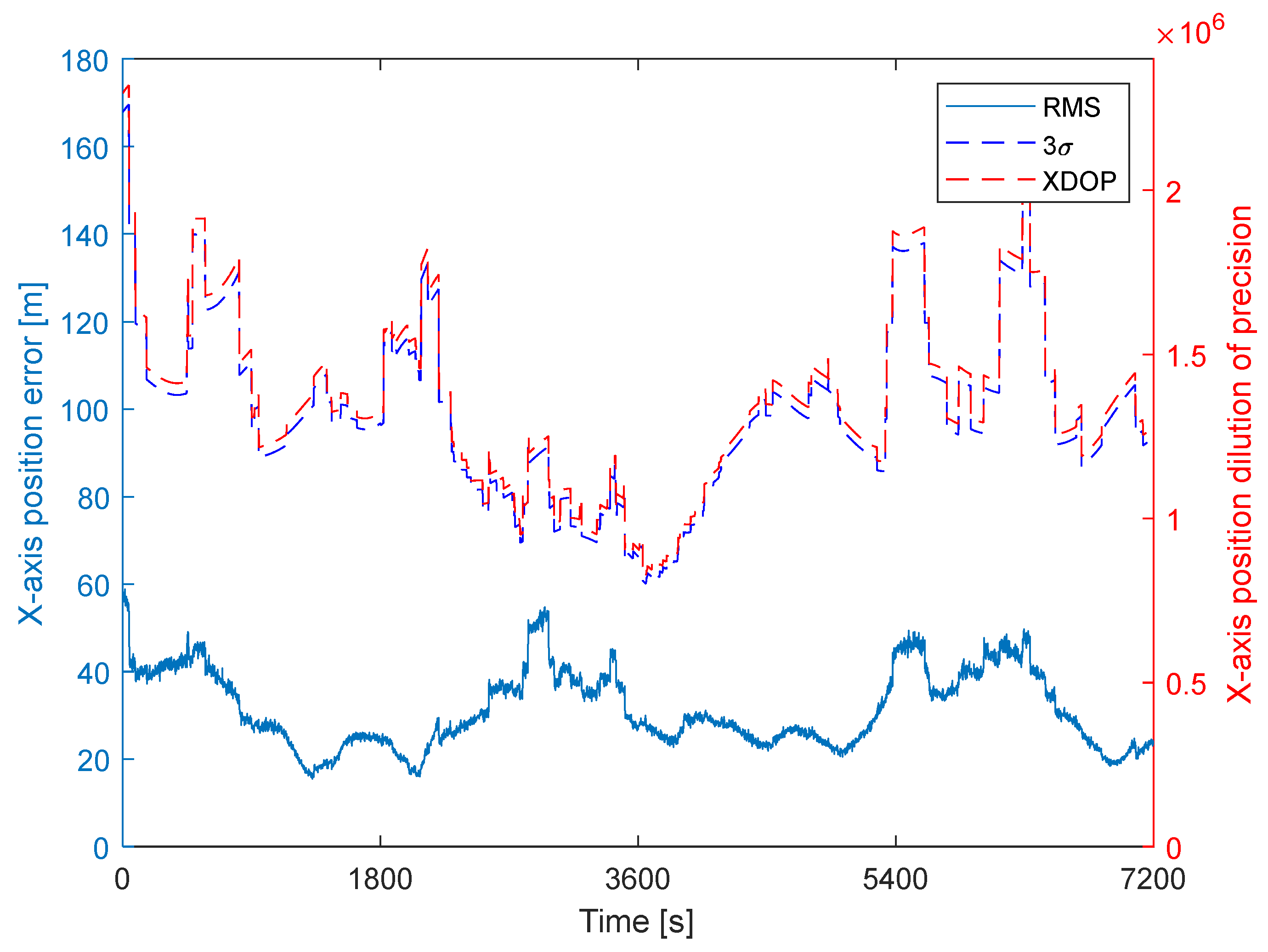
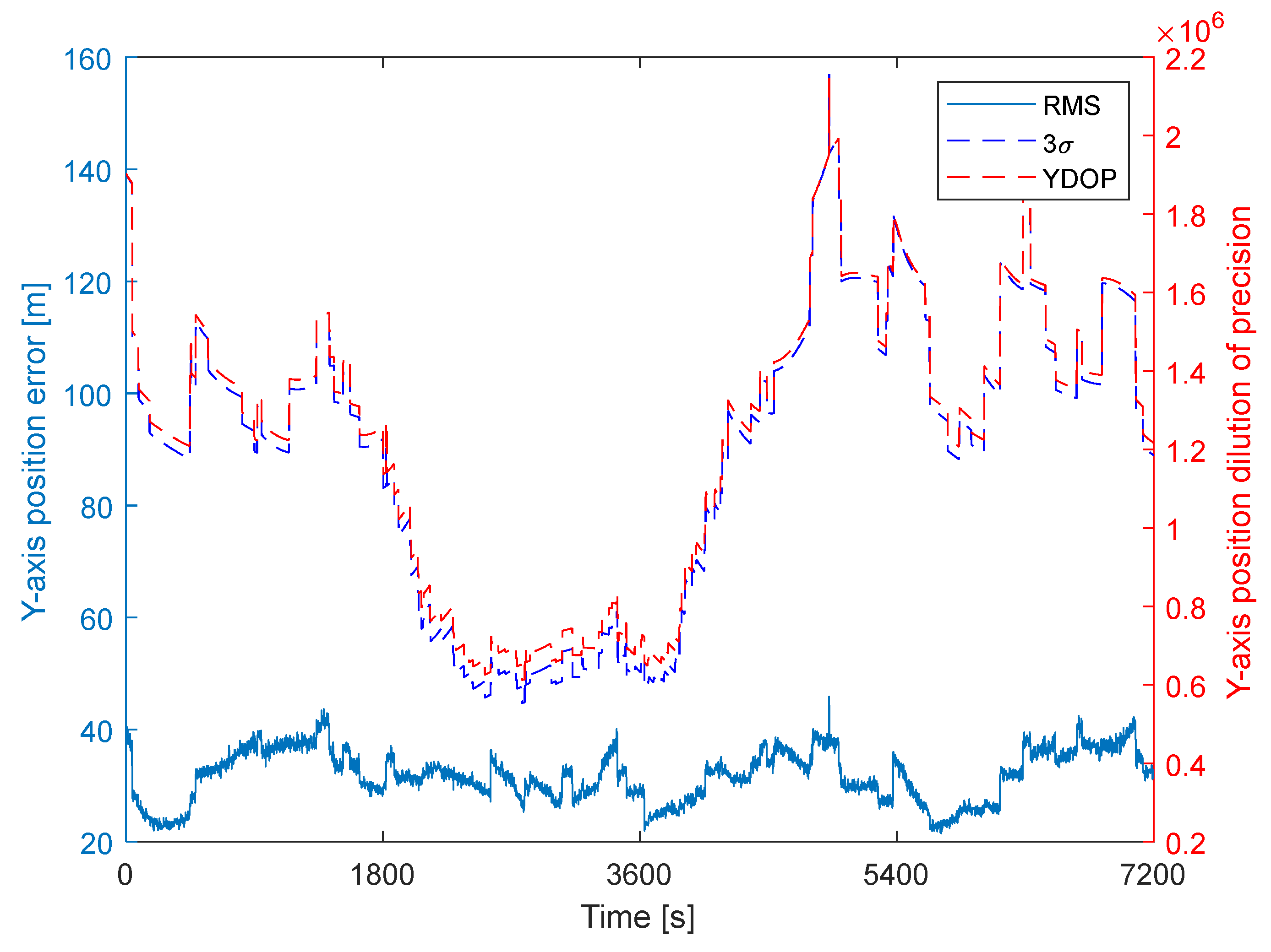
6.3. Baseline Case
6.4. Influence Factor Analysis
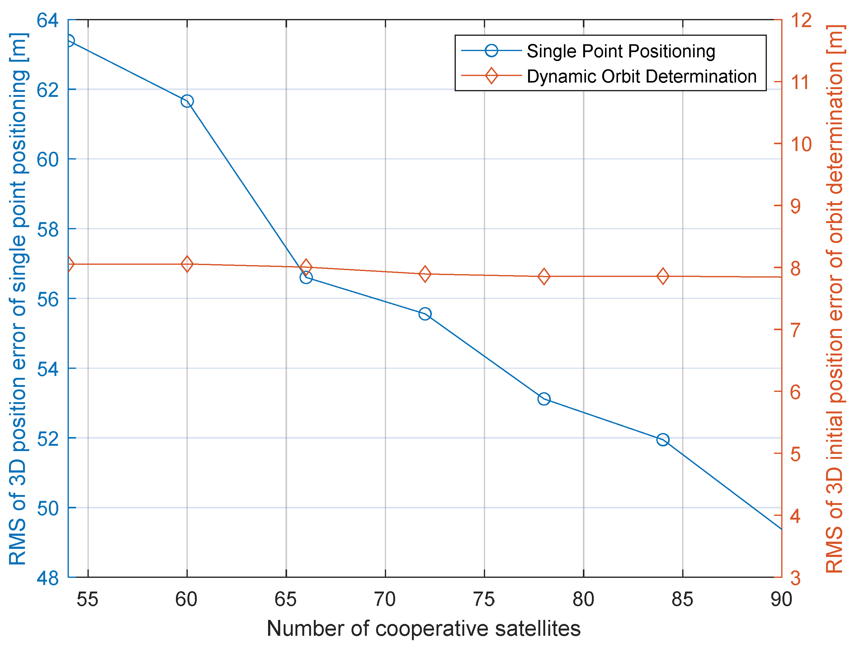
6.4.1. Cooperative Constellation Parameters
6.4.2. Ephemeris Errors of Cooperative Satellites
6.4.3. Noise Level of Measurement
- (1)
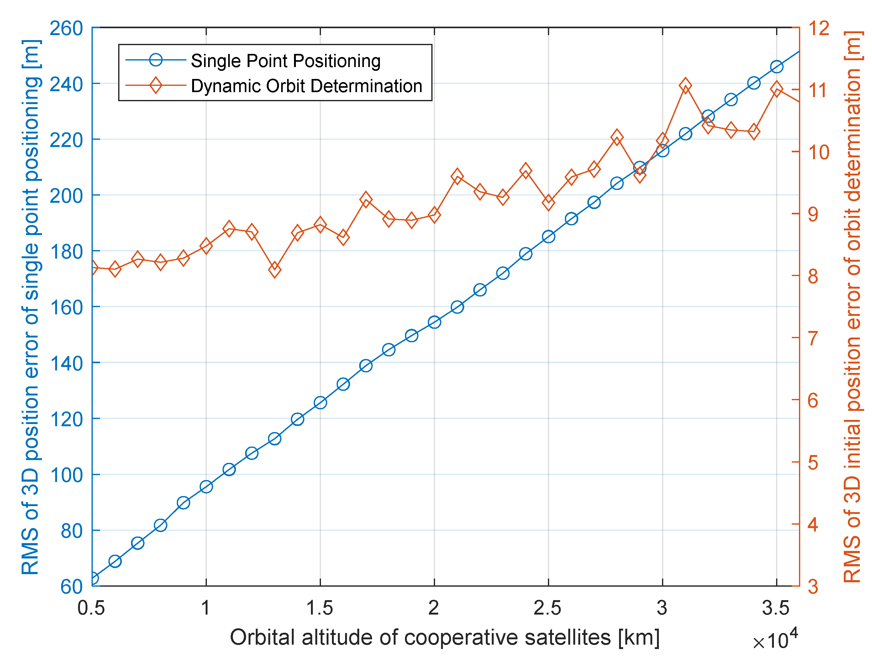
- For critical parameters of cooperative constellations, reducing the orbital altitude of cooperative satellites and increasing the number of cooperative satellites can improve navigation accuracy. The position accuracy increases slowly with an increase in the orbital plane number, and the constellation configuration number has little effect on navigation accuracy.
- (2)
- The ephemeris error of the cooperative satellite has little influence on navigation accuracy.
- (3)
- The optical measurement error is the main factor that affects navigation accuracy. Thus, it is vital to carry a dedicated optical sensor onboard the LEO satellite to realize accurate navigation.
- (4)
- After introducing the dynamic orbit determination method, the navigation accuracy of the navigation system is greatly improved, and the influence of external factors on navigation accuracy is greatly reduced.
- (5)
- The influence of Earth’s gravitational model errors on navigation accuracy is evident, as Earth’s gravitational model errors can significantly affect orbit propagation errors. Therefore, reducing dynamic model errors is of great importance in realizing high-precision orbit determination.
7. Conclusions
Author Contributions
Funding
Data Availability Statement
Conflicts of Interest
References
- Oliver, M.; Eberhard, G. Satellite Orbits; Springer: Berlin/Heidelberg, Germany; New York, NY, USA, 2000. [Google Scholar]
- ESA Space Debris Office. ESA’S Annual Space Environment Report, 2022; ESA: Paris, France, 2022. [Google Scholar]
- Montenbruck, O.; van Helleputte, T.; Kroes, R.; Gill, E. Reduced dynamic orbit determination using GPS code and carrier measurements. Aerosp. Sci. Technol. 2005, 9, 261–271. [Google Scholar] [CrossRef]
- Bock, H.; Jaggi, A.; Meyer, U.; Visser, P.; van den IJssel, J.; van Helleputte, T.; Heinze, M.; Hugentobler, U. GPS-derived orbits for the GOCE satellite. J. Geodesy 2011, 85, 807–818. [Google Scholar] [CrossRef]
- Tippenhauer, N.O.; Popper, C.; Rasmussen, K.B.; Capkun, S. On the requirements for successful GPS spoofing attacks. In Proceedings of the ACM Conference on Computer & Communications Security, Chicago, IL, USA, 17–21 October 2011; p. 75. [Google Scholar]
- Ning, X.L.; Fang, J.C. An autonomous celestial navigation method for LEO satellite based on unscented Kalman filter and information fusion. Aerosp. Sci. Technol. 2007, 11, 222–228. [Google Scholar] [CrossRef]
- Ning, X.L.; Wang, L.H.; Bai, X.B.; Fang, J.C. Autonomous satellite navigation using starlight refraction angle measurements. Adv. Space Res. 2013, 51, 1761–1772. [Google Scholar] [CrossRef]
- Qian, H.M.; Sun, L.; Cai, J.N.; Huang, W. A starlight refraction scheme with single star sensor used in autonomous satellite navigation system. Acta Astronaut. 2014, 96, 45–52. [Google Scholar] [CrossRef]
- Xu, C.; Wang, D.Y.; Huang, X.Y. Landmark-based autonomous navigation for pinpoint planetary landing. Adv. Space Res. 2016, 58, 2313–2327. [Google Scholar] [CrossRef]
- Zhu, S.Y.; Liu, D.C.; Liu, Y.; Cui, P.Y. Observability-based visual navigation using landmarks measuring angle for pinpoint landing. Acta Astronaut. 2018, 155, 313–324. [Google Scholar] [CrossRef]
- Ogawa, N.; Terui, F.; Yasuda, S.; Matsushima, K. Image-based Autonomous Navigation of Hayabusa2 using Artificial Landmarks: Design and In-Flight Results in Landing Operations on Asteroid Ryugu. In Proceedings of the AIAA Scitech 2020 Forum, Orlando, FL, USA, 6–10 January 2020. [Google Scholar] [CrossRef]
- Psiaki, M.L. Absolute Orbit and Gravity Determination Using Relative Position Measurements Between Two Satellites. J. Guid. Control Dyn. 2011, 34, 1285–1297. [Google Scholar] [CrossRef]
- Luo, Y.; Qin, T.; Zhou, X.Y. Observability Analysis and Improvement Approach for Cooperative Optical Orbit Determination. Aerospace 2022, 9, 166. [Google Scholar] [CrossRef]
- Huang, J.; Lei, X.; Zhao, G.; Liu, L.; Li, Z.; Luo, H.; Sang, J. Short-Arc Association and Orbit Determination for New GEO Objects with Space-Based Optical Surveillance. Aerospace 2021, 8, 298. [Google Scholar] [CrossRef]
- Flohrer, T.; Krag, H.; Klinkrad, H.; Schildknecht, T. Feasibility of performing space surveillance tasks with a proposed space-based optical architecture. Adv. Space Res. 2011, 47, 1029–1042. [Google Scholar] [CrossRef]
- Hu, Y.P.; Bai, X.Z.; Chen, L.; Yan, H.T. A new approach of orbit determination for LEO satellites based on optical tracking of GEO satellites. Aerosp. Sci. Technol. 2018, 11, 222–228. [Google Scholar] [CrossRef]
- Bernhard, H.W.; Herbert, L.; Elmar, W. GNSS—Global Navigation Satellite Systems; Springer: Vienna, Austria, 2008; pp. 309–340. [Google Scholar]
- Luba, O.; Boyd, L.; Gower, A.; Crum, J. GPS III system operations concepts. IEEE Aerosp. Electron. Syst. Mag. 2005, 20, 10–18. [Google Scholar] [CrossRef]
- William, L.W. Methods in Experimental Physics; Elsevier: London, UK, 1989; pp. 213–289. [Google Scholar] [CrossRef]
- Anbarasi, K.; Hemanth, C.; Sangeetha, R.G. A review on channel models in free space optical communication systems. Opt. Laser Technol. 2017, 97, 161–171. [Google Scholar] [CrossRef]
- Baeza, V.M.; Lagunas, E.; Al-Hraishawi, H.; Chatzinotas, S. An Overview of Channel Models for NGSO Satellites. In Proceedings of the IEEE 96th Vehicular Technology Conference, London, UK, 26–29 September 2022. [Google Scholar]
- Engstrom, R.W. Electro-Optics Handbook; FDA: Rockville, MD, USA, 1974. [Google Scholar]
- Bar-Shalom, Y.; Li, R.; Kirubarajan, T. Estimation with Applications to Tracking and Navigation: Theory Algorithms and Software; John Wiley & Sons: Hoboken, NJ, USA, 2001. [Google Scholar]


| Acronym | Description |
|---|---|
| LEO | Low Earth orbit |
| LoS | Line of sight |
| GPS | The Global Positioning System |
| CCNS | Cooperative constellation navigation system |
| MEO | Medium Earth orbit |
| ILS | Iterated least squares |
| FOV | Field of view |
| SNR | Signal to noise ratio |
| ECI | The Earth centered inertial coordinate frame |
| DOP | Dilution of precision |
| RMS | Root mean square |
| OD | Orbit determination |
| Parameters | Value |
|---|---|
| Aperture, m | 0.2 |
| FOV of sensor array, ° | 150 |
| FOV of single sensor | 30 |
| Spectral transmittance | 0.56 |
| Array size, pixel | 1024 × 1024 |
| Fill factor pixel | 0.44 |
| Quantum efficiency | 0.66 |
| Integration period, s | 0.02 |
| Dark current noise, e-/pixel-second | 3.5 |
| Readout noise, e- | 6 |
| Parameters | Value | |
|---|---|---|
| LEO satellite | Semi-major axis, km | 6878.14 |
| Eccentricity | 0.00074 | |
| Inclination, ° | 30 | |
| Right ascension of ascending node, ° | 210.1 | |
| Argument of perigee, ° | 8.2 | |
| Mean anomaly, ° | 215.8 | |
| Cooperative constellation | Inclination, ° | 55 |
| Satellite number | 54 | |
| Orbital plane number | 6 | |
| Constellation configuration number | 1 | |
| Direction | RMS of Position Errors, m | |||
|---|---|---|---|---|
| Single-Point Positioning | Dynamic Orbit Determination (The Degree and Order of the Earth’s Gravitational Model) | |||
| 8 × 8 | 20 × 20 | 60 × 60 | ||
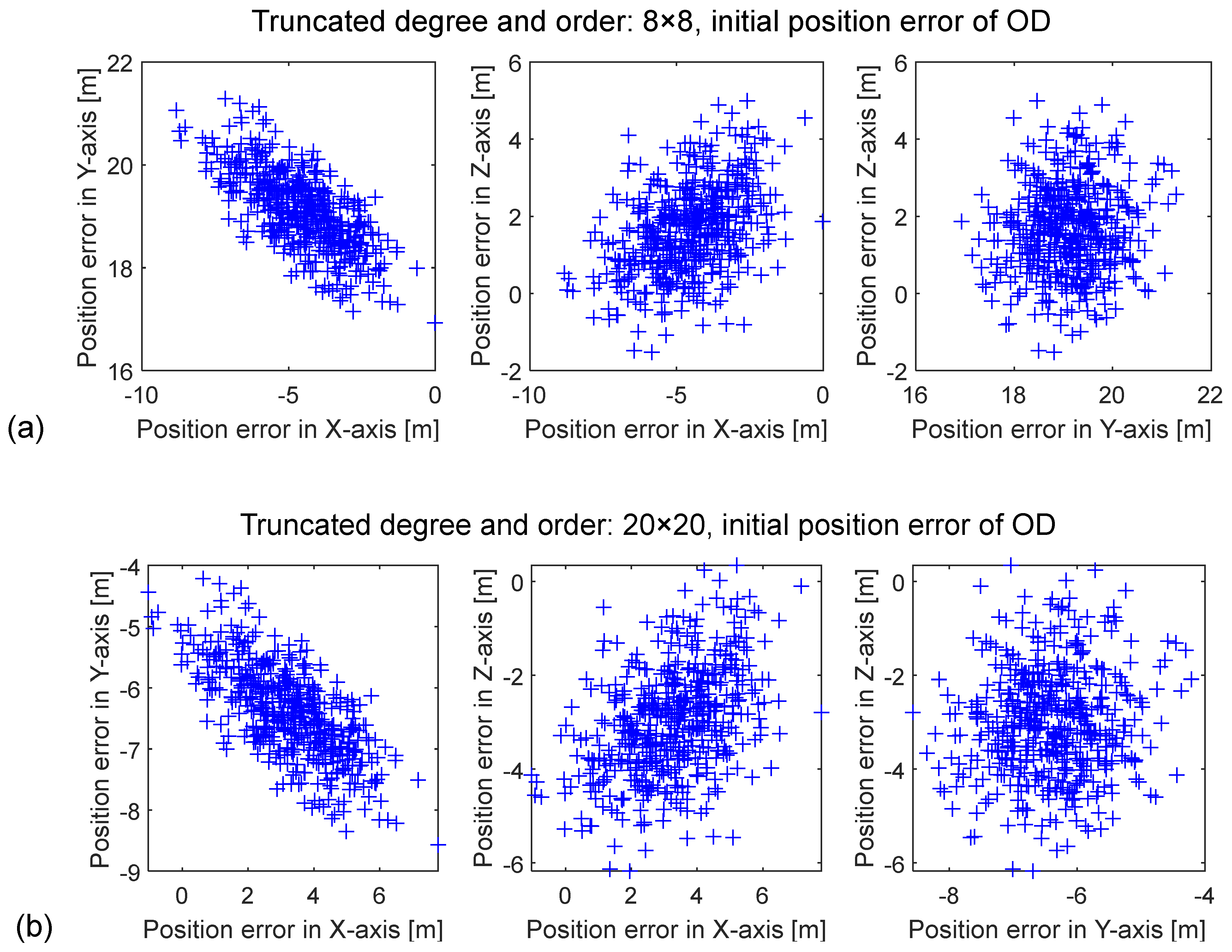
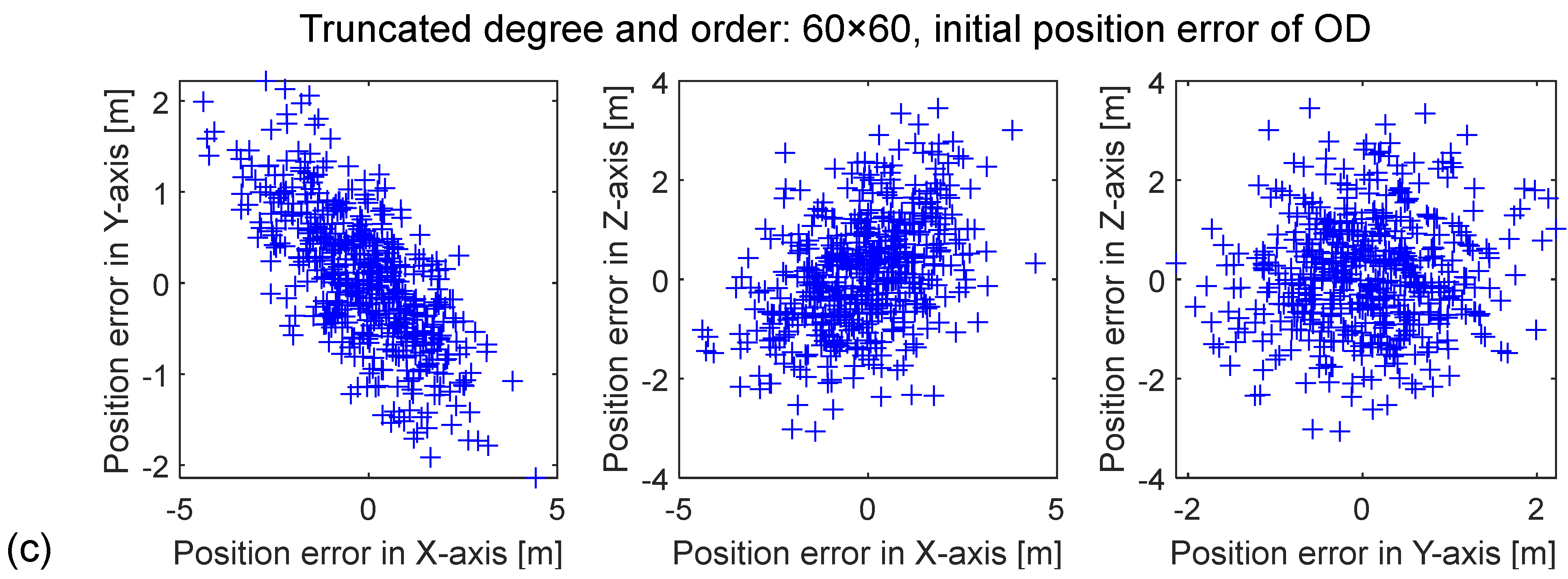
| 3D | 63.40 | 19.7616 | 8.0532 | 2.0006 |
| X-axis | 32.90 | 4.7296 | 3.5525 | 1.4577 |
| Y-axis | 32.49 | 19.0814 | 6.4748 | 0.7508 |
| Z-axis | 43.38 | 13.6106 | 3.2110 | 1.1462 |
| Orbital Plane Number | RMS of 3D Position Errors, m | |
|---|---|---|
| Single-Point Positioning | Dynamic Orbit Determination | |
| 3 | 74.33 | 8.2460 |
| 6 | 63.40 | 8.0532 |
| 9 | 58.58 | 7.9018 |
| Constellation Configuration Number | RMS of 3D Position Errors, m | |
|---|---|---|
| Single-Point Positioning | Dynamic Orbit Determination | |
| 1 | 63.40 | 8.0532 |
| 1.5 | 65.79 | 8.0263 |
| 2 | 64.52 | 7.8947 |
| Ephemeris Errors of Cooperative Satellites, m | RMS of 3D Position Errors, m | |
|---|---|---|
| Single-Point Positioning | Dynamic Orbit Determination | |
| 0 | 62.80 | 8.0472 |
| 10 | 63.40 | 8.0532 |
| 50 | 75.65 | 8.1918 |
| 100 | 105.21 | 8.6188 |
| Measurement Noise, Arcsec | RMS of 3D Position Errors, m | |
|---|---|---|
| Single-Point Positioning | Dynamic Orbit Determination | |
| 5 | 63.40 | 8.0532 |
| 10 | 125.76 | 9.5117 |
| 15 | 188.39 | 11.0676 |
Disclaimer/Publisher’s Note: The statements, opinions and data contained in all publications are solely those of the individual author(s) and contributor(s) and not of MDPI and/or the editor(s). MDPI and/or the editor(s) disclaim responsibility for any injury to people or property resulting from any ideas, methods, instructions or products referred to in the content. |
© 2023 by the authors. Licensee MDPI, Basel, Switzerland. This article is an open access article distributed under the terms and conditions of the Creative Commons Attribution (CC BY) license (https://creativecommons.org/licenses/by/4.0/).
Share and Cite
Chen, P.; Mao, X.; Chen, S. LEO Satellite Navigation Based on Optical Measurements of a Cooperative Constellation. Aerospace 2023, 10, 431. https://doi.org/10.3390/aerospace10050431
Chen P, Mao X, Chen S. LEO Satellite Navigation Based on Optical Measurements of a Cooperative Constellation. Aerospace. 2023; 10(5):431. https://doi.org/10.3390/aerospace10050431
Chicago/Turabian StyleChen, Pei, Xuejian Mao, and Siyu Chen. 2023. "LEO Satellite Navigation Based on Optical Measurements of a Cooperative Constellation" Aerospace 10, no. 5: 431. https://doi.org/10.3390/aerospace10050431
APA StyleChen, P., Mao, X., & Chen, S. (2023). LEO Satellite Navigation Based on Optical Measurements of a Cooperative Constellation. Aerospace, 10(5), 431. https://doi.org/10.3390/aerospace10050431