
IDDES Investigation of Rotor Blade Tip Vortices in Hovering State with Tip Slots
Abstract
:1. Introduction
2. Geometric Model, Computational Grid and Numerical Methodology
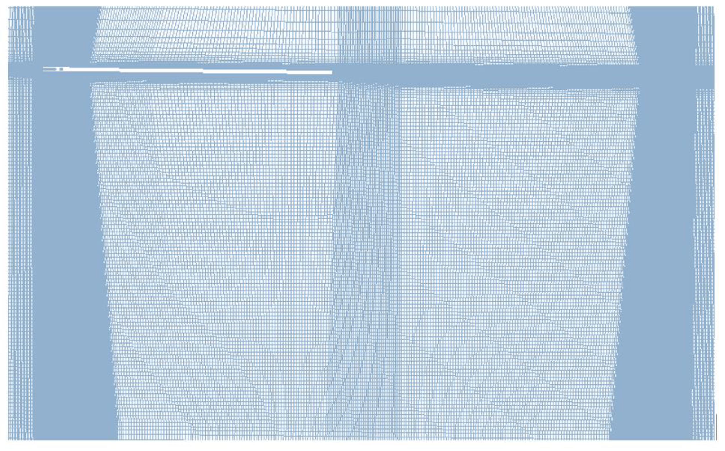
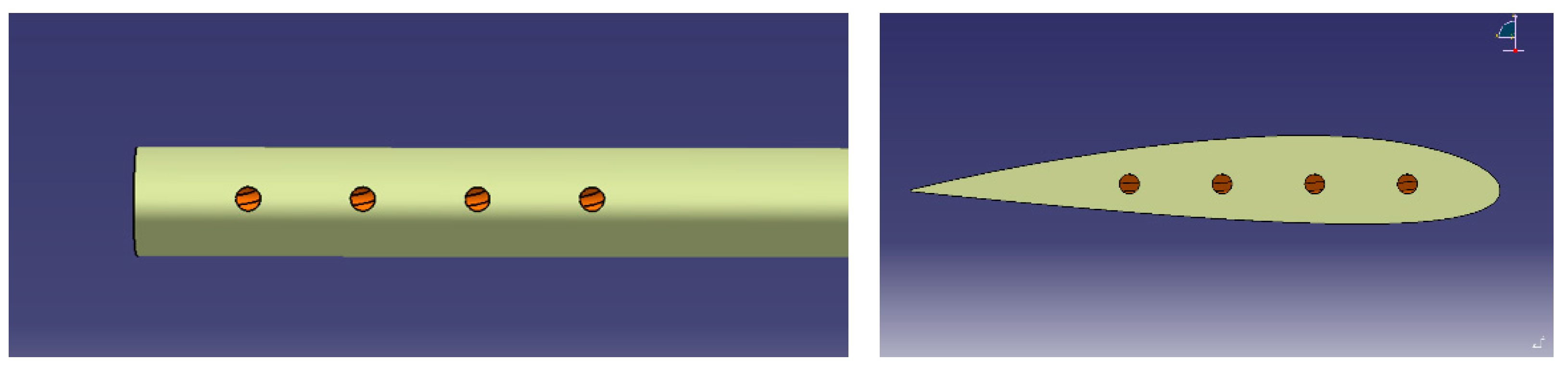
2.1. Geometric Model and Computational Grid
2.2. Numerical Methology
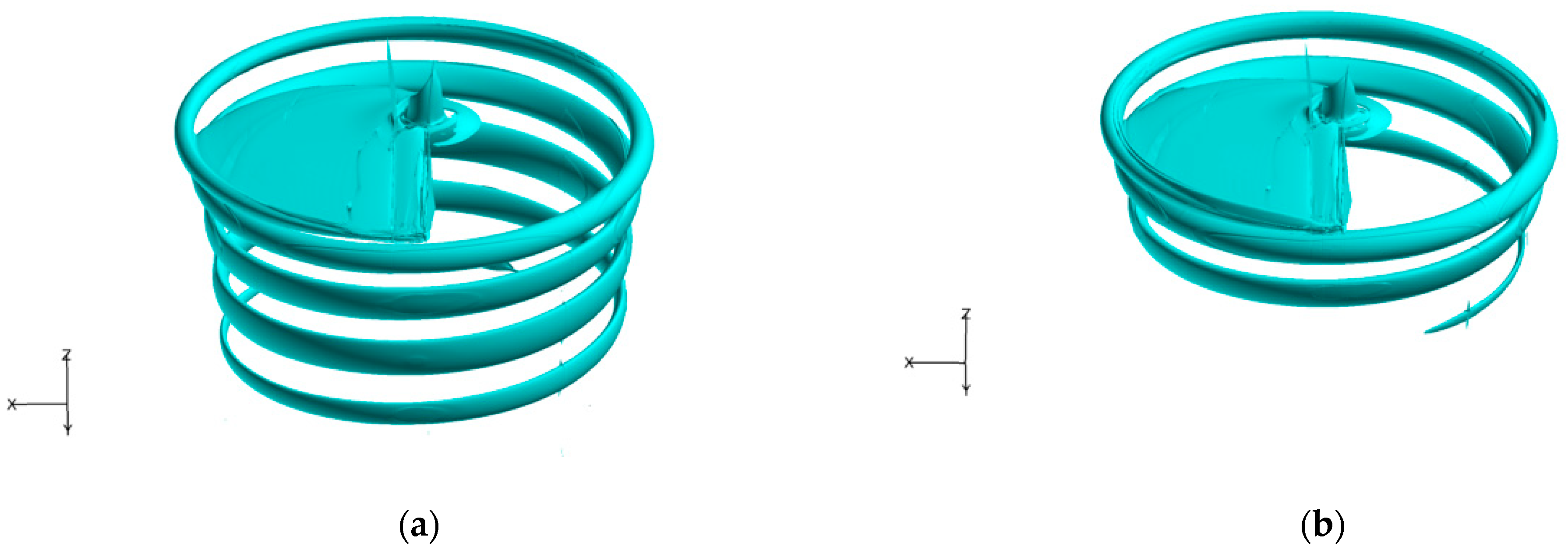
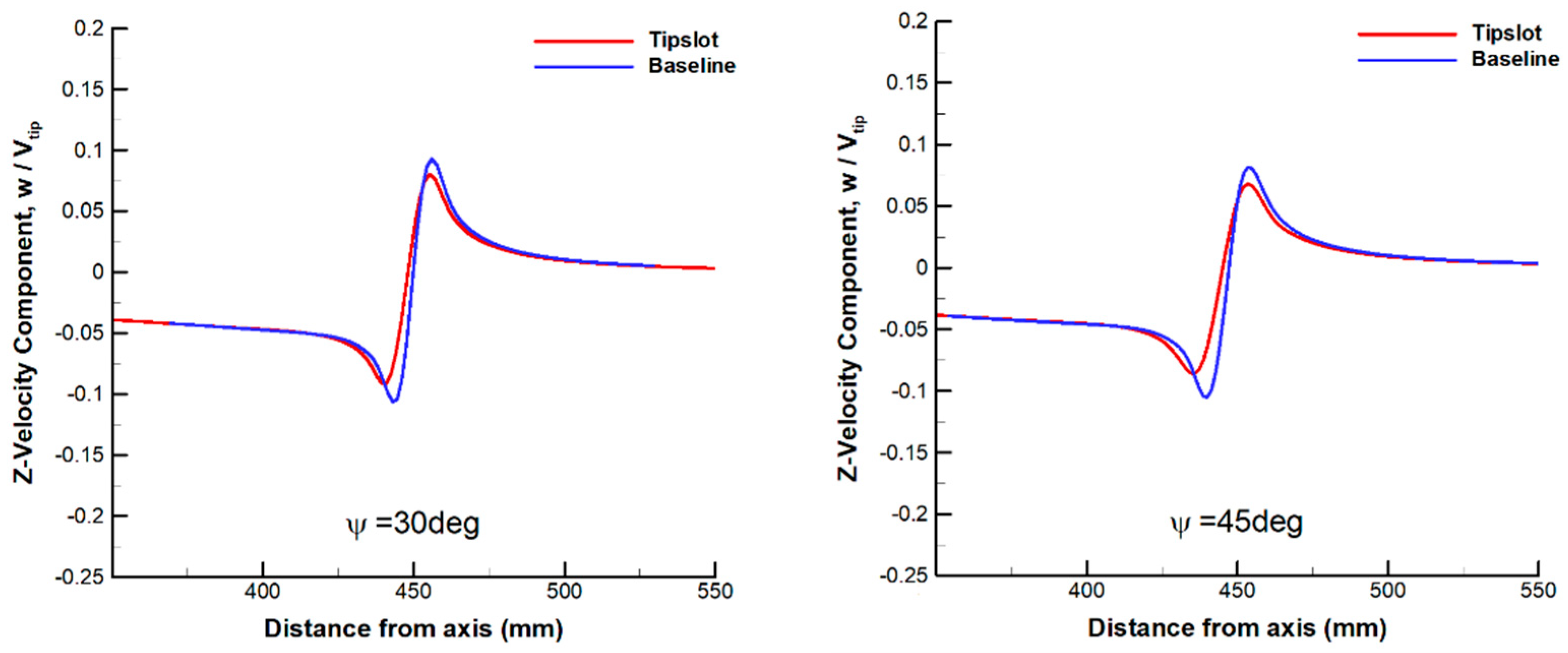
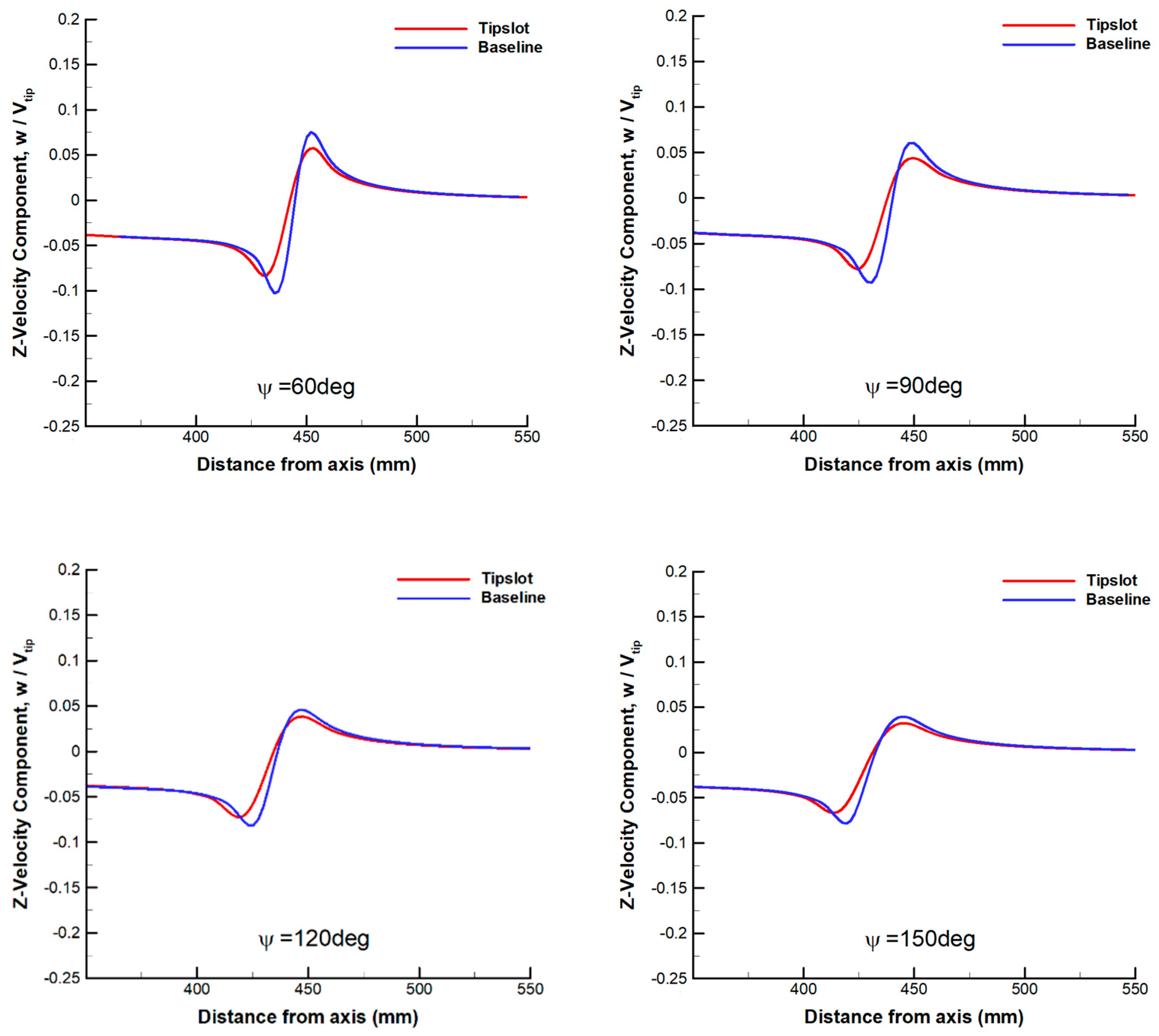
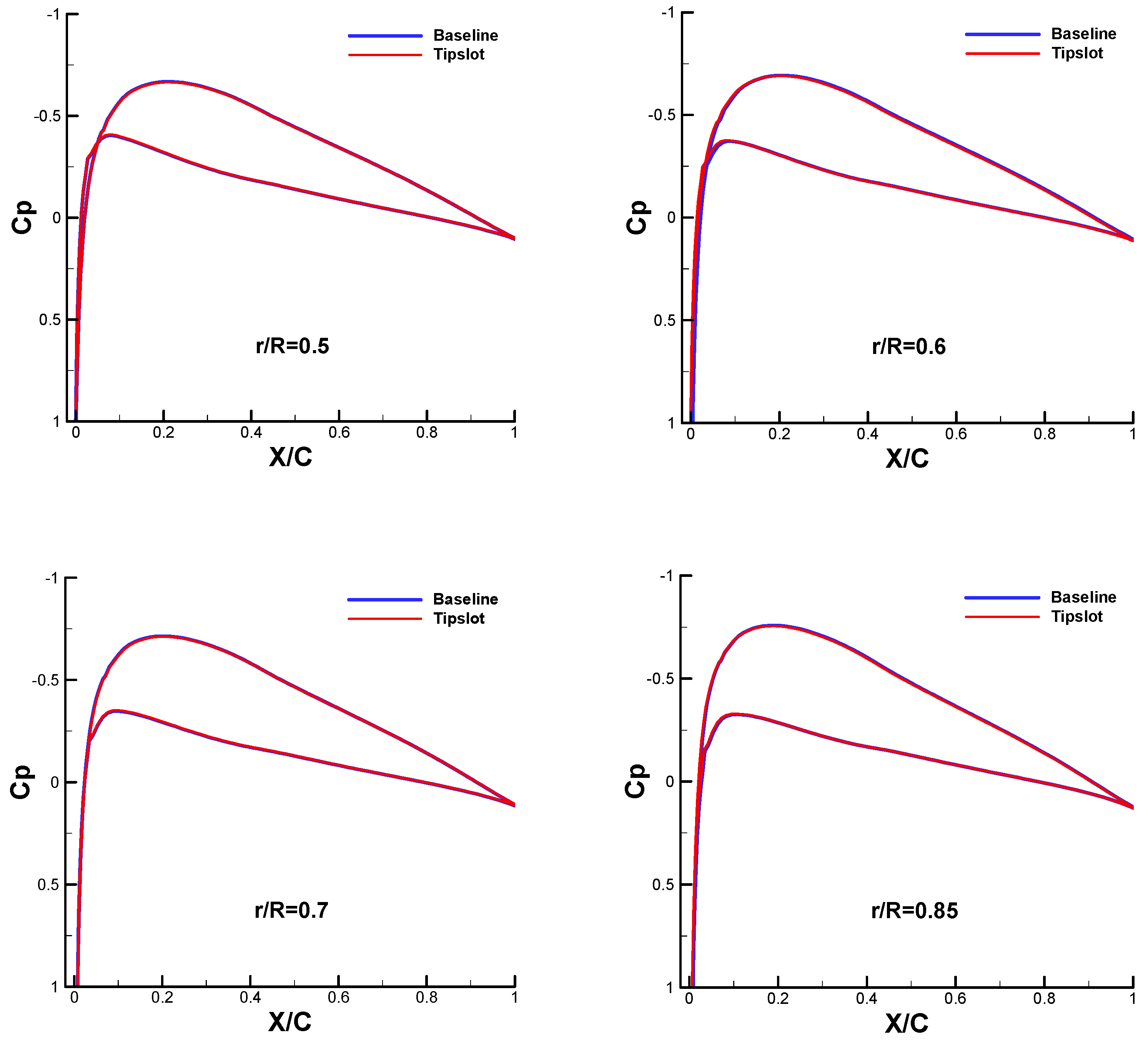
3. Comparison of Blade Tip Vortex Characteristics
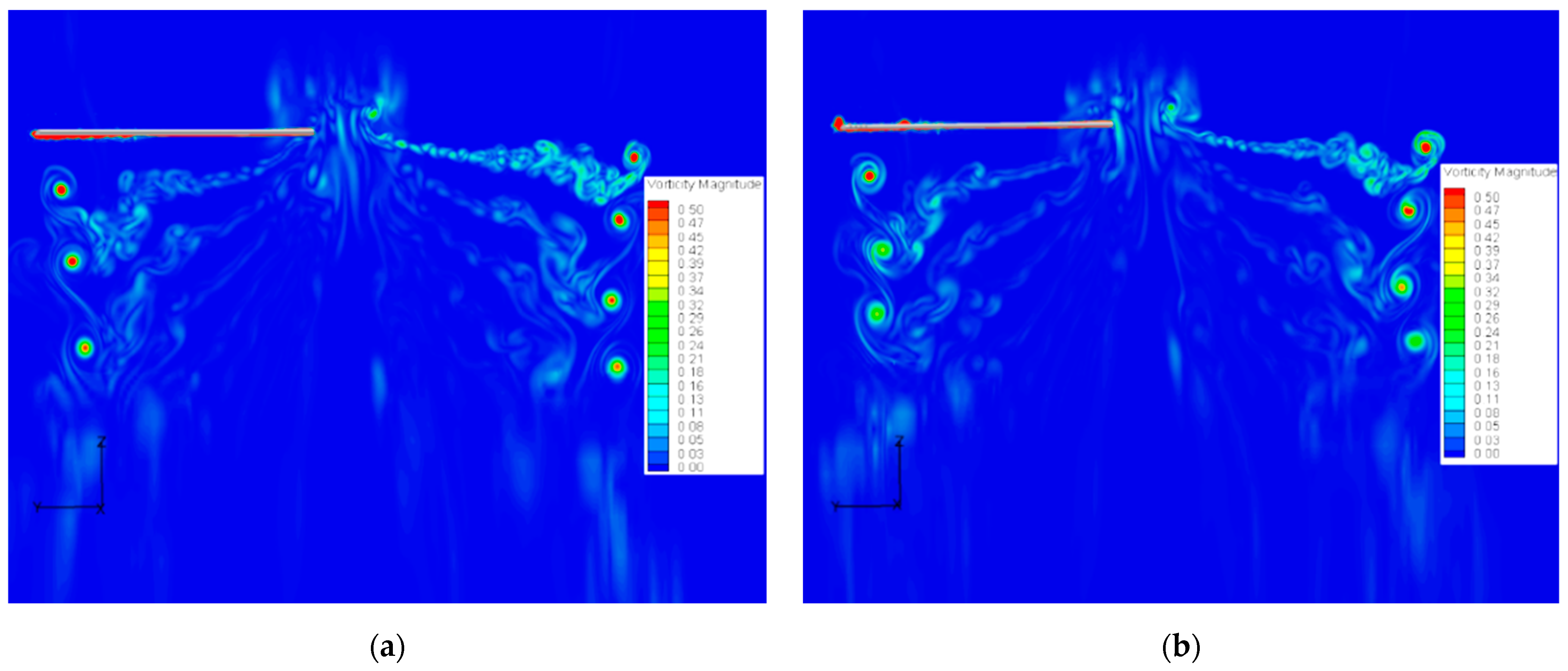
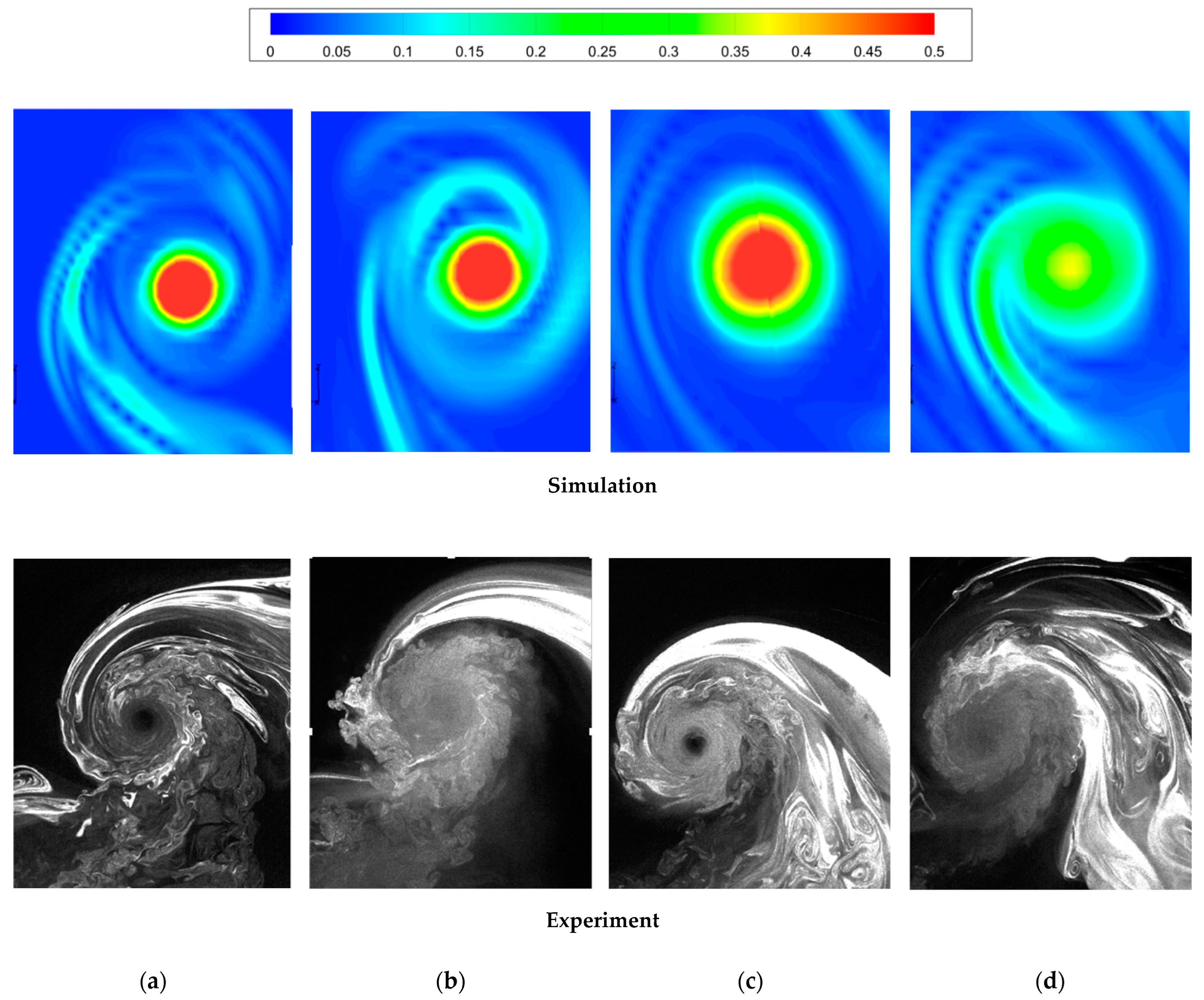
3.1. RANS Simulation
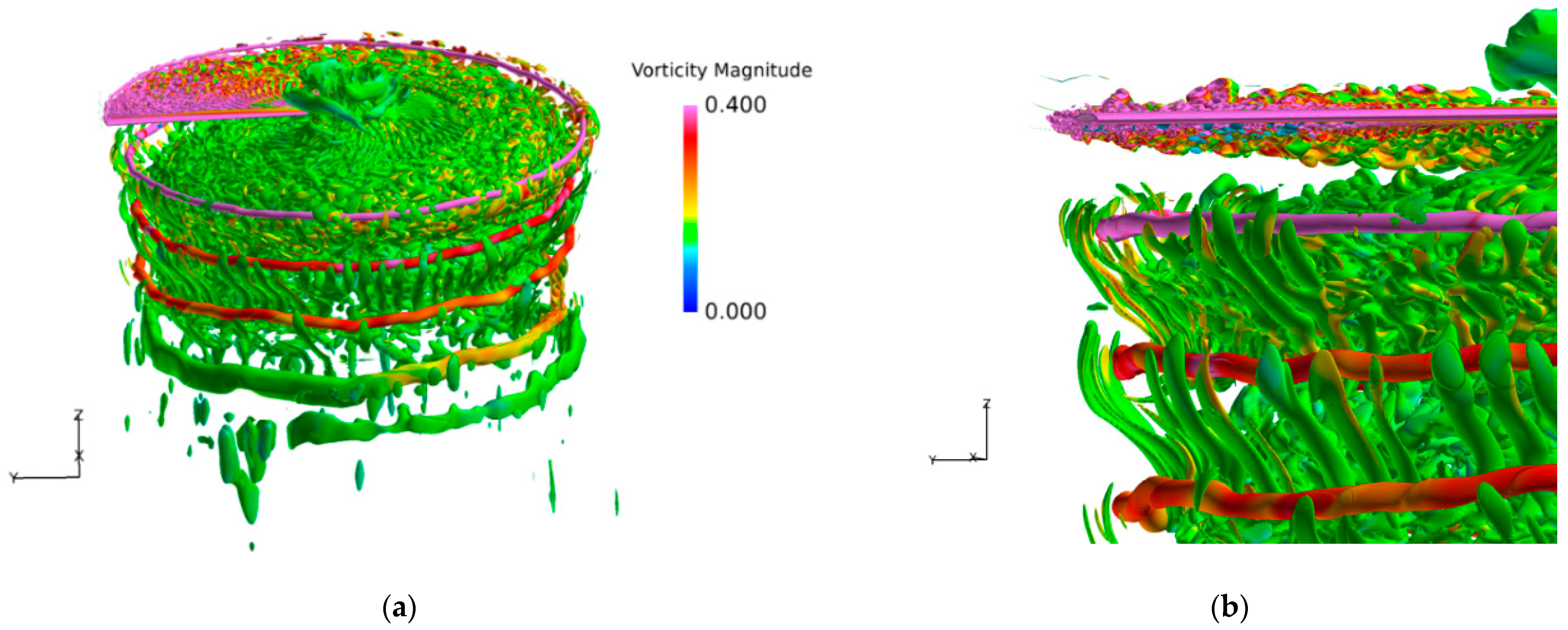
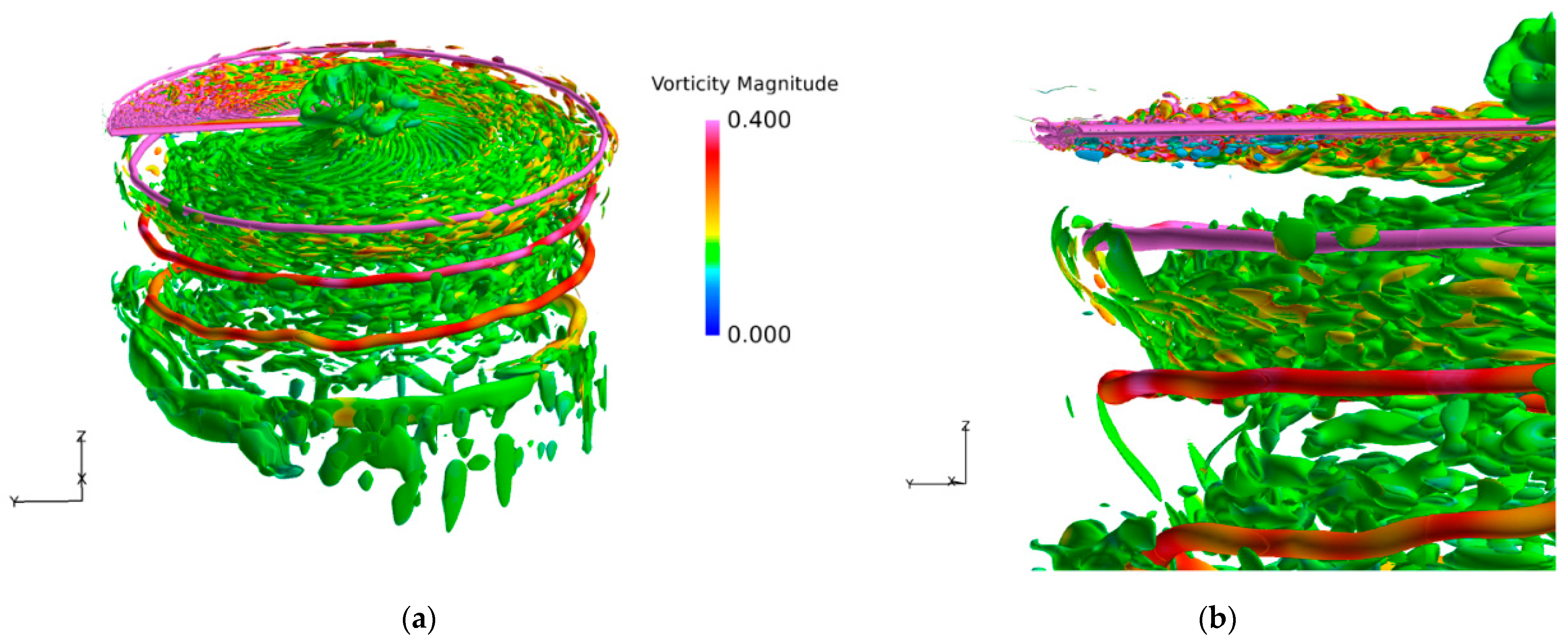
3.2. IDDES Simulation
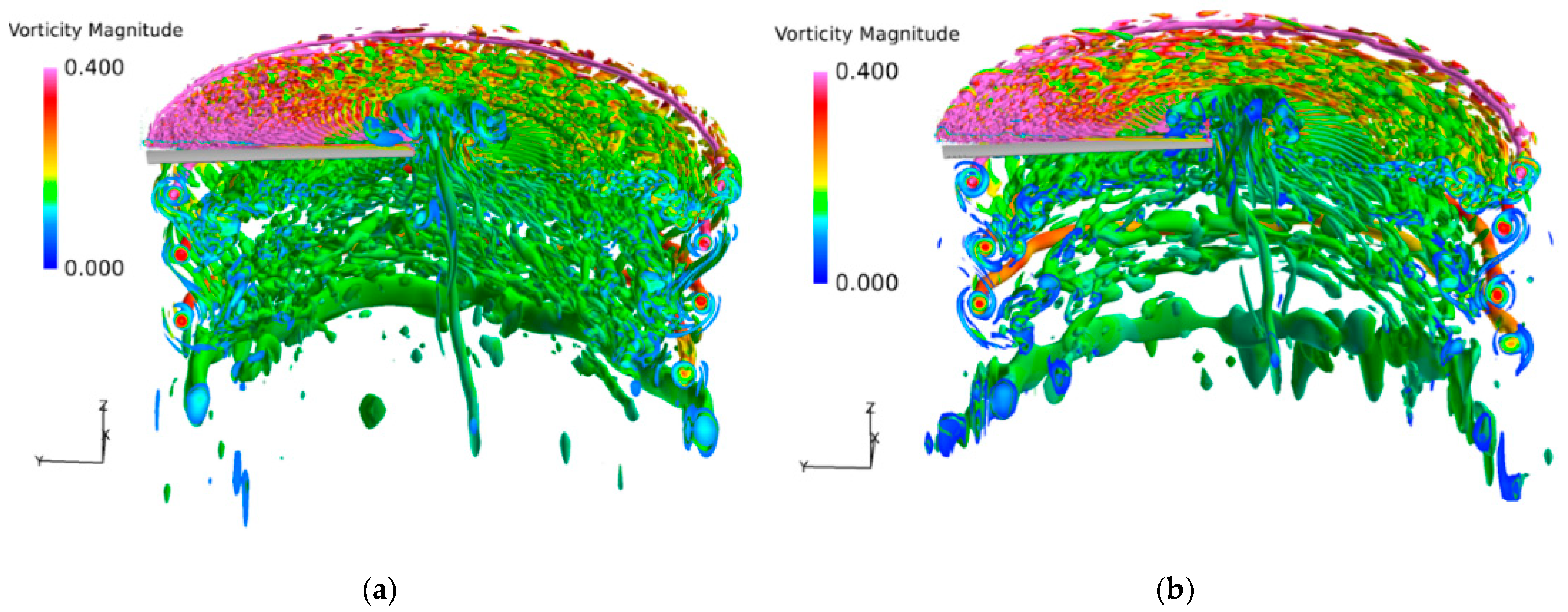
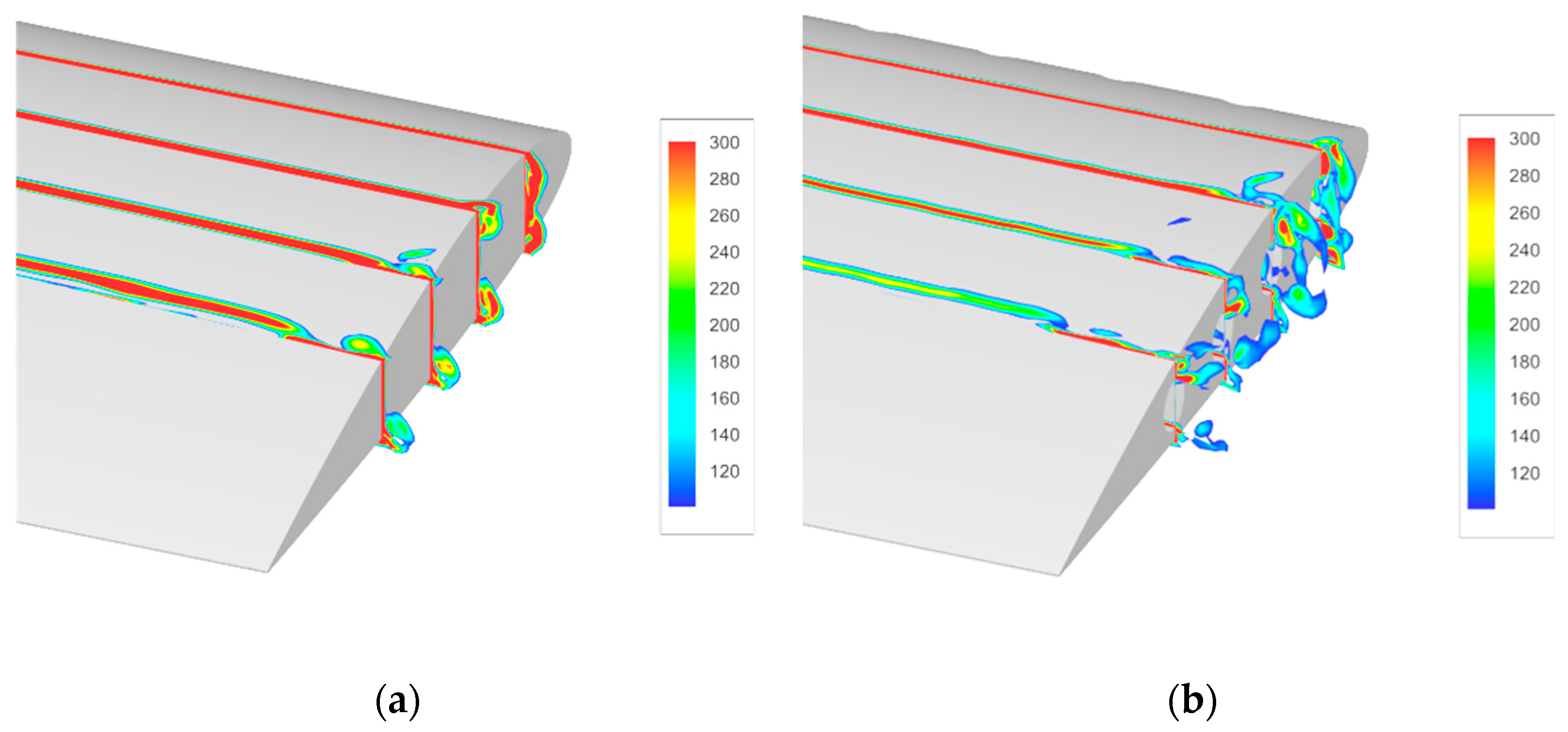
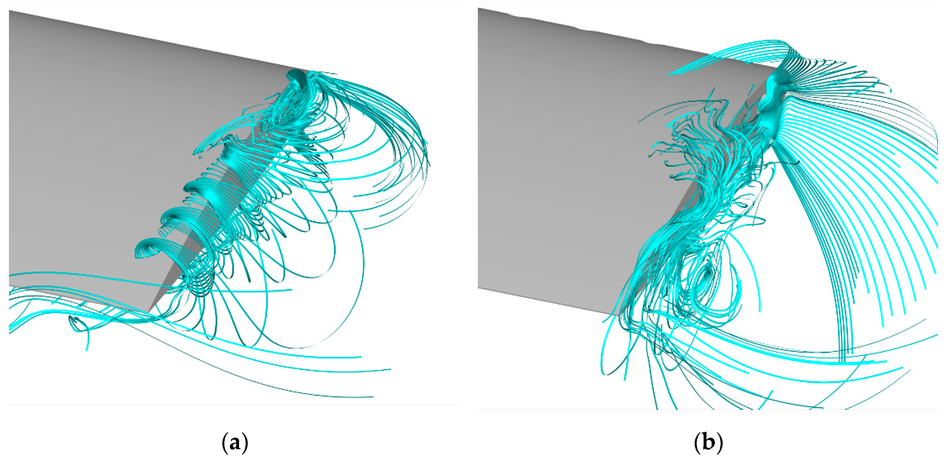
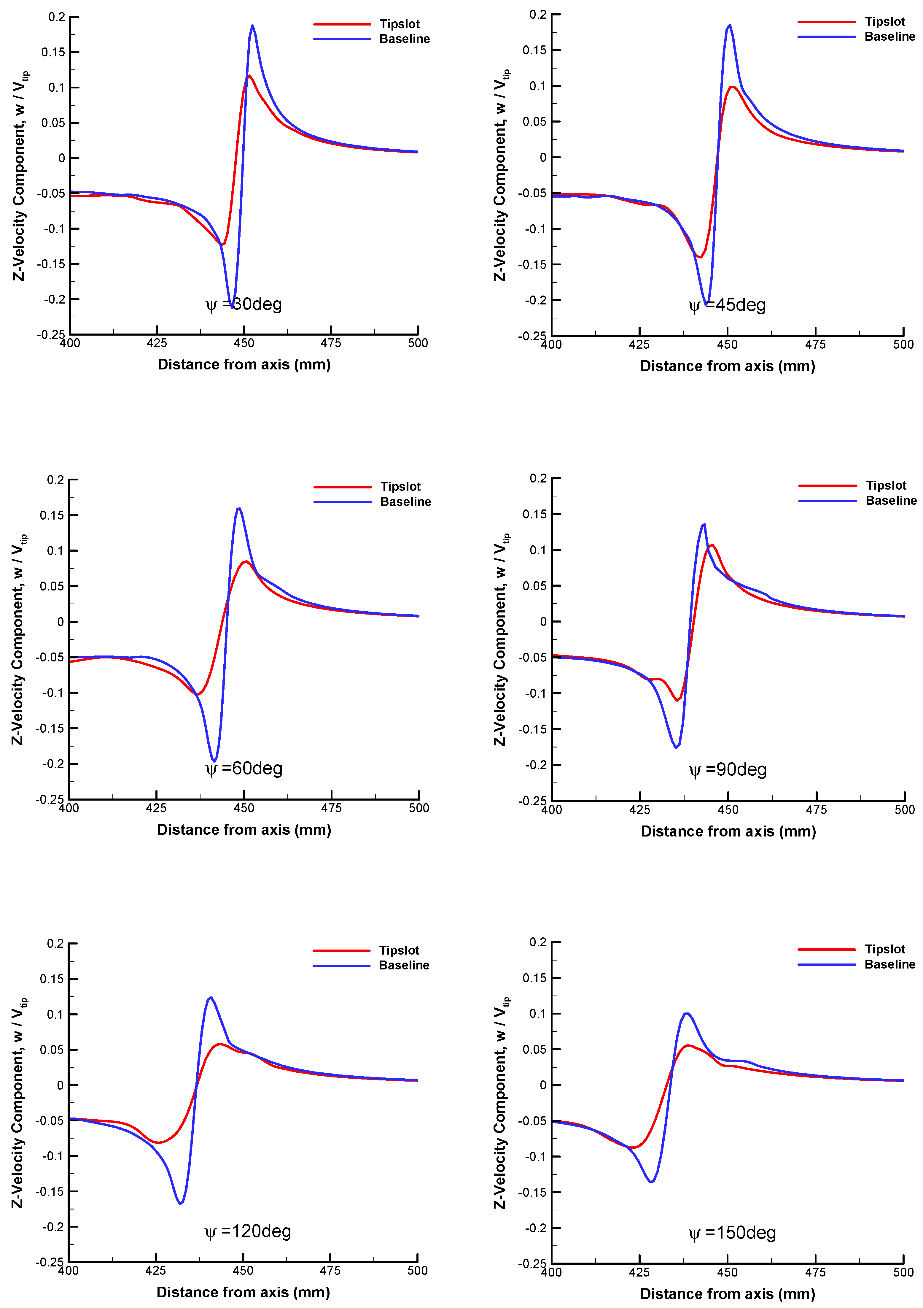
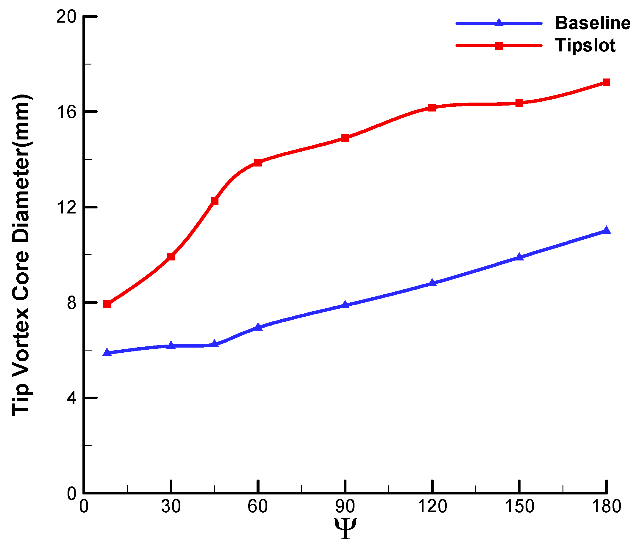
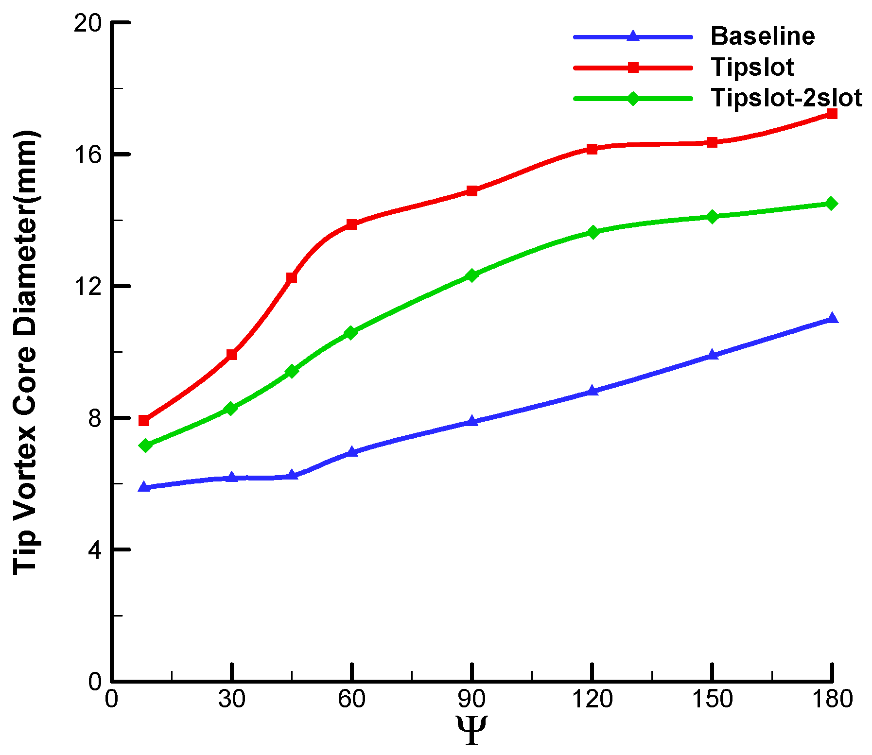
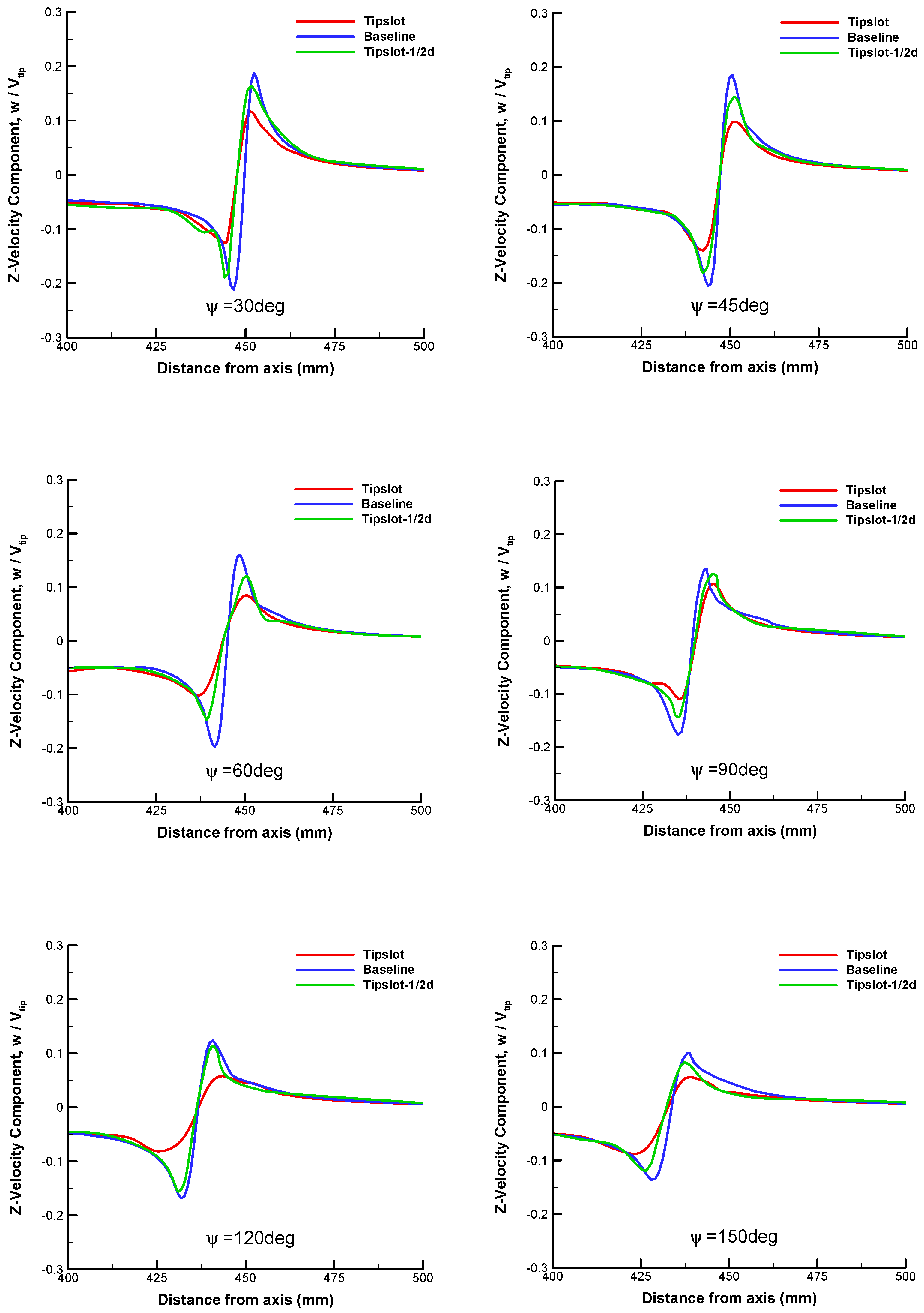
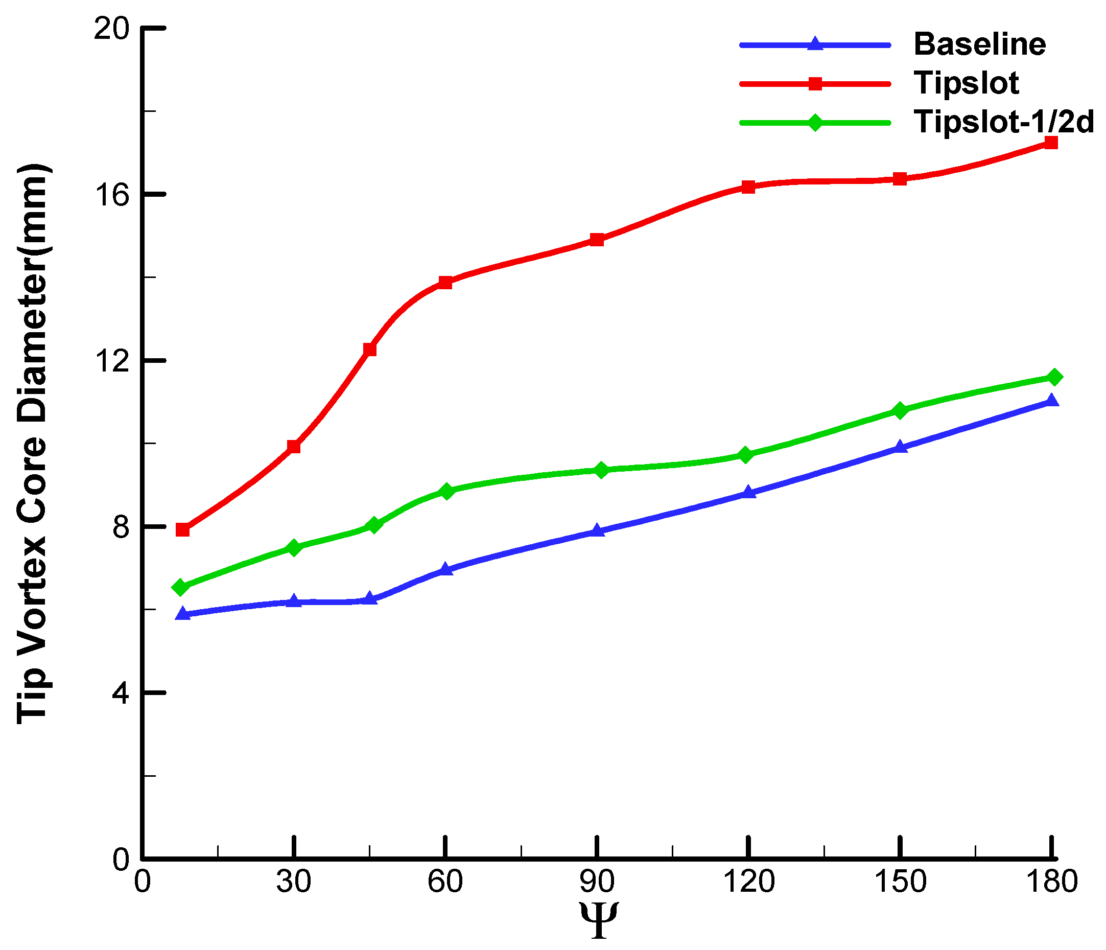
4. Investigation of the Effect of Slot Parameters
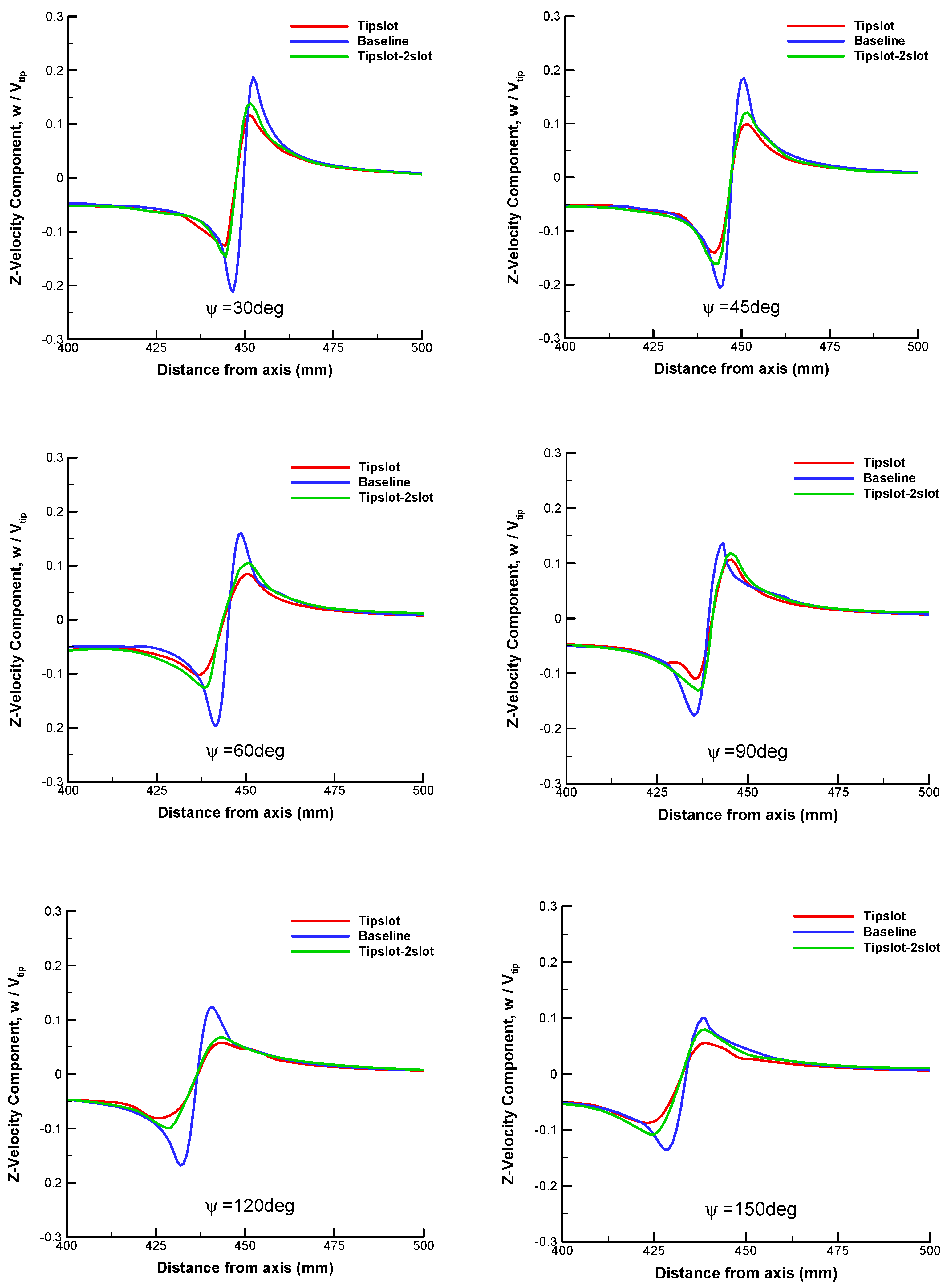
4.1. Slot Number
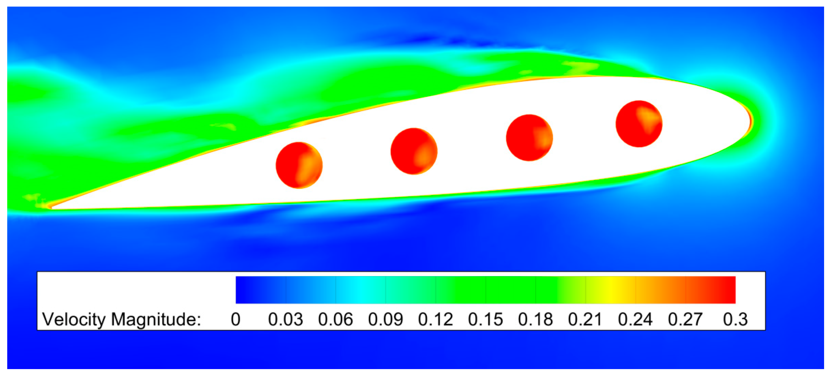
4.2. Slot Diameter
5. Conclusions
Author Contributions
Funding
Data Availability Statement
Conflicts of Interest
References
- Conlisk, A.T. Modern helicopter aerodynamics. Annu. Rev. Fluid Mech. 1997, 29, 515–567. [Google Scholar] [CrossRef]
- Conlisk, A.T. Modern helicopter rotor aerodynamics. Prog. Aerosp. Sci. 2001, 37, 419–476. [Google Scholar] [CrossRef]
- Yung, H.Y. Rotor blade–vortex interaction noise. Prog. Aerosp. Sci. 2000, 36, 97–115. [Google Scholar]
- Brocklehurst, A.; Barakos, G.N. A review of helicopter rotor blade tip shapes. Prog. Aerosp. Sci. 2013, 56, 35–74. [Google Scholar] [CrossRef]
- Kessler, C. Active rotor control for helicopters: Individual blade control and swashplateless rotor designs. CEAS Aeronaut. J. 2011, 1, 23–54. [Google Scholar] [CrossRef]
- Velez, C.; Ilie, M. Reduction of helicopter BVI noise using active flow control; the case of vortex street interactions. In Proceedings of the 18th AIAA/CEAS Aeroacoustics Conference, Honolulu, HI, USA, 27–30 June 2012; p. 2141. [Google Scholar]
- Le Pape, A.; Lienard, C.; Bailly, J. Active flow control for helicopters. Aerosp. Lab. 2013, 6, 1. [Google Scholar]
- Sun, Y.; Xu, G.; Shi, Y. Numerical investigation on noise reduction of rotor blade-vortex interaction using blade surface jet blowing. Aerosp. Sci. Technol. 2021, 116, 106868. [Google Scholar] [CrossRef]
- Sun, Y.; Xu, G.; Shi, Y. Parametric effect of blade surface blowing on the reduction of rotor blade–vortex interaction noise. J. Aerosp. Eng. 2022, 35, 4021110. [Google Scholar] [CrossRef]
- Syriac, J.S.; Vinod, N. Numerical Analysis and Reduction of Blade-Vortex Interaction (BVI) Noise in Helicopter Using Numerical Simulation. In Machines, Mechanism and Robotics; Springer: Singapore, 2022; pp. 547–553. [Google Scholar]
- Han, Y.O.; Leishman, J.G. Investigation of Helicopter Rotor-Blade-Tip-Vortex Alleviation Using a Slotted Tip. AIAA J. 2004, 42, 524–535. [Google Scholar] [CrossRef]
- Han, Y.O. Diffused tip vortex structure generated by a slotted tip rotor blade. In Proceedings of the 43rd AIAA Aerospace Sciences Meeting and Exhibit, Reno, NV, USA, 10–13 January 2005; p. 57. [Google Scholar]
- You, J.Y.; Kwon, O.J.; Han, Y.O. Viscous flow simulation of rotor blades with tip slots in hover. J. Am. Helicopter Soc. 2009, 54, 12006. [Google Scholar] [CrossRef]
- Hu, J.; Xu, G.; Shi, Y.; Huang, S. The influence of the blade tip shape on brownout by an approach based on computational fluid dynamics. Eng. Appl. Comput. Fluid Mech. 2021, 15, 692–711. [Google Scholar] [CrossRef]
- Spalart, P.R. Detached-eddy simulation. Annu. Rev. Fluid Mech. 2009, 41, 181–202. [Google Scholar] [CrossRef]
- Chaderjian, N.M.; Ahmad, J.U. Detached eddy simulation of the UH-60 rotor wake using adaptive mesh refinement. In Proceedings of the AHS International 68th Annual Forum, Fort Worth, TX, USA, 1–3 May 2012. [Google Scholar]
- Chaderjian, N.M. Advances in rotor performance and turbulent wake simulation using DES and adaptive mesh refinement. In Proceedings of the Seventh International Conference on Computational Fluid Dynamics (ICCFD7), Big Island, HI, USA, 9–13 July 2012. [Google Scholar]
- Yoon, S.; Pulliam, T.H.; Chaderjian, N.M. Simulations of XV-15 rotor flows in hover using OVERFLOW. In Proceedings of the Fifth Decennial AHS Aeromechanics Specialists’ Conference, San Francisco, CA, USA, 22–24 January 2014. [Google Scholar]
- Yoon, S.; Chaderjian, N.M.; Pulliam, T.H.; Holst, T.L. Effect of turbulence modeling on hovering rotor flows. In Proceedings of the 45th AIAA Fluid Dynamics Conference, Dallas, TX, USA, 22–26 June 2015; p. 2766. [Google Scholar]
- Shur, M.L.; Spalart, P.R.; Strelets, M.K.; Travin, A.K. A hybrid RANS-LES approach with delayed-DES and wall-modelled LES capabilities. Int. J. Heat Fluid Flow 2008, 29, 1638–1649. [Google Scholar] [CrossRef]
- Jiang, G.S.; Shu, C.W. Efficient implementation of weighted ENO schemes. J. Comput. Phys. 1996, 126, 202–228. [Google Scholar] [CrossRef] [Green Version]
- Van Leer, B. Towards the ultimate conservative difference scheme. V. A second-order sequel to Godunov’s method. J. Comput. Phys. 1979, 32, 101–136. [Google Scholar] [CrossRef]
- Jameson, A. Time dependent calculations using multigrid with applications to unsteady flows past airfoils and wings. In Proceedings of the 10th Computational Fluid Dynamics Conference, Honolulu, HI, USA, 24–26 June 1991. [Google Scholar]
- Menter, F.R. Two-equation eddy-viscosity turbulence models for engineering applications. AIAA J. 1994, 32, 1598–1605. [Google Scholar] [CrossRef] [Green Version]
- Shi, W.; Li, J.; Gao, H.; Zhang, H.; Yang, Z.; Jiang, Y. Numerical investigations on drag reduction of a civil light helicopter fuselage. Aerosp. Sci. Technol. 2020, 106, 106104. [Google Scholar] [CrossRef]
- Shi, W.; Zhang, H.; Li, Y. Enhancing the Resolution of Blade Tip Vortices in Hover with High-Order WENO Scheme and Hybrid RANS–LES Methods. Aerospace 2023, 10, 262. [Google Scholar] [CrossRef]
- Spalart, P.R.; Deck, S.; Shur, M.L.; Squires, K.; Streletsw, M.; Travin, A. A new version of detached-eddy simulation, resistant to ambiguous grid densities. Theor. Comput. Fluid Dyn. 2006, 20, 181–195. [Google Scholar] [CrossRef]


| Reynold Number (Re) | ||
|---|---|---|
| 0.26 | 4 deg |
| Method | Thrust Coefficient | Power Coefficient | Figure of Merit |
|---|---|---|---|
| Baseline blade–URANS | 0.00215 | 7.049 × 10⁻⁵ | 0.433 |
| Slotted-tip blade–URANS | 0.00209 | 6.756 × 10⁻⁵ | 0.421 |
| Baseline blade–IDDES | 0.00211 | 6.853 × 10⁻⁵ | 0.429 |
| Slotted-tip blade–IDDES | 0.00204 | 6.515 × 10⁻⁵ | 0.416 |
| Slot1 | Slot2 | Slot3 | Slot4 |
|---|---|---|---|
| 0.004104 | 0.004414 | 0.003921 | 0.003512 |
Disclaimer/Publisher’s Note: The statements, opinions and data contained in all publications are solely those of the individual author(s) and contributor(s) and not of MDPI and/or the editor(s). MDPI and/or the editor(s) disclaim responsibility for any injury to people or property resulting from any ideas, methods, instructions or products referred to in the content. |
© 2023 by the authors. Licensee MDPI, Basel, Switzerland. This article is an open access article distributed under the terms and conditions of the Creative Commons Attribution (CC BY) license (https://creativecommons.org/licenses/by/4.0/).
Share and Cite
Shi, W.; Zhang, H.; Li, Y. IDDES Investigation of Rotor Blade Tip Vortices in Hovering State with Tip Slots. Aerospace 2023, 10, 575. https://doi.org/10.3390/aerospace10070575
Shi W, Zhang H, Li Y. IDDES Investigation of Rotor Blade Tip Vortices in Hovering State with Tip Slots. Aerospace. 2023; 10(7):575. https://doi.org/10.3390/aerospace10070575
Chicago/Turabian StyleShi, Wenbo, Heng Zhang, and Yuanxiang Li. 2023. "IDDES Investigation of Rotor Blade Tip Vortices in Hovering State with Tip Slots" Aerospace 10, no. 7: 575. https://doi.org/10.3390/aerospace10070575