Article

Aeroacoustic and Aerodynamic Adjoint-Based Shape Optimization of an Axisymmetric Aero-Engine Intake

by
Morteza Monfaredi
*,
Varvara Asouti
,
Xenofon Trompoukis
,
Konstantinos Tsiakas
and
Kyriakos Giannakoglou
Parallel CFD & Optimization Unit, School of Mechanical Engineering, National Technical University of Athens, 15772 Athens, Greece
*
Author to whom correspondence should be addressed.
These authors contributed equally to this work.
Aerospace 2023, 10(9), 743; https://doi.org/10.3390/aerospace10090743
Submission received: 9 June 2023 / Revised: 12 August 2023 / Accepted: 21 August 2023 / Published: 22 August 2023
(This article belongs to the Special Issue Adjoint Method for Aerodynamic Design and Other Applications in CFD)

Abstract

:
A continuous adjoint-based aeroacoustic optimization, based on a hybrid model including the Ffowcs Williams–Hawkings (FW–H) acoustic analogy, to account for the multidisciplinary design of aero-engine intakes with an axisymmetric geometry, is presented. To optimize such an intake, the generatrix of its lips is parameterized using B-Splines, and the energy contained in the sound pressure spectrum, at the blade passing frequency at receivers located axisymmetrically around the axis of the engine, is minimized. The engine is not included in the optimization and manifests its presence through an independently computed time-series of static pressure over the annular boundary of the simulation domain that corresponds to the inlet to the fan. Taking advantage of the case axisymmetry, the steady 3D RANS equations are solved in the rotating frame of reference and post-processed to compute the flow quantities’ time-series required by the FW–H analogy. The numerical solution of the unsteady flow equations and the otherwise excessive overall cost of the optimization are, thus, avoided. The objective function gradient is computed using the continuous adjoint method, coupled with the analytical differentiation of the FW–H analogy. The adjoint equations are also solved in the rotating frame via steady solver.

1. Introduction

Exposure of human beings to noise is not only injurious to the auditory system but also linked with sleep disturbances, impaired cognitive performance and cardiovascular diseases [1]. Although traffic noise is the main source of noise in an urban environment, aviation plays an important role, particularly in areas close to airports [2]. For these reasons, governments and aviation regulatory bodies around the world are imposing tight regulations regarding noise pollution from aircrafts. For example, the Flightpath 2050 report [3] of the European Commission sets the target to reduce the perceived noise of flying aircraft, compared with 2000, by 65 % by the year 2050.
Regarding aircrafts, one may distinguish between air-frame and engine noise. The former includes the noise emitted by the landing gear [4], wings and high-lift devices [5,6]. In high by-pass ratio turbofans, the fan blade tips constitute an important source of engine noise. The intake design plays a critical role as this is responsible for air supply to the engine and, also, regulates the fan noise propagation towards the far field.
Therefore, it is essential for the aeroacoustic community to develop and utilize efficient noise reduction strategies for the engine noise, over and above those used for air-frame noise. For these applications, various tools to propagate noise from its source(s) to the far field are available in the literature; the next step is their incorporation into an optimization loop, dealing with aeroacoustic and aerodynamic objective functions. This paper presents a hybrid method (CFD for the near-field flow simulation combined with the FW–H acoustic analogy for noise propagation) to evaluate the noise generated by axisymmetric aero-engine intakes. This is based on the solution of the steady Reynolds-Averaged Navier–Stokes (RANS) equations in a rotating frame of reference. Then, a gradient-based optimization loop is set-up; the gradient of the objective function with respect to (w.r.t.) the (design) variables controlling the shape of the air-intake lips is computed using the continuous adjoint method to the CFD tool, including the analytical differentiation of the FW–H analogy.
The adjoint method [7] has well-known advantages as a tool to compute gradients at a cost that does not depend on the number of design variables. In case of unsteady flow, the optimization becomes quite expensive as the adjoint equations are integrated backwards in time and the corresponding instantaneous flow fields should be available at each time step. Although different techniques such as check-pointing [8] and data compression [9] are proposed to overcome this issue, gradient-based optimization based on unsteady adjoint remains expensive. Thus, it is not surprising that adjoint methods have a much stronger background in aerodynamic [7,10,11,12,13,14], rather than aeroacoustic, shape optimization since the latter, by nature, requires unsteady simulations. Among them, [15] implements discrete adjoint to an Unsteady RANS (URANS) equations’ solver and the FW–H analogy for blunt trailing edge noise reduction in turbulent flows. In [16,17], a URANS/FW–H based aeroacoustic optimization framework assisted by algorithmic differentiation is developed to minimize the noise emitted by a pitching airfoil in a transonic inviscid flow and a 2D jet-flap interaction in a turbulent flow. Applications of discrete adjoint to the aeroacoustic shape optimization of the helicopter rotors [18], propellers and rotor-crafts [19] can also be found.
Regarding the continuous adjoint that this paper is dealing with, optimization of jet and mixing layer noise can be found in [20,21]. The unsteady continuous adjoint to a hybrid solver including an improved Delayed DES incompressible flow solver and the Kirchhoff integral, for automotive applications, is presented in [22]. A hybrid URANS/FW–H analogy in the frequency domain solver for compressible fluids is presented by the group of authors in [23] for inviscid flows and was, then, extended to turbulent flows in [24], by including the adjoint to the Spalart–Allmaras turbulence model.
Finally, focusing on the applications that this paper is dealing with, the design of optimal axisymmetric intake geometries to control fan noise appears in [25], where an optimization tool is coupled with an in-house CFD code and a commercial computational aeroacoustics (CAA) solver to reduce the engine noise. Also, refs. [26,27] use the discrete adjoint to the Helmholtz and linearized full potential equations to acoustically optimize an intake. The continuous adjoint to the linearized Euler equations was used in [28,29] for the aeroacoustic optimization of an engine intake geometry. For a similar application, in [30], the continuous adjoint to a hybrid RANS/FW–H analogy noise prediction tool was used, which resulted in noise reduction only in a certain direction, without an extra aerodynamic performance criterion. Regarding the design of intake geometries, the interested reader may refer to [31,32,33,34]. In [31], a method for optimizing subsonic inlet design, involving iterative geometry refinement based on critical operating conditions, is outlined. The authors in [32] investigate the impact of selected geometric parameters on axisymmetric aero-engine inlets’ performance in transonic/supersonic civil aviation, suggesting that optimizing inlet length has substantial drag reduction potential at supersonic conditions. In [33], a multi-objective optimization is presented for compact engine intakes at Mach 0.9, using axisymmetric RANS simulations. Adapting the nacelle shape to optimize the performance under varying flight conditions is proposed in [34].
In this article, the in-house GPU-enabled CFD/CAA code PUMA [24] is used as the background CFD code together with its continuous adjoint solver. For axisymmetric intake geometries (such as that of Figure 1) with a spatially repetitive pressure distribution at the compressor fan inlet, the 3D steady flow and adjoint equations can be solved in a rotating frame of reference in a sector corresponding to a single blade passage of the fan. By doing so, the cost is much less than that of an unsteady simulation. The use of the FW–H analogy requires, though, unsteady flow fields. These are generated by rotating the computed steady (in the rotating frame) flow fields, i.e., through a transformation to the absolute frame.
This paper optimizes the intake shape twice by, separately imposing aerodynamic and aeroacoustic criteria, with the same starting geometry and the same inlet pressure distribution and compares their outcome. The former aims at minimizing the noise at sets of axisymmetrically located receivers, at the compressor blade passing frequency (BPF), and the latter the total pressure losses within the intake.

2. The Hybrid Noise Prediction Tool

A hybrid noise prediction method involves two steps, namely source computation and sound propagation. The first step solves the flow equations in the CFD domain, defined close to the solid bodies without extending it to the receivers, and computes time-series of noise sources on a properly defined surface (FW–H surface) close to the bodies. In the next step, the sound signal is propagated to the receivers through integral equations at a much lower computational cost than any CFD solver running on a fine grid extended to the receivers’ locations. Here, this is carried out using the permeable version of the FW–H analogy [35]. The FW–H surface must be located within the CFD domain and enclose all noise sources; it should not be close to the CFD far-field boundary to avoid inaccuracies originating from the implementation of the CFD far-field conditions (Figure 2).

2.1. Flow Simulation

The relative to the rotating fan flow is simulated by iteratively solving the RANS equations of a compressible fluid together with the Spalart–Allmaras turbulence model [36] using the in-house GPU-accelerated software PUMA [37]. These equations are solved in a frame rotating with the engine speed, for U = ρ ρ u 1 ρ u 2 ρ u 3 ρ E , where ρ , u = [ u 1 u 2 u 3 ] and E are the fluid density, the absolute velocity vector and the energy per unit mass, respectively. PUMA uses the vertex-centered finite volume technique on unstructured grids. A second-order accurate Roe’s approximate Riemann solver is used to discretize the convection fluxes. The discretized equations are solved on a cluster of GPUs, using CUDA as well as the MPI protocol for communications among different computational nodes. On GPUs, high performance is achieved by using mixed-precision arithmetics, according to which the left-hand-side coefficients are computed in double—though stored in single precision. This speeds up the computations and reduces GPU memory requirements without affecting accuracy.
In the examined case, the fluid at the far field is still, whereas the static pressure distribution is imposed across the fan inlet. The aerodynamic performance of each intake design is assessed by computing total pressure losses as
J p l = p t p t F I
where p t and p t F I are the total pressure at the far field (index ) and the mass-averaged total pressure at the fan inlet (index F I ). Since p t is fixed, minimizing J p l is equivalent to maximizing p t F I .

2.2. Noise Propagation to Far Field

The FW–H analogy [35] is the most general form of acoustic analogies and can be formulated in either the time or frequency domain. The present method is based on the convected FW–H equation, written in the frequency domain, as proposed in [38]. It computes the acoustic pressure at location x r and frequency ω using the formula
H ( f ) p ^ ( x r , ω ) = f = 0 F ^ i ( x s , ω ) G ^ ( x r , x s , ω ) x s i d S f = 0 i ¯ ω Q ^ ( x s , ω ) G ^ ( x r , x s , ω ) d S
where the hat ^ symbol indicates quantities written in the frequency domain. H ( f ) , i ¯ and x s are the Heaviside function, the unit complex number and the position vectors of nodes located on the FW–H surface. As shown in Figure 2, f is a signed distance, with f = 0 on the FW–H surface enclosing all noise sources. Positive values of f correspond to the domain part outside the FW–H surface, towards the far field. It is convenient to have the FW–H surface formed via an ensemble of CFD grid element faces, not displaced during the optimization. Q and F i are known as the monopole and dipole source terms computed on the FW–H surface (quadrupole terms are neglected in Equation (2)) given by
Q = ρ u i ρ u i n i F W H F i = ρ u i 2 u i u j + ρ u i u j + p δ i j τ i j n j F W H
where n F W H is the unit vector normal to the FW–H surface pointing towards the far field and p, u i , ρ and τ i j are the static pressure, absolute velocity components, density and the viscous/turbulent stresses, respectively. In Equation (2), G ^ is the Green function for 3D subsonic flows, in the frequency domain,
G ^ ( x r , x s , ω ) = exp ( i ¯ k r + ) 4 π r *
with
r + = ( M · r + r * ) , r * = M · r 2 + | r | 2 β 2 , r = x r x s M = u / c , k = ω / c , β = 1 | M | 2
where c is the speed of sound.
To compute the time-series of Q and F i in the absolute frame of reference, the flow field time-series on the FW–H surface nodes are obtained by rotating the steady (w.r.t. the rotating frame of reference) field of flow quantities computed on the FW–H surface. Afterwards, Q and F i are transformed into the frequency domain and, the sound pressure at each receiver is computed using Equation (2) for each value of frequency ω . The aeroacoustic performance of each intake design is expressed by the sum of the energy contained in the sound spectrum at a single frequency (BPF) over all receivers ( N r , in total), namely
J a c = 1 N r a = 1 N r | p ^ ( x r a , ω = BPF ) |
where p ^ results from Equation (2).

3. Development of the Continuous Adjoint Method

The aerodynamic and aeroacoustic objective functions are defined in Equation (1) and (4), respectively. The formulation of the continuous adjoint is quite similar for both objective functions. To do so, the augmented objective function is introduced as J a u g = J a c / p l + Ω ( Ψ n R n + ν ˜ a R μ ˜ + Δ ˜ a R Δ ˜ ) d Ω , where Ψ n ( n = 1 , , 5 ), ν ˜ a , Δ ˜ a and Ω are the mean flow adjoint variables, the adjoint turbulence model variable, the adjoint distance variable and the CFD domain, respectively. R n and R μ ˜ are the residuals of the flow and Spalart–Allmaras turbulence model equations. R Δ ˜ is the residual of the Eikonal equation, which is a PDE for computing distances from the walls [39] required by the turbulence model. By differentiating J a u g w.r.t. design variable b e ( e = 1 , , N with N being the number of design variables controlling the intake geometry), volume and surface integrals containing derivatives of the flow variables w.r.t. b e arise. This lengthy mathematical development can be found in [40] and is, thus, omitted in the interest of space. Finally, by setting the multipliers of the aforesaid derivatives to zero, the adjoint mean-flow equations and their boundary conditions result as follows:
f n k i n v U m Ψ n x k τ q k a d j x k Ψ 5 x k τ k q u q U m q k a d j x k T U m + ε q k Ψ q + 1 ρ W u k U m + ε q k Ψ q + 1 W u k ρ U m J a c U m δ ( f ) = 0
where T , W , ε q k and f n k i n v are the temperature, engine rotation vector, Levi–Civita symbol and inviscid fluxes, respectively. Note that adjoint equations and boundary conditions are presented in a generalized form; therefore, aerodynamic or aeroacoustic specific terms are active only for the relevant application. The adjoint stresses and heat flux are given by
τ m k a d j = ( μ + μ t ) Ψ m + 1 x k + Ψ k + 1 x m + Ψ 5 x m u k + Ψ 5 x k u m 2 3 δ m k Ψ l + 1 x l + Ψ 5 x l u l q k a d j = C p μ P r t + μ t P r t Ψ 5 x k
where Pr and P r t are the Prandtl and turbulent Prandtl numbers and μ and μ t are the bulk and turbulent dynamic viscosities. The last term in Equation (5), defined only along the FW–H surface, exists only in the aeroacoustic optimization. For the differentiation of this term, one should refer to [24]. The adjoint boundary conditions along the solid walls are Ψ m = 0 ( m = 2 , 3 , 4 ) . Also, q k a d j n k w a l l = 0 is imposed along the adiabatic walls (herein, all solid walls are adiabatic). In contrast to J a c that affects the field adjoint equations, J p l affects the adjoint boundary conditions along the far-field and fan inlet that read
Ψ n A n m k n k U m V j / F I + ( τ k m a d j n m Ψ 5 τ k m n m ) u k V j / F I + q k a d j n k T V j / F I + J p l V j F I = 0
where A n m k = f n k i n v U m is the inviscid flux Jacobian matrix. V j / F I denotes flow quantities extrapolated at the far-field (velocity magnitude) and fan inlet (outgoing Riemann variables) boundaries from the interior of Ω . In a similar way, the adjoint to the Spalart–Allmaras model and Eikonal equations result, but this is skipped and the interested reader may find this in [39,41], respectively.
Similar to the flow equations, Equation (5) is expressed and solved in a rotating frame of reference. After eliminating the computationally expensive terms resulting from the differentiation of J a u g , the remaining terms contribute to the sensitivity derivatives as
δ J a c / p l δ b e = Ω Ψ n f n k i n v x i f n k v i s x i + τ m k a d j u m x i + q k a d j T x i x k δ x i δ b e d Ω + w a l l Ψ 5 q k δ n k δ b e d S
where the grid sensitivities ( δ x i δ b e ) over the parameterized surface (herein, the air intake generatrix) are computed by differentiating the shape parameterization tool. These are propagated to Ω using the Inverse Distance Weighted method [42]. Once the steady flow and adjoint solutions are available, Equation (7) can be used to compute δ J a c / p l δ b e . These are then used to update the design variables and, thus, the geometry, using steepest descent with a constant step size. These tasks complete an optimization cycle. The workflow of an aeroacoustic shape optimization cycle is presented in Figure 3.

4. The Axisymmetric Aero-Engine Analysis and Optimization

A perspective view of the geometry studied herein can be seen in Figure 1, and the grid is shown in Figure 4a. The intake geometry was provided by Rolls-Royce plc. The engine manifests its presence through a known (periodic) static pressure profile imposed at the compressor fan inlet section; this profile is provided by the Institute of Sound and Vibration Research of the University of Southampton (ISVR).
To reduce the computational cost, given that the intake geometry is axisymmetric, a sector corresponding to a single blade passage of the compressor fan (discretized with 3.7 M nodes, being the synthesis of 100 identical 2D grids, over 100 meridional planes covering this passage) with appropriate periodicity conditions is defined and used for the CFD simulation. The computed pressure contours on the air intake and mid-plane of the engine intake are plotted in Figure 4b. First, the hybrid noise prediction tool is verified and, then, optimization results are presented.

4.1. Verification of the Hybrid CFD/CAA Method

The FW–H surface, illustrated in Figure 5, includes 16 , 000 nodes. To compute the FW–H integral of Equation (2), the FW–H surface should cover the full circumference ( 360 ). This is carried out by rotating the receivers instead of the FW–H surface and superimposing pressure signals from each rotated receiver. To verify the aeroacoustic results of the case, the acoustic pressure computed using the hybrid model is compared with that of a pure CFD run at three receivers located within the CFD domain close to the FW–H surface (Figure 5). To compute the pure CFD-based pressure time-series, the receivers are rotated instead of rotating the spatial flow field computed in the relative frame. Figure 6 compares the pressure time series within a period computed using the two methods, which shows that the agreement between the two methods is very good, with some small deviations for receiver 3A.

4.2. Aeroacoustic and Aerodynamic Optimizations

For the shape optimization of the air intake, part of the air intake generatrix (marked in red in Figure 4a) is parameterized using a NURBS curve with 15 control points, 13 of which are allowed to vary in both the axial and radial directions, resulting to 2 × 13 = 26 design variables, Figure 7.
Separate aeroacoustic (min J a c ) and aerodynamic (min J p l ) shape optimization runs are performed. The aeroacoustic objective function of Equation (4) is defined based on a continuous circumferential distribution of receivers at given radial and axial positions. A first aeroacoustic optimization (see results published in [30]), using a single circumferential row of receivers, resulted in a considerable reduction in the noise in the area close to the receivers (located at the angle of 90 on the meridional plane, Figure 8) with a higher noise, though, in other directions. Therefore, in order to achieve a smooth noise reduction pattern for a wide range of directions, the objective function is defined based on three circumferential rows of receivers; therefore, in the remainder of this paper, aeroacoustic optimization results are based on the so-defined objective function. These receivers are located at the same distance r from the center of the engine inlet area on the meridional plane but different angles of θ = 90 , 105 and 120 w.r.t. the X axis (Figure 8).
The convergence history of the aeroacoustic objective function is presented in Figure 9a. The objective value is reduced by 20 % after 12 optimization cycles. This reduction is also reflected in Figure 9b–d comparing pressure fluctuations at one of the receivers from each circumferential row in the baseline and the optimized geometries. It is worth noting that receivers located at different angular positions on the same circumference around the intake axis have similar sound pressure signals with different phases though; therefore, it is enough to compare the pressure signal at one of them only. Directivity plots of the sound pressure level (SPL) at the BPF and radius of r = 8.8 R at different θ angles resulted from the aeroacoustically optimized geometry and the baseline one are presented in Figure 10. The SPL values are normalized via the maximum SPL value corresponding to the baseline geometry, and this is why the normalized SPL of the latter at θ = 90 is a unit. Compared with the optimization for a single row of receivers which reduces noise only at θ = 90 , the optimization for three rows of receivers resulted to an almost omni-directional noise reduction. The optimized shape yields lower total pressure losses (by 0.12 % ) compared with the baseline one, though such an objective was not included during the aeroacoustic optimization run.
Regarding the aerodynamic optimization, the target is to minimize the total pressure losses or to equivalently maximize the total pressure at the fan inlet. The convergence history of the aerodynamic objective function in Figure 11a shows that the total pressure at the fan inlet is increased by 0.24 % , after 12 optimization cycles. This improvement appears to be small but this is due to (a) the fact that a well-designed intake is likely used to start the optimization loop and (b) the potential for improvement depends on the selected parameterization. The reader should keep in mind that the purpose of this paper is mostly to present the optimization method as a whole, rather than optimizing this particular intake shape. The results from both the aerodynamic and aeroacoustic optimizations are compared in Figure 11b. As seen, the aerodynamic performance of the two optimized solutions are close to each other, while the aeroacoustic results are different. In either study, the optimized geometries have improved aerodynamic and aeroacoustic performance compared with the baseline one.
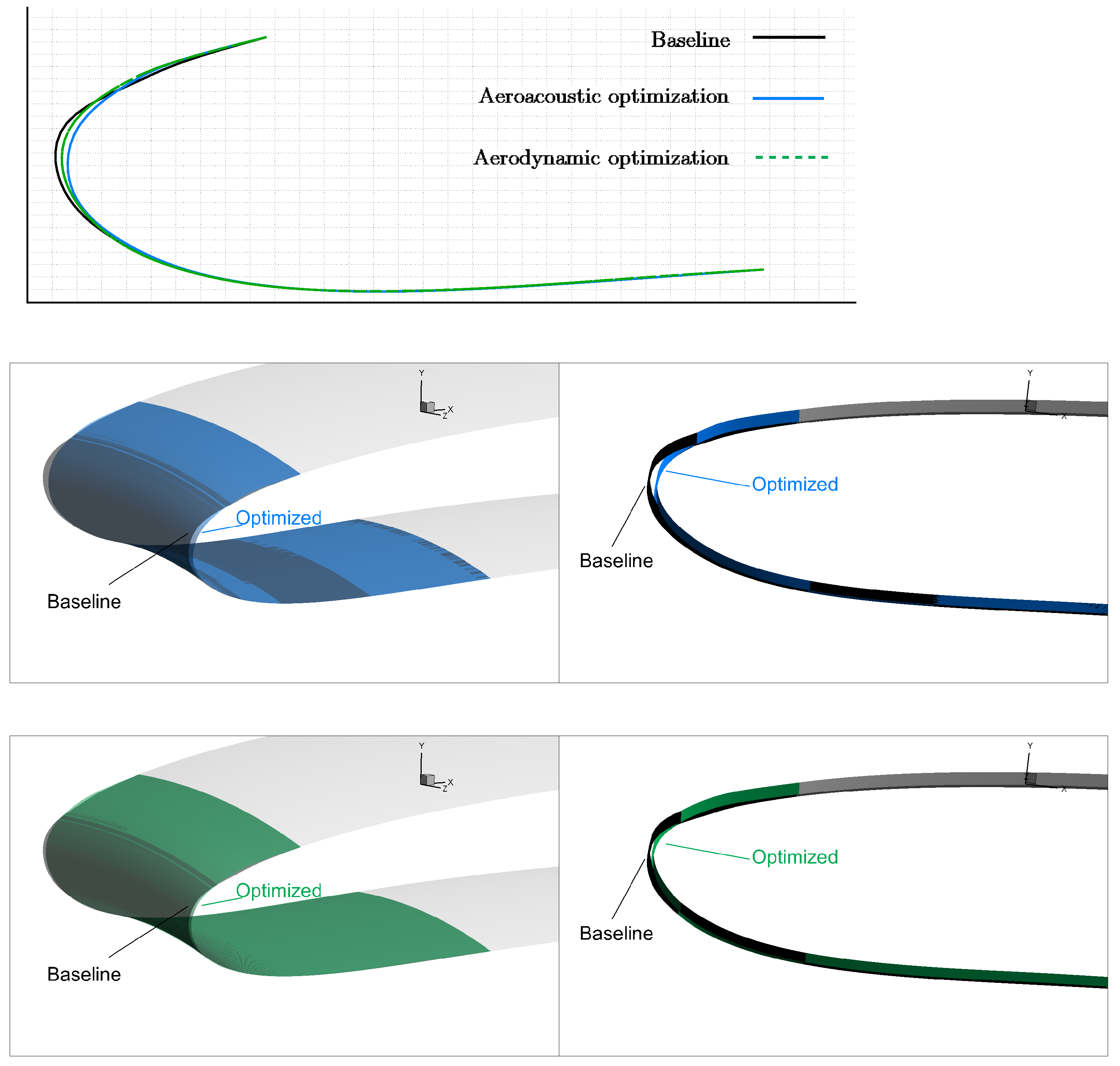
Figure 12 compares air intake generatrices and 3D views of the optimized and baseline geometries. As seen, in both optimization runs, the most noticeable change in shape occurs at the air intake lip which is pushed towards the fan inlet. The two optimization runs led to quite similar geometries; however, some small differences are enough to cause pronounced differences in aeroacoustic performance.

5. Conclusions

This paper presented a hybrid method (a RANS solver coupled with the FW–H analogy) to perform the aeroacoustic (and aerodynamic) shape optimization of a 3D aero-engine intake at an affordable computational cost. To do so, the analysis and continuous adjoint-based optimization tool of the in-house CFD solver PUMA, enhanced with the differentiation of the FW–H analogy, was used. The major working hypothesis was that the compressor geometry is fixed and so are the pressure conditions at the fan inlet. Due to the axisymmetric shape of the engine intake, the 3D flow and adjoint equations were solved in the rotating frame of reference in a domain corresponding to a single blade passage of the compressor fan, resulting in a significant reduction in memory footprint and solution time. The rotation of flow and adjoint fields to generate the corresponding unsteady fields required for computing the FW–H integral was needed. It was shown that the proposed method can provide aeroacoustic results that agree with those computed via pure CFD. Aeroacoustic and aerodynamic optimizations were performed separately, targeting minimum noise at the blade passing frequency or minimum total pressure losses, respectively. The results showed that, by incorporating more rows of receivers in the definition of the aeroacoustic objective function, the noise was successfully reduced in a wider range than with a single row of receivers. In both optimizations, the optimized geometries demonstrated enhanced aerodynamic and aeroacoustic performance compared with the baseline configuration. In addition, the aerodynamic optimization showed limited impact compared with the aeroacoustic optimization, likely due to the use of an already aerodynamically optimized geometry.

Author Contributions

Conceptualization, M.M. and K.G.; Methodology, M.M., K.G., X.T. and K.T.; Software, M.M., X.T., V.A. and K.T.; Formal Analysis, M.M., X.T. and V.A., Validation, M.M.; Writing—original draft preparation, M.M.; Writing—review and editing, M.M., V.A., X.T., K.T. and K.G.; Supervision, K.G. All authors have read and agreed on the published version of the manuscript.

Funding

This work was part of the MADELEINE project (2018–2021), which received funding from the European Union’s Horizon 2020 research and innovation programme under grant agreement No. 769025.

Data Availability Statement

The data are not publicly available due to confidentiality issues.

Acknowledgments

The authors thank Rolls-Royce plc. (S. Shahpar) and the research group of the Institute of Sound and Vibration Research (ISVR) of the University of Southampton (L. Wu) for providing the initial intake geometry and the boundary conditions of the fan inlet used herein.

Conflicts of Interest

The authors declare no conflict of interest.

References

  1. Thoma, E.; Grönstedt, T.; Zhao, X. Quantifying the environmental design trades for a state-of-the-art turbofan engine. Aerospace 2020, 7, 148. [Google Scholar] [CrossRef]
  2. Hansell, A.; Blangiardo, M.; Fortunato, L.; Floud, S.; de Hoogh, K.; Fecht, D.; Ghosh, R.; Laszlo, H.; Pearson, C.; Beale, L.; et al. Aircraft noise and cardiovascular disease near Heathrow airport in London: Small area study. BMJ 2013, 347. [Google Scholar] [CrossRef] [PubMed]
  3. Kallas, S.; Geoghegan-Quinn, M.; Darecki, M.; Edelstenne, C.; Enders, T.; Fernandez, E.; Hartman, P. Flightpath 2050 Europe’s vision for aviation. In Report of the High Level Group on Aviation Research, European Commission, Report No. EUR; European Commission: Brussels, Belgium, 2011; p. 98. [Google Scholar]
  4. Spalart, P.; Shur, M.; Strelets, M.; Travin, A. Initial noise predictions for rudimentary landing gear. J. Sound Vib. 2011, 330, 4180–4195. [Google Scholar] [CrossRef]
  5. Jawahar, H.; Ali, S.; Azarpeyvand, M.; da Silva, C. Aerodynamic and aeroacoustic performance of high-lift airfoil fitted with slat cove fillers. J. Sound Vib. 2020, 479, 115347. [Google Scholar] [CrossRef]
  6. Valldosera Martinez, R.; Afonso, F.; Lau, F. Aerodynamic shape optimisation of a camber morphing airfoil and noise estimation. Aerospace 2022, 9, 43. [Google Scholar] [CrossRef]
  7. Jameson, A. Aerodynamic design via control theory. J. Sci. Comput. 1988, 3, 233–260. [Google Scholar] [CrossRef]
  8. Wang, Q.; Moin, P.; Iaccarino, G. Minimal repetition dynamic checkpointing algorithm for unsteady adjoint calculation. Siam J. Sci. Comput. 2009, 31, 2549–2567. [Google Scholar] [CrossRef]
  9. Margetis, A.S.; Papoutsis-Kiachagias, E.; Giannakoglou, K. Lossy compression techniques supporting unsteady adjoint on 2D/3D unstructured grids. Comput. Methods Appl. Mech. Eng. 2021, 387, 114152. [Google Scholar] [CrossRef]
  10. Giles, M.B.; Pierce, N.A. An introduction to the adjoint approach to design. Flow Turbul. Combust. 2000, 65, 393–415. [Google Scholar] [CrossRef]
  11. Papadimitriou, D.; Giannakoglou, K. A continuous adjoint method with objective function derivatives based on boundary integrals for inviscid and viscous flows. Comput. Fluids 2007, 36, 325–341. [Google Scholar] [CrossRef]
  12. Papoutsis-Kiachagias, E.; Asouti, V.; Giannakoglou, K.; Gkagkas, K.; Shimokawa, S.; Itakura, E. Multi-Point aerodynamic shape optimization of cars based on continuous adjoint. Struct. Multidiscip. Optim. 2019, 59, 675–694. [Google Scholar] [CrossRef]
  13. Elham, A.; van Tooren, M.J. Discrete adjoint aerodynamic shape optimization using symbolic analysis with OpenFEMflow. Struct. Multidiscip. Optim. 2021, 63, 2531–2551. [Google Scholar] [CrossRef]
  14. Lozano, C.; Ponsin, J. Shock equations and jump conditions for the 2D adjoint Euler equations. Aerospace 2023, 10, 267. [Google Scholar] [CrossRef]
  15. Rumpfkeil, M.; Zingg, D. A hybrid algorithm for far-field noise minimization. Comput. Fluids 2010, 39, 1516–1528. [Google Scholar] [CrossRef]
  16. Zhou, B.; Albring, T.; Gauger, N.; Economon, T.; Palacios, F.; Alonso, J. A discrete adjoint framework for unsteady aerodynamic and aeroacoustic optimization. In Proceedings of the 16th AIAA/ISSMO Multidisciplinary Analysis and Optimization Conference, Dallas, TX, USA, 22–26 June 2015. AIAA 2015-3355. [Google Scholar]
  17. Zhou, B.; Albring, T.; Gauger, N.; Ilario, C.; Economon, T.; Alonso, J. A discrete adjoint approach for jet-flap interaction noise reduction. In Proceedings of the 58th AIAA/ASCE/AHS/ASC Structures, Structural Dynamics, and Materials Conference, Grapevine, TX, USA, 9–13 January 2017. AIAA 2017-0130. [Google Scholar]
  18. Fabiano, E.; Mavriplis, D. Adjoint-based aeroacoustic design-optimization of flexible rotors in forward flight. J. Am. Helicopter Soc. 2017, 62, 1–17. [Google Scholar] [CrossRef]
  19. Içke, R.; Baysal, O.; Lopes, L.; Zhou, B.; Diskin, B.; Moy, A. Toward adjoint-based aeroacoustic optimization for propeller and rotorcraft applications. In Proceedings of the AIAA Aviation 2020 Forum, Online, 15–19 June 2020. AIAA 2020-3140. [Google Scholar]
  20. Spagnoli, B.; Airiau, C. Adjoint analysis for noise control in a two-dimensional compressible mixing layer. Comput. Fluids 2008, 37, 475–486. [Google Scholar] [CrossRef]
  21. Freund, J. Adjoint-based optimization for understanding and suppressing jet noise. J. Sound Vib. 2011, 330, 4114–4122. [Google Scholar] [CrossRef]
  22. Kapellos, S.; Papoutsis-Kiachagias, E.; Giannakoglou, K.; Hartmann, M. The unsteady continuous adjoint method for minimizing flow-induced sound radiation. J. Comput. Phys. 2019, 392, 368–384. [Google Scholar] [CrossRef]
  23. Monfaredi, M.; Trompoukis, X.S.; Tsiakas, K.T.; Giannakoglou, K.C. An unsteady aerodynamic/aeroacoustic optimization framework using continuous adjoint. In Advances in Evolutionary and Deterministic Methods for Design, Optimization and Control in Engineering and Sciences; Springer: Berlin/Heidelberg, Germany, 2021; pp. 147–162. [Google Scholar]
  24. Monfaredi, M.; Trompoukis, X.; Tsiakas, K.; Giannakoglou, K. Unsteady continuous adjoint to URANS coupled with FW–H analogy for aeroacoustic shape optimization. Comput. Fluids 2021, 230, 105136. [Google Scholar] [CrossRef]
  25. Pan, F.; Coupland, J. An integrated optimization system for low noise nacelle design. In Proceedings of the 11th AIAA/CEAS Aeroacoustics Conference, Monterey, CA, USA, 23–25 May 2005; p. 2945. [Google Scholar]
  26. Cao, Y.; Stanescu, D. Shape optimization for noise radiation problems. Comput. Math. Appl. 2002, 44, 1527–1537. [Google Scholar] [CrossRef]
  27. Stanescu, D.; Mathelin, L.; Hussaini, Y. Optimal acoustic design of fan inlets for tone noise radiation. In Proceedings of the 9th AIAA/CEAS Aeroacoustics Conference and Exhibit, Hilton Head, SC, USA, 12–14 May 2003; p. 3269. [Google Scholar]
  28. Qiu, S.; Ying, J. A combined shape and liner optimization of a general aeroengine intake for tone noise reduction. Procedia Eng. 2015, 99, 5–20. [Google Scholar] [CrossRef]
  29. Qiu, S. A continuous adjoint-based aeroacoustic shape optimization for multi-mode duct acoustics. Proc. Inst. Mech. Eng. Part J. Mech. Eng. Sci. 2018, 232, 3897–3914. [Google Scholar] [CrossRef]
  30. Monfaredi, M.; Asouti, V.; Trompoukis, X.S.; Tsiakas, K.T.; Giannakoglou, K.C. Continuous adjoint-based aeroacoustic shape optimization of an aero-engine intake. In Proceedings of the 14th EUROGEN Conference, Athens, Greece, 28–30 June 2021. [Google Scholar]
  31. Luidens, R.W.; Stockman, N.O.; Diedrich, J.H. An Approach to Optimum Subsonic Inlet Design; ASME: New York, NY, USA, 1979; Volume 79672. [Google Scholar]
  32. Kazula, S.; Wöllner, M.; Höschler, K. Identification of efficient geometries for variable pitot inlets for supersonic transport. Aircr. Eng. Aerosp. Technol. 2020, 92, 981–992. [Google Scholar] [CrossRef]
  33. Vyas, U.; Braun, J.; Andreoli, V.; Paniagua, G. Short engine intakes: Design and trade-off aerodynamic recommendations. Aerosp. Sci. Technol. 2023, 134, 108164. [Google Scholar] [CrossRef]
  34. da Rocha-Schmidt, L.; Hermanutz, A.; Baier, H.; Seitz, A.; Bijewitz, J.; Isikveren, A.; Scarpa, F.; Allegri, G.; Remillat, C.; Feuilloley, E.; et al. Progress towards adaptive aircraft engine nacelles. In Proceedings of the 29th Congress of the International Council of the Aeronautical Sciences, St. Petersburg, Russia, 7–12 September 2014. [Google Scholar]
  35. Williams, J.; Hawkings, D. Sound generation by turbulence and surfaces in arbitrary motion. Philos. Trans. R. Soc. London. Ser. Math. Phys. Sci. 1969, 264, 321–342. [Google Scholar]
  36. Spalart, P.; Allmaras, S. A one-equation turbulence model for aerodynamic flows. Rech. Aerosp. 1994, 1, 5–21. [Google Scholar]
  37. Asouti, V.; Trompoukis, X.; Kampolis, I.; Giannakoglou, K. Unsteady CFD computations using vertex-centered finite volumes for unstructured grids on Graphics Processing Units. Int. J. Numer. Methods Fluids 2011, 67, 232–246. [Google Scholar] [CrossRef]
  38. Lockard, D. An efficient, two-dimensional implementation of the Ffowcs Williams and Hawkings equation. J. Sound Vib. 2000, 229, 897–911. [Google Scholar] [CrossRef]
  39. Papoutsis-Kiachagias, E.; Giannakoglou, K. Continuous adjoint methods for turbulent flows, applied to shape and topology optimization: Industrial applications. Arch. Comput. Methods Eng. 2016, 23, 255–299. [Google Scholar] [CrossRef]
  40. Trompoukis, X.; Tsiakas, K.; Asouti, V.; Kontou, M.; Giannakoglou, K. Optimization of an internally cooled turbine blade—mathematical development and application. Int. J. Turbomach. Propuls. Power 2021, 6, 20. [Google Scholar] [CrossRef]
  41. Tsiakas, K. Development of Shape Parameterization Techniques, a Flow Solver and Its Adjoint, for Optimization on GPUs. Turbomachinery and External Aerodynamics Applications. Ph.D. Thesis, NTUA, Athens, Greece, 2019. [Google Scholar]
  42. Luke, E.; Collins, E.; Blades, E. A fast mesh deformation method using explicit interpolation. J. Comput. Phys. 2012, 231, 586–601. [Google Scholar] [CrossRef]
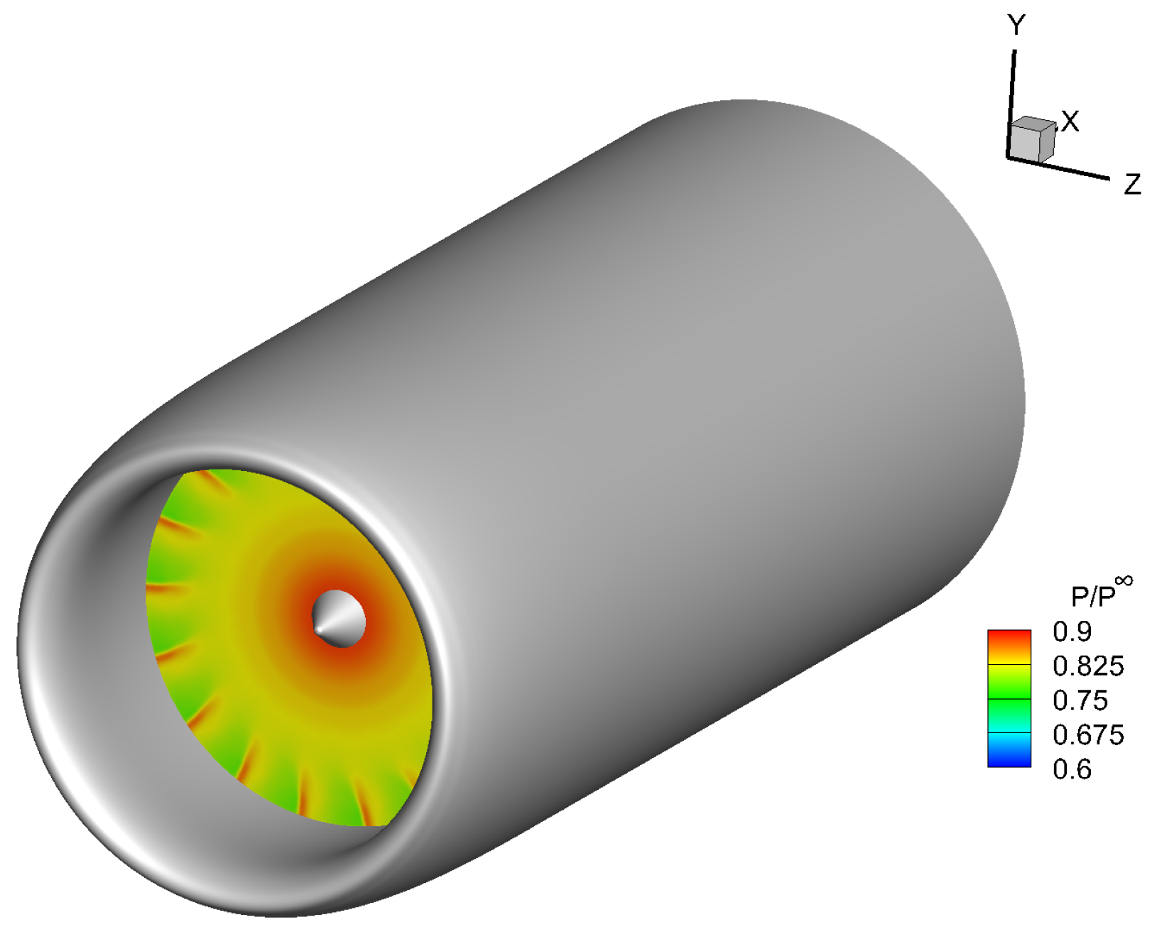
Figure 1. Perspective view of the aero-engine intake with a snapshot of the static pressure distribution, normalized via the far-field pressure, at the engine inlet.
Aerospace 10 00743 g001
Figure 2. A 2D sketch (not in scale) of the FW–H surface around an aero-engine. R is the fan inlet radius.
Aerospace 10 00743 g002
Figure 3. Workflow of a single aeroacoustic optimization cycle. Primal and adjoint are shown in green and blue, respectively.
Aerospace 10 00743 g003
Figure 4. (a) Entire and close–up views of the 3D CFD domain and the grid on one of the periodic boundaries. The parameterized part of the air intake is colored in red. (b) Isobar areas on the air intake, mid-plane and engine inlet.
Aerospace 10 00743 g004
Figure 5. (a) A close–up perspective view of the location of the FW–H surface, in blue, and three rows of receivers, used for code verification, within the CFD domain. Streamlines are colored based on pressure values. (b) A 2D view of the FW–H surface and receivers on the meridional plane. The locations of receivers on the meridional plane in terms of r and θ (distance from the center of the engine inlet area and angle w.r.t. the X axis, both defined in Figure 8) for receivers 1A, 2A and 3A are ( 2.05 R , 118 ) , ( 1.8 R , 98 ) and ( 1.6 R , 120 ) , respectively.
Aerospace 10 00743 g005
Figure 6. Comparison of the sound pressure within a period computed using the hybrid method and pure CFD at three different locations of receivers (a) 1A, (b) 2A and (c) 3A.
Aerospace 10 00743 g006
Figure 7. Distribution of the NURBS control points for the parameterization of the air intake generatrix. The first and last control points (in black) are fixed during the optimization.
Aerospace 10 00743 g007
Figure 8. Schematic of the receivers’ locations (on a meridional plane) used in the definition of the aeroacoustic objective function (intake shape and receiver locations are not in scale). The three rows of receivers are located at the same distance of r from the center of the engine inlet area, with R being the fan inlet radius. Angle θ is measured on the meridional plane w.r.t. the X axis.
Aerospace 10 00743 g008
Figure 9. Aeroacoustic optimization results. (a) Convergence history of J a c , normalized via its initial value. (bd) Comparisons of the time–series of pressure fluctuations, within a period, at receivers located at each of the three circumferential row locations.
Aerospace 10 00743 g009
Figure 10. Aeroacoustic optimization results. Comparison of the directivity plot of the SPL normalized via the initial SPL value at θ = 90 at the BPF, for receivers located at r = 8.8 R . Angle θ is defined in Figure 8.
Aerospace 10 00743 g010
Figure 11. Results after 12 aerodynamic optimization cycles. (a) Convergence of the total pressure at fan inlet, normalized via its initial value. (b) Comparison of the results from the aerodynamic and aeroacoustic optimizations.
Aerospace 10 00743 g011
Figure 12. Comparison of the generatrices of the baseline and two optimized geometries of the parameterized part of the air intake (top). The baseline along with the aeroacoustically (middle), and aerodynamically (bottom) optimized geometries.
Aerospace 10 00743 g012
Disclaimer/Publisher’s Note: The statements, opinions and data contained in all publications are solely those of the individual author(s) and contributor(s) and not of MDPI and/or the editor(s). MDPI and/or the editor(s) disclaim responsibility for any injury to people or property resulting from any ideas, methods, instructions or products referred to in the content.