Article

Dynamic Analysis of a Large Deployable Space Truss Structure Considering Semi-Rigid Joints

School of Astronautics, Harbin Institute of Technology, Harbin 150001, China
*
Author to whom correspondence should be addressed.
Aerospace 2023, 10(9), 821; https://doi.org/10.3390/aerospace10090821
Submission received: 27 August 2023 / Revised: 13 September 2023 / Accepted: 18 September 2023 / Published: 21 September 2023

Abstract

:
Joints are widely used in large deployable structures but show semi-rigidity due to performance degradation and some nonlinear factors affecting the structure’s dynamic characteristics. This paper investigates the influence of semi-rigid joints on the characteristics of deployable structures in orbit. A virtual connection element of three DOFs is proposed to model the semi-rigid joints. The governing equations of semi-rigid joints are established and integrated into the dynamic equation of the structures. A series of numerical experiments are carried out to validate the proposed model’s accuracy and efficiency, and the deployable truss structures’ static and dynamic responses are analyzed. The results show that semi-rigid joints exacerbate the effects of an in-orbit microvibration on the stability of deployable truss structures. Semi-rigid joints lower the dominant frequencies of structures, leading to a ‘closely-spaced-frequencies’ phenomenon and altering the dynamic responses significantly. The effects of semi-rigid joints on deployable truss structures are long-term and can be used to establish a relationship model between structural performance and service life. Nonlinear effects vary with the external load and depend on the structures’ instantaneous status. These results indicate that semi-rigid joints significantly influence the characteristics of deployable structures, which must be considered in the design and analysis of high-precision in-orbit deployable structures.

1. Introduction

Spacecraft structures tend to be large-scale, flexible, and lightweight with the development of aerospace technology. Large deployable space structures can transform from a folded configuration to a deployed configuration to satisfy the requirements of applications [1,2]. Numerous works have been dedicated to this kind of structure’s dynamic modeling and nonlinear analysis [3,4,5,6,7]. Almost all tackle the joints in trusses as ideally rigid or hinged. However, due to performance degradation and some nonlinear factors, such as clearance, friction, and other factors, joints virtually are not ideal, and they are one of the major sources of structural nonlinearity and damping, which affect the dynamic response, stability, and pointing accuracy of structures in orbit [8,9]. The semi-rigidity of joints is the most typical of many unideal cases that affect the structure’s dynamic characteristics. Therefore, it must be considered in modeling space truss structures to improve model fidelity.
During the past few decades, the influence of semi-rigid joints on the performance of frame structures has been widely studied using the finite element method. Mohammed and Ismael [10] studied the influence of connection stiffness on the post-buckling behavior of frame structures, finding that the effect of joint stiffness on structural stability could be effectively reduced by adding an oblique structure to the frame structure. Keulen and Nethercot [11] assessed the nonlinear stiffness of joints and used the rotating spring element to simulate the joint structure in the frame. The research showed that the proposed method was suitable for the multi-story regular frame structure, which can be used to solve common geometric nonlinear problems. In Refs. [12,13], a nonlinear analysis of frame structures with rigid connections, semi-rigid connections, and hinge connections was carried out, proving the importance of connection stiffness to determine the overall stability and ultimate strength response of frame structures. A weak form of the incremental governing equation in the complementary energy approach was proposed in Ref. [14], which could effectively and accurately deal with flexible connected spatial structures’ static and dynamic problems. Kawashima et al. [15] and Chan [16] employed the direct stiffness method to analyze the vibration of frame structures and considered the influence of connection stiffness and friction. Chui et al. [17] proposed a geometric nonlinear analysis method for flexible connected frame structures with hysteretic connection characteristics based on the traditional static matrix analysis method, which can be applied to the deflection analysis of frame structures with nonlinear connection stiffness to obtain nonlinear dynamic response under dynamic loads. An original extension of the classic deformation method for global elastic analysis of steel construction with semi-rigid connections was developed in Ref. [18].
However, the aforementioned works mostly focused on rigid frame structures on the ground, and scant research has been dedicated to structures in orbit. Space truss structures are located in a different space environment from ground structures and require long-term service and unmanned operation. Therefore, there is a high demand for their working performance, such as pointing accuracy. The impact of micro-vibrations and other disturbances on the structure may be minimal, but it needs to be taken seriously. Furthermore, widespread semi-rigid joints inevitably affect the nonlinear dynamic characteristics of structures, and the large-scale effect of truss structures further aggravates this effect. Thus, the nonlinear dynamic response of such a structure needs to be focused on.
Furthermore, strong geometric nonlinearities lead to many difficulties in modeling and solving problems with the traditional finite element method, particularly for a truss structure with semi-rigid connections undergoing large deflection [19,20], in which semi-rigid joints involve complex constraints. Moreover, large-scale structures further complicate the modeling. Therefore, a unified modeling principle is urgently needed to reduce the difficulty of modeling and improve analysis efficiency. The Finite Particle Dynamic Method (FPDM) is a novel structural analysis method based on the Vector Form Intrinsic Finite Element (VFIFE) proposed by E. C. Ting et al. [21,22,23] in 2004. In FPDM, the structure’s shape is described by the particles’ position, and the particles’ behavior follows Newton’s law. The resultant force of the particle is calculated by using the principle of virtual work to establish the particle motion governing equation. A large body of research shows that FPDM possesses good convergence for large deformation [24], large displacement [25], and fracture failure [26,27,28] problems due to the explicit integral method. However, there is little work on nonlinear dynamic analysis of deployable truss structures with semi-rigid joints using FPDM.
The main goal of this paper is to investigate the influence of semi-rigid joints on the nonlinear dynamic response and dynamic characteristics of deployable truss structures using a unified modeling principle. The remainder of this paper is organized as follows. The properties of semi-rigid joints and their possible influences on the dynamics of deployable truss structures are briefly introduced in Section 2. A virtual connection element is innovatively proposed to model the behavior of the semi-rigid joints in Section 3. The formulation of the additional joint moment, the governing equation of the moment of the particle at the joint node, and the dynamic equation of the whole truss structure are also presented in this section. Section 4 validates the proposed method first and then investigates the effects of the semi-rigid joints on the structure’s dynamic characteristics through a series of numerical examples. Concluding remarks and directions for future research are discussed in Section 5.

2. Problem Description

Hinge joints are the most intuitive and are often used for mobile joints without rotational constraints. Most frame structures can be considered rigid joints when welding, riveting, multi-point bolt fastening, and using similar connection methods. Generally, a joint containing a coil spring can be regarded as a semi-rigid joint. Some rigid joints need to be treated as semi-rigid when considering assembly clearance and performance degradation due to fatigue.
Figure 1a,b illustrate a typical large deployable structure composed of beams and joints that can unfold up to 10 m or longer. Often possessing large flexibility and low natural frequencies, this structure is subjected to various loads but requires high precision and structural stability. It can be fully folded to minimize its storage space during the launch. Driven by deployment mechanisms in the joints, the structure self-unfolds after entering the working state and then locks the joints. Figure 1c shows the deformation of a deployable truss structure under external loads. Relative rotations exist between adjacent beams at the joint due to the semi-rigid connection. These beam pairs are constrained to some extent but not rigidly, as shown in Figure 1d. Semi-rigid joints affect the transfer of internal force and moment between adjacent beams. So, the stiffness, as well as the dynamic response, will be affected. Moreover, these effects may be amplified with the increase in structure size.
The joint structure and material properties determine semi-rigidity characteristics. Experiments can measure semi-rigidity characteristics and describe them using M * γ * curves [29], as shown in Figure 1e. The rotating stiffness S r caused by semi-rigid joints can be expressed as
S r = d M * d γ *
where M * is the moment at the joint and γ * is the relative angle at the joint, i.e.,
γ * = γ 1 γ 2
where γ 1 and γ 2 denote the rotation angles of the adjacent beams connected at the joint, as shown in Figure 1d. The rotational stiffness S r varies with materials, and structures and can be linear and nonlinear. The main goal of this paper is to investigate the influence of various kinds of rotating stiffness S r on the dynamic behavior of deployable trusses.

3. Model Establishment of Truss Structure

In the traditional analysis of a truss structure, joints between beams and bars are usually regarded as rigid connections, which are usually treated as a common node in the finite element method. However, this method does not apply to semi-rigid joints, which must be simulated with additional complex constraints. In this section, a unified modeling method for semi-rigid joints is proposed to improve modeling accuracy and efficiency.

3.1. Connection Element of Semi-Rigid Joints

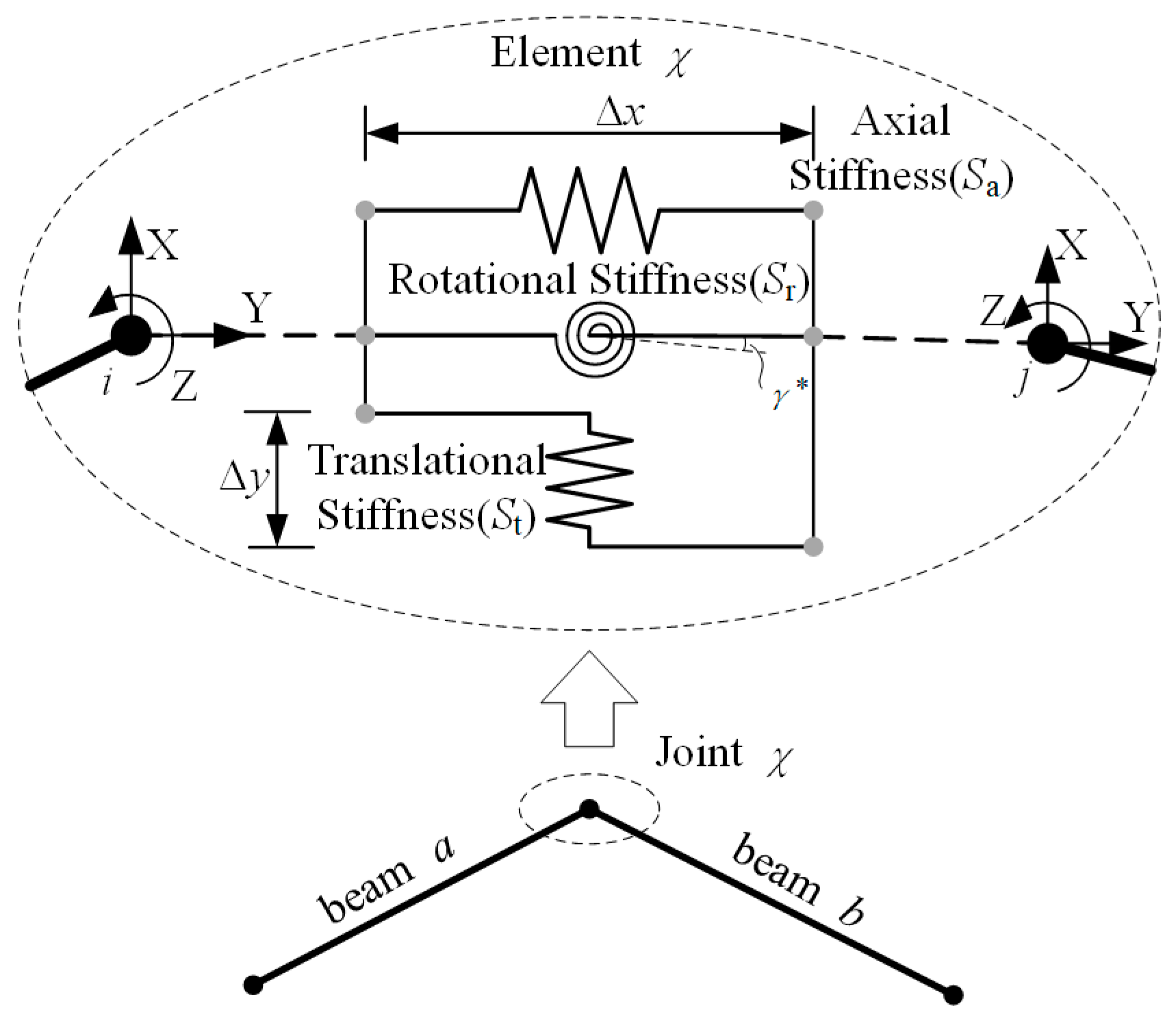
Consider the semi-rigid joint χ connecting two beams a and b, as shown in Figure 2. This joint can be modeled as a virtual spring system of three degrees of freedom (3 DOFs), having no mass and length. This spring system connects the nodes i and j, i.e., the ends of the two adjacent beams.
The constraint force and moment of the joint on the two beams are decomposed into three components along the 3 DOFs. They are given by
F i * = S a Δ x S t Δ y T ,   M i * = S r γ *
where
Δ x Δ y T = x i x j y i y j T
where x i , y i and x j , y j are the coordinates of the nodes i and j. S a and S t denote the virtual joint’s axial and translational stiffness, respectively. The force and moment act on node j are F j * = F i * and M j * = M i * , respectively.

3.2. VFIFE Model for Beams

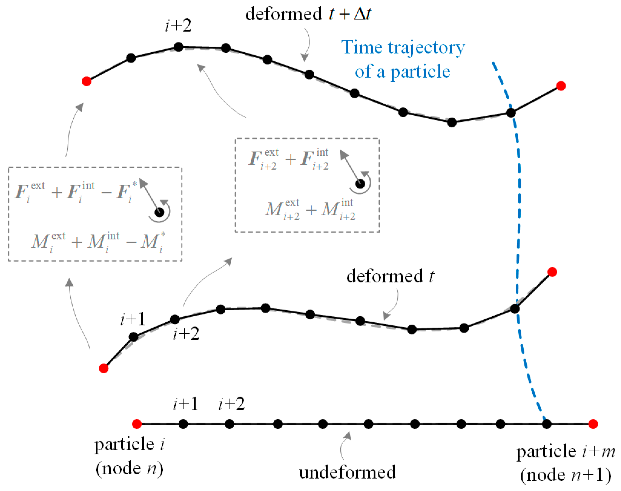
According to the VFIFE method, a beam, although a physical continuum structure, can be described by finite points connected by massless elements, as shown in Figure 3. These points have mass and moment of inertia, thus also called particles, defined as [25]
m i = m i c + k = 1 n m ^ k ,   m ^ k = 1 2 ρ A l
I i = I i c + k = 1 n I ^ k ,   I ^ k = 1 2 m ^ k r 2
where n is the number of beam elements connected to particle i. For particles not located at the ends of beams, n = 2. For particles at the ends of beams, also called nodes, n depends on how many beams are connected at the joint. m i c is the mass of objects at the position of the particle i. For nodes, i.e., particles connected by joints, m i c should include masses of the joints. ρ is the material density of the beam, A denotes the cross-sectional area, and l is the length of the beam element. The equivalent mass m ^ k represents the mass effect of beam elements, divided equally by the particles at the ends. Similarly, the moment of inertia of particle i arises from the beam elements connected to it. Every contribution I ^ k is determined by the equivalent mass m ^ k and the gyration radius r of the cross-section in the direction of the principal coordinates.
All internal and external forces are added to the particles, as shown in Figure 3. Particles at the ends of beams, i.e., nodes, are also subjected to constraint forces and moments of joints,
F i = F i ext + F i int F i * , M i = M i ext + M i int M i * , for   particles   at   joints
F i = F i ext + F i int , M i = M i ext + M i int , for   ordinary   particles  
The formulas of F i * and M i * are given in Equation (3). The formulas for internal forces F i int and moments M i int are computed according to the VFIFE method. Both of them are caused by pure deformation.
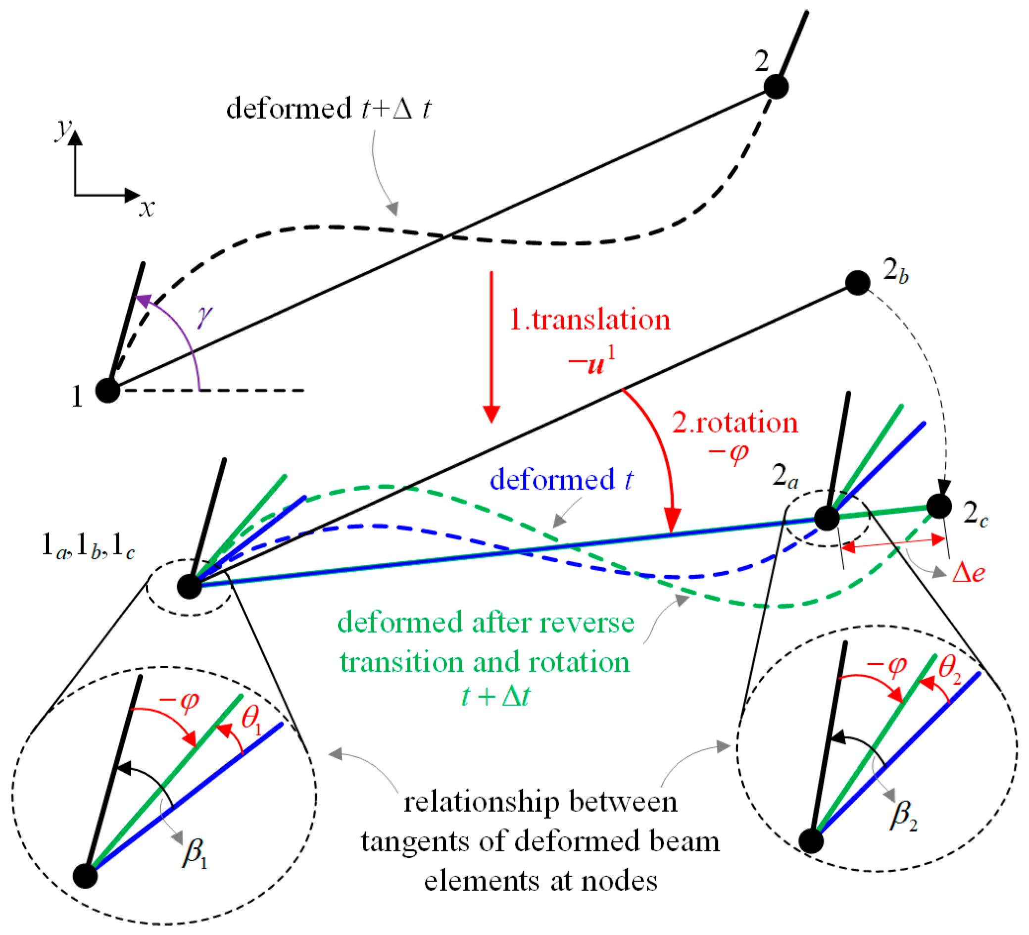
VFIFE innovatively proposes an approach to extract pure deformation by applying reverse motion to the structure. As shown in Figure 4, taking node 1 as the reference point, the virtual reverse translation of u 1 and the virtual reverse rotation φ are applied to elements 1–2.
As a result, the pure deformation of elements 1–2 is revealed, composed of three components: axial length increment, deformation angle of node 1, and deformation angle of node 2. They are given by
Δ e = l l a ,   θ 1 = β 1 + φ ,   θ 2 = β 2 + φ
where l and l a are the lengths of the element at time t + Δ t and t, respectively. β 1 and β 2 are rotating angles of nodes 1 and 2, respectively, from time t to t + Δ t . Each of them is composed of two parts; one is caused by pure deformation θ i , and the other one is caused by rigid rotation φ . It should be pointed out that these angles are the same in local and global coordinates due to their common z-axis, and γ ( t ) is the rotating angle of the nodes, which varies with time.
After obtaining the pure deformation increment from time t to t + Δ t , the increments of forces and moments at the beam element can be calculated by
Δ F ^ 1 x = E a A a l a Δ e ,   Δ F ^ 2 x = E a A a l a Δ e
Δ F ^ 1 y = Δ M 1 z + Δ M 2 z l a ,   Δ F ^ 2 y = Δ M 1 z + Δ M 2 z l a
Δ M 1 z = E a I a l a 4 θ 1 + 2 θ 2 ,   Δ M 2 z = E a I a l a 2 θ 1 + 4 θ 2
where Δ F ^ i x and Δ F ^ i y denote internal force increment on particle i from time t to t + Δ t . Δ M i z represents the internal moment increment. The subscript indicates the values in the local coordinate system. The internal force acting on particle i at time t + Δ t can be expressed as
F ^ i int t + Δ t = F ^ i int t + Δ F ^ i x Δ F ^ i y T M i int t + Δ t = M i int t + Δ M i z
Appling coordinate transform, the internal force in the global coordinate system is obtained using the following equation:
F i int = R 2 × 2 F ^ i int
where R 2 × 2 is the directional cosine matrix from the local coordinate system to the global coordinate system.
m i m i I i d 2 d t 2 x i y i γ i = F i x F i y M i
where F i x F i y = F i . Solving Equation (15), the dynamic response of the truss structure connected by semi-rigid joints can be obtained.

3.3. Solution Procedure

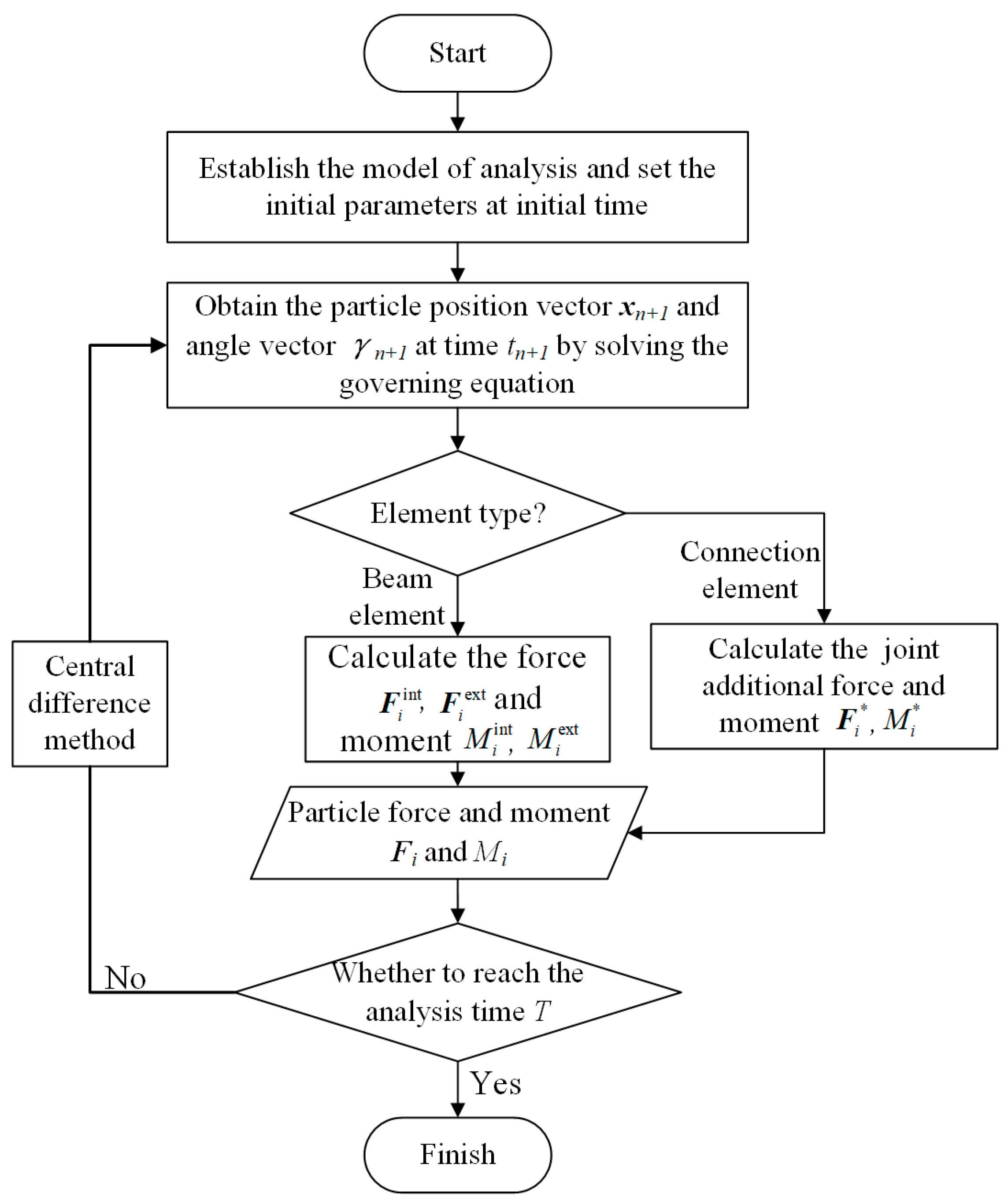
Figure 5 shows the logical diagram of modeling and solving procedures using FPDM. The displacement of step n + 1 depends on the previous two steps n and n 1 . The unified modeling method integrates the elements of the joints and beams to construct the truss structure numerical analysis model.
The central difference method is chosen to solve the governing equation, which remains simple and efficient despite the increase in model scale. The formula for particle displacement and the rotation angle is then given by
x i n + 1 = C 1 h 2 m i F i + 2 C 1 x i n C 2 x i n 1 γ i n + 1 = C 1 h 2 I i M i + 2 C 1 γ i n C 2 γ i n 1
where
C 1 = 1 1 + ζ h 2 , C 2 = C 1 1 1 ζ h 2
The dynamic response of the structure is obtained by FPDM. To obtain the static solution, it is necessary to introduce the energy dissipation mechanism into the governing equation, so a virtual damping force is added here. ζ denotes the virtual damping coefficient, which leads to a stable status.

4. Results and Discussion

4.1. Method Validation

To validate the accuracy and efficiency of the proposed model, a series of classical nonlinear problems are studied numerically, including geometric nonlinearity, snap-through buckling, and nonlinear dynamic response. The results are compared with those in the literature.

4.1.1. Geometrically Nonlinear Analysis of Column with Semi-Rigid Connection

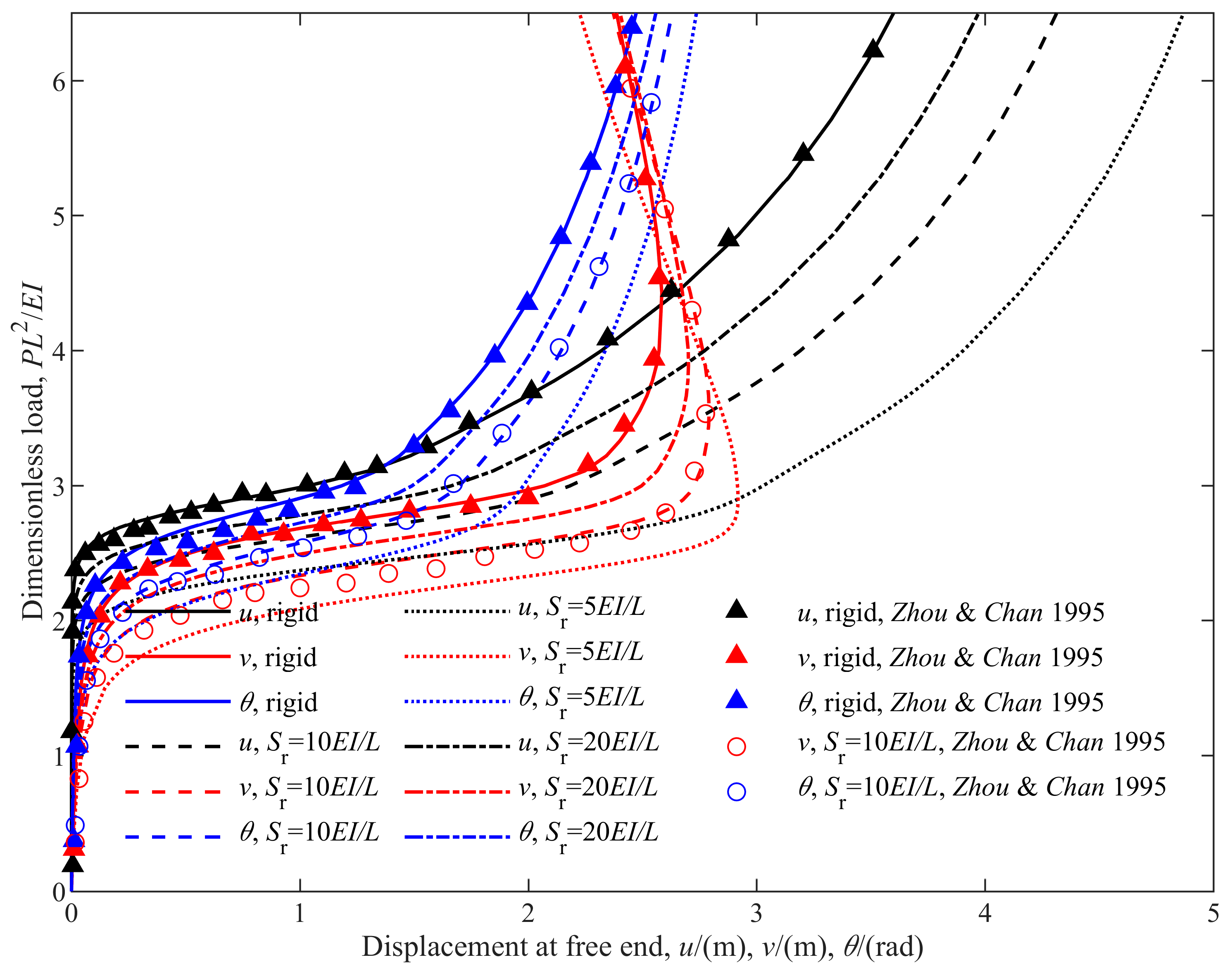
First, a column constrained by a semi-rigid joint and subjected to lateral and longitudinal loads is investigated—a classical benchmark problem to verify the validity of numerical methods for nonlinear geometric problems. Structural and material parameters in Ref. [30] are adopted directly for the sake of comparison. Various types of joints are considered, including rigid and semi-rigid ones. Figure 6 shows the results obtained by using the FPDM, which are depicted by solid and dashed lines.
As shown in Figure 6, points marked by upward-pointing triangles and circles are generated from data in the literature. It can be found that the results agree with those in the literature very well. Thus, it can be concluded that the proposed model is applied to nonlinear geometric problems. Moreover, another two cases, where S r equals 5   E I / L and 20   E I / L , are investigated, respectively. Comparing the deformation curves with different joint stiffness, i.e., the red lines, it can be found that the column switches from stable to unstable as the load increases. The joint stiffness has a significant influence on the critical load.

4.1.2. Snap-through Analysis of William’s Toggle Frame

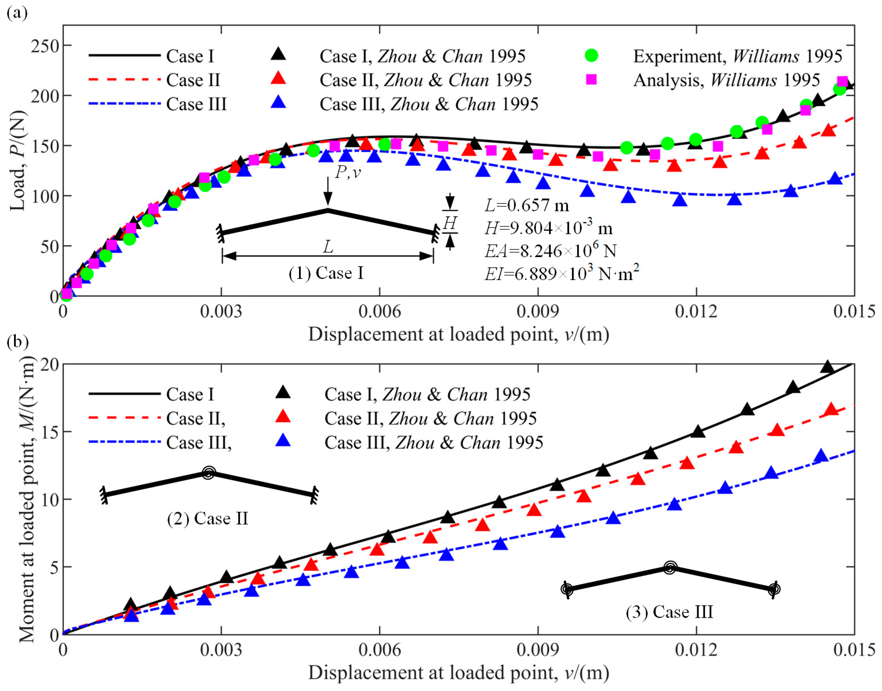
Figure 7 shows William’s toggle frame, which exhibits strong nonlinear behavior when subjected to a vertical load, named snap-through buckling. This example aims to prove the validity of the proposed model for large deflection problems. A structure and parameters identical to Refs. [12,13,30,31] are employed and illustrated in Figure 7. The results include the load–displacement curve and bending moment–displacement curve at the loaded point, respectively, in Figure 7a,b. Three cases are considered. In the first case, all joints are rigid. A semi-rigid joint is located at the vertex in the second case, and all joints are semi-rigid in the last one. All semi-rigid joints have a rotating stiffness S r = 10   E I / L .
Excellent agreements between the results obtained by using the proposed model and those in the literature [30,31] are observed. Snap-through buckling behavior under vertical load is captured precisely, as shown in Figure 7a. Thus, these results demonstrate the validity of the FPDM model for large deflection problems. Moreover, the results also reveal that the semi-rigid joints make the critical load of the structure decline significantly, which impairs the capacity of the structure to keep high structural precision and stability under disturbance.

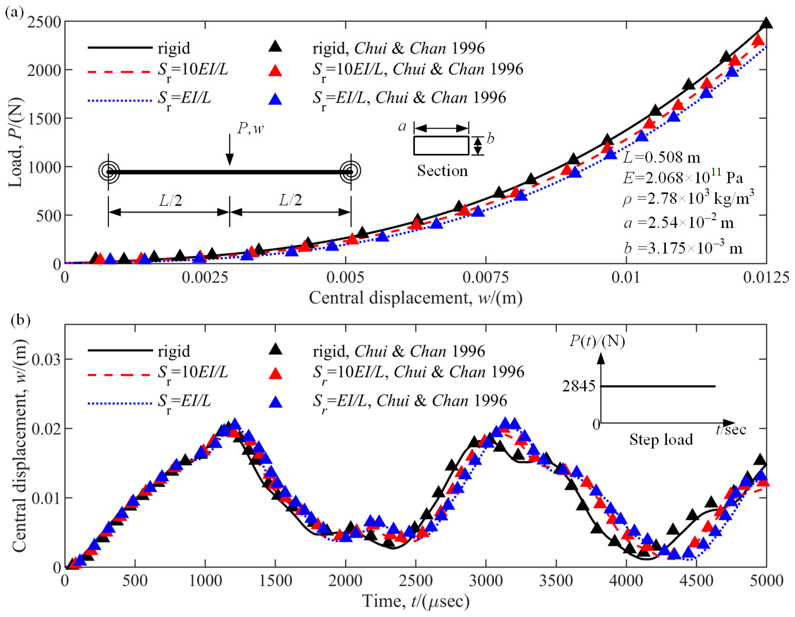
4.1.3. Static and Dynamic Response of a Clamped-Clamped Beam

A beam constrained by semi-rigid joints at its ends and subjected to a concentrated load at the midpoint is investigated in this section. Material and structural parameters are illustrated in Figure 8, the same as in Ref. [17]. The rotating stiffness S r is 10   E I / L and E I / L . The beam’s static and dynamic responses with various joint stiffness are computed using the FPDM and depicted in Figure 8a,b using solid and dashed lines. The results are compared with those in Ref. [17], depicted by upward-pointing triangles. As expected, they coincide very well regardless of the specific joint stiffness. For the static problem, the stiffening phenomenon of the beam is revealed accurately. For the dynamic problem, the nonlinear response of the beam subjected to a step load of magnitude 640lb (2845 N) is studied in detail. It can be observed that the displacement–time curves obtained using the FPDM match with those in the literature very well. Moreover, it can be found that the decrease in joint stiffness results in an apparent decrease in natural frequencies.
Conclusions can be drawn from the aforementioned numerical experiments that the FPDM is valid and precise for nonlinear static and dynamic problems. It should be pointed out that the above examples also demonstrate the vital influence of semi-rigid joints on static and dynamic characteristics and responses. This phenomenon will be investigated deeply in the next section.

4.2. Influence of Semi-Rigid Joints on Dynamics of Deployable Structures

Now, we investigate semi-rigid joints’ influence on the static and dynamic behavior of the large deployable space truss structure, as shown in Figure 1a. This truss structure is 10 m long after deployment and comprises 30 beams connected by rigid and semi-rigid joints. The beams are made of aluminum alloy. Table 1 tabulates the geometric and material parameters of the structure. Three kinds of joints are considered, including ideal rigid joints and semi-rigid joints of rotating stiffness 100   E I / L and 10   E I / L .

4.2.1. Effects of Linear Joint Stiffness

Three numerical experiments are carried out to investigate the effects of the joint stiffness on the bending stiffness, dominant frequencies, and dynamic responses of the truss structure.
  • Case 1: Effects on structural bending stiffness
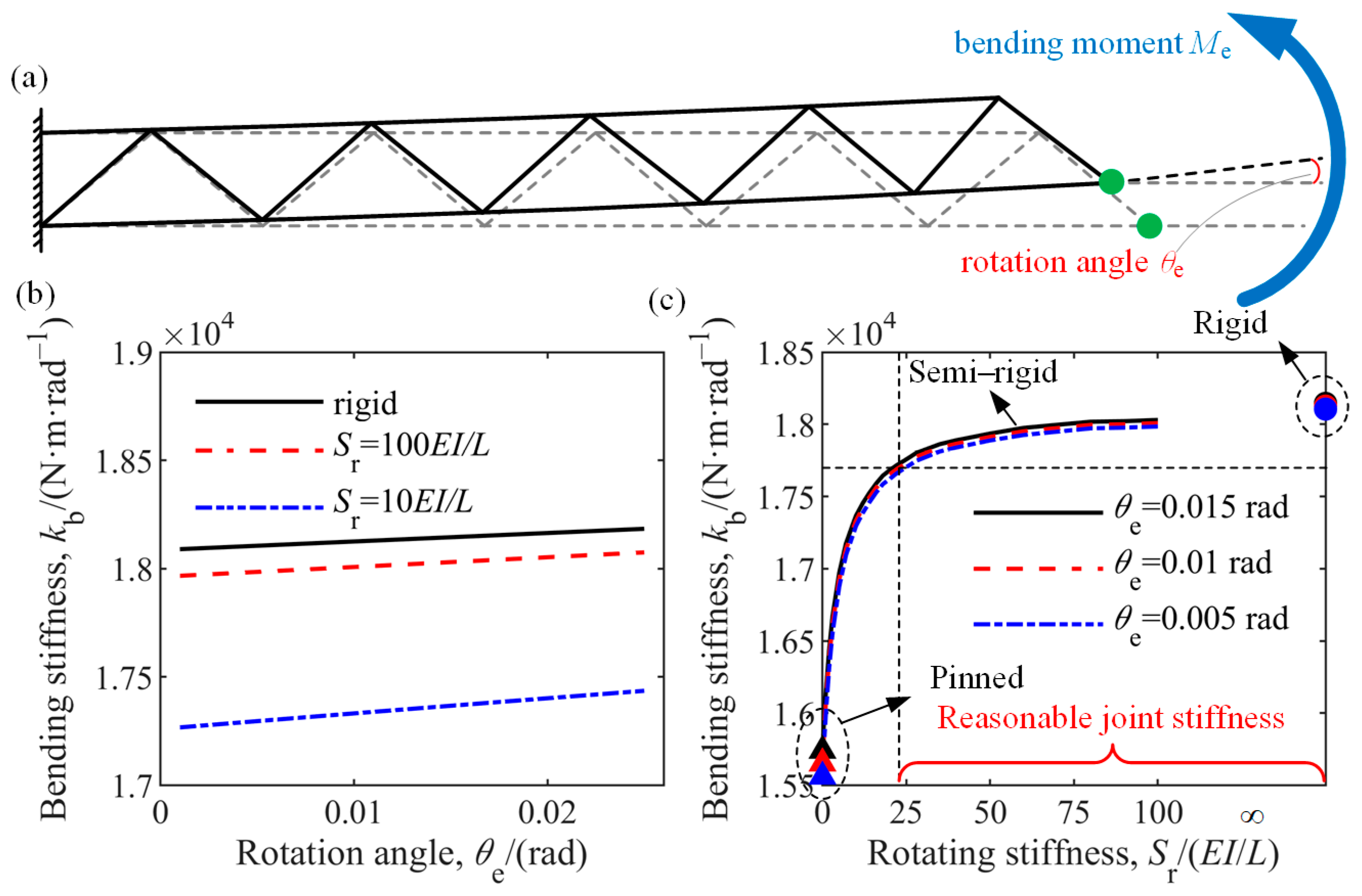
First, consider the quasi-static bending of the truss. A gradually increasing moment M e is enforced at the end of the truss. The quasi-static bending stiffness k b = M e / θ e at every rotation angle is calculated and depicted in Figure 9. It can be found that the decrease in joint stiffness results in an apparent decrease in bending stiffness. The bending stiffness is lower about 0.6% when S r = 100   E I / L , compared to the case where all joints are rigid. It is also observed that as the rotation angle increases, the truss’s stiffness also increases, as shown in Figure 9b. The relationship between the stiffness of the whole truss and the rotating stiffness of the joints is illustrated in Figure 9c. The stiffness of the truss with semi-rigid joints is between that of the rigid-connected truss and the pinned-connected truss. The increase in the rotating stiffness of the joints results in the rise of the stiffness of the whole truss in a step-likewise form, as shown in Figure 9c. When S r varies from 0 to 25   E I / L , a surge in the stiffness of the truss is observed. Further, the increase in S r has a smaller and smaller influence, and the bending stiffness of the truss ultimately approaches the value of the rigid-connected truss.
Large space structures usually work in orbit for more than ten years, and structural fatigue and joint degradation occur inevitably. The stiffness of joints decreases over time. Correspondingly, the stability of the structure will also be affected, which affects the pointing accuracy of the in-orbit truss structure. The trend in Figure 9c indicates that the stiffness of joints must be kept within a reasonable range and bigger than a critical value as shown in the figure. This is very important when monitoring and evaluating the performance of large structures.
2.
Case 2: Effects on natural frequencies
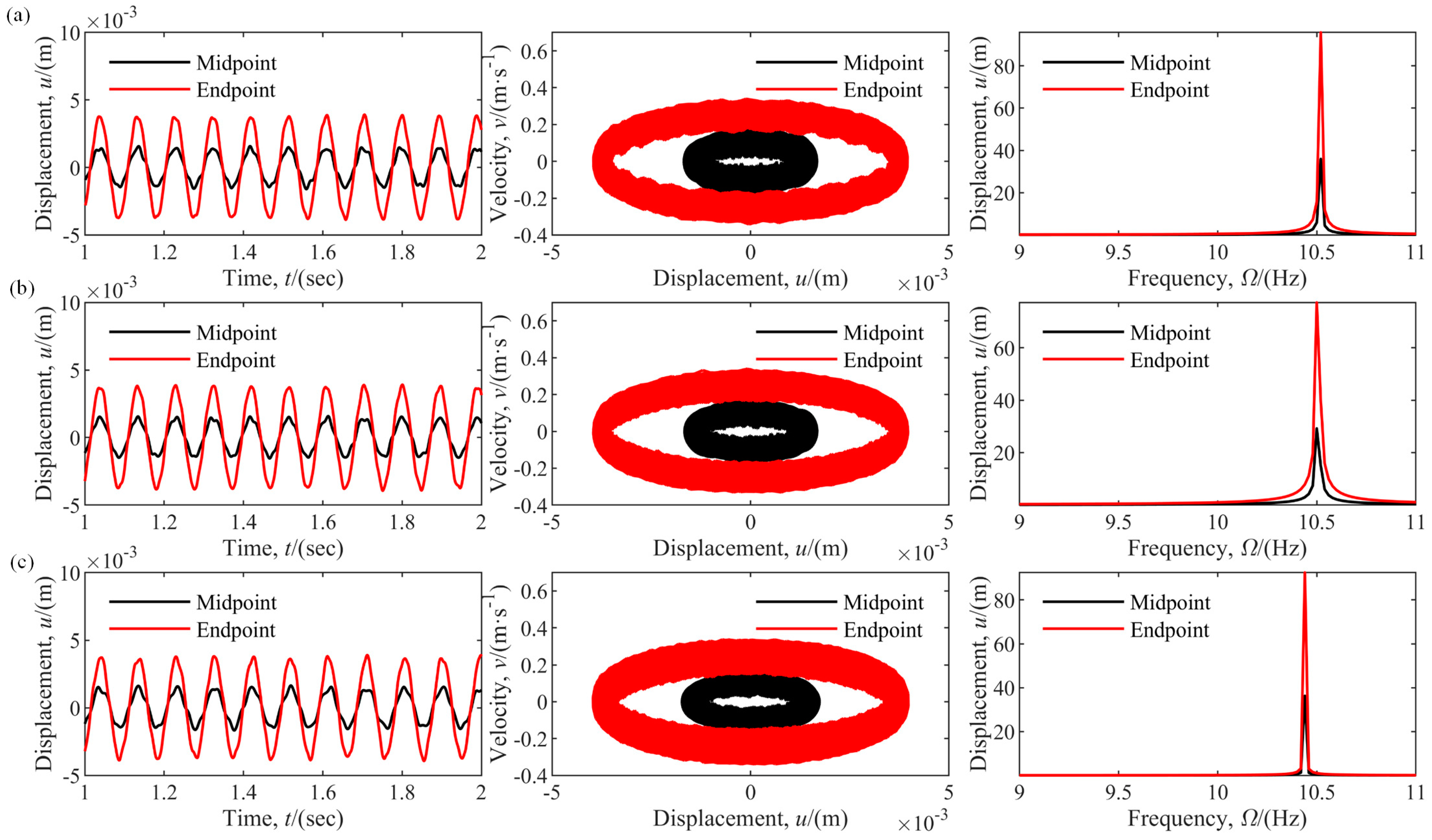
Consider the free vibration of a truss having an initial displacement of 0.05 m and no damping. Dynamic responses of the same truss with different joint stiffnesses are plotted in Figure 10, including the displacements, velocities, and frequency spectrum at the midpoint and endpoint. The dominant frequencies are obtained through fast Fourier transform. The values are 10.50 Hz and 10.44 Hz when the rotating stiffness is 100   E I / L and 10   E I / L , 0.19% and 0.8% lower than the rigid truss, respectively.
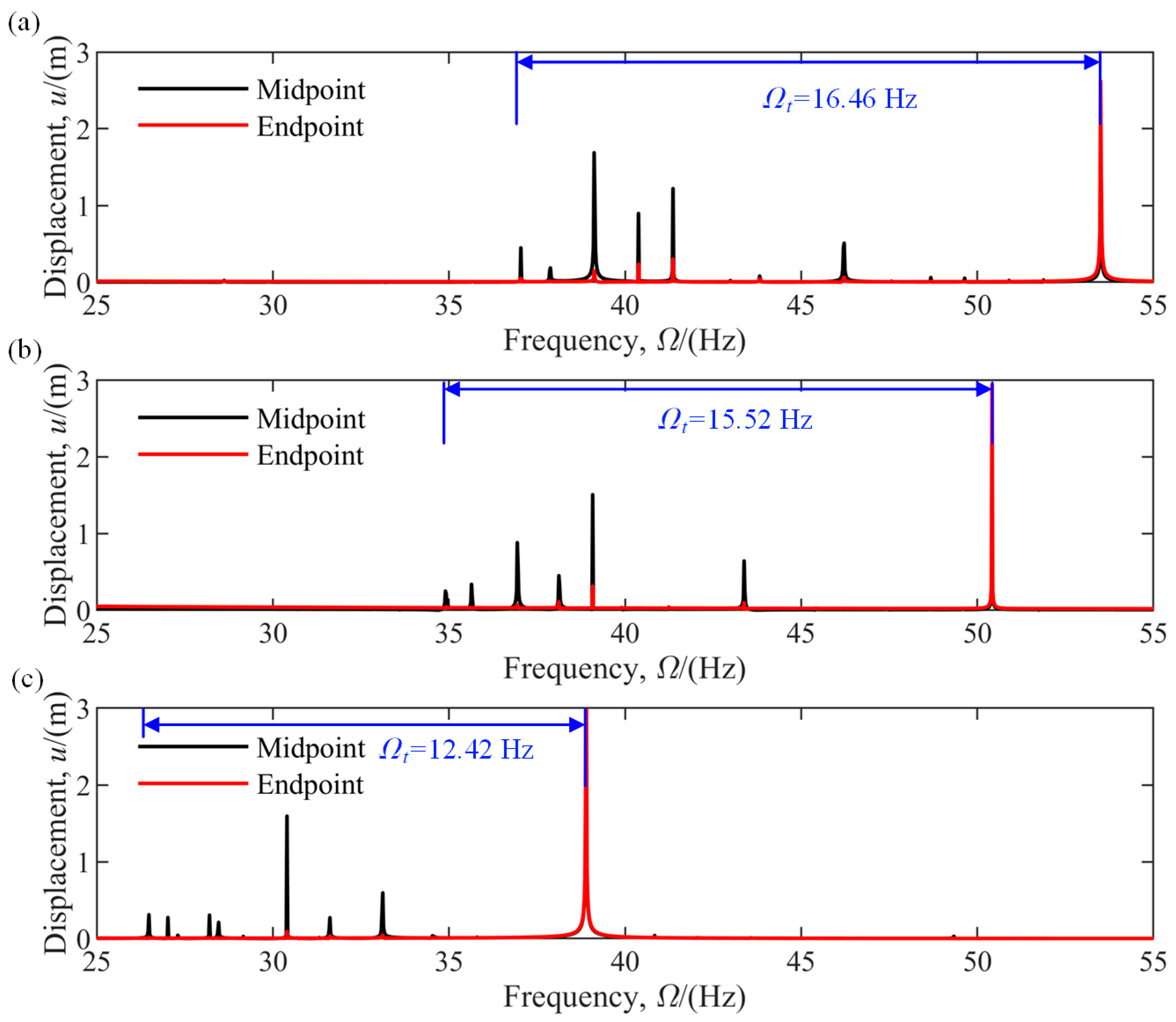
As shown in Figure 11, the semi-rigid joints lower the dominant frequencies, resulting in a ‘closely spaced frequencies’ phenomenon. The blue lines in the figure illustrate the span of the dominated frequencies, whose interval shrinkages from 16.46 Hz to 12.42 Hz. A significant deviation of frequencies is observed compared to the rigid-connected structure. If the structure is regarded as ideally connected, the prediction of high–order frequencies probably deviates by as much as 25~50%. It demonstrates that the effect of semi-rigid joints cannot be ignored for precise space structures in the design process.
3.
Case 3: Effects on the dynamic response
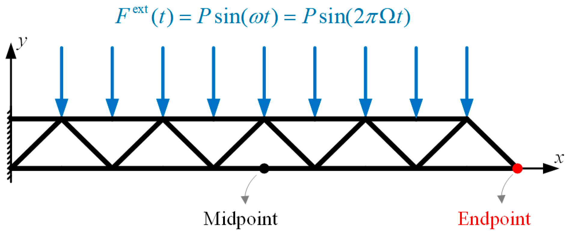
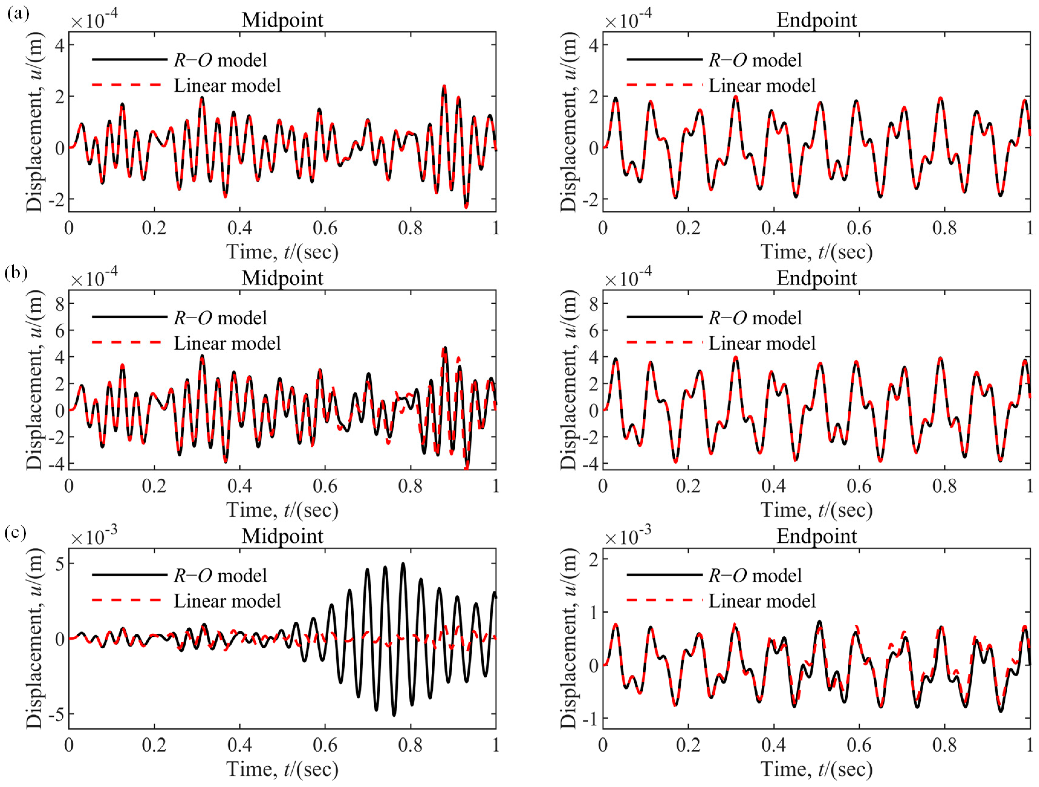
To investigate the influence of semi-rigid joints on the nonlinear dynamic response of the truss, a loading case, as shown in Figure 12, is considered. The micro-vibration load is a harmonic excitation of magnitude P = 5   N along the transverse direction. Three cases of loading frequencies are taken into account, i.e., Ω = 25 Hz, 50 Hz, and 75 Hz.
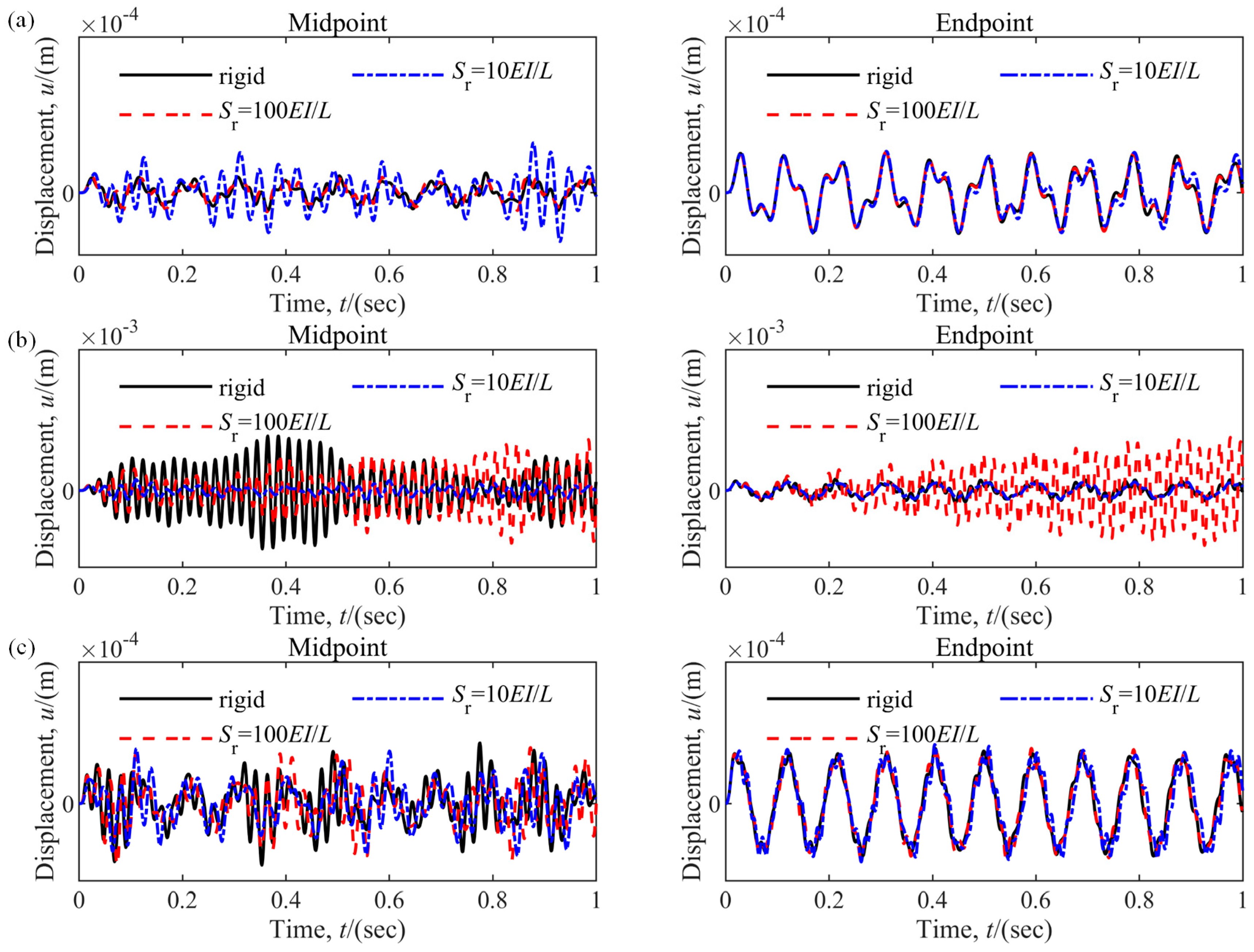
The displacement time histories of the midpoint and endpoint are computed and, respectively, depicted by solid and dashed lines, as shown in Figure 13. The results show that the rigid truss’s nonlinear dynamic responses and the semi-rigid truss with joint stiffness 100   E I / L are very close and share the same trend when the micro-vibration frequency is low, as the black and red lines show. As the joint stiffness reduces further, for example, to 10   E I / L , the dynamic response varies significantly. Figure 13a shows that the response increases significantly at the midpoint when Ω = 25 Hz compared to the other two cases of joint stiffness. As the exciting frequency comes to 50 Hz, a remarkable deviation in the vibration amplitude is observed in Figure 13b. It indicates that when the joint stiffness changes, the higher-order natural frequencies of the truss structure undergo significant changes (Figure 11), which affect the structural dynamic response of the structure under micro-vibration loads. As shown in Figure 13c, when Ω = 75 Hz, there is a significant difference in displacement response at the midpoint of the structure but not the endpoint.
The above results demonstrate that semi-rigid joints are of vital influence on the frequencies of each order of the structure, especially the high-order-dominated frequencies, compared with the ideal rigid connection. It also leads to a ‘closely spaced frequencies’ phenomenon and significantly varying dynamic responses. Semi-rigid joints can reduce the natural frequency of the structure, and, for in-orbit truss structures, subtle changes in natural frequency can also have a significant impact on the dynamic characteristics of the structure. At the same time, considering the high frequency of micro-vibration loads in spacecraft structures, the effects on the higher-order frequencies are bound to have a significant effect on the dynamic response of the structure. Therefore, it is necessary to conduct in-depth research on the joint performance of deployable truss structures.

4.2.2. Effects of Nonlinear Joint Stiffness

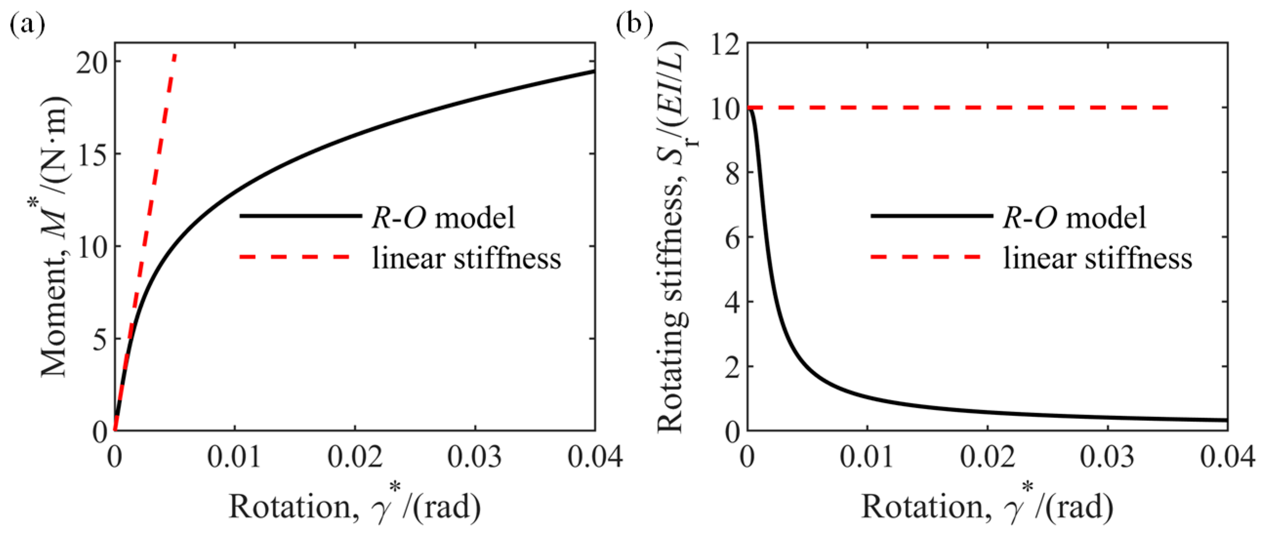
Due to clearance, friction, and other factors, the joint stiffness tends to be nonlinear rather than ideal linear [8]. The Ramberg–Osgood model [32] is a commonly used fitting model to describe nonlinear joint stiffness.
In this model, the rotating stiffness can be expressed as
S r = M 0 * / γ 0 * 1 + n M * / M 0 * n 1
where M 0 * denotes the reference moment, γ 0 * denotes the reference relative rotating angle, and n is a parameter describing the shape of the curve. These parameters are adopted in the following numerical analysis: M 0 * = 10 N·m, γ 0 * = 0.00245 rad, and n = 4. M 0 * / γ 0 * is set to 4080 N·m·rad−1 for comparison convenience, which is equivalent to 10   E I / L in Section 4.2.1. Then, the rotating stiffness is
S r = 4080 1 + 4 × 0.1 M * 3
and the corresponding moment–rotation curve and stiffness–rotation curve are shown in Figure 14.
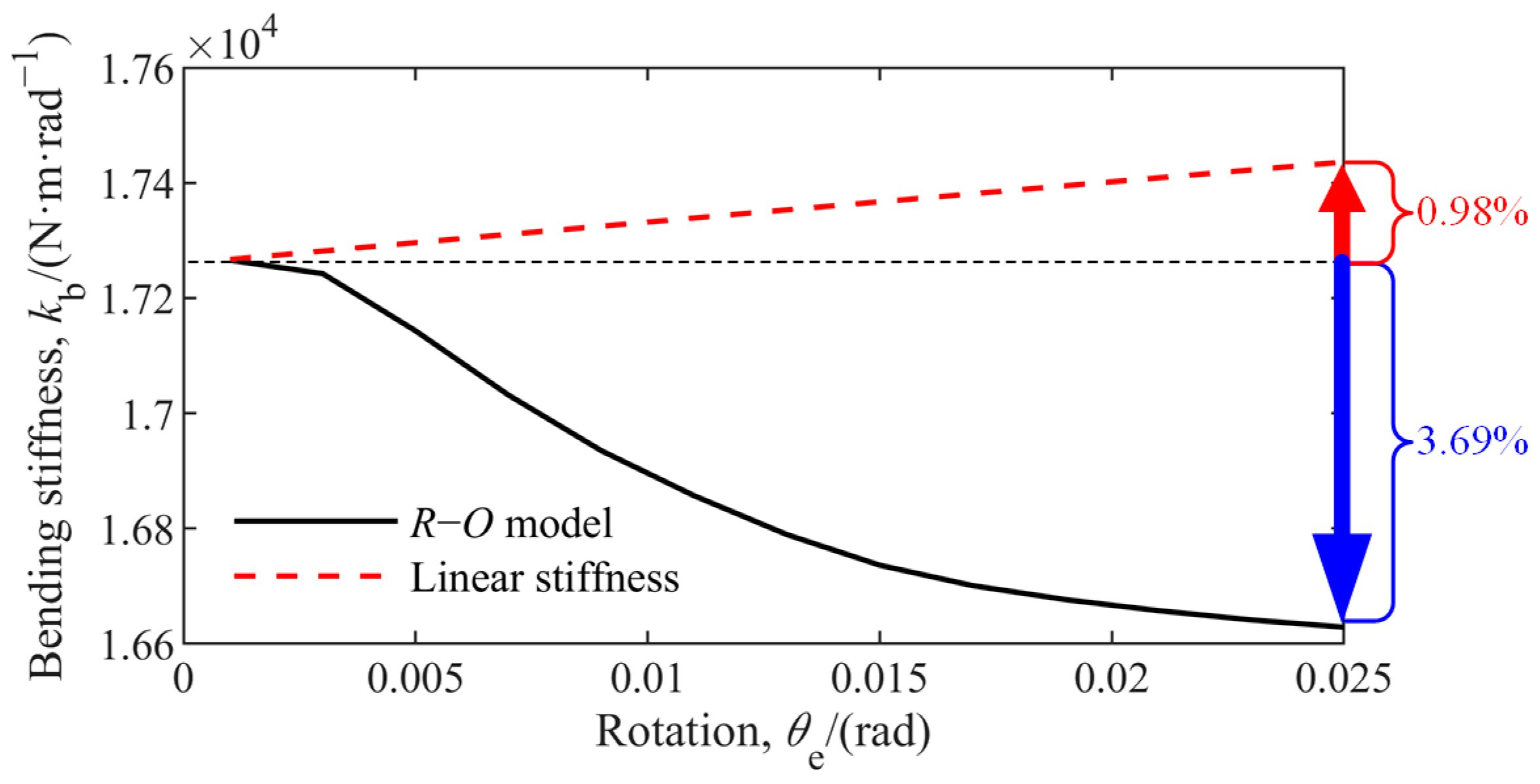
Utilizing the proposed model, the bending stiffness of the truss connected by nonlinear joints is computed and depicted in Figure 15. A notable phenomenon is observed that, instead of increasing as in the linear case, the bending stiffness of the truss decreases with the increase in the rotating angle. This value decreases by 3.69% when the rotating angle comes up to 0.025 rad. In contrast, it increases by 0.98% in the linear case. This result cautions engineers to care about the value of joint stiffness and its trend. Nonlinear joint stiffness may bring in unexcepted influences on the dynamics of trusses.
Figure 16 compares the dynamic responses of the two trusses of the same structure but different joint stiffness models, one linear and another nonlinear. When the external excitation is also small, the difference in displacement response of the structure is minor, as shown in Figure 16a. With the increase in the external load, it can be found that the distinction between the two joints grows. The distinction not only manifests in vibration amplitude but also in phase. For instance, as the external force increases from 2.5 N to 10 N, a significant difference can be observed in the midpoint displacement response of the two joint models (Figure 16a,b). In addition, an apparent phase difference is also observed at the endpoint, as shown in Figure 16c.
The results above demonstrate that the nonlinear joint stiffness has a variety of influences on both static characteristics and dynamic response. More importantly, these influences differ from one of the linear joints. The nonlinearity’s effect varies with the external load, changes vibration amplitude and phase, and depends on the structures’ instantaneous status.

4.2.3. Effects of the Size of Deployable Structure

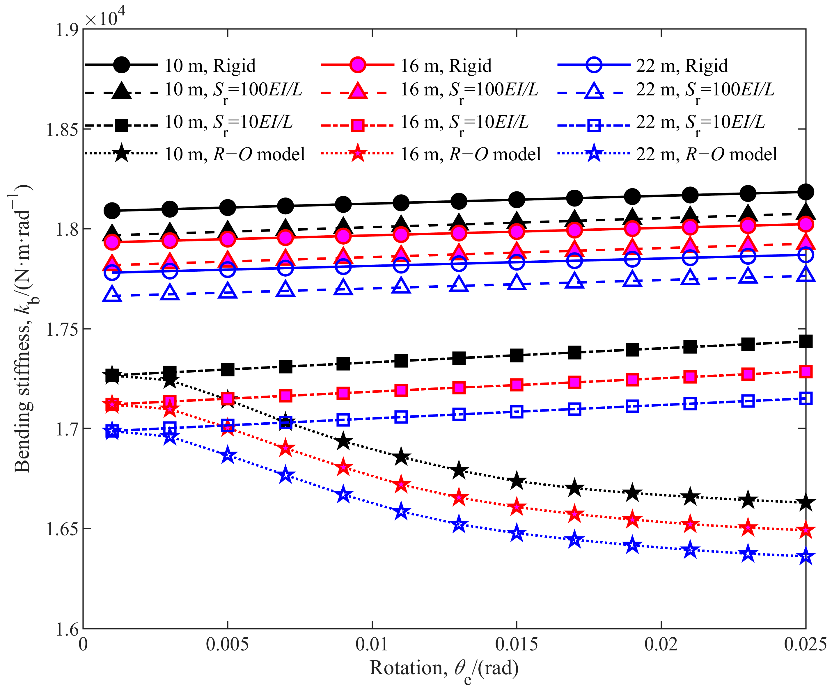
Whether the effect of semi-rigid joints varies as the size of the truss increases is investigated in this section, focusing on the effect on the bending stiffness of the whole truss. Three trusses of 10 m, 16 m, and 22 m lengths are considered. Figure 17 shows the variation in the bending stiffness of these trusses as their rotating angles increase. Table 2 compares the bending stiffness of the trusses of different joint stiffnesses, taking the corresponding rigid trusses as benchmarks. For the truss structure with rigid connection and linear connection stiffness, the stiffening phenomenon of the structure is observed again.
Moreover, for the truss structure with nonlinear connection stiffness, the nonlinear static characteristics of the structure are also consistent with the results obtained in Section 4.2.2. It can be found that the varying trends of the stiffnesses of the whole trusses have nothing with the lengths of the trusses. Compared to their corresponding rigid counterpart, the relative deviations of the trusses’ stiffness are independent of the lengths.
All of the numerical experiments demonstrate that joint stiffness must be considered in the dynamic analysis of truss structures, which significantly influences the prediction accuracy of static and dynamic problems.

5. Conclusions

This paper proposes a novel virtual connection element of three DOFs to model the semi-rigid joints, which widely exist in deployable truss structures but are usually tackled as ideal rigid connections in previous works. This modeling method is consistent for linear and nonlinear joints and is thus more efficient and realistic than traditional FEM. The linear and nonlinear additional joint moment formula is derived according to Hooke’s law and the Ramberg–Osgood model of rotating stiffness. Then, the governing equation of motion of the semi-rigid joints is established and integrated into the dynamic equation of the truss structure using the finite particle dynamic method. The motion constraints of joints with the components are taken into account. A series of numerical experiments are carried out to validate the accuracy and efficiency of the proposed model, including both static and dynamic problems.
The static and dynamic characteristics of a series of in-orbit deployable truss structures with semi-rigid joints are analyzed. The main conclusions of this work include the following:
1. A three-DOFs virtual connection element of Vector Form Intrinsic Finite Element is proposed to model semi-rigid joints. The proposed model can be used to evaluate the additional forces and moments caused by the deformation of semi-rigid joints and conveniently integrate them into the motion control equations of the nodes. The proposed method has been proven to be accurate and effective.
2. Semi-rigid joints exacerbate the effects of an in-orbit microvibration environment on the stability of deployable truss structures. Semi-rigid joints lower the dominant frequencies of structures, leading to a ‘closely-spaced-frequencies’ phenomenon and altering the dynamic responses significantly. Some high-order frequencies probably deviate by as much as 25~50%, demonstrating that the semi-rigid joints’ effect cannot be ignored for precise space structures.
3. The effects of semi-rigid joints on deployable truss structures is a long-term behavior. The increase in the joints’ rotating stiffness makes the whole truss’s stiffness increase in a step likewise form, ultimately approaching the value of the rigid-connected truss when the joint stiffness is higher than a certain value. This indicates a reasonable range of joint stiffness, where the relationship between structural stability and service life can be established correspondingly.
This paper demonstrates that semi-rigid joints must be considered in detail, instead of ideal rigid joints, both in static and dynamic problems of truss structures, since they can significantly influence the prediction accuracy of space structures. Based on the methodology proposed in this paper, further work will be dedicated to the dynamic responses of in-orbit structures with clearance joints and joint wear problems.

Author Contributions

Conceptualization, H.Y. and Y.H.; methodology, H.Y.; software, H.Y.; validation, H.Y.; formal analysis, H.Y., Y.H. and L.L.; investigation, H.Y.; resources, W.M.; data curation, Y.H. and Y.Z.; writing—original draft preparation, H.Y.; writing—review and editing, Y.H., W.M., L.L. and Y.Z.; visualization, Y.H.; supervision, W.M.; project administration, Y.Z.; funding acquisition, Y.Z. All authors have read and agreed to the published version of the manuscript.

Funding

This research was funded by the National Natural Science Foundation of China, grant number U21B2075.

Data Availability Statement

The data used to support the findings of this study are available from the corresponding author upon request.

Conflicts of Interest

The authors declare no conflict of interest.

References

  1. Thornton, E.A.; Paul, D.B. Thermal-structural analysis of large space structures-an assessment of recent advances. J. Spacecr. Rocket. 1985, 22, 385–393. [Google Scholar] [CrossRef]
  2. Li, T.; Jiang, J.; Deng, H.; Lin, Z.; Wang, Z. Form-finding methods for deployable mesh reflector antennas. Chin. J. Aeronaut. 2013, 26, 1276–1282. [Google Scholar] [CrossRef]
  3. Xu, Y.; Guan, F.; Chen, J.; Zheng, Y. Structural design and static analysis of a double-ring deployable truss for mesh antennas. Acta Astronaut. 2012, 81, 545–554. [Google Scholar] [CrossRef]
  4. Zhang, J.; Deng, Z.; Guo, H.; Liu, R. Equivalence and dynamic analysis for jointed trusses based on improved finite elements. Proc. Inst. Mech. Eng. Part K J. Multi-Body Dyn. 2014, 228, 47–61. [Google Scholar] [CrossRef]
  5. Liu, M.; Cao, D.; Zhu, D. Equivalent dynamic model of the space antenna truss with initial stress. AIAA J. 2020, 58, 1851–1863. [Google Scholar] [CrossRef]
  6. Siriguleng, B.; Zhang, W.; Liu, T.; Liu, Y. Vibration modal experiments and modal interactions of a large space deployable antenna with carbon fiber material and ring-truss structure. Eng. Struct. 2020, 207, 109932. [Google Scholar] [CrossRef]
  7. Zhang, W.; Xi, A.; Siriguleng, B.; Liu, G. An equivalent cylindrical shell model of vibration analysis based on simplified repeating unit cell for ring truss structure. J. Sound Vib. 2019, 459, 114847. [Google Scholar] [CrossRef]
  8. Guo, H.; Zhang, J.; Liu, R.; Deng, Z. Effects of joint on dynamics of space deployable structure. Chin. J. Mech. Eng. 2013, 26, 861–872. [Google Scholar] [CrossRef]
  9. Quinn, D.D. Modal analysis of jointed structures. J. Sound Vib. 2012, 331, 81–93. [Google Scholar] [CrossRef]
  10. Mohammed, D.R.; Ismael, M.A. Effect of Semi-rigid Connection on Post-buckling Behavior of Braced-Steel Frames. In Proceedings of AICCE’19: Transforming the Nation for a Sustainable Tomorrow 4; Springer International Publishing: Berlin/Heidelberg, Germany, 2020; pp. 547–556. [Google Scholar]
  11. van Keulen, D.C.; Nethercot, D.A.; Snijder, H.H.; Bakker, M. Frame analysis incorporating semi-rigid joint action: Applicability of the half initial secant stiffness approach. J. Constr. Steel Res. 2003, 59, 1083–1100. [Google Scholar] [CrossRef]
  12. Al-Bermani, F.G.A.; Kitipornchai, S. Elastoplastic nonlinear analysis of flexibly jointed space frames. J. Struct. Eng. 1992, 118, 108–127. [Google Scholar] [CrossRef]
  13. Tin-Loi, F.; Misa, J.S. Large displacement elastoplastic analysis of semi-rigid steel frames. Int. J. Numer. Methods Eng. 1996, 39, 741–762. [Google Scholar] [CrossRef]
  14. Shi, G.; Atluri, S.N. Static and dynamic analysis of space frames with nonlinear flexible connections. Int. J. Numer. Methods Eng. 1989, 28, 2635–2650. [Google Scholar] [CrossRef]
  15. Kawashima, S.; Fujimoto, T. Vibration analysis of frames with semi-rigid connections. Comput. Struct. 1984, 19, 85–92. [Google Scholar] [CrossRef]
  16. Chan, S.L. Vibration and modal analysis of steel frames with semi-rigid connections. Eng. Struct. 1994, 16, 25–31. [Google Scholar] [CrossRef]
  17. Chui PP, T.; Chan, S.L. Transient response of moment-resistant steel frames with flexible and hysteretic joints. J. Constr. Steel Res. 1996, 39, 221–243. [Google Scholar] [CrossRef]
  18. Živković, S.; Stojković, N.; Spasojević-Šurdilović, M. Global analysis of steel constructions with semi-rigid connections. Teh. Vjesn. 2020, 27, 951–960. [Google Scholar]
  19. Blandford, G.E. Progressive failure analysis of inelastic space truss structures. Comput. Struct. 1996, 58, 981–990. [Google Scholar] [CrossRef]
  20. Tada, M.; Suito, A. Static and dynamic post-buckling behavior of truss structures. Eng. Struct. 1998, 20, 384–389. [Google Scholar] [CrossRef]
  21. Ting, E.C.; Shih, C.; Wang, Y.K. Fundamentals of a vector form intrinsic finite element: Part I. Basic procedure and a plane frame element. J. Mech. 2004, 20, 113–122. [Google Scholar] [CrossRef]
  22. Ting, E.C.; Shih, C.; Wang, Y.K. Fundamentals of a vector form intrinsic finite element: Part II. Plane solid elements. J. Mech. 2004, 20, 123–132. [Google Scholar] [CrossRef]
  23. Shih, C.; Wang, Y.K.; Ting, E.C. Fundamentals of a vector form intrinsic finite element: Part III. Convected material frame and examples. J. Mech. 2004, 20, 133–143. [Google Scholar] [CrossRef]
  24. Wu, T.Y.; Tsai, W.C.; Lee, J.J. Dynamic elastic–plastic and large deflection analyses of frame structures using motion analysis of structures. Thin-Walled Struct. 2009, 47, 1177–1190. [Google Scholar] [CrossRef]
  25. Li, X.; Guo, X.; Guo, H. Vector form intrinsic finite element method for nonlinear analysis of three-dimensional marine risers. Ocean Eng. 2018, 161, 257–267. [Google Scholar] [CrossRef]
  26. Lien, K.H.; Chiou, Y.J.; Wang, R.Z.; Hsiao, P.A. Vector form intrinsic finite element analysis of nonlinear behavior of steel structures exposed to fire. Eng. Struct. 2010, 32, 80–92. [Google Scholar] [CrossRef]
  27. Duan, Y.F.; He, K.; Zhang, H.M.; Ting, E.C.; Wang, C.Y.; Chen, S.K.; Wang, R.Z. Entire-process simulation of earthquake-induced collapse of a mockup cable-stayed bridge by vector form intrinsic finite element (VFIFE) method. Adv. Struct. Eng. 2014, 17, 347–360. [Google Scholar] [CrossRef]
  28. Wang, R.Z.; Tsai, K.C.; Lin, B.Z. Extremely large displacement dynamic analysis of elastic–plastic plane frames. Earthq. Eng. Struct. Dyn. 2011, 40, 1515–1533. [Google Scholar] [CrossRef]
  29. Türker, T.; Kartal, M.E.; Bayraktar, A.; Muvafik, M. Assessment of semi-rigid connections in steel structures by modal testing. J. Constr. Steel Res. 2009, 65, 1538–1547. [Google Scholar] [CrossRef]
  30. Zhou, Z.H.; Chan, S.L. Self-equilibrating element for second-order analysis of semi-rigid jointed frames. J. Eng. Mech. 1995, 121, 896–902. [Google Scholar] [CrossRef]
  31. Williams, F.W. An approach to the nonlinear behaviour of the members of a rigid jointed plane framework with finite deflections. Q. J. Mech. Appl. Math. 1964, 17, 451–469. [Google Scholar] [CrossRef]
  32. Ramberg, W.; Osgood, W.R. Description of Stress-Strain Curves by Three Parameters; Technical Note; National Advisory Committee for Aeronautics: Washington, DC, USA, 1943. [Google Scholar]
Figure 1. A deployable structure with semi-rigid joints. (a) Deployable space structure under working conditions; (b) Deployment process of deployable structure; (c) Deformation of structure; (d) Semi-rigid joint; (e) Several semi-rigid joints.
Aerospace 10 00821 g001
Figure 2. Elements a and b are connected by joint χ. The joint can be modeled as a 3-DOFs spring system without mass and length. The spring system has two translational and one rotational stiffness.
Aerospace 10 00821 g002
Figure 3. The structure is discretized into finite particles. Elements connect the particles. The motion of particles follows Newton’s mechanics law.
Aerospace 10 00821 g003
Figure 4. Reverse motion and pure deformation.
Aerospace 10 00821 g004
Figure 5. Modeling and solving procedures.
Aerospace 10 00821 g005
Figure 6. Comparison of the results obtained by using FPDM and those in literature. The solid line and dashed line in the plot represent the result of FPDM, and markers represent the result in Ref. [30].
Aerospace 10 00821 g006
Figure 7. Comparison of results of the loaded point displacement of FPDM and the published results. The solid line and dashed line in the plot represent the result of FPDM, and markers represent the result in Refs. [30,31]. (a) Load-displacement of loaded point; (b) Moment-displacement of loaded point.
Aerospace 10 00821 g007
Figure 8. Comparison of nonlinear responses obtained by the FPDM and those listed in the literature. The solid line and dashed line in the plot represent the result of FPDM, and markers represent the result in Ref. [17]. (a) Load-displacement of central point; (b) Displacement-time of central point.
Aerospace 10 00821 g008
Figure 9. Comparison of bending stiffness with different joints. (a) Bending behavior of truss structure; (b) Bending stiffness–rotation curves; (c) Bending stiffness–rotating stiffness curves.
Aerospace 10 00821 g009
Figure 10. Nonlinear dynamic responses of the free oscillating truss structure. (a) Rigid joints; (b) Semi-rigid joints, S r = 100   E I / L ; (c) Semi-rigid joints, S r = 10   E I / L .
Aerospace 10 00821 g010
Figure 11. High-order frequencies and ‘closely spaced frequencies’ intervals Ωt with different joint stiffness. (a) Rigid joints; (b) Semi-rigid joints, S r = 100   E I / L ; (c) Semi-rigid joints, S r = 10   E I / L .
Aerospace 10 00821 g011
Figure 12. Harmonic excitation force subjected to the truss structure.
Aerospace 10 00821 g012
Figure 13. Nonlinear dynamic responses of truss structure under different frequencies of external force. (a) Ω = 25 Hz; (b) Ω = 50 Hz; (c) Ω = 75 Hz.
Aerospace 10 00821 g013
Figure 14. Comparison of connection stiffness of nonlinear Ramberg–Osgood model and linear stiffness model. (a) Relationship of moment and rotation angle; (b) Relationship of rotating stiffness and rotation angle.
Aerospace 10 00821 g014
Figure 15. Comparison of bending stiffness of the truss with the nonlinear Ramberg–Osgood model and linear stiffness model.
Aerospace 10 00821 g015
Figure 16. Comparison of nonlinear dynamic responses of the truss structure with linear and nonlinear rotating stiffness, Ω = 25 Hz. (a) P = 2.5 N; (b) P = 5 N; (c) P = 10 N.
Aerospace 10 00821 g016
Figure 17. Comparison of bending stiffness for the truss with different lengths and joints.
Aerospace 10 00821 g017
Table 1. Geometric and material parameters of the truss structure.
ComponentParameterValue
Transverse beamLength L1 (m)1
Outer diameter d1 (m)0.04
Thickness δ1 (m)0.003
Young’s modulus E1 (Pa)6.8 × 10¹⁰
Poisson ratio μ10.3
Density ρ1 (kg/m3)2500
Diagonal beamLength L2 (m)1.414
Outer diameter d2 (m)0.04
Thickness δ2 (m)0.003
Young’s modulus E2 (Pa)6.8 × 10¹⁰
Poisson ratio μ20.3
Density ρ2 (kg/m3)2500
Semi-rigid jointsEquivalent mass m1 (kg)0.1392
Rigid jointsEquivalent mass m2 (kg)0.1927
Table 2. Bending stiffness (N·m·rad−1) and decline ratio (%).
Length (m)RigidSr = 100 EI/LSr = 10 EI/LRamberg–Osgood Model
ResultResultDiff (%)ResultDiff (%)ResultDiff (%)
1018,184.118,075.2−0.59917,436.1−4.11316,628.7−8.554
1618,022.817,924.9−0.54317,285.9−4.08916,490.8−8.500
2217,869.617,763.8−0.59217,149.7−4.02916,360.2−8.447
Disclaimer/Publisher’s Note: The statements, opinions and data contained in all publications are solely those of the individual author(s) and contributor(s) and not of MDPI and/or the editor(s). MDPI and/or the editor(s) disclaim responsibility for any injury to people or property resulting from any ideas, methods, instructions or products referred to in the content.