Article

Aerodynamic Instabilities in High-Speed Air Intakes and Their Role in Propulsion System Integration

by
Aristia L. Philippou
*,
Pavlos K. Zachos
and
David G. MacManus
Centre for Propulsion and Thermal Power Engineering, School of Aerospace, Transport and Manufacturing, Cranfield University, Cranfield MK43 0AL, UK
*
Author to whom correspondence should be addressed.
Aerospace 2024, 11(1), 75; https://doi.org/10.3390/aerospace11010075
Submission received: 17 October 2023 / Revised: 28 December 2023 / Accepted: 28 December 2023 / Published: 12 January 2024

Abstract

:
High-speed air intakes often exhibit intricate flow patterns, with a specific type of flow instability known as ‘buzz’, characterized by unsteady shock oscillations at the inlet. This paper presents a comprehensive review of prior research, focused on unraveling the mechanisms that trigger buzz and its implications for engine stability and performance. The literature survey delves into studies concerning complex-shaped diffusers and isolators, offering a thorough examination of flow aerodynamics in unstable environments. Furthermore, this paper provides an overview of contemporary techniques for mitigating flow instability through both active and passive flow control methods. These techniques encompass boundary layer bleeding, the application of vortex generators, and strategies involving mass injection and energy deposition. The study concludes by discussing future prospects in the domain of engine-intake aerodynamic compatibility. This work serves as a valuable resource for researchers and engineers striving to address and understand the complexities of high-speed air induction systems.

1. Introduction

Air induction systems (AIS), also commonly known as intakes or inlets, are critical parts in propulsion system integration and play a key role to an efficient engine operation. Air intakes supply the required amount of airflow to the engine and ensure that the air at the face of the compressor is uniformly distributed. Compatibility between the AIS and the propulsion system across the required operating range of the air vehicle is a key factor in ensuring a good engine performance and operability. The airflow reaching the engine face must have optimum levels of pressure, temperature, and velocity to ensure good engine performance and stability. The mass flow requirement can vary across a flight envelope, so the intake must adapt to the engine’s needs and have the flexibility to operate in different flight speed regimes, aircraft thrust requirements, and onset flow characteristics. For example, subsonic transport spends most of its flying time at a specific altitude and cruising speed at subsonic speed, making the intake-engine matching relatively more simple compared to aircraft with multi-mission capabilities [1]. The latter requires a more complex air induction system with a wider operating range compared to the subsonic transport.
The intake must decelerate the incoming flow to a subsonic speed prior to delivering it to the engine. This compression occurs either through a normal shock or a series of oblique shocks. Supersonic intakes are divided into three categories depending on the location of supersonic diffusion (see Figure 1). In external compression intakes, the diffusion occurs with a series of oblique shock waves followed by a normal shock external to the duct. In internal compression intakes, the diffusion occurs through a series of oblique shock waves followed by a normal shock, within the duct, while in a mixed compression intake, the diffusion occurs partly within the duct. Details about these three distinct types of intakes have been previously provided in numerous past works; the reader is referred to [2,3,4].
As flight conditions vary, the intake should be able to deliver the required flow uniformity conditions at the engine face. For the design Mach number, the intake is said to operate at a critical condition when the normal shock is very near or attached to the cowl lip. The flow ratio, A /A c , in this case, is at or near its maximum value of (A /A c ) m a x = 1.0. In this case, the engine utilizes the ingested captured mass flow. For the case where the normal shock is drawn within the diffuser, this region of operation is termed supercritical. In this operating condition, the pressure recovery reduces without increasing the absolute airflow rate above the critical value. If the freestream flow area A is less than the intake captured area A c , the normal shock lies upstream of the cowl lip. This is known as the subcritical operation. The different modes of operation are graphically shown in Figure 2, which summarizes the operating conditions of an external compression intake across the range of flow ratios. This is where the intake-engine matching is of critical importance since the intake must be able to provide sufficient pressure recovery and flow uniformity at supersonic off-design conditions, keeping losses to a minimum.
When the intake operates under extremely subcritical conditions outside its established operational boundaries, there is a significant degradation in flow quality, which poses challenges to the overall intake operation. The quality of the flow at an engine face is generally characterized by the uniformity of the total pressure profile and the angularity of the velocity field expressed as the distribution of the swirl angle across the plane [5,6,7,8]. External compression supersonic intakes typically show acceptable performance near and around the critical point but may exhibit various instabilities when operating under subcritical conditions. When the mass flow ratio is significantly reduced, the intake is choked, and the shock system is expelled out along with flow spillage, causing the intake to operate in the so-called “unstart mode”. An intake can unstart for several reasons, for example, due to the over-contraction of the captured stream tube, off-design angle of attack, back pressure variation, and perturbations in the combustor. Intake unstarting has been investigated in the past by numerous researchers [9,10,11,12,13,14,15]. The intake starting ability is typically evaluated using the Kantrowitz and isentropic limits, both of which indicate that it depends on the internal contraction ratio [16,17]. Timofeev et al. [10] summarized various starting techniques in high-contraction high-speed intakes involving overboard spillage and wall perforations, and proposed new approaches using unsteady effects. Instabilities can potentially occur in the form of a self-sustained oscillation of the shock system attached at the supersonic entry of the intake. The shock system is alternately swallowed and expelled by the inlet. At a critically low mass flow ratio, strong, unsteady shock oscillations may develop. These oscillations have the potential to deteriorate the pressure recovery and induce significant flow distortion at the engine face, which can prove detrimental to the engine’s performance. This phenomenon is commonly known as “buzz” and was first observed and analytically described by Oswattisch [18] in the 1940s.
Flow unsteadiness and distortion present in an intake can penalize the propulsion system efficiency, operability, and stability margins of the engine. Flow distortion refers to the non-uniformity of the flow upstream an aero-engine and typically arises from the design of the airframe and propulsion systems, or during flight maneuvers, crosswind, and flight at high angles of attack. High-speed intakes operating at off-design conditions may face shock-induced separation, lip separation, and secondary internal flows contributing to flow distortion. This promotes fluctuations in the total pressure, temperature, and velocity, which can adversely affect the engine, potentially leading to compressor stall or, in more severe cases, engine surge [19,20]. Total pressure fluctuations generated in supersonic intakes could also limit its compatibility with a turbo-engine of a propulsion system. Therefore, it is of paramount importance to study and characterize the complex unsteady distorted patterns produced at the aerodynamic interface plane (AIP), that is the interface between the incoming airflow and the engine face. Flow distortion can be classified into three categories: total pressure, total temperature, and swirl distortion [6,7,8]. Previous work related to the flow behavior in subsonic convoluted diffusers during unsteady operations demonstrate that the engine’s performance and stability are significantly impacted by the distorted flow [21,22,23,24]. The total pressure distortion descriptors were once considered an acceptable representation of the flow field, but evidently, even with a benign total pressure distortion profile, the swirl composition of the flow field could show significant asymmetries [25]. Depending on the distribution of the swirl angle and the swirl pattern portrayed, the effect on the turbo-machinery aerodynamics may differ [26].
Conventional assessments of supersonic intakes typically considered two types of swirl distortion: paired swirl and bulk swirl [8]. The intake geometry greatly influences the swirl distortion levels, as highly-offset convoluted intakes typically exhibit greater distortions than low-offset ducts [27]. The study of intake swirl is of paramount importance due to its role as a significant disturbance parameter, which can potentially lead to substantial challenges in ensuring compatibility between the engine and the intake system. This compatibility issue becomes especially critical when considering the intricacies of engine fan operation, where the effects of intake swirl can have pronounced repercussions on the overall performance and efficiency. This phenomenon has been evident in several historical case studies involving a range of aircraft turbine engine applications. An example case involved the Tornado twin-engine aircraft, where during the early intake-model testing, while the full-scale tests did not show evidence of intake-engine compatibility issues, the prototype flight testing resulted in engine surges at subsonic and supersonic flight speeds [8]. The compatibility between the intake and the propulsion system is, therefore, vital when dealing with such a wide range of operating conditions. Therefore, a comprehensive understanding of intake swirl is essential in addressing and mitigating the potential issues that may arise during engine fan operation within the broader context of propulsion system optimization and reliability.
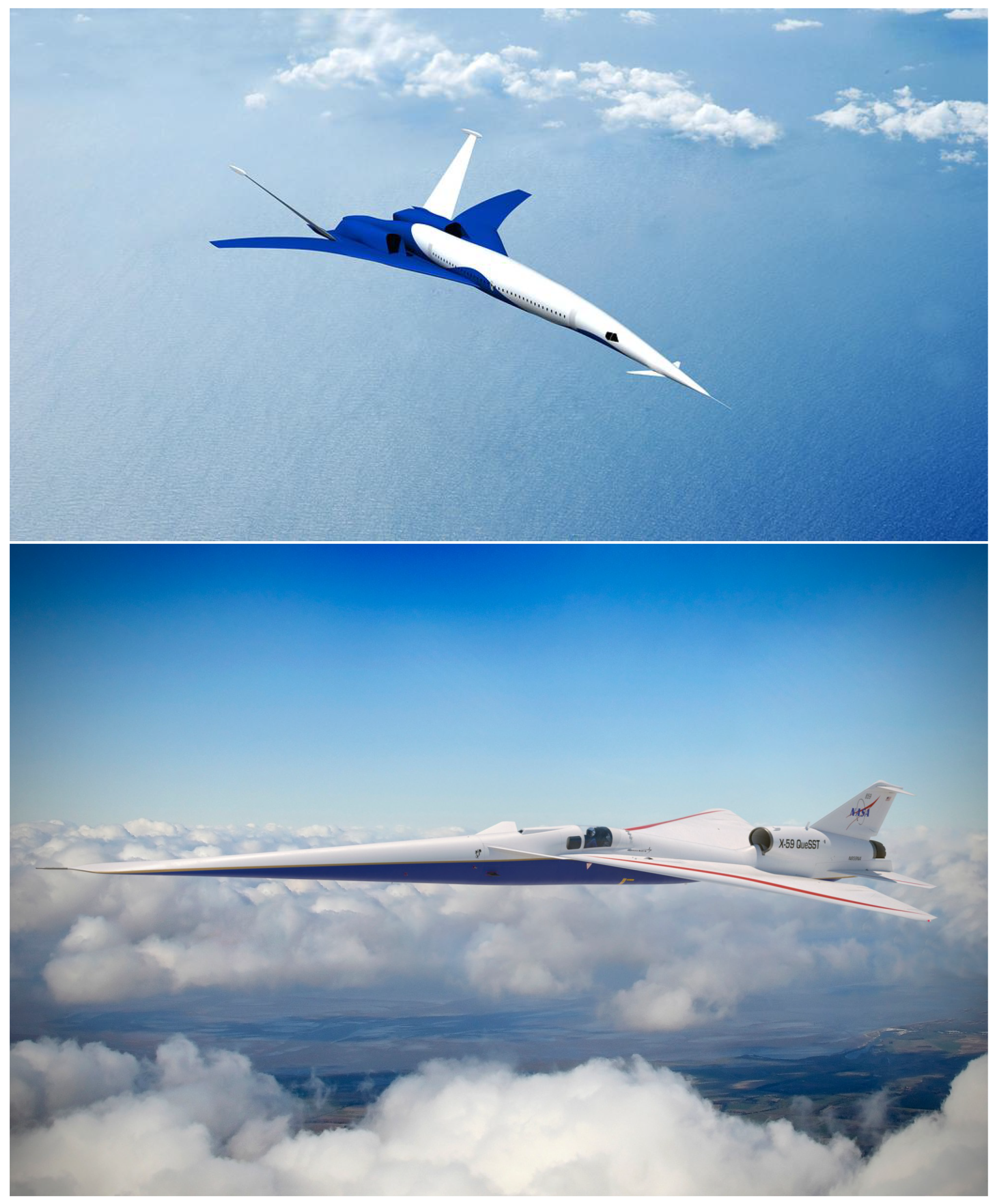
The significance of compatibility considerations becomes increasingly pronounced when delving into the realm of cutting-edge designs for the future. This is particularly evident in scenarios where the propulsion system is integrated into the airframe (Figure 3). The seamless integration of these essential components not only marks a departure from conventional aircraft configurations but also introduces a set of challenges, with a focal point on the inter-relationship between the propulsion system and the airframe. The core of the matter lies in the fact that this airframe/engine coupling complicates significantly the characteristics of the incoming airflow, and in turn, promotes the development of inlet flow distortion. Flow distortion occurs when the air entering the propulsion system encounters disruptions due to the complex geometries and interactions within the integrated design. These disruptions can manifest as variations in pressure, temperature, and velocity across different regions of the airflow. Understanding and managing flow distortion is paramount as it directly influences the efficiency and performance of the propulsion system. Distorted airflow can lead to uneven pressure distributions, affecting the engine’s combustion process and subsequently impacting thrust generation. The intricate coupling of the propulsion system with the airframe demands a holistic approach to design and engineering to ensure both components function synergistically without compromising safety or performance. The delicate balance between propulsion integration and flow dynamics becomes a critical aspect of the overall design philosophy. Addressing these challenges is pivotal, for the successful realization of aircraft designs.
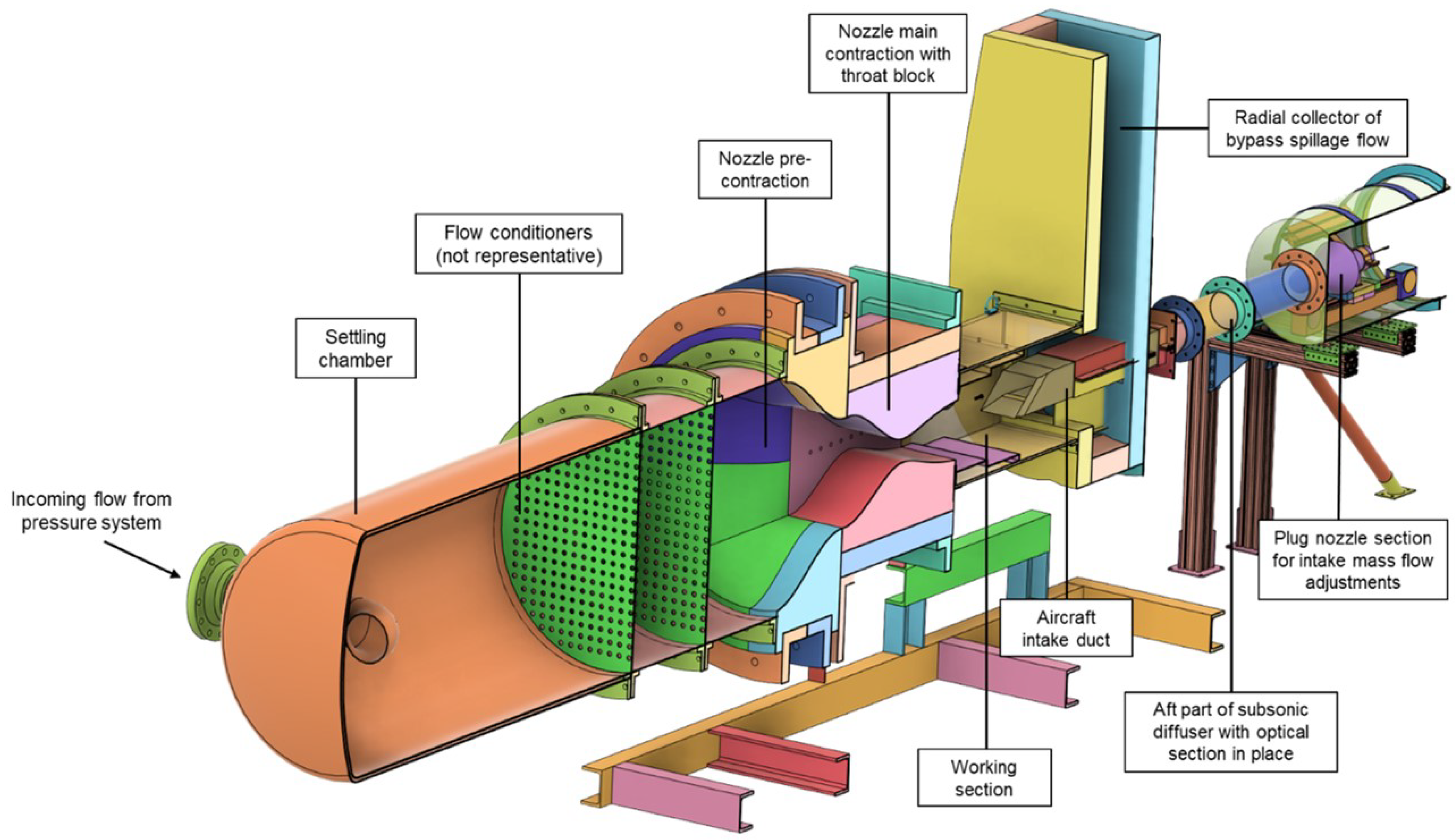
This paper offers a holistic perspective on the challenges posed by aerodynamic instabilities associated with off-design conditions in high-speed intakes, covering a wide range of relevant topics. The discussion encompasses a detailed exploration of supersonic and hypersonic intake buzz, with an extensive review of relevant literature. Additionally, the paper delves into the study of flow unsteadiness in isolators and the dynamic distortion experienced in convoluted intakes to draw information on the flow topology and behavior downstream of the shock system oscillations, and similarly, on how dynamic distortion can affect the engine’s operability. Furthermore, the paper addresses the impact of operating conditions on intake buzz and explores strategies for mitigating the unsteady flow operation. The last part of the paper concludes with recommendations for future research endeavors aimed at advancing our understanding of unsteady high-speed intake flow behavior. More specifically, it focuses on the role of small-scale experimental test rigs that have been previously shown as an effort to characterize these instabilities. Small-scale testing, at an early stage of the intake-engine integration process, was found able to provide insights into engine-intake compatibility in a more cost-effective way than full-scale wind-tunnel campaigns. A few of these test rigs have previously been reported; however, none of these fulfilled their initial design intent due to operational complexities that limited either the achievable operating range of the test model or the representativeness of the model’s aerodynamics due to working section wall interference [28,29,30]. As such, a bespoke capability is still required to reproduce and characterize as faithfully as possible the unsteady distortions in supersonic intakes, the interactions with the diffuser flow upstream of the propulsion system, and to establish methods to aid the design and integration of future propulsion systems.

2. Flow Instabilities in Air Induction Systems

2.1. Physics and Characterization of Intake Buzz

Intake buzz became a topic of interest for the scientific community in the 1950s, mostly in relation to applications on ramjets with axisymmetric and conical center bodies. Over time, the research on the supersonic buzz phenomenon has focused on three different (but highly linked) areas: (a) detection of the trigger mechanisms, (b) analysis of pertinent unsteady flow characteristics, and (c) investigation into several approaches to suppress or prevent its detrimental influence to engine stability and performance. However, there is very little work shown in the area of linking buzz-related unsteadiness to the dynamic distortions encountered at the engine face. Hence, the previously described requirement of small-scale testing focused on characterizing the nature of a buzzing air intake in relation to unsteady inlet flow distortion at the engine face.
Initially, the main point of interest was understanding the triggering mechanism of buzz and its origin. The two main types of shock instability were observed by Ferri and Nucci [31] and Dailey [32]. Ferri and Nucci [31] performed a series of experimental tests to obtain the optimum pressure recovery for low-drag inlets in the range of onset Mach numbers between 2.45 and 3.30. They concluded that frontal shock fluctuations and internal mass flow variations occur in the presence of vortex shedding moving to the lower cowl lip surface. This phenomenon stems from the collision between the reflected oblique shock and the normal shock. Also, these oscillations happen only when the internal flow is fully subsonic, and disturbances are transmitted upstream. This occurrence is now commonly referred to as the Ferri criterion [31]. Later on, Fisher [33] studied the Ferri criterion and elaborated further on the connection between the shock unsteadiness and the severity of the shear zone, in terms of the total pressure gradient across the zone. According to Fisher, a change in total pressure across the shear zone may cause instability if the ratio between the total pressure differential across the shear zone to the freestream total pressure is at least 7%. The Dailey criterion was first introduced in 1954 [32], and as Ferri suggested, buzz also begins when the steady subcritical operation is interrupted by the choking of the inlet. Only the trigger of buzz is now related to the flow separation over the compression surface due to the interaction between the normal shock and the boundary layer. Figure 4 depicts the two known triggering mechanisms of buzz, the Ferri and Dailey criterion, as represented in the later work by Jungclaus [34] and Fisher and Neale [33].
Orlin and Dunsworth [35] focused on the relationship between the variation in intake static pressure and mass flow ratio. Their study revealed that shock unsteadiness resulted when the slope of the static pressure characteristic at the intake entrance changed from negative to positive with a reduction in flow ratio. This phenomenon is commonly referred to as the pressure slope criterion. In other words, the flow remains stable when the static pressure slope remains positive, regardless of the ingestion of the vortex sheet, otherwise, a negative static pressure slope implies the risk of instability below a certain mass flow rate.
Currently, it is generally accepted that two types of intake buzz exist, known as “little buzz” and “big buzz”. Little buzz is typically described by the Ferri criterion, while big buzz is typically described by the Dailey criterion. With a gradual reduction in mass flow, low amplitude oscillation, the so-called little buzz, occurs. Little buzz involves a shear zone formed due to the intersection of the lambda foot of the normal shock, having a steep total pressure gradient across its width. When in contact with or close to the cowl lip, this can cause flow instability. With further reduction of the mass flow, larger amplitude oscillations occur, the so-called big buzz [33]. This phenomenon is characterized by a wider range of shock movement, a shock expulsion at the entrance of the intake and repositioning of the shock system, followed by swallowing of the shock in the intake, as the flow attempts to restore the initial shock system by adjusting the pressure field. Isolated cycle oscillations are encountered during the big buzz. In the study of Soltani et al. [36], the position of the shock system over the duration of a full big buzz cycle was shown upstream of an axisymmetric supersonic intake via a sequence of Schlieren images.
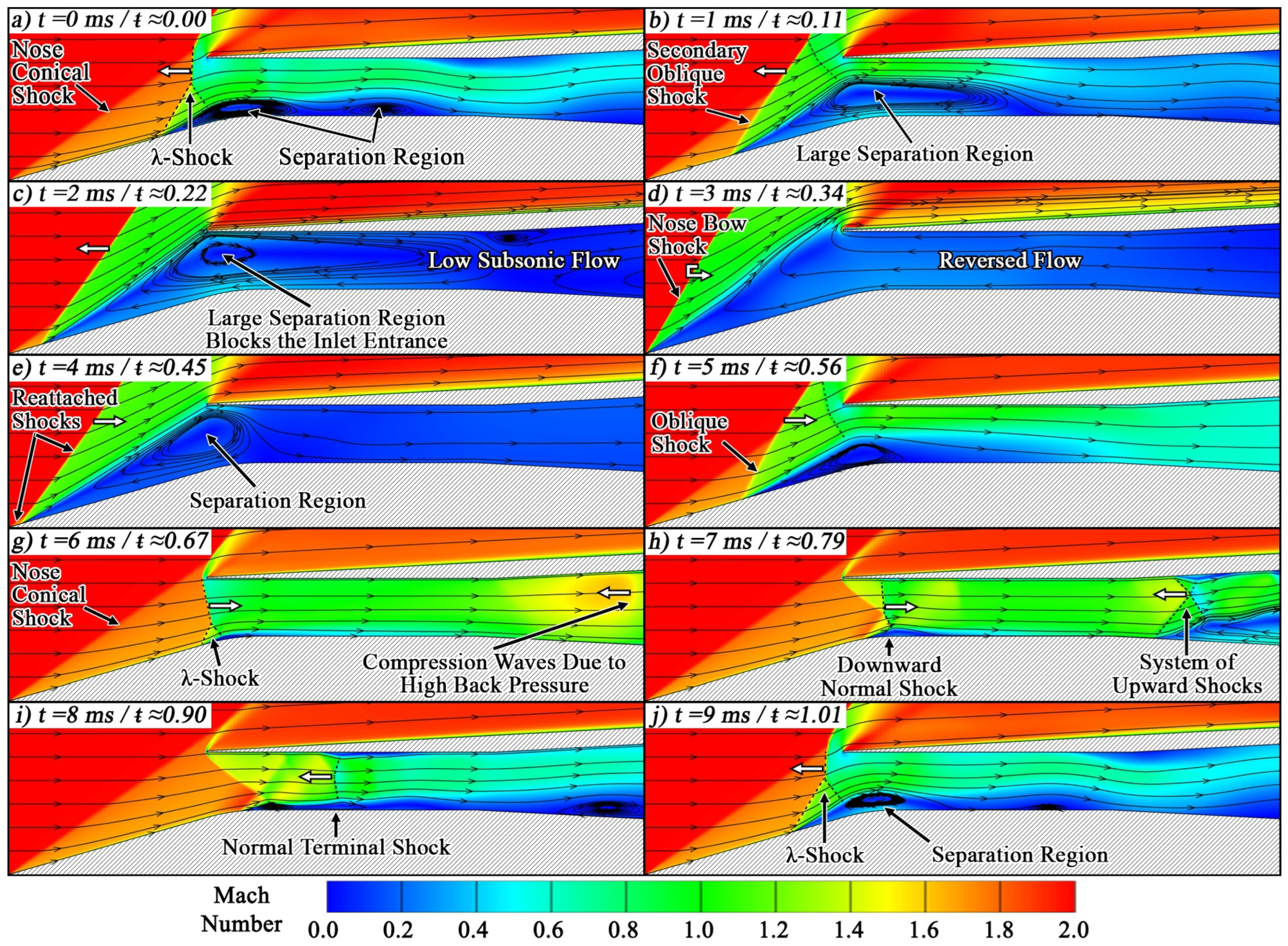
Although numerous researchers have delved into the phenomenon of buzz, a comprehensive and satisfactory definition of the buzz flow characteristics over a complete buzz cycle remains elusive. Instead, various studies have offered fragmented descriptions of the flow behavior and shock movements observed in their respective investigations. Soltani and Younsi [37] were the first to provide a thorough buzz cycle description observed at M = 1.8 for a mixed compression intake. As quoted in Soltani’s work: “The cycle begins when the normal shock stands at its closest distance to the throat, with high-pressure flow within the intake pushing the normal shock to move forward. The separation region and flow spillage around the cowl lip increases when the normal shock moves upstream, while the intake mass flow rate and total pressure decrease. As the normal shock is at its most upstream position, it coincides with the conical shock which strengthens the shock. A large separation behind the shockwave that covers the entire intake flow field appears for a short time and the intake mass flow rate is now at its minimum value. The small mass flow rate and low static pressure inside the intake lead to swallowing of the separated flow inside the intake causing the shock to move downstream. The normal shock is now weakened and returns to its original position, while the intake mass flow rate and total pressure reach again their maximum values”. Abedy et al. [38] recently described a slightly different buzz cycle, which is shown in Figure 5. The cycle again begins with the normal shock being the closest to the throat, and due to the high back pressure, the normal shock is pushed upstream with a large separation inside the diffuser that effectively chokes the intake entrance area. Due to the adverse pressure gradient, the shock system is now swallowed back inside the intake, steering the intake into a supercritical operation. Compression waves are reflected upstream, and when combined, they form a system of two oblique shocks and a terminal normal shock. A similar shock structure now appears in the transonic throat too due to the downstream low-pressure field. Finally, the two systems are merged downstream of the throat and the shock system returns to its original subcritical position.
Most of the research studies on intake buzz were initially carried out experimentally, with the first numerical study computed by Newsome [39] in 1984, who solved the unsteady Reynolds-average Navier–Stokes equations and McCormack’s explicit finite difference algorithm using an external compression axisymmetric intake. Buzz was numerically computed only at the subcritical regime, with a throttle ratio equal to zero, which is the ratio between the cross-sectional area at the diffuser exit station and the cross-sectional area at the cowl lip. The calculated dominant frequency corresponded to the theoretical fundamental mode predicted by a simple wave propagation model. However, when compared to the experimental data, the dominant frequency obtained was almost three times smaller.
Lu and Jain [40] simulated the big buzz with inviscid and viscous wall boundary conditions, but the inviscid case was unsuccessful, emphasizing the importance on viscosity in the generation of such flow behavior. The frequency obtained from the viscous case was in good agreement with the experimental data, with a difference of about 10%. The importance of viscous effects was also outlined by Fujimoto et al. [41], who used an Euler solution to verify a mixed compression intake designed using the method of characteristics. While the study did not focus on self-sustained oscillations, it revealed the limitations of Euler analysis, where the flow pattern is significantly altered due to viscous effects. In detail, the Euler solution agreed well with the method of characteristics; however, the viscous solution showed a strong SBLI, causing the intake to ’unstart’ unless substantial boundary layer bleed was implemented. Fujiwara et al. [42] performed unsteady 2D simulations in an external compression intake with a transitioning duct, from a rectangular to circular cross-section area, using Navier–Stokes equations and the k- ϵ turbulence model. The authors successfully captured the shock oscillation and obtained a good frequency value agreement of the time-averaged captured mass flow ratio with experimental data, with about a 15% difference. Moreover, 2D inviscid simulations were also performed, and shock oscillations were observed for the case of Mach = 2 with a contraction rate below 0.56. Hong and Kim [43] also performed viscous and inviscid simulations to study intake buzz characteristics, and while both cases captured the buzz phenomenon, the inviscid case yielded about 4% lower frequency compared to the experimental data and about 6% lower frequency than the viscous case. This was mainly because, in the viscous case, the vortex at the outer cowl lip experienced a short movement, which triggered pressure waves that were reflected downstream.
Trapier et al. [44], conducted a numerical simulation of a 3D rectangular mixed compression intake, using the delayed detached eddy simulation (DDES) method. The study proves that the buzz prediction using DDES compared to URANS simulations is more accurate, with URANS slightly underpredicting the spectra at high frequencies. The frequency of little buzz in the DDES simulation is slightly lower at 17 Hz, compared to 18 Hz in the experiment, while the amplitude of oscillations is higher in the DDES signal. Capturing intake buzz accurately through numerical computation has always been challenging due to the complex flow phenomena experienced by the intake. Numerical computations have evolved over the years, and despite existing limitations, they emerge as a promising tool in further investigating and understanding unsteady intakes.
The main aspects of high-performance intake design include its geometric configuration, such as the size, shape, and design of the cowl lip, compression ramps, and boundary layer control. These aspects can significantly impact the overall intake performance, and flow behavior can vary depending on the intake’s characteristics. Several studies have explored design optimization [45,46,47], while others have investigated how various intake configurations perform at off-design conditions or how different flow control methods can be used to prevent flow unsteadiness. These studies share a common goal: to widen the operational range and increase the efficiency of high-speed intakes.
One of the early signs of flow unsteadiness observed during self-excited shock oscillations is the disturbance in the frequency and amplitude of the shock oscillations. Initially, it was perceived that the origin or the triggering mechanism of the flow unsteadiness determined the frequency and amplitude of the oscillation. For instance, it was observed that little buzz generally had a lower amplitude than big buzz, and both were emitted at a similar frequency [33]. However, it then became evident that the origin of the unsteadiness was not the only factor affecting intake buzz characteristics. Buzz characteristics can be influenced by various factors, including the intake geometry configuration, throttling ratio, Mach number, and angle of attack. These factors seem to influence the behavior of the shock system. This section reviews several research studies reporting the oscillating frequency of an unsteady shock system observed in high-speed intakes.
Extensive experimental research has been conducted by Trapier et al. [48] on intake buzz, using a mixed-compression intake with a rectangular entry. In contrast to Fisher [33], Trapier reported that a buzz of higher frequency is triggered by the Ferri criterion, and it is thought to relate to an acoustic resonance phenomenon, while a lower frequency buzz is associated with the Dailey criterion. The frequency of little buzz for this particular case was found to be in the range of 120–140 Hz, while the frequency range of big buzz is between 12 and 20 Hz, depending on the freestream Mach number, which in this study varied between 1.8 and 3. The work indicated that the freestream Mach number influences the oscillation frequency. The effects of operating conditions will be discussed further in Section 2.2.
Another study by Trapier [49], at an onset Mach number of 2, reported a high frequency of 124 Hz with low amplitude for little buzz, and a low frequency of 18 Hz with high-amplitude oscillations for big buzz. In contrast, Nagashima [50], reported little and big buzz at low and high frequencies but similar amplitude oscillations for M = 2. The first obvious difference between these studies is the geometric configuration. Indeed, Dailey [32] demonstrated that the geometrical specification of the intake can influence its buzz characteristics and a correlation between the oscillation frequency and the diffuser length was found. The author noted that longer diffusers have a lower frequency, and the resonance frequency is influenced by the vortex shedding from the cowl lip. In agreement, Nishizawa [51] noted that the high-frequency component disappears in the case of an extended diffuser, illustrating that flow behavior may vary with different configurations and flow conditions.
Another design component with a major influence on intake performance and controlling off-design spillage is the cowl lip, especially its deflection angle and bluntness. With a small cowl deflection, the shock can be weakened, and the flow separation suppressed, possibly improving intake performance [52]. The design optimization of the cowl lip is more commonly investigated in steady flows, and any alterations can notably influence cowl drag, mass-capture, heat loads, and total pressure recovery [9,46,47,53,54,55,56]. While Fisher [33] discussed various oscillation amplitudes with varying cowl lip positions during intake buzz, Shi et al. [57] described the buzz evolution process influenced by the translation of the cowl. This study was conducted with onset Mach numbers of 4.5 and 5. According to the study, the oscillation frequencies are greatly influenced by the translation velocity and direction of movement, while the migration of separation is very sensitive to changes in the cowl lip position. It should be noted that at higher translating velocities, the mass capture capability variation is more significant, yielding an increase in the peak frequency, but the amplitude and range of the oscillation are reduced, enhancing the intake’s stability. Interestingly, the study revealed the possibility of suppressing shock oscillation and improving intake stability by finding the optimum translating cowl velocity.
Looking more closely at the shock intersection structure and location, Herrmann et al. [58] studied the self-sustained shock oscillations for M = 2.5, with the intersection of the two shocks taking place over the cowl tip. No buzz associated with Ferris criterion was reported for the 0 angle of attack. Similarly, Abedi et al. [38] conducted a numerical study on an axisymmetric intake with L/D = 3.4, at M = 2 at EBR = 70%, where the exit blockage ratio (EBR) was the ratio of the intake exit section height blocked by the plug to the total height of the exit section. The λ -shock was further upstream, at a lower vertical height. Even though there was a short pressure fluctuation and corresponding limited shock movement on the ramp, there was no presence of the vortex sheet originating from the oblique–normal shock intersection and, therefore, little buzz was not reported. Interestingly, some studies have reported that little buzz is associated with oscillations confined to a narrow region of the ramp, while big buzz involves more violent oscillations covering a larger area of the compression surface [36,37]. Abedi et al. [38] noticed a narrow shock movement on the ramp but did not categorize it as little buzz. They explained that the reduction in flow from the intake exit, eliminates the need for reverse flow spillage from the cowl lip, thus limiting the shock wave movement. More studies on hypersonic intakes have noted a narrow shock movement at the ramp tip at low throttle ratios but also observed a certain non-oscillatory intermittence during big buzz, despite its violent oscillatory feature [59,60].
In the experimental study [37] that was compared in Abedi’s study [38], the resulting vortex sheet from the shock interaction was not present at EBR = 70%, but the study suggested that the collision of the ramp separation shear layer region with the internal surface of the cowl can trigger both Ferri and Dailey instabilities. This suggestion was reiterated in a different study by the same author [61]. However, an experimental study [36] on a similar axisymmetric intake with an L/D = 4.8 operating at M = 2.5 and a slightly lower mass flow ratio of 62.9% shows the vortex sheet originating from the shock intersection. The cause of this inconsistency remains uncertain; however, it is evident that there are disparities in the mass flow ratio and Mach number between the two studies. These differences have the potential to impact the flow characteristics.
It has been observed that little buzz usually exhibits a vortex sheet originating from the interaction of the oblique and normal shock. However, a few recent studies suggest that little buzz, of low-frequency perturbations, can also exist when the shear layer from the separation at the compression surface is large enough to hit the inner cowl surface. This is most common in high throttle ratios. Hong and Kim [43] replicated Nagashima’s [50] results in a numerical computation and identified the presence of four types of vortices generated in the throat, inner cowl, compression surface, and outer cowl that coexist at TR = 1.14. This work suggests that little and big buzz can coexist in one buzz cycle.
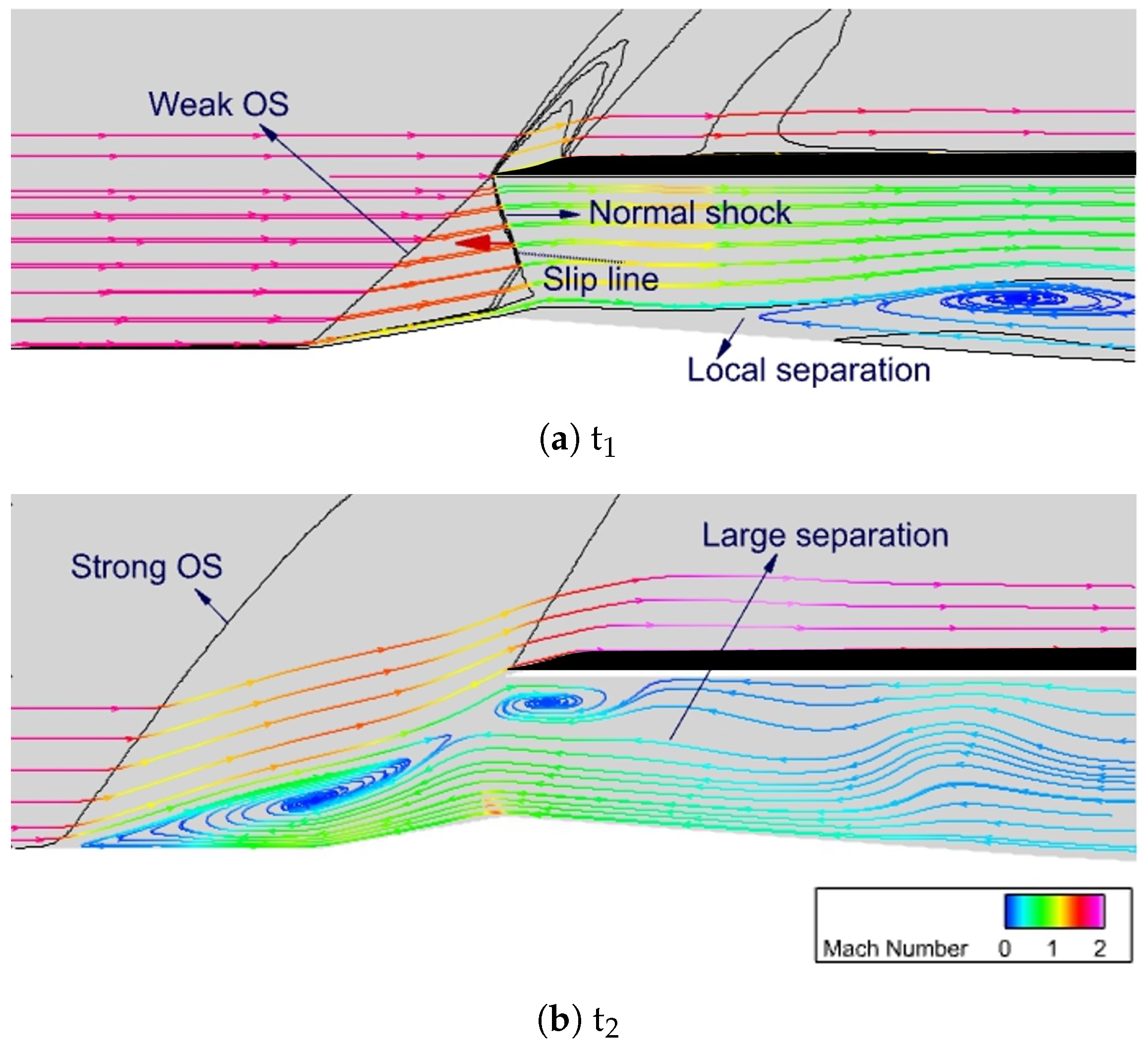
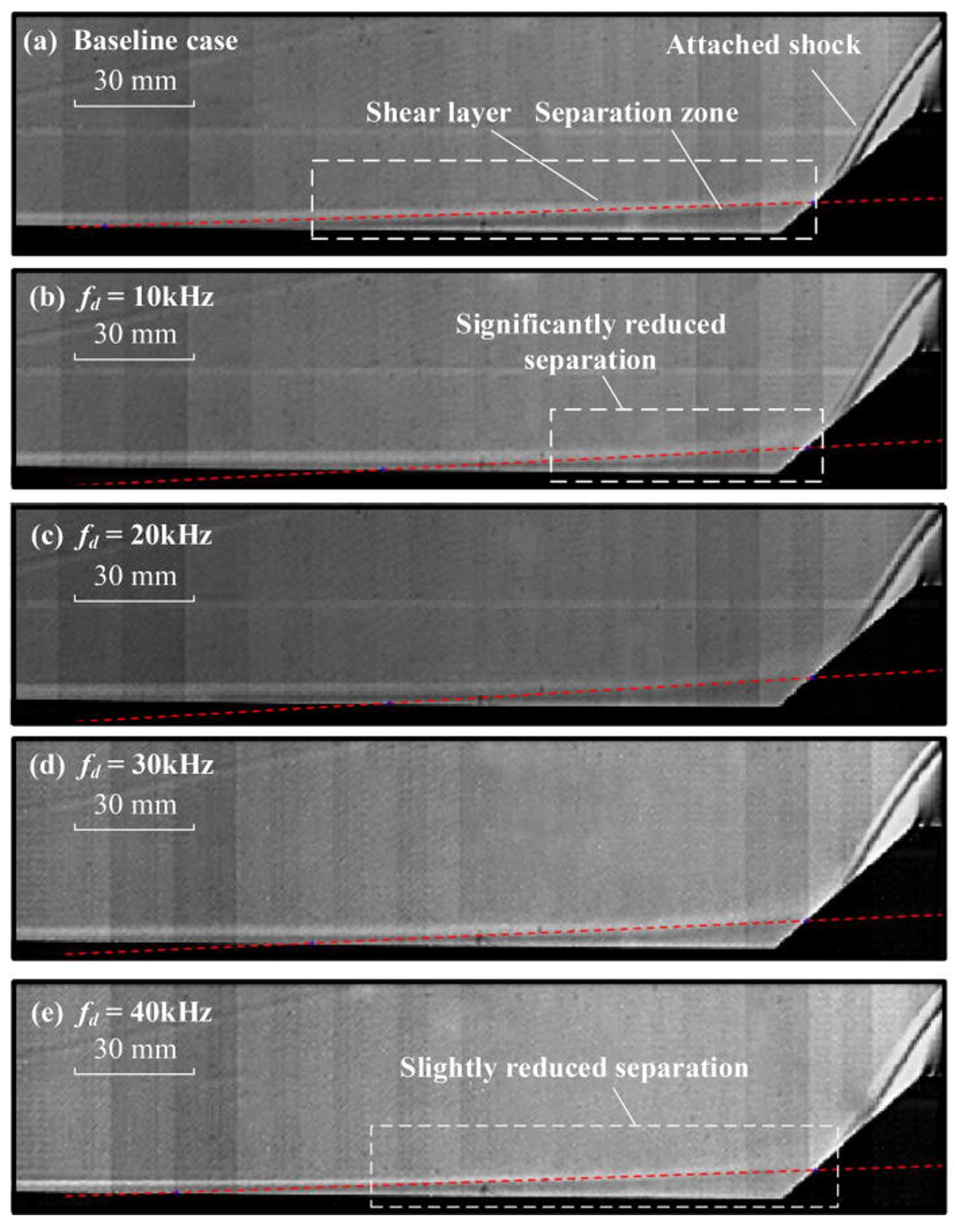
Similarly, Soltani et al. [37] explained the sequence of one buzz cycle, illustrating that a strong shockwave boundary layer interaction (SBLI) results in large flow separation where the shear layer of the separation zone collides with the cowl lip’s inner surface and triggers Ferri instabilities, suggesting that Ferri and Dailey instabilities can coexist (see Figure 6). The coexistence of little and big buzz was previously noted by Soltani and Farahani [62], who noticed highly energetic oscillation at M = 2.2 for a moderate mass flow, and named it “added buzz”.
This characteristic was also confirmed by Chen et al. [63], where the coexistence of little and big buzz at a high TR in the range of 70–80% was also found; this phase was named “mixed buzz”. The authors also illustrate that the shear layer related to little buzz may have two possible origins, either from the ramp–normal shock interaction, or from the separated–normal shock interaction. The little buzz shown in the current study, showing similar behavior to previous studies [37,43], was found to be generated by the interaction between the normal shock and the separated boundary layer on the compression surface, with low-frequency fluctuations. However, the authors suggested that this phenomenon relates to the Dailey and not the Ferri instability.
It appears that some studies distinguish between little and big buzz in terms of amplification of frequency or amplitude, while others focus on the triggering mechanism. Chen et al. [63] also suggested that little buzz should not be distinguished only by the presence of the shear layer, since it has been observed that little and big buzz share a common origin, but the differences lie in the amplification of the perturbations in frequency and amplitude.
The following work by Chen et al [64] analyzed “mixed buzz” and suggested that big buzz is not self-sustained at the beginning and transitions towards little buzz. This transitioning process brings up several oscillation cycles with moderate amplitude, defined as “medium buzz”. In contrast to big buzz, “medium buzz” is confined to a narrow region near the ramp surface. A closer inspection indicates a blocking effect of the backflow, causing the upper shear layer behind the bow shock to push downward, reduce the flow area below, and restrain the expanding separation bubble. Therefore, “medium buzz” is characterized by the terminal shock motion and the varying cowl-side backflow [65]. The authors conclude that the buzz flow diversity originates from the vertical division of the shear layer originating from the SBLI and may potentially complicate the disturbance feedback when buzz takes place.
Fisher [33] suggested that little buzz is associated with lower amplitude oscillations compared to big buzz, but both phenomena exhibit similar frequencies. However, recent studies have demonstrated that little and big buzz have different couplings in terms of frequency and amplitude. The diversities of the two trigger mechanisms of the buzz phenomenon and the associated dominant frequencies are very clear in the existing literature. Studies generally agree that the amplitude of little buzz is of smaller or similar magnitude to big buzz, but the frequency shows a more diverse behavior.
The different explanations of the buzz cycle and oscillatory patterns observed during the buzz phenomenon are equally important. While Soltani and Younsi [37] observe two phases during the buzz cycle, the “subcritical” and “supercritical” operations, Trapier et al. [44] refer to three phases, namely the “subcritical”, “secondary oscillation”, and “supercritical”. Nakayama et al. [66], on the other hand, mentioned two phases, but classified them as “supercritical” and “pseudo subcritical”. Lee and Jeung [67] referred to three phases during a buzz cycle, namely “subcritical”, “reattachment”, and “restart”. The operation modes of buzz were also recorded as “intermittent” and “continuous” buzz, while Fisher [33] distinguished the oscillatory patterns into “little buzz” and “big buzz”. More recently, Chen et al. [63] observed the so-called “mixed buzz”, while Soltani and Farahani [62] referred to the highly energetic oscillatory pattern as “added buzz”. When the effect of the boundary layer bleed was studied by Chen et al. [68], the authors reported a “mild buzz”. Further discussion on the boundary layer bleed is found in Section 4.
In the literature, it is evident that the buzz phenomenon exhibits characteristics that vary on a case-by-case basis. There could be several factors that could lead to these discrepancies, one obvious factor being the geometry configuration design. Grossman and Bruce [69,70] have shown that changing the aspect ratio (AR) in rectangular ducts can influence the three-dimensionality of the flow field. In more detail, by increasing the AR, the topology changes, which in turn leads to an increase in the extent of the shock-induced boundary layer separation. The separation grows proportionally in the streamwise and stream-normal directions. The geometry design can have a major impact on the flow topology and overall SBLI behavior. This effect may become significant in an unsteady environment when the shock-induced separation generates a shock oscillation. The interaction of SBL can play a significant role in establishing the buzz fluctuation [37]. A different cross-sectional shape can also affect the flow behavior as it determines the boundary layer growth along the walls, which in turn influence the total pressure distribution. For instance, a square-to-circular isolator is observed to have a smaller separation region influenced by corner vortices compared to a square isolator. Additionally, the flow separation region appears wider and shorter, even though both isolators exhibit the same total pressure recovery [71]. Table 1 summarizes several studies investigating intake buzz, and it is observed that rectangular intakes, having no corner curvature, exhibit low dominant frequency and high-amplitude oscillations during big buzz. It is not suggested that the geometry configuration is the reason for the discrepancies but could potentially be a factor that requires further investigation. Moreover, the recording of the peak frequency of the oscillation is very sensitive with regard to its streamwise position, and comparing results between studies is difficult, considering that the exact location of the frequency transducer signal may differ. The Strouhal number of each case has been computed based on the available data in each study.
Since it has been established that supersonic buzz is associated with the acoustic resonance, we can introduce the Strouhal number when analyzing unsteady oscillating flow phenomena, as it describes the flow oscillation mechanism. The Strouhal number (fL/U ), where L is the intake duct length, f is the peak frequency, and U is the freestream velocity, is known to be affected by the freestream Mach number, Reynolds Number, turbulent intensity, angle of attack, radius of curvature in corners, and aspect ratio. Thus, the frequency of the system may also indirectly be influenced by these factors.
It is important to mention that while the supersonic intake buzz frequency can be predicted using analytical solutions from the acoustic theory, this is not the case for hypersonic intakes [72]. The flow phenomena of a hypersonic intake are more complex and differ from the supersonic intakes. This is attributed to the fact that the flow captured by the intake can be primarily supersonic and a temporary supersonic region can exist in the intake throat, which blocks the upstream propagation of the acoustic waves. As a result, the oscillation frequency cannot be predicted using traditional acoustic theory, as previously done for supersonic intakes [11,59,60]. The separation can act as a resonance source since it induces other flow instabilities leading to intermittent supersonic flows that can travel downstream of the intake. Tan et al. [73,74] reported multiple resonance frequency sources and proposed a method to estimate the dominant frequencies incorporating these resonance sources. Similarly, Sekar et al. [75] formulated a semi-empirical relationship to predict the buzzing frequency for any given operating condition using existing experimental results in the open literature. Due to other effects, such as aspect ratio, corner flow separation, and flow leakage, the calculated frequency from the current two-dimensional numerical analysis deviates slightly from the obtained semi-empirical equation.
As mentioned by Chang et al. [72], the flow behavior, the mechanisms of the buzz phenomenon, the oscillatory patterns, and the overall flow behavior in a hypersonic intake are different compared to a supersonic intake. A hypersonic intake may unstart due to over-contraction [11], resulting from a large flow separation, intake design, the variation of flight conditions [76], or high back pressure, which cannot be sustained by the intake [12]. During unstart, the oscillations are divided into three parts, (a) the mass filling up, (b) the shock system disgorging and swallowing, and (c) the near-throat flow pattern establishing and back pressure propagating [74]. A comprehensive review on the unstart operation arising from flow choking in hypersonic intakes was presented by Im and Do [15] in 2018.
In an unstarted hypersonic intake, various oscillatory patterns exist, including, but not limited to, little and big buzz. Wagner et al. [11] experimentally studied an intake at a Mach number of 5 and identified three types of oscillations: a high-amplitude and frequency oscillation, a low amplitude and frequency oscillation, and a non-oscillatory unstarted flow characterized by low-pressure fluctuations. Chang et al. [60] observed two types of oscillations, with one incorporating both little and big buzz, where strong oscillations are followed by weak oscillations and then a non-oscillatory pattern.
Zhang et al. [77] evaluated a hypersonic intake at Mach 6 with side compression and observed violent big buzz oscillations, accompanied by secondary high-frequency oscillations during the low-pressure wave propagation stage. It is inferred that these secondary oscillations result from acoustic resonance developed between the high-density air and the isolator or duct exit.
More recently, Xu et al. [78] experimentally studied the starting hysteresis phenomenon with varied angles of attack on an axisymmetric intake with an operating Mach number of 5. During the restarting process, the angle of attack began to decrease from 12 to 0 while the intake was unstarted, and two kinds of fluctuation patterns were observed. As AOA decreased from 3.2 to 1.0 , the flow exhibited low-frequency fluctuations, with a mixed oscillating pattern of high and low-amplitude oscillations. While high-amplitude oscillations had equal durations, low-amplitude oscillations were random. Hence, this oscillating pattern is named the intermittent high-amplitude oscillation. When AOA further decreased from 1.0 to 0.3 , the duct oscillations became periodic.
High-speed intakes have a risk of unstarting when the mass flow entering the intake encounters a sudden reduction [12]. When the terminal shock appears at the throat, the intake is said to operate at a critical condition and any further reduction to the mass flow rate would shift the shock system upstream and force the intake to operate in a subcritical condition. At this stage, the pressure recovery of the intake can be significantly penalized and the rise in back pressure could cause the intake to choke, forming upstream propagating disturbances, and leading to pressure fluctuations. This can lead to reduction in the thrust as well as difficulties in combustion and mechanical integrity [58].
Table 1. Experimental (E) and numerical (N) supersonic/hypersonic intake buzz studies.
ReferenceMethod (E/N)Intake GeometryCompression SystemMachBuzz Type DefinitionDominant Frequency (Hz)Buzz Cycle (s)Strouhal No. St = fL/U
Trapier et al. [48]E2DMixed1.8, 2, 3Ferri
(Low amplitude)
120–1400.007–0.008N/A
Dailey
(High amplitude)
12–200.08–1
Nagashima et al. [50]EA/S * External2Frequency-Based1000.01N/A
(Similar amplitude)3600.0027
Fisher [33]ERectangular (Build A)External1.9Ferri (Low amplitude)45N/AN/A
Dailey (High amplitude)48
Chima [79]NA/SExternal1.66Dailey (High amplitude)16.90.0590.089
Herrmann et al. [58]ERectangularExternal2.5Dailey
(High amplitude)
43N/A0.085
Trapier et al. [44]NRectangularMixed1.8Dailey (High amplitude)17≈0.0570.064
Soltani and Younsi [37]EA/SMixed2Dailey960.01N/A
Chang et al. [60]E2DMixed5Dailey
(Weak cycle = low
Strong cycle = high)
110Weak = 0.011 Strong = 0.017N/A
Nishizawa et al. [51]N2DExternal1.64Dailey640N/A0.078
Hong and Kim [43]NA/SExternal2Dailey367N/A0.35
Soltani, Farahani [62]EA/SExternal2.5Ferri
(Low amplitude)
1250.0072N/A
Dailey (High amplitude)1380.012
Chen et al. [63]ERectangularExternal2Dailey179.70.00560.094
Grenson and Benedine [80]E and NRectangularExternal1.8Amplitude Based
(Low amplitude)
E = 107
N = 750
0.00160.09
(High amplitude)E = 83
N = 550
0.00180.069
Abedi et al. [38]NA/SMixed2Dailey (High amplitude)112.50.009N/A
Zhu et al. [81]NA/SExternal2Frequency-based (High amplitude)120N/A0.116
(Low amplitude)360 0.35
* A/S: axisymmetric
During intake buzz, depending on the trigger of the instability, the pressure experiences low or high fluctuations. It is understood that low amplitude pressure fluctuations relate to the Ferri instability or “little buzz” with a separation bubble on the inner cowl wall shrinking and expanding periodically; Dailey-instability, known as “big buzz”, experiences larger pressure fluctuations with the shock system being circularly destroyed and re-established [82]. Trapier et al. [49] demonstrated the time history of the energy levels experienced in the diffuser during little and big buzz at M = 2. It was revealed that the shock motion had a noticeably smaller amplitude during little buzz than big buzz. It is evident that big buzz is progressively gaining energy until the energy switches from little to big buzz, where the total energy remains constant. More importantly, it is revealed that big buzz exists even during little buzz, but its presence, at that instance, is overshadowed by little buzz. This can suggest that the big buzz mechanism may also be linked to acoustics.
As previously mentioned, the geometric configuration influences the unsteady flow phenomena in the intake. Fisher [33] examined different cowl tip positions and reported that with the cowl tip position reducing in vertical height, the amplitude of little buzz reduces until it is fully mitigated. It is plausible that by lowering the cowl tip position, the focal point of the intersection between the oblique and normal shock is no longer ahead of the cowl lip. Consequently the induced flow separation is absent from the inner cowl surface, as the resulting vortex sheet can no longer collide with the inner cowl surface.
Generally, studies record an increasing amplitude of pressure fluctuations with a reduction of mass flow [33,83]. This is because, at higher throttle ratios, big buzz dominates over little buzz. However, there are a few reported cases where the amplitude between little and big buzz is of similar magnitude [43,50,68]. Table 1 includes details of pressure fluctuation amplitude in several studies. It is difficult to directly compare the amplitude of the fluctuations between the studies, given that the positions of the pressure transducer signals may differ, and the amplitude recording can differ as they are interchangeably expressed in terms of static pressure, non-dimensional total pressure, or power spectra density (PSD). Furthermore, noise in the signal can complicate the detection of an increase in the amplitude of the frequency [49]. Also, a detailed examination of each study’s error and uncertainty in pressure recordings would be required for a fair comparison; however, this is beyond the scope of this paper.
Whilst most studies record the pressure fluctuations at the buzz location, other studies have recorded pressure readings across the entire length of an intake model. Lu et al. [40] noticed that the pressure fluctuated in similar high intensities at different locations within the center body region, while the pressure within the plenum chamber demonstrated a declining trend. The pressure in the plenum chamber increased when the shock accelerated back toward the cowl lip. Similarly, Yeom et al. [84] examined the effect of buzz on flame oscillation, at M = 2.1, using a ramjet engine model, extending from the leading edge of the inlet to the exhaust nozzle. The authors recorded pressure readings throughout the entire length of the model. The ramp surface experienced the largest pressure fluctuations, and the amplitude gradually decreased through the flow path, due to the dissipation of fluctuation, up until the combustor exit, where it suddenly increased. It was explained that this was due to the vortex-induced acoustic oscillation at the contraction of the nozzle area. It should be noted that the pressure immediately downstream of the terminal shock and throughout the diffuser seemed to oscillate at the same frequency of 294 Hz. Kwak et al. [85] also recorded pressure fluctuations across the entire length model. In contrast, the signals near the inlet throat and the diffuser and plenum chamber exhibited the same frequency, but the amplitude within the plenum chamber was higher. Also, the time histories of pressure at the ramp exhibited more of a square wave periodic oscillation with intermittent behaviors, while the oscillations within the diffuser and plenum chamber were periodic complex waves. The behavior of the pressure fluctuations on the ramp can be justified by the constant shock movement. In fact, there is a strong correlation between the shock oscillation and pressure fluctuations, as demonstrated by Wang et al. [82], as the pressure transducers on the compression ramp experience a phase difference when the shock train propagates upstream.
More recently, Grenson and Beneddine [80] showed that pressure varies periodically across the duct, but the fluctuations are not in-phase between the fore and rear part of the duct during little buzz, as it would be expected for the fundamental duct acoustic mode (n = 0). While many studies show how the observed frequency of little buzz is closely related to the fundamental frequency of the acoustic mode, Grenson and Benedine [86] have observed little buzz frequency to be significantly lower. They associated the shock oscillation of the terminal shock with an expansion wave propagating in the subsonic diffuser at a higher velocity than the upstream propagating compression wave, resulting in a longer cycle and lower buzz frequency. In a similar manner, Candon et al. [87] explained the discrepancy between the observed and fundamental frequency to be due to the terminal shock acting as an acoustic buffer for upstream traveling waves. It is possible for multiple waves to exist within the diffuser, and only when they coalesce far upstream do they cause a strong shock oscillation. This could also explain, in their case, the single, double, and triple peaks of pressure events captured just upstream of the throat.

2.2. Effect of Operating Conditions on Intake Unsteadiness

While the initial focus was on understanding the origin and triggering mechanisms of intake buzz, later investigations shifted to studying the influence of operating conditions on the buzz phenomenon. During a typical flight profile, changes in upstream flow conditions are expected, so the air intake should be capable of operating under a wide range of flight regimes and angles of attack, as well as at both design and off-design conditions. Several studies have investigated the variations in upstream flow conditions, such as the Mach number and angle of attack, and their influence on intake buzz, both of which are summarized in this section, respectively.

2.2.1. Effect of Mach Number

An important characteristic of supersonic and hypersonic intakes, as highlighted by both experimental and numerical work, is that the flow field and the achievement of efficient intake performance are considerably dependent on the freestream Mach number. The performance characteristics of an air intake at higher flow Mach numbers are more crucial, as the stability of the intake is decreased [88]. To gain a better understanding of the buzz instability, the research community investigated the effects of different freestream conditions.
Soltani et al. [36] extensively investigated buzz instability under a range of freestream conditions, M = 1.8–2.5, using an axisymmetric external compression intake. The study clearly shows that the Mach number affects the position of the normal shock, and depending on the freestream Mach number, the buzz may occur at higher values of the mass flow rate [89].
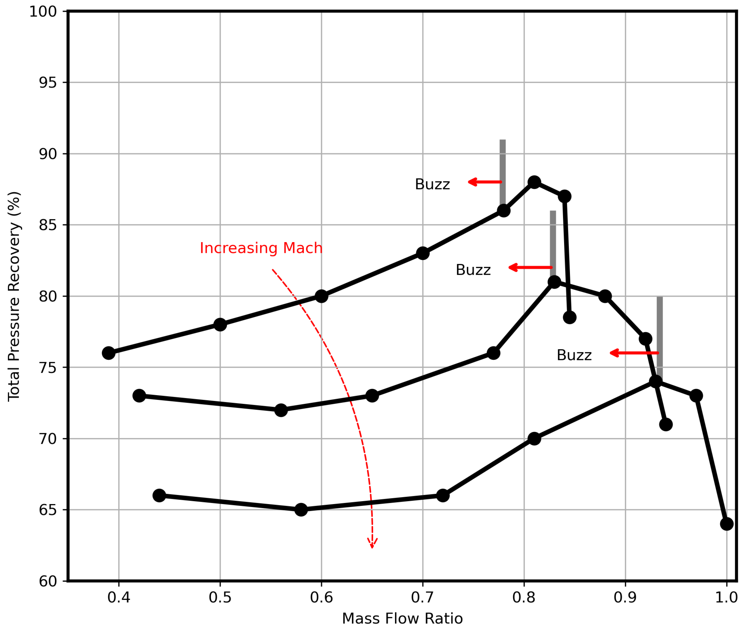
With an increase in the freestream Mach number, the normal shock is strengthened, which promotes flow separation over the spike. Thus, the stability margin is affected since the intake buzz phenomenon is initiated earlier at higher mass flow rates and, therefore, at different operating conditions [36,37,62,90,91]. This is clearly depicted in Figure 7. With an increase in the freestream Mach number, higher values of the exit blockage ratio are required to expel the normal shock out of the intake. However, high EBR values have a negative effect on the intake mass flow rate since more mass flow spillage occurs.
At low Mach numbers of 1.8–2.2, the variation in the shock movement amplitude is subtle, while at M = 2.5, the flow exhibits a large shock movement amplitude with a larger instability zone. The frequency of oscillation is fairly independent of the Mach number [62] with a somewhat decreasing pattern [36,37,58].
While the stability margin of the intake is adversely affected by the increase in the flow Mach number, the intake flow distortion also increases (the reader is directed to Figure 12 of Ref. [90]). The flow distortion is relatively low when the intake operates under subcritical conditions (EBR > 60–65%), but this is not the case in supercritical conditions. This is due to the interaction between a strong, normal shock and the boundary layer, generating significant flow separation, and leading to higher intake flow distortion. The normal shock–boundary layer interactions are even stronger at higher Mach numbers, resulting in greater flow distortion experienced by the intake. Consequently, the total pressure recovery decreases.
Evidently, the Mach number influences the duration of the buzz cycle, as noted by Soltani et al. [62], who observed that, for a constant angle of attack of 6 , increasing the Mach number from 2 to 2.5 leads to a slightly longer buzz cycle period and growth to the asymmetry of the shock system. Of course, the mass flow rate between the two cases differs for the reasons explained before, so the M = 2.5 case is at a higher mass flow rate. James et al. [92] investigated the flow characteristics of a 2D axisymmetric mixed-compression intake at three different Mach numbers of 2.0, 3.0, and 5.0. The authors observed that with an increasing Mach number, the number and size of separation zones increase as the flow velocity through the duct is increased. The multiple separation zones are the reason why the oscillation frequency is not related to the 1D acoustic theory. The dominant frequency originates closer to the exit of the intake and decreases with the increasing Mach number. The study shows that for a higher freestream Mach number, the upstream propagation time of the separated zone is higher compared to the downstream movement. The study similarly revealed that the period of the buzz cycle is extended with the increasing Mach number, and this can be related to the frequency characteristics.
Studies relating to the effect of upstream flow conditions in hypersonic intakes have mainly focused on the influence of the Mach number on the intake starting performance. For a given intake with a fixed geometric configuration, there is a certain contraction ratio. An intake is designed to operate on a range of Mach numbers, specified by the Kantrowitz and isentropic limit [93]. If the intake operates on a lower Mach number, the intake will unstart [94], and the total pressure recovery and the mass flow captured will be reduced [95]. At an operating Mach number higher than the design value, several studies [75,96,97,98] have identified that a Mach reflection causes the forward shock propagation and a shock detachment from the cowl lip, referred to as “local unstart”.

2.2.2. Effect of Angle of Attack

When an aircraft undergoes a maneuver, the change in the angle of attack can have a significant effect on the flow behavior in supersonic and hypersonic intakes. While studies on supersonic intakes have investigated the effect of the angle of attack on buzz characteristics, research on hypersonic intake studies has focused on the starting performance of the intake.
Lee and Jeung [67] investigated the effect of angle of the attack at 2 and 4 , on an axisymmetric external compression intake with an inflow freestream Mach number of 2.5. The study demonstrates that the location of the normal shock shifts upstream with an increasing angle of attack, but the shock movement on the leeward side is larger, with a greater separation size compared to the windward side, causing the buzz to become asymmetric. In addition, the leeward and windward sides experience different shock displacement and buzz frequency for non-zero angles of attack [89].
Soltani and Farahani [62,89,99] looked more closely into the effects of the angle of attack on the buzz initiation and characteristics, and reported that for a constant Mach number of 2, increasing the angle of attack decreases the intake performance and the stability margin, causing an earlier initiation of the intake buzz. The combination of the angle of attack and mass flow rate seemed important since different characteristics were observed. While initial results indicated that at a low mass flow, the buzz frequency experiences only minor changes with the angle of attack [62], further investigation revealed that for low and moderate mass flow rates and an AOA < 6 , the buzz frequency remains nearly unchanged throughout the entire intake duct. However, at a low mass flow rate with an AOA = 10 , the front portion of the intake experiences a high-frequency buzz, and the downstream portion of the diffuser has a buzz frequency equivalent to the one observed in the lower angle of attack cases (Figure 13 of [99]). It is suggested that the diffuser damps the high-frequency oscillation. It should be mentioned that the effect of the angle of attack depends on the freestream Mach number. While at Mach numbers ranging from 1.8 to 2.2, the buzz amplitude shows only small variations with changes in the angle of attack, at Mach 2.5, the amplitude demonstrates different values for each angle of attack, and these variations are distinct for different mass flow rates [62].
Similarly to the work of Soltani and Farahani [62], Namkoung et al. [100] noticed that buzz frequency does not change dramatically with AOA for a constant throttle ratio of 0, but the shock structure varies abruptly, in the sense that it becomes asymmetric. Looking at the induced distortion from the asymmetry of the flow, the study shows that, as the angle of attack increases from 3 to 10 , the shock structure and flow physics appear asymmetric. This causes an almost proportional increase to the averaged distortion coefficient, while simultaneously displaying a large incremental variation in the maximum distortion coefficient. Moreover, Boychev et al. [101] numerically examined the performances of three intake configurations with a fore-body intake geometry at a freestream Mach number of 2. The study indicates that, at an incidence angle of 0 , the square-shaped intake exhibited the least distorted flow and total pressure recovery at the engine face, in contrast to intake configurations resembling kidney shapes and rounded corners. However, at higher incidence angles, the flow distortion and total pressure recovery are less sensitive to the intake geometry.
As mentioned before, the effect of the angle of attack with a varying mass flow rate exhibits different characteristics. More specifically, Farahani and Jaberi [89] observed that for a Mach number M = 2.0, within the AOA range of 0–3 and 6–10 , the buzz frequency displays a similar decreasing pattern. However, between the angles of 3 and 6 , and at a mass flow ratio of 0.26, strangely, the buzz frequency exhibits a large jump (see Figure 9 of Ref. [89]). This behavior is not observed in other values of mass flow rate or other Mach number cases. Moreover, for M = 2.2, when the angle of attack increases from 3 to 6 , the period of the buzz cycle doubles.
Herrmann [58,102,103] extensively studied the intake performances at a design Mach number of 3.0, with an angle of attack range of 0–30 . While the captured mass flow decreases with an increasing angle of attack due to the reduced effective area seen by the incident flow, the greatest mass flow loss occurs at AOA 18 . This is due to the formation of a shock system on the windward side of the cone blocking the inlet’s entrance, causing flow spillage, and the formation of vortex systems from the apex of the cone at the leeward side, which increases in complexity at higher angles as the vortices move closer to the center of the leeward side. The flow field was visualized using the oil flow method, and sharp lines appeared on the cone’s surface, for AOA = 25 and AOA = 18 , which could be an indication of embedded shocks or induced shocks from the vortices. Further investigation revealed a subtle distinction of separation and reattachment lines present on the leeward side, suggesting a complex vortex system. These flow effects appeared to be interfering with the ramjet’s performance. In contrast to positive angles, at negative angles of attack, the characteristics of the intake developed differently in the sense that—with the increasing negative angle—the mass flow and pressure recovery faced a continuous decrease. At higher negative angles, the vortices developed on the leeward side and their intensity grew and shifted toward the center of the leeward side, exhibiting high-pressure losses.
For hypersonic intakes, like the Mach number, the angle of attack can affect the starting performance [94]. With a positive angle of attack, the flow has a stronger compression, while the effective incoming Mach number decreases, thus the capabilities of the unstart/self-start of the intake decline [104]. Liu and Zhang [76,105] numerically and experimentally investigated the starting characteristic with the angle of attack for a side-walled compression intake and a 2D hypersonic intake. By comparing the steady-state and unsteady-state cases, it is clear that the isolator is where the difference in pressure recovery occurs. The results show that with an increasing oscillatory frequency, the unstart value of the AOA increased, while the restarting value of the AOA decreased. In evaluating the intake’s ability to restart, the intake restarted during the rise of AOA from 0 to −25 . However, the intake was unable to restart when the AOA decreased from 25 to 0 , as the separation bubble was unresponsive to the change in AOA in time. Similarly, a steady-state numerical study on a wave-catcher intake showed that the intake experienced starting hysteresis, where a start-unstart-restart process occurred with increasing negative AOA. But at positive angles, the intake remained unstarted [106]. The range of AOA between the increasing and decreasing processes was different, though. For instance, the AOA increased from 0 to 2 , while for the decreasing process, the angles ranged from 0 to −8 . Therefore, further investigation with a larger range of positive angles is required to reach a fair conclusion.
A recent experimental study [78] analyzed the starting hysteresis caused by the angle of attack on a hypersonic axisymmetric intake at a Mach number of 5.0. According to the starting theory, there are three different regions of the intake state that appear, depending on the AOA: (a) the start region (AOA < 0.3 ), (b) the double-solution region (0.3 < AOA < 8.4 ), and (c) the unstart region (AOA > 8.4 ). When the intake is unstarted, the flow across the duct exhibits unsteady behavior. An investigation into the frequency characteristics—when the intake is at an AOA of 12 —illustrates that the propagation of the low-amplitude fluctuation is limited to the throat. During the restarting process, big buzz emerges, and as AOA decreases from 3.2 to 0.3 , the duct experiences pressure fluctuations and a mixed oscillation pattern with high and low-amplitude oscillations.
It is obvious that under different flight profiles, the flow can become highly unsteady and distorted, and while some effects can be reduced with considerate designs of the intake, other means are required to eliminate or delay the undesired flow behavior and widen the intake operability range. In recent years, the scientific community has focused more on analyzing the flow behavior during intake buzz, and studying different approaches to mitigate excessive flow unsteadiness associated with undesired instabilities of the air induction and propulsion systems.

2.3. Suppression of Intake Buzz and Unstart Mode

An essential part of the intake design process involves the suppression and elimination of instabilities, such as intake buzz and unstart encountered at off-design conditions. To this end, numerous techniques were developed to control flow separation, such as the passive or active boundary layer bleed, vortex generators, mass injection, and energy deposition. A comprehensive review article published by Younsi et al. [107] in 2018 summarizes the development of boundary layer suction in high-speed air intakes and the effects of various bleed parameters on intake performance and stability. To avoid repetition, studies focusing on the suppression of buzz through the use of boundary layer bleed will be reviewed, considering publications from 2018 onward. This section covers a review of all the potential techniques mentioned above, aiming to suppress intake instabilities.

2.3.1. Boundary Layer Bleed

The performance of the intake is compromised by the boundary layer separation. If the separation of the flow becomes significant enough to choke the intake and induce fluctuations in the shock system, the resulting flow dynamics can diminish engine thrust, lead to combustion shutdown, and potentially cause structural issues [62]. Boundary layer bleeding is the most common method used to remove the low-momentum portion of the boundary layer and prevent flow separation arising from the SBLI in supersonic intakes. There are two types of bleed systems used: porous and slot. Generally, the slotted bleed is used when the region of separation is known, and a large mass is required to be bled out, while the porous bleed is used when the boundary layer separation can vary with time, or the exact region of separation is unknown, and a small uniform air mass is required to be bled out [107].
It is evident that a slot boundary layer bleed can significantly improve the intake performance and stability by preventing flow separation on the compression surface [58,91,108], especially when the shock train is close to the slot region [61,109]. Sethuraman et al. [109] managed to reduce the shock oscillation by 50% with suction control, and reduced the oscillating frequency of the first shock by about 5 Hz, illustrating the effectiveness of the suction control when the shock train appears closer to the slot region [110]. However, with various back pressures, the location of the normal shock varies, and the slotted bleed can be less effective. To overcome this, the porous bleed is introduced since it can be applied across a larger surface area. Maadi and Younsi [111] conducted an experimental study on a mixed-compression intake for M = 1.8–2.2, to compare the performance of slot and porous bleed systems. For the case of M = 2.0, the porous bleed can cause higher total pressure recoveries and lower flow distortion. The slotted bleed on the other hand is more effective at delaying the onset of buzz with a smaller amplitude of oscillations since the slot bleed allows for a larger mass flow to be expelled out. The porous bleed is more effective in supercritical operating conditions since more oblique shockwaves are generated within the diffuser before the terminal shock.
While the porous bleed method is quite simple, the design of such a method has become a challenge in numerical simulations, since the complex geometry can be quite computationally costly. Therefore, some researchers have followed a different approach, one where a bleed model is applied as a boundary condition at the wall, eliminating the meshing process of the bleed holes. Slater and Saunders [112] investigated a porous bleed system on a supersonic intake and proposed a porous boundary condition for use in steady-state numerical simulations [113] (see Table 2). Choe et al. [114] attempted to improve the Slater boundary condition model by introducing the effect of local flow expansion and incorporating porosity variation effects on the model, showing a more accurate representation of the bleed rate. Giehler et al. [115] conducted a comparison study of seven available porous bleed models based on a three-dimensional reference simulation. The study revealed that all porous models were limited in defining the uniform blowing and suction. As a result, the wall shear stress was significantly overestimated, leading to a flow highly resistant to adverse pressure gradients induced by shock. In a recent study conducted by Wang et al. [116], the authors developed a simplified method for modeling bleed holes in supersonic intakes, showing good agreement with experimental data. This method first computes the location of the barrier shock within the bleed hole, considering the static pressure and Mach number upstream of the bleed hole, as well as the plenum pressure. Then, the shape of the hole is determined by identifying the grid points connected to the bleed holes, followed by calculating the bleed mass flow rate in the same fashion, as proposed by Slater [113].
While the type of bleed has some effect, the geometric parameters of the bleed system, such as entrance area, position, slant angle, and bleed mass flow rate, can have a significant impact on the flow characteristics. Soltani et al. [61,90,117] investigated the effect of the slot bleed and its parameters on the intake performance across design and off-design conditions. Younsi [107] experimentally investigated the effects of several bleed parameters, such as slant angle, entrance area, and bleed position for both porous and slotted bleed systems. Moving the bleed system forward at the tip of the cone is ineffective at improving the intake stability margin, since the flow separation that triggers the shock oscillations is further downstream. The bleed positioned in the middle of the spike is best for stabilizing the intake at subcritical conditions. While it produces a buzz frequency that is almost nine times the frequency of the no-bleed case, the amplitude of oscillations is much smaller compared to the no-bleed case. The changes in slant angle and entrance area have negligible effects on delaying the onset buzz. Apart from geometric parameters, the bleed mass flow rate can alter the flow behavior and delay the unsteady phenomena. While it is difficult to eliminate the flow unsteadiness completely, active and passive boundary layer bleed systems can delay the intake unstart. However, the effectiveness of suction control, depends on the suction rate and suction timing [118].
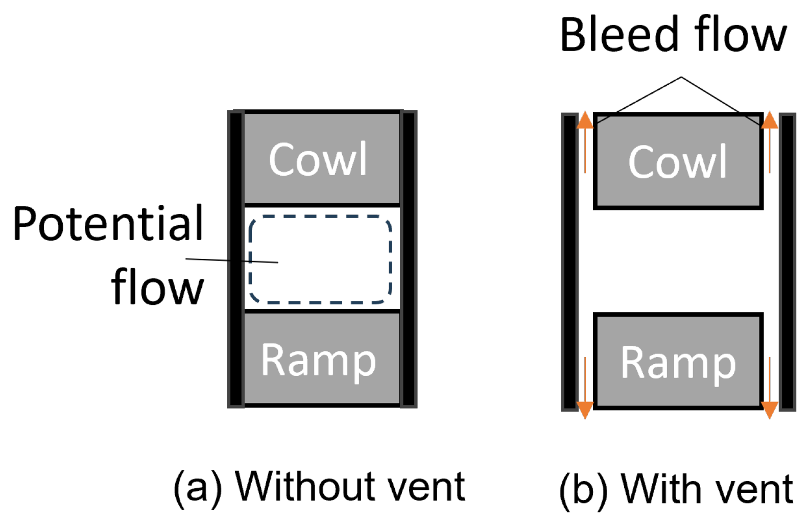
More recently, another passive bleed was examined; introducing the natural ventilation for passive bleeding of the boundary layer. This allows air to be bled along the sides of the ramp and cowl by splitting the side plates and leaving vent gaps between the ramp and the cowl, essentially ventilating the intake (see Figure 8). Implementing small ventilation gaps along the intake, the internal viscous flow is bypassed to ambient conditions, improving the air flowing toward the engine face. The present technique was employed by Suryanarayana et al. [119,120] on a two-dimensional intake model with a Mach number range of 1.8–3.0. Their study demonstrates the successful postponement of the buzz phenomena under both design and off-design conditions, accompanied by a substantial improvement in total pressure recovery. Even though it fails to eliminate the intake buzz, the intensity can be lower compared to an unvented intake. The bleed gap can also significantly alter the flow characteristics. The study shows that at critical and subcritical operations, all bleed gaps (0.5 mm, 1 mm, 1.6 mm) produce a high-pressure coefficient, as the bow wave at the cowl lip is alleviated. But a bleed gap larger than 1.6 mm can lead to the loss of potential flow, thus degrading the intake performance. To investigate the effect of the side wall gap on the intake starting ability, Ogura et al. [121] showed that using a side gap only on the third ramp of a three-compression ramp intake can widen the starting range since it slows down the terminal shock movement by reducing the back pressure. Adding a positive angle of attack has a negligible difference to the starting range compared to an AOA = 0 .
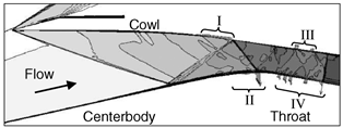
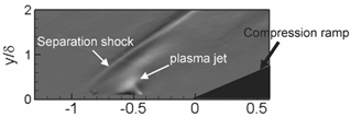
Research studies have shown that a single bleed system alleviating the flow separation alone is not effective at completely eliminating the intake buzz that operates across a range of operating conditions. Apart from the change in location of the shock train on a range of operating conditions that changes the boundary layer bleed’s effectiveness, another reason is the mismatch of the air supply and demand that can trigger a global collapse of the flow field by a fast pressure build-up [68]. To address the initial issue, the implementation of the bleed system is recommended in conjunction with other flow control techniques, strategically applied across various locations within the intake. This combined approach is anticipated to yield enhanced effectiveness. Other studies have combined the bleed system with other flow control methods, such as vortex generators [122], plasma injection [123], mesoflap [124] and cavity [125]. For the second problem, recent studies [126,127,128,129] have examined a new bleed system design, mostly in steady-state conditions, consisting of multiple parallel slots. With a multi-slotted bleed system located upstream of the intake throat, sufficient flow spillage occurs that discharges the excessive captured airflow. Chen et al. [68] numerically and experimentally investigated a multi-slot bleed system in unsteady operating conditions for an external compression intake. The results show that with the implementation of the bleed system, global instability was never triggered, and the intensity of the buzz was considerably lower. Interestingly, the flow instability at a late subcritical stage with the bleed system showed the formation of a mild buzz regime, which was neither related to the Ferri nor the Dailey instability; in fact, the authors suggest that the triggering mechanism of buzz may not be limited to only those two sources.

2.3.2. Passive Vortex Generators

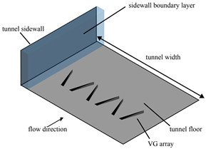
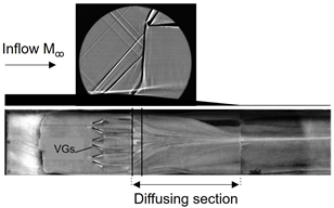
Vortex generators (VGs) have been widely used across the industry to delay or prevent shock-induced separations, and the working principle is well understood. Traditional VGs are usually placed ahead of a region experiencing an adverse pressure gradient, to create a vortex that draws air into a low-momentum boundary layer, making it less susceptible to separate. Micro-VGs are a more recent development; they have a similar overall shape to traditional VGs but there is a big difference in size, which significantly reduces the device drag, resulting in low-off design penalties [130,131]. Titchener and Babinsky [132] conducted a review study on the use of VGs in mitigating shock-induced separation in 2015, but at the time, VGs were not widely used in the supersonic portion of the intake. It is well understood that shock-induced separation is a necessity for the initiation of intake buzz; therefore, this section will cover the application of VGs for the purposes of supersonic and hypersonic intake flow control.
Vyas et al. [133] experimentally investigated the effects of upstream ramp-type micro-VGs on stabilizing the terminal shock and on the intake performance, but the results did not show significant effects on the stability margin. The addition of upstream micro-VGs caused higher flow non-uniformity at the hub. In contrast, downstream VGs showed significant improvement to the hub’s side boundary layer with a marginal decrease in the intake’s total pressure recovery. Similarly, Herges et al. [134] evaluated the performance of several VG configurations on a supersonic axisymmetric intake at Mach 1.7 and revealed that VGs reduced the total pressure recovery and triggered the onset of buzz sooner compared to the baseline case. Baydar et al. [135] compared the ability of vane and ramp-type VGs to improve the performance of a 2D external compression supersonic intake for Mach 1.6. The computations were performed only for steady-state critical and supercritical conditions. The results showed that the vane-type VG positioned upstream of the SBLI performed better in reducing radial and circumferential distortion at the engine face than the ramp-type VG. However, the best-performing VGs in terms of overall intake performance improvement were the downstream vanes. This study [136] demonstrates the VG design is an important parameter in maintaining high-intake performance since the longer VGs resulted in an 8% improvement in inlet recovery at an AOA of 0 and had lower levels of distortion compared to the non-VG case at the operating point with the maximum mass capture.
More recently, Gao et al. [137,138] numerically investigated the effects of diamond-shaped VGs installed at the tip of the conical nose surface of an axisymmetric hypersonic intake at a Mach of 6.5. Although the separated flow on the compression ramp appeared more disordered than the non-VG case, increasing the separated shock angle produced a stronger flow spillage, which promoted the release of back pressure and reduced the scale of the external separation. This resulted in decreasing the period of oscillations and increasing the time-averaged pressure magnitudes.
While VGs have some effect on unsteady unstarted supersonic/hypersonic flows, it is not sufficient to mitigate the unstart operation mode; thus, it is suggested that the combination of VGs with other flow control methods may be best to gain flow control [139].

2.3.3. Mass Injection and Energy Deposition

While boundary layer bleed/suction and other passive flow control devices can, to some extent, improve the intake operability range, there are some aspects that limit the effectiveness of each device. The downside of the passive flow control device is the fact that the location must remain fixed, thus having no benefit at a wide range of operating conditions unless multiple devices are used. Also, the main issue of the boundary layer bleed/suction method is the high percentage of “lost” mass flow, which has a corresponding effect on the intake performance. Another emerging active control method that aims to resolve flow unsteadiness and ensure efficient operation of supersonic and hypersonic intakes is conceptually similar to VGs. This method works by increasing the momentum upstream of the boundary layer, making it less susceptible to adverse pressure gradients. Recent techniques in this area include mass injection and energy deposition.
Traditional vortex generators have been attractive due to their simplicity since they do not usually require any mass input or moving parts. While vortex generators exhibit low complexity, one of the drawbacks is the ability to generate considerable drag. On the other hand, vortex generator jets (VGJs) can overcome some of the problems of traditional vortex generators and have demonstrated their ability to reduce or eliminate shock-induced separation. VGJs are active control devices that create vortices by injecting air into the main flow with the aim of energizing the boundary layers and preventing or mitigating flow unsteadiness. Valdivia et al. [140] investigated the effects of vortex generator jets in combination with wheeler doublets mounted on the side wall of a supersonic unstart intake. VGJs alone induced a boundary layer mixing, which caused the boundary layer thickness to increase and trigger an early unstart due to flow obstruction. When the VGJs were used in combination with the wheel doublets, which appeared to reduce the flow blockage caused by the VGJs alone, a thinner boundary layer was achieved along with higher back pressure. However, once the intake unstarted, the VGJs were unable to restart the intake. To the authors’ knowledge, VGJs have not been investigated further on the subject.
Another mass-injection method involves particles injected upstream of the shock system, either to the freestream gas or from the intake ramp, with sufficient momentum and energy creating a momentum transfer mechanism. Two parameters that control the interactions between the particles and the shockwaves are the magnitude of transferred momentum and the rate of the momentum transfer, both of which can be controlled through mass loading and particle size. In combination with large mass loadings and small particle sizes, the strength of the oblique shock in the freestream can be weakened and the separation bubble at the wall can be suppressed [141]. Table 2 illustrates the three different flow control methods (boundary layer porous bleed, VGs, and mass injection using a plasma jet example) discussed in this section, implemented on shock-dominated flows. Jagannathan et al. [142] numerically investigated the effect of boron particle injection on a 2D rectangular–mixed compression intake at M = 3.0. For simplification, the study ignored shockwave–boundary layer–particle interactions and other viscous effects and achieved about a 16% increase in the intake pressure recovery due to the momentum and energy transfer effects of the nanoaerosol.
Table 2. Some flow control methods for shock-induced separation mitigation. Boundary layer bleed obtained by Slater and Saunders [112] (Image reproduced with permission by the authors), vortex generators obtained by Titchener [143] (Image reproduced with permission by the author), plasma jet injection obtained by Narayanaswamy et al. [144] (Image reproduced with permission by AIP Publishing, https://doi.org/10.1063/1.4731292 (accessed on 1 September 2023)).
DescriptionBoundary Layer Porous BleedVortex GeneratorsEnergy Deposition through Plasma Jet Injection
System
Implementation
Consists of perforated bleed holes on the surface through which a fraction of the intake flow is extracted, mostly from the low−momentum portion of the boundary layer. This action results in the remaining boundary layer having an increased average momentum, thereby enhancing its capability to navigate adverse pressure gradients associated with SBLIs.Strategically placed in areas prone to shock−induced separation to counteract its adverse effects. When the airflow encounters a VG, it induces a rotational motion, introducing high−energy vortices into the boundary layer, preventing or delaying separation. This energization helps maintain the attachment of the boundary layer to the aerodynamic surface, reducing the likelihood of flow separation.Energy deposition in the form of plasma introduces a stream of ionized gas or plasma into the airflow over specific regions of the aerodynamic surface, which interacts with the boundary layer leading to an energetic mixing. This mixing disrupts the stagnant layer near the aerodynamic surface, preventing or delaying separation.
System SchematicAerospace 11 00075 i001Aerospace 11 00075 i002Aerospace 11 00075 i003
System IllustrationAerospace 11 00075 i004Aerospace 11 00075 i005Aerospace 11 00075 i006
Following work of Jagannathan, Jagannathan and Johansen [145] investigated the effect of particle injection during intake buzz operation on a rectangular external compression intake at a freestream Mach number of 2. The particles injected during intake buzz not only failed to suppress the buzz but also worsened the intake stability. The particles resulted in the formation of a secondary separation region termed “particle-induced separation”, which possibly triggered the increase in buzz frequency. However, by increasing the exposure in the area where the vortex sheet is separated, and by delaying the interphase transfer of energy and momentum until after the flow encounters the normal shock, the intake buzz was nearly eliminated. The study shows that the spatial location of the particle momentum and energy exchange is key in controlling little buzz stability. However, further effort is needed to optimize this mechanism by evaluating the optimum particle size, injection location, and initial conditions.
Another active control method technique is the energy deposition, which operates without mass transfer, using a plasma-based mechanism; involving the introduction of a streamwise force generated through ionization in the presence of an electromagnetic field. Different types of plasma actuators have been developed for flow control [146], some of which include the plasma synthetic jet (PSJ), dielectric barrier discharge (DBD), and localized arc filament plasma actuator (LAFPA). Grossman et al. [147,148] generated a pulsed synthetic jet termed the “spark jet” and studied its performance in the context of active supersonic flow control. Plasma-based actuators have proven effective in controlling flow separation and SBLI in supersonic flows [149,150]. Narayanaswamy et al. [144] investigated the interactions between a pulsed-plasma jet injection and the SBLI, and showed methods to control the SBLI unsteadiness (see Table 2). The injection caused the separation shock to lock in the pulsing frequency. The study also showed that the injection caused significant changes to the separated flow dynamics when the injection was located upstream of the separation shock and not inside the separation bubble. Webb et al. [151] showed that the localized arc filament plasma actuator can move the reflected shock upstream; however, the study concluded that the flow control mechanism does not manipulate the instability, but is able to modify the characteristics of the incoming boundary layer, which takes place through high-frequency heat addition. Leonov et al. [152,153] used a transversal surface discharge and noticed an upstream movement of the oblique shock; however, high-power discharge introduced a new strong shock wave, which caused total pressure losses. This allowed Yan et al. [154] to use a low-power discharge, which resulted in the weakening of the shock wave with considerably less total pressure losses. It is obvious that the plasma power variation influences the flow characteristics. Falempin et al. [155] evaluated the effect of plasma discharge on a 2D intake configuration designed to operate at M = 2.0 and illustrated that, at moderate power deposition and off-design operating conditions, the plasma caused the air intake mass flow rate to increase. A further increase to the discharge power and the MFR decreases as the angle of the shockwave originating at the compression ramp increases, forcing the oblique shock to sit above the cowl leading edge. More recently, Liu et al. [156] investigated the effects of steady and pulsed discharge arcs on flow control, demonstrating that the steady streamwise arcs reduced the oblique shock strength by about 4%, leading to the upstream movement of the shock, while the pulsed discharge had little effect on the shock control. Zhao et al. [157] used a high-frequency streamwise pulsed arc discharge array on a double compression ramp and found that high-frequency injection is more effective at weakening the shock intensity and the high-frequency motion of the unsteady shockwave. The plasma deposition method may show promising results in controlling the flow at some transient regimes encountered in off-design conditions, but the feasibility of practical implementation still remains in question.
Alternatively, energy deposition can operate with the use of a high-energy laser beam that generates a high-temperature low-density bubble, referred to as a “thermal bubble”. This bubble interacts with the separated boundary layer and gradually “sweeps out” the boundary layer separation and the separation shock wave. This is termed the “sweeping effect”. Low densities and high temperatures characterize the thermal bubble, whose acoustic impedance is lower than that behind the shock wave. The expansion fan propagates as a reflected wave when the shock wave strikes the thermal bubble, reducing the inverse pressure gradient that causes the boundary layer separation [144]. Pham et al. [158,159] applied a single pulse laser energy deposition on a double and single cone model at M = 1.92 and successfully suppressed the flow separation on the compression surface; they suggested that repetitive energy pulses of high-deposition frequency can maintain the separation suppression. The effect of energy pulses in the critical mode showed that internal pressure recovery can be enhanced, but it depends on the energy deposition frequency. The study reported an optimal frequency of around 10 kHz. Similarly, Russell et al. [160] found that a frequency of 10 kHz provided optimal results in maximizing the length of attached flow on the centerbody without interfering with the laser pulses. However, the authors believed that this is connected to the freestream velocity. At high energy deposition frequencies, oscillations at the duct entrance were suppressed, but the energy deposition caused additional resonant mode oscillations in the duct chamber due to the formation of blast waves. In the subcritical mode, where a strong shock system oscillation is present without energy deposition, applying low-frequency repetitive deposition intensified rather than suppressing the pressure fluctuations. However, with high energy deposition frequency, the pressure fluctuations and amplitude of oscillations were significantly reduced, as the repetitive sweeping effect forced the separation shock foot to remain fixed. Similarly, Wang et al. [161] identified that relatively low discharge frequencies of 10–20 kHz are most effective in controlling hypersonic boundary layer separation on a compressible ramp (see Figure 9). At such discharge frequencies, the separation zone reduces as the shear layer is manipulated by pulling high-energy fluid into the area through intermittent eddies induced by the pulse discharge. Control effectiveness deteriorates at higher frequencies due to the smaller-scale eddies that decay due to the trailing vortex of the shear layer during propagation. Repetitive energy deposition does not have a significant effect in the supercritical to critical modes, but in the subcritical mode, it can delay the onset of buzz and thereby widen the subcritical regime [162]; however, its effect depends on the arrival timing of the thermal bubble to the shock system [163].
The recent progress in understanding the effects of mass injection and energy deposition on addressing shock instabilities is reviewed and summarized in Table 3. While laser energy deposition appears promising, there are still unknown parameters that require further research to fully understand how the effects of laser energy deposition can vary. Future research recommendations include, but are not limited to, extending the range of freestream Mach numbers and angles of attack, exploring different intake geometries, investigating the effects of energy pulse duration and trigger timing, and considering the impact of downstream heat addition from the combustor to better understand this technology’s impact on the engine [160].
Acknowledging the significance of boundary layer separation as a critical factor influencing the performance and stability of high-speed intakes, it is noteworthy that various methods have been documented aimed at mitigating these unsteady flow phenomena. However, there remains a significant gap in our understanding regarding the effects of flow control at the aerodynamic interface plane and, to a further extent, the propulsion system. Moreover, the dynamics of unsteady aerodynamics and the dynamic distortion of the engine face in supersonic intakes operating under low subcritical conditions are currently areas of limited comprehension. Nevertheless, the importance of enhancing the understanding of intake performance under these conditions has been consistently emphasized in the existing literature. While research into the off-design operation of supersonic intakes has primarily focused on understanding the factors that initiate unsteadiness or devising strategies to prevent it, as well as assessing its consequences on intake performance, including mass flow and pressure ratios, it is imperative to adopt a comprehensive perspective. To gain a holistic understanding of intake performance and, more significantly, its impact on engine integration and stability, it is essential to consider the dynamic flow distortion component. This is crucial because a peak distortion event has the potential to initiate engine stall, which has historically been documented alongside surge incidents [8].
Considerable attention was previously given to convoluted diffusers, by investigating unsteady flow distortion in S-shaped ducts through experimental and numerical works (see Section 4). The main objective of these studies was to understand its effect on the engine operability, but more importantly assess non-intrusive measuring techniques to obtain flow-field distortion metrics that accurately predict the flow behavior [22,23,27,164,165,166]. A significant source of flow distortion can be attributed to the separated flow occurring along the lower wall of the S-shaped ducts. Similarly, when a supersonic intake operates under off-design conditions, it typically encounters substantial flow separation mostly related to the unsteady shock–boundary layer interactions that typically occur at various locations. This separation is commonly observed from the compression ramp extending into the subsonic diffuser and then to the aerodynamic interface plane (AIP). During buzz, as the shock train oscillates along the compression ramp, it is plausible to consider the potential for a similar effect at the AIP, giving rise to streamwise velocity fluctuations, which can be associated with a potential risk of engine stall. Currently, only limited research is available on the flow patterns downstream of the shock oscillations in supersonic intakes. Therefore, to explore this further, it is beneficial to draw insights into studies involving isolators that undergo unsteady shock train oscillations.

3. Unsteady Shock Trains in Isolators

Between the inlet and the combustion chamber lies the isolator, a nearly parallel duct, designed to contain the shock wave structures and prevent the interaction of the flow at the inlet with the combustion chamber [167]. The isolator helps to increase the combustion heat release; if the pre-combustion shock is confined within the isolator, this would ensure that high-pressure air is delivered to the combustion chamber, and in turn, a high engine thrust can be achieved [168]. In an isolator duct, the flow deceleration from supersonic ( M > 1.5 ) to subsonic speeds occurs in a complex gradual transition through a series of oblique or lambda shock waves [169,170]. In a typical constant area duct, the SBLI creates a local thickening of the boundary layer with a bifurcated shock present followed by one or more shocks downstream, commonly referred to as a shock train or pseudo-shocks (see Figure 10). With a further increase in the inflow Mach number (M > 2.2 ), the lambda shocks near the walls will grow and the shock structure will evolve toward an oblique shock train [171]. These phenomena are complex in nature and not fully understood. Nevertheless, there is an extensive body of research dedicated to better understanding these phenomena; overviews of SBLIs and pseudo-shock waves in high-speed intakes were published by Gaitonde [172] and Gnani et al. [173]. Another more recent publication by Huang et al [174] describes the behaviour of shock trains in isolators, highlighting the initiation of the unstable state when the shock train interacts with background waves. The onset of this instability occurs when the interaction point aligns with the front section of the background shock, coupled with the leading shock that shifts the separation point forward, thereby altering the configuration of the shock train. The shock train absorbs a certain level of turbulent kinetic energy, leading to its transition from a stable to an unstable state.
Similar to intake buzz, the characteristics of the shock train oscillations depend on the trigger mechanism, but commonly, the back pressure is a key parameter on the unsteadiness of the shock train [176,177]. It is well understood that SBLIs are affected by fluctuations in the upstream boundary layer and the unsteady downstream separation bubble. The frequency of fluctuations depends on the pressure ratio and the aspect ratio of the duct, and during oscillations, a shock structure change is observed between symmetric and asymmetric [178,179]. According to Ligrani et al. [180], correlations between different flow phenomena show dependence upon the flow region location, frequency unsteadiness, and Strouhal number. While interactions between the normal shock wave and boundary layer separation zone can lie in the vicinity of St = 0.0013–0.0039 (f = 5–15 Hz), significant interactions between the normal shock wave occurring with respect to the downstream boundary layer are associated with St numbers in the vicinity of 0.0091, 0.0104, and 0.026 (f = 35–100 Hz). Similarly, Pirozzoli et al. [181] associate the high-frequency mode with turbulent structures in the upstream boundary layer, propagating to the interaction region. Furthermore, Hou et al. [182] revealed that the St number for self-excited shock train oscillation in a uniform flow lies between 0.01 and 0.03; however, the presence of background waves can largely influence the shock train and the Strouhal number itself.
This section focuses on the unsteady shock trains in isolator ducts, which could potentially complement our existing knowledge on unsteady high-speed intakes. More specifically, since little information is available related to the flow behavior at the engine face during the intake buzz, the interest here lies in the area of finding a link between the upstream shock system oscillation and downstream disturbances in isolators. This section will cover research related to the origin of the unsteady shock train in isolator ducts (Section 3.1), the effect of back pressure (Section 3.2), and 3D flow field features (Section 3.3).

3.1. Origin of Shock Train Oscillations

A shock train may exhibit unsteady behavior even during constant oncoming flow and exit conditions. Self-excited shock train oscillations can cause fluctuations in the flow parameters at the isolator exit, which could be detrimental to combustion stability. An unsteady shock train oscillating back and forth inside the isolator duct produces distortion in the flow arising from undesirable fluctuations in flow properties [176].
Initially, it was believed that oscillations in isolator ducts were caused by incoming flow disturbances [183], while later it was proposed that pressure fluctuations downstream of the shock train were causing the self-excited oscillations [184]. Sugiyama et al. [185] also speculated that the oscillation mechanism of the shock train is caused by the thickening of the boundary layer near the first shock wave of the shock train. The boundary layer development on the isolator wall affects the location of the shock train, and depending on the boundary layer thickness, the shockwave structure is susceptible to change [186]. The magnitude of boundary layer separation depends on the pressure gradient between the wall and the centerline [187]. The wall pressure gradient caused by the background waves affects the separation region of the first shock wave, which then influences the shock train oscillation [182]. Interestingly, the severity of the separation bubble across the point of SBL interaction is greater when the shock is moving in the upstream direction rather than the downstream motion [188,189], while the leading shock tends to travel faster in the downstream direction [190].
While the oscillation phenomenon of the shock train relates to the boundary layer, it is also connected to the interaction of its leading shock, background shocks, and the local boundary layer. Background shock waves exist in the isolator, causing large streamwise and transverse flow non-uniformities upstream of the shock train. Background shocks can significantly influence the shape and position of the shock train [191]. The interference of background shock waves can increase the back pressure ratio and decrease the length of the shock train [192]. However excessive strong background waves are undesirable as they increase the total pressure loss across the duct flow and induce unsteady flow phenomena.

3.2. Effect of Back Pressure

Back pressure can significantly affect the shock train’s unsteadiness. A small downstream pressure disturbance will shift the shock train upstream, while at high back pressures, the shock train will start oscillating [177]. In real operations, the back pressure fluctuation is induced by a periodic pressure oscillation in the combustor, and if the combustor-induced back pressure is high, it might lead to an intake unstart.
Recent studies have focused on back pressure isolators, where there is flow separation over large or small areas within the duct. Hunt et al. [171] performed complex experimental work in a rectangular duct with a nominal inflow Mach number of 2.0, to study the pressure fluctuations when the model was subjected to steady back pressure. They identified several perturbations that contribute to the shock train inherent unsteadiness. The authors revealed that the acoustic waves generated either by the separation bubble or inside the diffuser propagate upstream through the subsonic portion of the boundary layer and directly influence the leading shock. Meanwhile, the vortices generated by the shear layer of the separation bubble travel downstream and have a direct influence on the motion of the downstream shocks. Similarly, other studies [193,194,195] demonstrate that pressure perturbations travel upstream to the leading-edge shock train through the subsonic flow region near the wall, triggering shock fluctuations. Leonard and Narayanaswamy [196] investigated the shock dynamics in a two-dimensional axisymmetric isolator with an incoming Mach number of 3.0. The study suggests that the communication of perturbations between the shock legs traveling downstream is primarily through the convection of the boundary layer structure and this communication occurs over several boundary layer thicknesses. The upstream propagation occurs through acoustic waves that extend over a distance of one local boundary layer thickness.
The perturbations in the downstream pressure create a phase lag across several locations along the duct. Bur et al. [197] investigated experimentally and numerically the response of a transonic channel flow when the shockwave is subjected to periodic motion, using Schlieren visualizations and pressure measurements coupled with spectral analysis and laser Doppler velocimetry (LDV). The study demonstrates a significant phase lag downstream of the shock oscillation in the subsonic region between the measured velocities in the boundary layer and the core flow. Fievet et al. [187] show that the motion of forced shock train dynamics depends on the excitation frequency, and for high frequencies, a phase lag appears between the shock train’s foot and tail. The shock strength is correlated to their convective velocity relative to the flow stream, thus fewer shocks are present as the shock train shifts downstream.
Xiong et al. [198] also found that under fluctuating back pressure conditions, the most upstream position of the shock train leading edge was not located where the maximum standard deviation occurred, but instead, it was found where the excitation frequency content disappeared or where the pressure oscillation amplitude decreased to approximately zero. The mechanism leading to unsteady shock train motions was that the shock train kept changing its moving speed to adjust the relative Mach number ahead of the shock train to match the fluctuating back pressure conditions [188,199].
Deng et al. [193] revealed that a phase difference exists between the back pressure fluctuation and the leading-edge shock train oscillation, which increases gradually with increasing the excitation frequency. The leading-edge shock train oscillation amplitude is reduced with an increase in the phase difference. Increasing the amplitude of the downstream perturbation leads to a strong boundary layer separation, causing an increase in the disturbance propagation speed. Additionally, Su and Zhang [177] demonstrate that the back pressure affects the propagation speed of the unstart shock wave. For instance the higher the back pressure, the greater the shock wave propagation speed, while increasing the perturbation frequency decreases the downstream disturbance propagation speed traveling upstream [109]. Koo and Raman [200] used LES computations to simulate a shock system of an unstart inlet–isolator operating at Mach 4.9. They observed that the unstart shock system interacted with the separated flow on both the top and bottom walls, and the velocity magnitude inside the separation bubbles had an impact on the upstream propagation speed of the shock structures.
Klomparens et al. [190] analyzed the effect of back pressure forcing on the response of a shock train generated in a Mach 2 rectangular duct and identified that the shock speed is decomposed into low and high-frequency components. The motion of the leading shock is independent of the forced frequency and instead depends on the history of the back pressure. Similarly, Xiong et al. [198] noticed a close relation between the shock train motions and the pressure histories. Jiao et al. [201], numerically studied the characteristics of a forced oscillating shock train under downstream back pressure perturbations for an incoming Mach of 7, and observed a phase lag between the shock train oscillation and fluctuating back pressure. It was also noted that the flow separation on the top wall was of greater magnitude and further upstream compared to the bottom wall.
Fan et al. [202] and Xiong et al. [198] experimentally studied the self-excited oscillation of the shock train in a rectangular duct with an oncoming Mach number of 3. Both studies observed two separation modes, top and bottom wall separation. Xiong et al. [198] studied the switching of the separation modes and noted a great impact on the flow effects, while Fan et al. [202] observed the self-excited shock train to oscillate at relatively low frequencies.
Additionally, Hou et al. [203] experimentally studied the forced oscillation of the shock train in an isolator with background waves and found that with a small back pressure amplitude, a large separation zone is continually located on the top wall. While the deflection direction of the oscillating shock train is unchanged, with an increase in amplitude, the separation zone switches between the top and bottom wall of the isolator and the deflection direction of the shock train changes with the shock train motion.
For high supersonic and hypersonic intakes with a relatively benign pressure rise from the combustion process, the shock train may occur with thin boundary layers. Therefore, research related to the unsteady features of shock trains in compressible attached flows recently gained attention. Wang et al. [204,205] investigated experimentally and numerically the low-frequency unsteadiness with background waves and the propagation of the shock train oscillation. It was also revealed that the low-frequency oscillation of the shock train can travel upstream through the separated boundary layer but is not likely to travel upstream through the attached boundary layer. The feedback mechanism of the shock train oscillation was related to the propagation of acoustic waves, the duct volume effect, and Kantrowitz limits. The oscillation type of St = 0.001–0.01 was dominated by the acoustic wave propagation, while the oscillation type of St = 0.01–0.03 was dominated by the Kantrowitz limits. These two feedback mechanisms are responsible for the interaction between the shear layer and the shock motion [182]. The case differs for hypersonic intakes/isolators since there is usually oblique shock and acoustic waves instead of a normal shock, which cannot propagate upstream. Thus, hypersonic intakes experience a different buzz mechanism compared to supersonic intakes. A summary of the key findings covered in this section is shown in Table 4.

3.3. Three-Dimensionality of Flow Field in Isolators

Investigating the three-dimensionality of SBLI is of great importance for understanding flow dynamics in industry applications, as streamwise corner effects are an unavoidable feature of many internal flows, creating a complex flow field that is not yet fully understood.
Based on high-speed Schlieren visualization, Wang et al. [195], analyzed the shock train characteristics of a rectangular isolator under an incoming Mach of 1.85 and 2.70. The study demonstrated that at a higher incoming Mach number, the flow experiences three-dimensional effects, leading to different time evolution in the pressure fluctuations between the primary region of the shock train and the corner region. At M = 2.70, the leading-edge shock propagates further downstream at the corner region, creating a larger high coherence and in-phase pressure fluctuation region in the downstream separated flows, and a phase lag is present between the downstream and leading-edge shock.
Experimental work by Babinsky et al. [206] proposed that shockwaves originating from the flow displacement caused by the corner separation can affect the core flow and change the adverse pressure gradient imposed elsewhere. Thus, the corner separation greatly affects the three-dimensionality of the flow separation in other regions of the isolator.
Wang et al. [207] continued to uncover the 3D features of the SBLI flow field induced by sidewall effects. Utilizing LES numerical computations, they identified that the primary contributor to the three-dimensionality observed in the main reflected SBLI is the swept SBLI occurring on the sidewall. Moreover, the swept SBLI was found to have the capability to substantially alter the structure of the incident shock. The aspect ratio of the domain is also a contributing factor to the location of the separation and characteristics of the flow, as a smaller aspect ratio produced a more severely distorted incident shock. Similarly, Geerts et al. [208] support that the shape of the shock train changes with the variation in the aspect ratio because of the strong coupling between the shock train and the background shocks.
Huang et al. [209] investigated the corner vortex evolution characteristics under the influence of background waves, in a hypersonic inlet/isolator model at a freestream Mach number of 4.92. The study shows that the corner (tornado) vortex is formed from the impinging interactions of the cowl shock and duct wall boundary layers, which drive the secondary flow from the side-wall boundary layer that moves in the spanwise direction. Two types of corner vortex development were identified. Type 1 is when the corner vortex is situated in the adverse pressure gradient region, and cross-sectional streamlines spiral inward, yielding to a one-cell vortex, while type 2 is in the favorable gradient pressure region with the vortex spiraling outward, yielding to the two-celled vortex.
Furthermore, when the flow exhibits a large separation at the impingement point of the cowl shock instead of a small separation region, larger distortions, and lower kinetic energy exists, which cause a substantial decrease in the maximum sustainable back pressure [210]. This large separation state may lead to the asymmetric oscillatory features of the shock train [191].
Morajkar et al. [211] studied the relationship between three-dimensional vortex structures and flow separation zones generated by SBLI within a low aspect ratio duct using a Stereoscopic Particle Image Velocimetry (S-PIV) technique. The flow field was shown to be dominated by three vortex systems, one associated with the sidewall-swept SBLI, a vortex pair induced on the bottom wall, and a vortex pair induced by the flow at the corner (see Figure 11). All three vortex systems were coupled and exerted a strong velocity away from the wall, promoting flow separation and producing a strongly distorted flow field.
While the literature illustrates that corner regions can promote flow separation and distorted flows, a rectangular to circular geometrical configuration can be used to round off the corners and potentially minimize the associated corner effects. Liu et al. [212] applied this configuration to a sidewall compression intake with a design Mach number of 6, to observe the flow mechanisms compared to a rectangular intake. While all configurations have a pair of counter-rotating vortices near the bottom wall, the rectangular intake exhibits a higher pressure distortion coefficient at the outlet section. Constrained by factors like the need for seamless integration with the aircraft’s intake and engine, the isolator configuration may deviate considerably from conventional shapes such as a rectangle or circle. The interplay between the shock train and the ambient shock within the isolator, particularly in the vicinity of complex geometric contours, can introduce additional intricacies to the three-dimensional structure of the shock train. For instance, the presence of a geometrically curved isolator would notably impact the flow structure of the shock train. This is due to variations in the compression capability of the flow between the upper and lower walls of the duct, leading to a deterioration in the isolator’s performance [213,214]. This complexity is particularly evident near the side wall, where the airflow dynamics may be influenced by a multi-shock system, potentially leading to lateral migration within the shock train [215].
The immediate common ground identified between high-speed intakes and isolator ducts is the relation of the shock system unsteadiness to the boundary layer, SBLI, and background acoustic waves. In both cases, the motion of the shock system has strong coherence with changes in the downstream pressure field, and while the pressure can vary periodically along the duct, a phase lag exists between the shock system oscillation and the downstream duct. But what causes this phase lag and, more importantly, how it might affect engine operation, remains unanswered. Literature from isolator duct studies indicates that for oscillation types of St = 0.001–0.01, the upstream acoustic wave propagation of the pressure perturbations hardly causes any phase differences, while for the oscillation type of St = 0.01–0.03, the phase difference between the upstream shock train and the downstream back pressure affected regions is due to the volume change of the supersonic core flow regions before the shock train motion [205]. Also, it is now clear that the aspect ratio of the geometry can influence the flow characteristics, as well as the oscillating frequency [178], so it is safe to assume this should be applicable to intakes too. It can be anticipated that the presence of corner vortices could exacerbate flow distortion across the isolator, potentially having adverse effects on downstream combustion. However, further investigation is required to fully comprehend the flow behavior under SBLI, shock-to-shock interactions, and sidewall interactions, which may generate complex corner flows, separated zones, and vortical systems, leading to complicated flow configurations. Further examination is needed in understanding how the generated separated flow structure affects the flow dynamics and in turn the impact at the engine face. The dynamic component of distortion is shown to have a major impact on engine stability, especially when associated with peak distortion events, even though the mean levels can appear within acceptable limits [216]. Therefore, it is necessary to closely examine the dynamic distortion parameter, to reliably evaluate the engine/intake compatibility. To the authors’ knowledge, there is no information in the literature regarding the relationship between the unsteady shock train oscillations and the dynamic flow distortion exhibited downstream of the isolator, at the engine face; it is a topic that requires attention to appreciate the actual impact of these unsteady flow characteristics on engine performance.
In order to gain insights into the unsteady flow disturbances at the aerodynamic interface plane, it was deemed essential to delve into a substantial body of research on convoluted intake systems. This was undertaken to grasp the underlying principles governing the flow dynamics. A critical aspect of investigating flow distortions, especially through experimental methods, pertains to the measurement techniques used. Current industry practices for developing unsteady flow distortion have limitations in accurately predicting the distortion tolerance of engines, due to the low spatial resolution and intrusiveness of current flow measurement methods, which may not fully capture the complex spatial variations of the incoming to the fan distorted flow. Doll et al. [217] provide a comprehensive overview of intake flow distortion studied in integrated airframes and discuss the necessity of novel, non-intrusive distortion measuring techniques. These techniques would provide rich datasets in space and time to inform the engine design and integration process. To avoid repetition, the following section focuses mostly on the flow physics phenomena encountered in convoluted intakes and the effect on engine stability and performance. Nonetheless, questions relating to the relationship of the unsteady flow characteristics still remain unaddressed; therefore, an endeavor is being made to seek solutions and enhance our comprehension of engine-intake compatibility for high-speed vehicles through the development of a scaled-down experimental test rig discussed in the following section.

4. Current and Future Perspectives in Engine-Intake Aerodynamic Compatibility
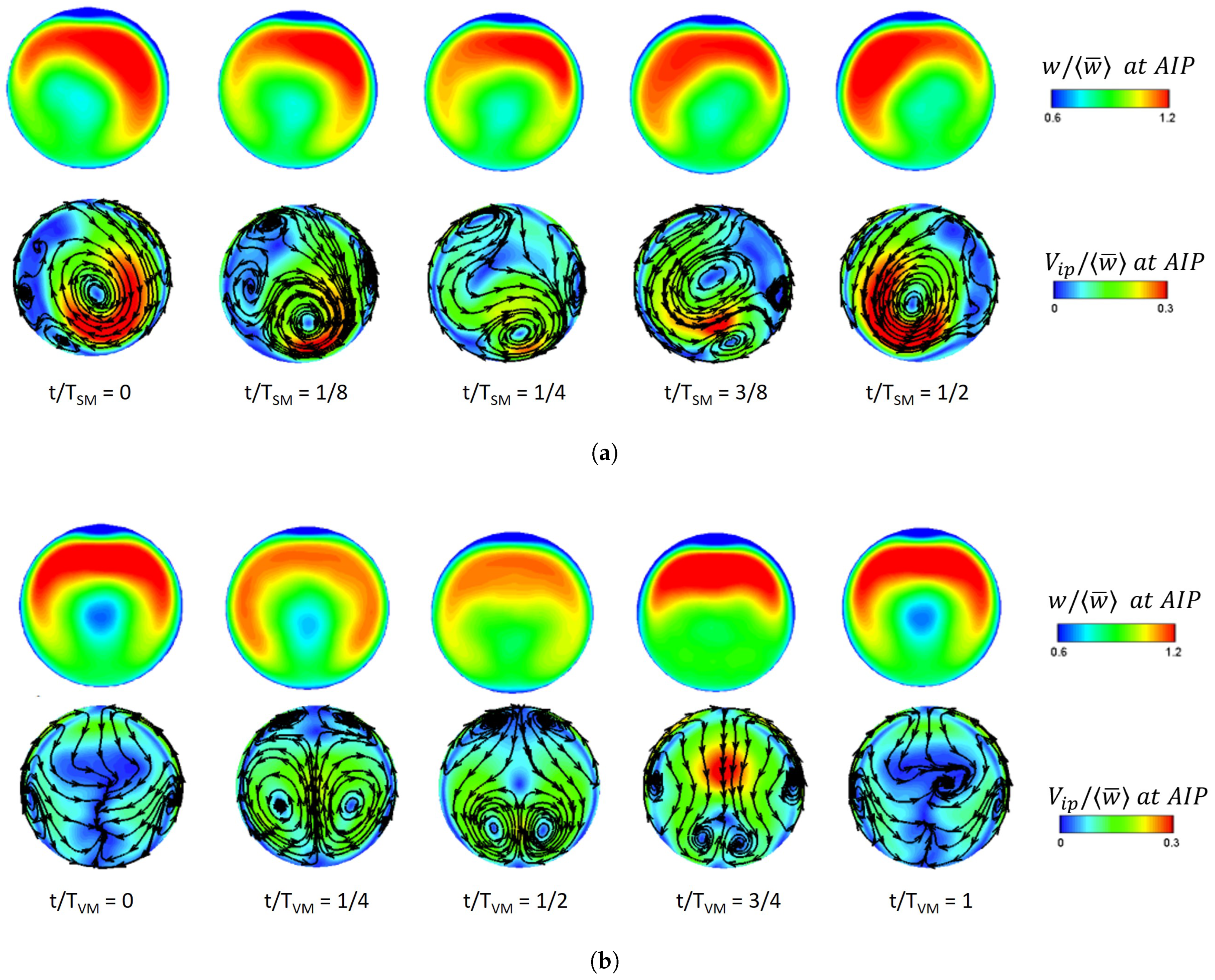
Flow distortions are highly unsteady and complex in space, with the potential to significantly impact the engine’s stability limits [218]. Maintaining stable intake conditions may restrict certain operational ranges, i.e., the rate of engine throttling at high Mach numbers during supersonic descent [219]. An implicit need exists to broaden the operational envelope of an intake system without compromising its overall performance. The disruption in the flow field at the throat is impacting the flow performance at the AIP. With this non-uniformity in the flow field and pressure fluctuating across the entire length of the duct, flow distortion will appear at the AIP. Isolated distortion regions could strongly affect bleed loading, mechanical vibration, and fatigue life [22]; thus, it is of interest to identify how the unsteady intake buzz characteristics would influence the flow distortion. Knowledge in the area of unsteady flow distortion is of vast importance since an early and accurate prediction of such unprecedented events could be crucial in cost savings during the design and testing stages of aircraft development. This would apply in the case of supersonic intake development and integration. Such a body of knowledge could be transferred and further extended to match the requirements of supersonic intakes.
A convoluted intake would ideally deliver a uniform axial flow with evenly distributed pressure fields at the engine face. However, due to the boundary layer development, in the presence of adverse pressure gradients and the duct curvature, separation and secondary flows appear, creating a complex flow field at the AIP, both spatially and temporally. Typically, in a convoluted diffuser, the main loss region appears in the lower sector of the AIP, where the total pressure distortion is heightened due to the growth of the low-momentum boundary layer caused by secondary flows and other losses arising from the flow separation [25]. Swirl distortion may develop when velocity discontinuity exists along the flow. These flow features can appear in a steady-state or time-dependent form, although it is now evident that they are fundamentally unsteady. The magnitude of these flow features depends on the intake/engine mass flow [220].
Several distortion descriptors were previously suggested to characterize patterns of inlet total pressure distortion in industrial intake–engine integration test campaigns. As defined by the S-16 committee in [7], the descriptor formulations were introduced to assess total pressure variations radially and circumferentially across the AIP from pressure data obtained from an intrusive pressure rake positioned at the aerodynamic interface plane (AIP), the interface between the intake and the engine. Additionally, several descriptors for swirl distortion were introduced to depict swirl patterns on the engine face. These formulations encompass expressions to delineate sector swirl (SS), swirl intensity (SI), swirl directivity (SD), and swirl pairs (SP) at the AIP. For more comprehensive illustrations, including example calculations for representative cases, refer to the SAE Aerospace Information Report AIR5686 [8].
It is well understood that steady distortion affects the engine’s stability, as the total pressure loss can have a linear correlation to the reduction in surge margin [221]. More commonly, intake flow distortion has been evaluated through time-averaged flow field statistics at the AIP. While steady flow patterns of distortion can be sufficiently captured using time-averaged properties, this is not the case for flow fields encompassing unsteady distortion, as it is proven that conventional time-averaged measurement methods are unable to accurately reflect the unsteady behavior of the flow [222,223]. The unsteady flow field can substantially differ from the time-averaged flow [165]. It was soon recognized that steady total pressure descriptors were deficient in time-dependent variations, giving rise to dynamic distortion. In an unsteady operation, time-averaged properties can no longer result in an accurate representation of the flow, as this method does not account for the fluctuating property component, leading to different values when compared to instantaneous flow features [216]. Also, the spatially averaged distortion descriptors can obscure major local peak circumferential occurrences that can have a considerable impact on the engine response [22].
Typically, several parameters would influence the intake flow structure and the dynamic distortion. According to Chiereghin et al. [224], intakes with small duct diameters exhibit high swirl angles due to a high adverse pressure gradient, resulting in stronger secondary flows. Additionally, the pressure fluctuation distribution at the AIP does not show remarkable changes with AIP Mach variation. This agrees with work completed by MacManus et al. [164], outlining that Mach and Reynolds number variations have little effect on the unsteady distortion, with the most notable changes arising when the geometry is changed to a higher offset duct. Similarly, the parametric study [224] shows that a higher offset geometric configuration presents a greater low-pressure region at the AIP with the pressure fluctuations concentrating on the central part of the plane. This is also in agreement with unsteady total-pressure characteristics obtained by the experimental S-PIV study by Zachos et al. [27]. In addition, even though low and high offset configurations show common flow characteristics for a M r e f = 0.27, the low-offset configuration at a M r e f = 0.6 represents a change in the flow field topology from a single swirl pair to a set of two contra-rotating swirl pairs. The study further outlines that vortex switching and single-sided swirl patterns are associated with extreme swirl distortion events. MacManus et al. [164] further elaborate that for the S-shaped ducts simulated with different vertical offset configurations (H/L = 50 and H/L = 0.27), the flow field of the main loss region experienced a circumferential variation associated with secondary flows and a vertical perturbation associated with the unsteadiness caused by the centerline separation. Indeed, Gil-Prieto et al. [165] used S-PIV to measure the unsteady three-component velocity field for two S-duct configurations. They found that for both configurations, the most energetic flow mechanisms promote both streamwise and in-plane fluctuations. The study goes on to identify the coherent structures where the vertical mode is associated with the unsteadiness of the centerline shear layer, and the switching mode represents the circumferential velocity variation. In fact, the switching mode is responsible for the Dean vortices becoming dominant, promoting high-intensity bulk swirl events. Figure 12 illustrates the half and full cycles of the lateral and vertical oscillating mechanisms, respectively. The lateral oscillating mechanism is characterized by a dominant swirling vortex that switches direction throughout its cycle, promoting in-plane perturbations. Meanwhile, the vertical oscillating mechanism is characterized by a twin swirl pattern promoting vertical and streamwise fluctuations.
A DDES computational study [225], which is a continuation of the experimental study [165], expands the understanding of the most-energetic coherent structures observed in the S-duct flow field. The study reveals that the swirl-switching mechanism characterized by the alternating clockwise and anticlockwise streamwise vortex is shed from the downstream separation region, at a frequency of St = 0.53, while the vertical perturbation was a result of the spanwise vortex shed along the shear layer originating from the separation region, at a dominant frequency of St = 1.06.
Figure 12. Swirl-switching mechanisms identified in S-shaped ducts [226], (a) Half-cycle of the lateral oscillating mechanism at a dominant frequency of St = 0.54; (b) full cycle of the vertical oscillating mechanism at a dominant frequency of St = 1.11. V i p represents the in-plane velocity modulus, w represents the streamwise velocity component. (Image reproduced with permission by the author).
Aerospace 11 00075 g012
In contrast, experimental methods such as low-bandwidth S-PIV and distortion rakes with low resolution are insufficient in delivering the necessary spatial and temporal resolution for measuring intricate flow fields, as noted in [165,227]. In addressing this limitation, Gil-Prieto et al. [24] employed time-resolved PIV to analyze the spectral characteristics of the velocity flow field in two s-ducts geometric configurations, (H/L = 0.27 and H/L = 0.49) at M r e f = 0.6. The study shows the main frequencies of the flow lie within the estimated critical frequency range and suggest the operability of a typical aero-engine could be affected by the presented unsteadiness. On the one hand, the low offset duct exhibits dominant frequencies in the range of St = 0.26–1.0, whereas the high offset duct is linked to frequencies in the range of St = 0.6–1.0. The first vertical mode is identified as the factor responsible for the out-of-phase streamwise velocity and in-phase velocity fluctuations observed at the top edge of the main loss region. It was postulated that perturbations associated with higher frequencies have a negligible effect on the fan stability [24,220,228]. McLelland et al. [23] demonstrate that the greatest contribution to flow field unsteadiness lies in lower frequencies, in a spectral band range of St = 0.4 to 0.6.
Flow non-uniformity and unsteadiness are further intensified with the growth of the diffusive separation in the duct. Studies revealed that flow distortion is associated with the boundary layer thickness. A thicker incoming boundary layer generates high levels of total pressure distortion [229] and swirl distortion, as it can generate early separation, leading to the growth of the contra-rotating vortices at the AIP [230]. Along with the thickness of the boundary layer, the orientation also plays a role; depending on the boundary layer orientation, compatibility issues may arise between the intake and the compressor [230]. An asymmetric boundary layer can significantly change the spatial distributions of the lateral swirl switching mode and the vertical oscillatory mode of the bulk swirl [23]. With an asymmetric boundary layer profile around the intake centerline, the swirl distortion is reduced, even though the maximum time-averaged swirl angle increased [231]. This section provides a review and summary of recent advancements in the understanding of flow distortion in S-ducts, with an overview presented in Table 5.
It is evident that the frequency of the flow field unsteadiness, the swirl pattern, and orientation presented at the engine face can have a significant effect on the engine performance. Distortion in the intake flow of supersonic intake systems typically exhibits a complex spatial nature, coupled with significant temporal variability. Currently, there is a scarcity of research focused on total pressure distortion within unsteady supersonic intakes [90,108,232], clearly indicating that the AIP experiences a substantial increase in flow distortion when buzz occurs. A more substantial knowledge gap is discerned concerning the dynamic distortion experienced by unsteady supersonic intake systems. To date, there is a limited understanding of the unsteady distortion levels in terms of spatial and temporal distributions resulting from intake buzz. Consequently, significant further work is required, especially considering future aircraft configurations where propulsion integration will be critically important across the operating envelope.
Dynamic distortion can have a critical impact on the operability of gas turbine-based propulsion systems. Future designs may incorporate highly three-dimensional intakes and diffusers, adding complexity to their integration with the propulsion system. Weaknesses in the design process could significantly affect development and certification timelines. This underscores the necessity to establish experimental capabilities dedicated to simulating and assessing unsteady distortions within supersonic intakes, encompassing their interactions with the upstream diffuser flow, leading to the propulsion system. Establishing a model-scale distortion simulation facility is essential to obtain high-fidelity data on how fans respond to distortion under conditions closely resembling those encountered in actual flight. This will bolster confidence in the intake-engine compatibility assessment process used in the early stages of development, as well as serve as a catalyst for comprehending the fundamental flow mechanisms at play.
Several test rigs of this kind have been documented in prior reports, but none of them effectively realized their initial design objectives, mainly due to operational complexities that restricted either the attainable operational range of the test model when installed in the test rig or the faithfulness of the model’s aerodynamics, primarily due to interference from the working section walls [28,29,30]. In detail, Fisher and Ford [28] conducted an experimental study to investigate internal boundary layer separation and viscous losses across various intake configurations. The experimental setup involved integrating the intake model with the wind tunnel diffuser, allowing the use of a significantly larger model than typically feasible in a conventional tunnel of similar dimensions. However, this setup came with some drawbacks, including restricted operational adaptability to nominal conditions and the incapability to simulate the external flow around the model beyond the capture plane. Additionally, access for Schlieren observation was confined to the intake throat and cowl lip regions. Similarly, in the cases of Kimzey and Elis [29] as well as Surber et al. [30], the shock structure around the intake entry was fully or partially generated within a relatively confined onset flow passage. These rigs were designed to represent the aerodynamics of the complete air induction stream tube directly, albeit for a limited range of critical flight conditions, typically between nominal (critical) operation and near-nominal subcritical points, without severe instabilities of the inlet shock train. These test rigs provided a relatively simple way to explore the matching between subsonic diffusers and supersonic entries. However, the results produced were not necessarily representative of the test model’s behavior during larger-scale installed inlet test programs. As a result, the requirement for a bespoke experimental test rig remains necessary to aid the design of future, closely-coupled configurations.
The process of designing this small-scale facility was recently presented by Migliorini et al. [233], with a particular focus on the working test section design to ensure an adequate operational range and representative aerodynamic conditions for the test model. The study provides a detailed account of the ongoing work, encompassing the conceptualization, initial design, and sizing of the working section of the test rig, as well as the design of the exhaust system and the integration of the test model. A key characteristic of this test rig is the ability to integrate advanced instrumentation for both intrusive and, more crucially, non-intrusive distortion measurements at the aerodynamic interface plane (AIP) of the inlet (see Figure 13). Ensuring minimal interference of the test rig’s working section walls with the inlet’s pre-entry flow across a wide range of mass flows is crucial for the rig’s design. Additionally, preventing unstarting, a common issue with high-speed internal flow test rigs, is another key consideration. Subsequent stages of this ongoing effort focus on examining the design parameters that influence the quality of the flow delivered to the working section. This includes assessing the integration of transition ducts and a supersonic nozzle, as well as the design of the radial exhaust system implemented to enable unobstructed optical access to a large part of the subsonic diffuser, enabling the integration of a non-intrusive system for unsteady distortion measurements at the AIP. The objective of this initiative is to establish an experimental framework capable of replicating and thoroughly analyzing unsteady distortions within supersonic intakes. Additionally, it seeks to explore the intricate dynamics of these distortions as they interact with the diffuser flow situated upstream of the propulsion system. Furthermore, this effort aims to address the fundamental gaps identified in this paper, with the ultimate goal of creating methodologies that provide valuable insights for the development of future systems. In essence, this effort aspires not only to simulate and characterize these aerodynamic phenomena but also to contribute to a deeper understanding of their implications and to offer tools for enhancing the design of future propulsion systems.

5. Conclusions

The air induction system remains a major component of the aircraft propulsion system; its sole purpose is to ensure uniform flow delivery to the engine with maximum pressure recovery. However, a significant reduction in the captured air mass flow triggers complex erratic flow features that jeopardize the flow quality in the intake. Flow separation is necessary for the development of intake buzz, but the literature review indicates that the buzz characteristics experienced in an intake can be very case-specific, with each test case exhibiting different oscillation patterns. The diversities of the two trigger mechanisms of the buzz phenomenon and the associated dominant frequencies are noticeably clear in the existing literature. While it is observed that little buzz exhibits smaller or similar oscillation amplitude to big buzz, comparing the frequency of oscillations is more complicated due to its more diverse behavior. This is because the buzz frequency is influenced by several factors, like the intake geometry configuration and the freestream operating conditions. Nevertheless, it is evident that the buzz frequency of a supersonic intake can usually be predicted using analytical solutions from the acoustic theory, in contrast to hypersonic intakes, where this is less likely due to the different flow features existing in the intake throat that blocks the upstream propagation of the acoustic waves. As a result, hypersonic intakes experience different oscillating patterns. However, there are cases in supersonic intake studies where the observed buzz frequency is not the same as the predicted fundamental frequency and the fluctuations experienced in the diffuser are not as would be expected for the fundamental duct acoustic mode. This raises concerns about how uniformly distributed the flow is when delivered to the engine face during a buzz operation and demonstrates the necessity of eliminating this phenomenon for efficient engine operation.
The common thread of flow unsteadiness present in convoluted intakes, high-speed intakes, and isolators, lies in the low-momentum region of the flow. Understanding the risks to engine operability associated with flow unsteadiness, it is important to explore methods that would prevent or suppress such undesirable flow features. Boundary layer bleed, slot, or porous bleed systems have been examined and have shown capabilities in improving the intake operability range, but careful design optimization is required as their geometric parameters and location can significantly impact the flow characteristics. In addition to this, it would be interesting to examine how the boundary layer bleed system behaves in response to different angles of attack. While it is an effective method in delaying instabilities, there is a considerable percentage of lost mass flow, which has a corresponding effect on the intake performance, and a single bleed system is not sufficient to extend the operating range of an intake. Recent emerging technologies have been introduced for actively controlling the flow, consisting of mass injection and energy deposition taking place upstream of the boundary layer, making it less susceptible to adverse pressure gradients. While studies associated with such techniques have demonstrated positive results in successfully suppressing shock oscillation and flow separation, these methods appear to be at the initial stages of development, and the feasibility of practical implementation still remains in question. Also, such methods are expected to be investigated across a range of operating conditions and intake geometries, followed by the optimization of the duration and trigger time of the energy or mass addition.
To gain a better understanding of the flow dynamics and flow topology downstream of the intake buzz oscillations, the study seeks information from the research of unsteady shock trains found in isolators since little relevant work has been conducted in high-speed intakes. It was revealed that the oscillating shock train was not only related to the boundary layer, but also to the interaction of its leading shock and background shock waves. The background shock waves existing in the isolator can significantly influence the shock train shape and positioning and can cause large streamwise and transverse flow non-uniformities in the upstream flow since they are able to propagate upstream through the subsonic portion of the boundary layer. The information becomes more relevant to high-speed intakes when combined with the research outcome by Candon et al. [87], who suggested that it is possible that multiple waves exist in the diffuser, and when they coalesce far upstream, they cause a strong shock oscillation. Limited work has assessed the total pressure distortion in unsteady supersonic intakes and has clearly illustrated the substantial increase in steady-state distortion under such operating conditions. However, the steady-state flow distortion computed in high-speed intakes experiencing shock unsteadiness often neglects the dynamic component of flow distortion. This possibly underestimates the non-uniformity of the flow and potentially creates a lack of understanding of the true impact of these events on engine performance and stability. To date, there is limited understanding of the unsteady distortion levels in terms of spatial and temporal distributions as a result of intake buzz. Additionally, studies assessing the steady-state intake flow distortion in high-speed intakes have mainly focused on total pressure distortion, without giving any attention to swirl distortion. Swirl distortion is a significant component of distortion and a determinant factor for intake-engine compatibility. The examination of total pressure distortion alone is insufficient to determine the engine’s surge margin loss. Therefore, it is encouraged for future work to take into consideration swirl distortion when evaluating the stability of the engine. To capture the essence of dynamic distortion, the study has conducted a literature review on the flow distortion assessed in convoluted intakes. The research illustrates that a major component of flow distortion originates from the separated flow in the lower wall of the S-shaped ducts. The flow field of the main loss region promotes both streamwise and in-plane fluctuations. During extreme swirl distortion events, the flow experiences vortex switching and single-sided vortex patterns. The circumferential variation was associated with secondary flows, while the vertical perturbation was linked to the unsteadiness caused by the centerline separation. The greatest contribution to flow field unsteadiness lies in a spectral band range of St = 0.4 to 0.6, with respect to the average out-of-plane velocity at the AIP. Based on the findings and acknowledging that flow separation plays a significant role in the onset of intake buzz, it is plausible that high-speed intakes, particularly those featuring a circular cross-section at the AIP, might display comparable flow characteristics, such as streamwise and in-plane fluctuations observed in convoluted intakes. However, due to the distinct geometric variations, it is probable that the origin of these fluctuations in high-speed intakes differs from that in convoluted intakes. Consequently, this remains a subject of ongoing research.
Finally, it is recognized that flow instabilities within the air induction system can exert a significant influence on the functionality of gas turbine-based propulsion systems. Looking ahead, the future prospects for evaluating the compatibility between the air induction and the propulsion system highlight the essential need to develop specialized experimental capabilities for simulating and evaluating unsteady distortions within supersonic intakes, encompassing their interactions with the upstream diffuser flow leading to the propulsion system.

Author Contributions

Conceptualization, A.L.P. and P.K.Z.; methodology, A.L.P.; formal analysis, A.L.P.; investigation, A.L.P.; resources, P.K.Z. and D.G.M.; data curation, A.L.P., P.K.Z. and D.G.M.; writing—original draft preparation, A.L.P.; writing—review and editing, A.L.P., P.K.Z. and D.G.M.; visualization, A.L.P. and P.K.Z.; supervision, P.K.Z. All authors have read and agreed to the published version of the manuscript.

Funding

Co-funded by the Erasmus+ Program of the European Union. The European Commission support for the production of this publication does not constitute an endorsement of the contents, which reflects the views only of the authors, and the Commission cannot be held responsible for any use that may be made of the information contained therein.

Data Availability Statement

No new data were created or analyzed in this study. Data sharing is not applicable to this article.

Conflicts of Interest

The authors declare that they have no known competing financial interests or personal relationships that could have appeared to influence the work reported in this paper.

Nomenclature

Abbreviations
AIPaerodynamic interface plane
AOAangle of attack
BSbow shockwave
DBDdielectric barrier discharge
DDESdelayed detached eddy simulations
EBRexit blockage ratio
LAFPAlocalized arc filament plasma actuator
LDVlaser Doppler velocimetry
LESlarge eddy simulations
NSnormal shockwave
OSoblique shockwave
PSJplasma synthetic jet
SSseparation shockwave
SBLIshockwave boundary layer interaction
S-PIVstereo-particle image velocimetry
TPtriple point
operators
. time average
. ¯ area average
Roman symbols
Aarea, m 2
Ddiameter, m
Ffrequency, Hz
Hheight, m
Llength, m
MMach number
StStrouhal number
Uvelocity, m/s
V i p in-plane velocity modulus, m/s
waxial velocity, m/s
sub/super-scripts
quantity at freestream
refreference quantity
maxmaximum quantity

References

  1. Oates, G.C. Aircraft Propulsion Systems Technology and Design; American Institute of Aeronautics and Astronautics: Reston, VA, USA, 1989. [Google Scholar]
  2. Faro, I.D. Supersonic Inlets; North Atlantic Treaty Organization, Advisory Group for Aerospace Research and Development: Brussels, Belgium, 1965. [Google Scholar]
  3. Seddon, J.; Goldsmith, E. Intake Aerodynamics; American Institute of Aeronautics and Astronautics: Reston, VA, USA, 1999. [Google Scholar]
  4. Ebrahimi, A.; Zare Chavoshi, M. Numerical investigation of back pressure and free-stream effects on a mixed compression inlet performance. Sci. Iran. 2017, 25, 751–761. [Google Scholar] [CrossRef]
  5. ARP1420B; Gas Turbine Engine Inlet Flow Distortion Guidelines. SAE International: Warrendale, PA, USA, 2011; p. 24. [CrossRef]
  6. S-16 Turbine Engine Inlet Flow Distortion Committee. Assessment of the Inlet/Engine Total Temperature Distortion Problem; SAE International: Warrendale, PA, USA, 2017; p. 57. [Google Scholar] [CrossRef]
  7. Turbine Engine Inlet Flow Distortion Committee. AIR1419C; Inlet Total-Pressure-Distortion Considerations for Gas-Turbine Engines. Technical Report. SAE International: Warrendale, PA, USA, 2017. [Google Scholar] [CrossRef]
  8. S-16 Turbine Engine Inlet Flow Distortion Committee. A Methodology for Assessing Inlet Swirl Distortion; SAE International: Warrendale, PA, USA, 2017; p. 110. [Google Scholar] [CrossRef]
  9. Das, S.; Prasad, J.K. Starting characteristics of a rectangular supersonic air-intake with Cowl Deflection. Aeronaut. J. 2010, 114, 177–189. [Google Scholar] [CrossRef]
  10. Timofeev, E.; Tahir, R.; Molder, S. On recent developments related to flow starting in Hypersonic Air Intakes. In Proceedings of the 15th AIAA International Space Planes and Hypersonic Systems and Technologies Conference, Dayton, OH, USA, 28 April–1 May 2008. [Google Scholar] [CrossRef]
  11. Wagner, J.L.; Yuceil, K.B.; Valdivia, A.; Clemens, N.T.; Dolling, D.S. Experimental investigation of unstart in an inlet/isolator model in mach 5 flow. AIAA J. 2009, 47, 1528–1542. [Google Scholar] [CrossRef]
  12. Van Wie, D.; Kwok, F.; Walsh, R. Starting characteristics of supersonic inlets. In Proceedings of the 32nd Joint Propulsion Conference and Exhibit, Lake Buena Vista, FL, USA, 1–3 July 1996. [Google Scholar] [CrossRef]
  13. Hawkins, W.; Marquart, E. Two-dimensional generic inlet unstart detection at Mach 2.5-5.0. In Proceedings of the International Aerospace Planes and Hypersonics Technologies, Chattanooga, TN, USA, 3–7 April 1995. [Google Scholar] [CrossRef]
  14. Chang, J.; Fan, Y.; Bao, W.; Yu, D.; Shen, Y. Unstart margin control of hypersonic inlets. Acta Astronaut. 2010, 66, 78–87. [Google Scholar] [CrossRef]
  15. Im, S.; Do, H. Unstart phenomena induced by flow choking in scramjet inlet-isolators. Prog. Aerosp. Sci. 2018, 97, 1–21. [Google Scholar] [CrossRef]
  16. Kantrowitz, A.; Donaldson, C.D. Preliminary Investigation of Supersonic Diffusers; NACA ACR-L5D20; NACA: Boston, MA, USA, 1945. [Google Scholar]
  17. Kantrowitz, A. The Formation and Stability of Normal Shock Waves in Channel Flows; NACA TN 1225; NACA: Boston, MA, USA, 1947. [Google Scholar]
  18. Oswatitsch, K. Pressure Recovery for Missiles with Reaction Propulsion at High Supersonic Speeds (the Efficiency of Shock Diffusers); NACA TM No. 1140; NACA: Boston, MA, USA, 1947. [Google Scholar]
  19. Williams, D.D.; Yost, J.O. Some aspects of inlet/engine flow compatibility. Aeronaut. J. 1973, 77, 483–492. [Google Scholar] [CrossRef]
  20. Wenzel, L.M.; Blaha, R.J. Analysis of Dynamic Inlet Distortion Applied to a Parallel Compressor Model; NASA TM-X-352; NASA: Washington, DC, USA, 1977. [Google Scholar]
  21. Cousins, W.T. History, Philosophy, Physics, and Future Directions of Aircraft Propulsion System/Inlet Integration. In Proceedings of the ASME Turbo Expo 2004 Power for Land, Sea, and Air, Vienna, Austria, 14–17 June 2004. [Google Scholar]
  22. Tanguy, G.; MacManus, D.G.; Garnier, E.; Martin, P.G. Characteristics of unsteady total pressure distortion for a complex aero-engine intake duct. Aerosp. Sci. Technol. 2018, 78, 297–311. [Google Scholar] [CrossRef]
  23. McLelland, G.; MacManus, D.G.; Zachos, P.K.; Gil-Prieto, D.; Migliorini, M. Influence of upstream total pressure profiles on S-duct intake flow distortion. J. Propuls. Power 2020, 36, 346–356. [Google Scholar] [CrossRef]
  24. Gil-Prieto, D.; Zachos, P.K.; MacManus, D.G.; McLelland, G. Unsteady characteristics of S-duct intake flow distortion. Aerosp. Sci. Technol. 2019, 84, 938–952. [Google Scholar] [CrossRef]
  25. Kächele, T.; Rademakers, R.P.; Schneider, T.; Niehuis, R. Numerical simulations of an intake-compressor system. J. Glob. Power Propuls. Soc. 2018, 2, 442–452. [Google Scholar] [CrossRef]
  26. Mehdi, A.; Pachidis, V.; MacManus, D. Effect of Swirl Distortion on Gas Turbine Operability. 2014. Available online: https://dspace.lib.cranfield.ac.uk/handle/1826/12129 (accessed on 1 September 2023).
  27. Zachos, P.K.; MacManus, D.G.; Prieto, D.G.; Chiereghin, N. Flow distortion measurements in convoluted aeroengine intakes. AIAA J. 2016, 54, 2819–2832. [Google Scholar] [CrossRef]
  28. Fisher, S.A.; Ford, D.J. An Investigation of Starting Problems in a Specialised Wind Tunnel for Testing a Rectangular Mixed Compression Intake at Mach 3; Publication 138; Aeronautical Research Laboratories Mechanical Engineering, Department of Supply, Australian Defence Scientific Service: Adelaide, Australia, 1972. [Google Scholar]
  29. Kimzey, W.F.; Ellis, S.H. Supersonic Inlet Simulator—A Tool for Simulation of Realistic Engine Entry Flow Conditions. SAE Int. 1974, 83, 2812–2824. [Google Scholar] [CrossRef]
  30. Syberg, J. Performance of Highly Integrated Inlets for Supersonic Aircraft; AGARD Conference Proceedings No.301; AGARD: Neuilly-sur-Seine, France, 1981. [Google Scholar]
  31. Ferri, A.; Nucci, L.M. The Origin of Aerodynamic Instability of Supersonic Inlets at Subcritical Conditions; NACA RM L50K30; NACA: Boston, MA, USA, 1951. [Google Scholar]
  32. Dailey, C.L. Supersonic diffuser instability. J. Aeronaut. Sci. 1955, 22, 733–749. [Google Scholar] [CrossRef]
  33. Fisher, S.A.; Neale, M.C.; Brooks, A.J. On the Sub-Critical Stability of Variable Ramp Intakes at Mach Numbers Around 2. UK Ministry of Defence Reports and Memoranda R. & M. 1972. Available online: https://reports.aerade.cranfield.ac.uk/handle/1826.2/2987 (accessed on 1 September 2023).
  34. Jungclaus, G. Neue experimentelle Ergebnisse zur Entstehung und Struktur von Ferri- und Dailey-Instabilitäten (“Brummen"). Z. Für Flugwiss. Und Weltraumforsch. (ZFW) 1990, 14, 256–262. [Google Scholar]
  35. Orlin, W.J.; Dunsworth, L.C. A Criterion for Flow Instability in Supersonic Diffuser Inlets; Report No. 5144; Marquardt Aircraft Co.: Los Angeles, CA, USA, 1951. [Google Scholar]
  36. Soltani, M.; Farahani, M.; Asgari Kaji, M. An experimental study of buzz instability in an axisymmetric supersonic inlet. Sci. Iran. 2011, 18, 241–249. [Google Scholar] [CrossRef]
  37. Soltani, M.R.; Sepahi-Younsi, J. Buzz cycle description in an axisymmetric mixed-compression air intake. AIAA J. 2016, 54, 1040–1053. [Google Scholar] [CrossRef]
  38. Abedi, M.; Askari, R.; Soltani, M. Numerical simulation of Inlet Buzz. Aerosp. Sci. Technol. 2020, 97, 105547. [Google Scholar] [CrossRef]
  39. Newsome, R.W. Numerical simulation of near-critical and unsteady, Subcritical Inlet Flow. AIAA J. 1984, 22, 1375–1379. [Google Scholar] [CrossRef]
  40. Lu, P.; Jain, L. Numerical Investigation of Inlet Buzz Flow. J. Propuls. Power 1998, 14, 90–100. [Google Scholar] [CrossRef]
  41. Fujimoto, A.N.N.; Sawada, K. Numerical investigation of Supersonic Inlet with realistic bleed andbypass systems. In Proceedings of the 29th Aerospace Sciences Meeting, Reno, NV, USA, 7–10 January 1991. [Google Scholar] [CrossRef]
  42. Fujiwara, H.M.A.; Murakami, A.; Watanabe, Y. Numerical analysis on shock oscillation of two-dimensional external compression intakes. In Proceedings of the 32nd AIAA Fluid Dynamics Conference and Exhibit, St. Louis, MO, USA, 24–26 June 2002. [Google Scholar] [CrossRef]
  43. Hong, W.; Kim, C. Computational study on Hysteretic Inlet Buzz characteristics under varying mass flow conditions. AIAA J. 2014, 52, 1357–1373. [Google Scholar] [CrossRef]
  44. Trapier, S.; Deck, S.; Duveau, P. Delayed detached-eddy simulation and analysis of Supersonic Inlet Buzz. AIAA J. 2008, 46, 118–131. [Google Scholar] [CrossRef]
  45. Watanabe, Y.; Ueno, A.; Murakami, A. Design Of Top Mounted Supersonic Inlet For Silent Supersonic Technology Demonstrator S3TD. In Proceedings of the 27th Congress of the International Council of the Aeronautical Sciences, Nice, France, 19–24 September 2010. [Google Scholar]
  46. John, B.; Senthilkumar, P. Alterations of cowl lip for the improvement of supersonic-intake performance. J. Appl. Fluid Mech. 2018, 11, 31–41. [Google Scholar] [CrossRef]
  47. Slater, J.W. Design factors for two-dimensional, external-compression supersonic inlets. In Proceedings of the AIAA Scitech 2020 Forum, Orlando, FL, USA, 6–10 January 2020. [Google Scholar] [CrossRef]
  48. Trapier, S.; Duveau, P.; Deck, S. Experimental Study of Supersonic Inlet Buzz. AIAA J. 2006, 44, 2354–2365. [Google Scholar] [CrossRef]
  49. Trapier, S.; Deck, S.; Duveau, P.; Sagaut, P. Time-frequency analysis and detection of Supersonic Inlet Buzz. AIAA J. 2007, 45, 2273–2284. [Google Scholar] [CrossRef]
  50. Nagashima, T.; Obokata, T.; Asanuma, T. Experiment of Supersonic Air Intake Buzz; Institute of Space and Aeronautical Science: Toyko, Japan, 1972; Volume 481, pp. 165–209. [Google Scholar]
  51. Nishizawa, U.; Kameda, M.; Watanabe, Y.; Yamamoto, S. Computational simulation of shock oscillation around a supersonic air-intake. In Proceedings of the 36th AIAA Fluid Dynamics Conference and Exhibit, San Francisco, LA, USA, 5–8 June 2006. [Google Scholar] [CrossRef]
  52. Masuya, G. Aerodynamic performances of a combined Cycle Inlet. J. Propuls. Power 2006, 22, 900–904. [Google Scholar] [CrossRef]
  53. Lu, H.; Yue, L.; Chang, X. Flow characteristics of hypersonic inlets with different cowl-lip blunting methods. Sci. China Phys. Mech. Astron. 2014, 57, 741–752. [Google Scholar] [CrossRef]
  54. Das, S.; Prasad, J.K. Effect of cowl deflection angle in a supersonic air-intake. Def. Sci. J. 2009, 59, 99–105. [Google Scholar] [CrossRef]
  55. Das, S.; Prasad, J.K. Flow field investigation of a rectangular supersonic air-intake with cowl bending. J. Aerosp. Sci. Technol. 2009, 61, 312–324. [Google Scholar] [CrossRef]
  56. Lanson, F.; Stollery, J.L. Some hypersonic intake studies. Aeronaut. J. 2006, 110, 145–156. [Google Scholar] [CrossRef]
  57. Shi, W.; Chang, J.; Wang, Y.; Bao, W.; Liu, X. Buzz Evolution Process Investigation of a two-ramp inlet with translating cowl. Aerosp. Sci. Technol. 2019, 84, 712–723. [Google Scholar] [CrossRef]
  58. Herrmann, D.; Siebe, F.; Gülhan, A. Pressure fluctuations (buzzing) and inlet performance of an airbreathing missile. J. Propuls. Power 2013, 29, 839–848. [Google Scholar] [CrossRef]
  59. Tan, H.; Sun, S.; Yin, Z. Oscillatory flows of rectangular hypersonic inlet unstart caused by downstream mass-flow choking. J. Propuls. Power 2009, 25, 138–147. [Google Scholar] [CrossRef]
  60. Chang, J.; Wang, L.; Bao, W.; Qin, J.; Niu, J.; Xue, W. Novel oscillatory patterns of Hypersonic Inlet Buzz. J. Propuls. Power 2012, 28, 1214–1221. [Google Scholar] [CrossRef]
  61. Soltani, M.; Daliri, A.; Younsi, J.; Farahani, M. Effects of bleed position on the stability of a supersonic inlet. J. Propuls. Power 2016, 32, 1153–1166. [Google Scholar] [CrossRef]
  62. Soltani, M.; Farahani, M. Experimental investigation of effects of Mach number on the flow instability in a supersonic inlet. Exp. Tech. 2011, 37, 46–54. [Google Scholar] [CrossRef]
  63. Chen, H.; Tan, H.J.; Zhang, Q.F.; Zhang, Y. Buzz flows in an external-compression inlet with partially isentropic compression. AIAA J. 2017, 55, 4286–4295. [Google Scholar] [CrossRef]
  64. Chen, H.; Tan, H.; Zhang, Q.; Zhang, Y. Throttling process and buzz mechanism of a supersonic inlet at Overspeed mode. AIAA J. 2018, 56, 1953–1964. [Google Scholar] [CrossRef]
  65. Chen, H.; Tan, H. Buzz flow diversity in a supersonic inlet ingesting strong shear layers. Aerosp. Sci. Technol. 2019, 95, 105471. [Google Scholar] [CrossRef]
  66. Nakayama, T.; Sato, T.; Akatsuka, M.; Hashimoto, A.; Kojima, T.; Taguchi, H. Investigation on shock oscillation phenomenon in a supersonic air inlet. In Proceedings of the 41st AIAA Fluid Dynamics Conference and Exhibit, Honolulu, HI, USA, 27–30 June 2011. [Google Scholar] [CrossRef]
  67. Lee, H.J.; Jeung, I.S. Experimental and numerical investigation on the Supersonic Inlet Buzz with angle of attack. In Proceedings of the 26th International Symposium on Shock Waves, Göttingen, Germany, 15–20 July 2009; Volume 2, pp. 1111–1116. [Google Scholar] [CrossRef]
  68. Chen, H.; Tan, H.; Liu, Y.; Zhang, Q. External-compression supersonic inlet free from violent buzz. AIAA J. 2019, 57, 2513–2523. [Google Scholar] [CrossRef]
  69. Grossman, I.J.; Bruce, P.J. Effect of confinement on shock wave-boundary layer interactions in rectangular intakes. In Proceedings of the 54th AIAA Aerospace Sciences Meeting, San Diego, CA, USA, 4–8 January 2016. [Google Scholar] [CrossRef]
  70. Grossman, I.J.; Bruce, P.J. Confinement effects on regular–irregular transition in shock-wave–boundary-layer interactions. J. Fluid Mech. 2018, 853, 171–204. [Google Scholar] [CrossRef]
  71. Sridhar, T.; Chandrabose, G.; Thanigaiarasu, S. Numerical investigation of geometrical influence on isolator performance. Int. J. Theor. Appl. Mech. 2013, 2, 7–12. [Google Scholar]
  72. Chang, J.; Li, N.; Xu, K.; Bao, W.; Yu, D. Recent research progress on Unstart mechanism, detection and control of Hypersonic Inlet. Prog. Aerosp. Sci. 2017, 89, 1–22. [Google Scholar] [CrossRef]
  73. Tan, H.; Li, L.; Wen, Y.; Zhang, Q. Experimental investigation of the Unstart process of a generic hypersonic inlet. AIAA J. 2011, 49, 279–288. [Google Scholar] [CrossRef]
  74. Tan, H.; Guo, R. Experimental study of the unstable-unstarted condition of a hypersonic inlet at mach 6. J. Propuls. Power 2007, 23, 783–788. [Google Scholar] [CrossRef]
  75. Sekar, K.R.; Karthick, S.K.; Jegadheeswaran, S.; Kannan, R. On the unsteady throttling dynamics and scaling analysis in a typical hypersonic inlet–isolator flow. Phys. Fluids 2020, 32, 126104. [Google Scholar] [CrossRef]
  76. Liu, K.L.; Zhang, K.Y. Numerical investigation of 2-D hypersonic inlet starting characteristic caused by dynamic angle-of-attack. In Proceedings of the 46th AIAA/ASME/SAE/ASEE Joint Propulsion Conference & Exhibit, Nashville, TN, USA, 25–28 July 2010. [Google Scholar] [CrossRef]
  77. Zhang, Q.F.; Tan, H.J.; Sun, S.; Bu, H.X.; Rao, C.Y. Unstart of a hypersonic inlet with side compression caused by downstream choking. AIAA J. 2016, 54, 28–38. [Google Scholar] [CrossRef]
  78. Xu, S.; Wang, Y.; Wang, Z.; Fan, X.; Xiong, B. Experimental investigations of Hypersonic Inlet Unstart/restart process and hysteresis phenomenon caused by angle of attack. Aerosp. Sci. Technol. 2022, 126, 107621. [Google Scholar] [CrossRef]
  79. Chima, R. Analysis of Buzz in a Supersonic Inlet; NASA TM-2012-217612; NASA: Washington, DC, USA, 2012. [Google Scholar]
  80. Grenson, P.; Beneddine, S. Analysis of shock oscillations of an external compression supersonic inlet through unsteady numerical simulations. In Proceedings of the 2018 Applied Aerodynamics Conference, Atlanta, GA, USA, 25–29 June 2018. [Google Scholar] [CrossRef]
  81. Zhu, J.; Luo, W.; Wei, Y.; Yan, C.; You, Y. Acoustic modeling and vibration characteristics of Supersonic Inlet Buzz. Energies 2020, 13, 2048. [Google Scholar] [CrossRef]
  82. Wang, C.; Yang, X.; Xue, L.; Kontis, K.; Jiao, Y. Correlation Analysis of separation shock oscillation and wall pressure fluctuation in unstarted hypersonic inlet flow. Aerospace 2019, 6, 8. [Google Scholar] [CrossRef]
  83. Sterbentz, W.H.; Davids, J. Amplitude of Supersonic Diffuser Flow Pulsations; NACA TN 3572; NACA: Boston, MA, USA, 1955. [Google Scholar]
  84. Yeom, H.; Sung, H.; Yang, V. A numerical analysis of supersonic intake buzz in an axisymmetric ramjet engine. Int. J. Aeronaut. Space Sci. 2015, 16, 165–176. [Google Scholar] [CrossRef]
  85. Kwak, E.; Lee, S. Numerical Study of the effect of exit configurations on Supersonic Inlet Buzz. In Proceedings of the 31st AIAA Applied Aerodynamics Conference, San Diego, CA, USA, 24–27 June 2013. [Google Scholar] [CrossRef]
  86. Grenson, P.; Beneddine, S. Large-Eddy Simulation of a Supersonic Air Inlet in Subcritical Regime; AERO2020+1. 2021. Available online: https://hal.science/hal-03368456/ (accessed on 1 September 2023).
  87. Candon, S.; Loth, E.; Rybalko, M. Near-on-design unsteadiness in a supersonic low-boom inlet. J. Propuls. Power 2016, 32, 360–372. [Google Scholar] [CrossRef]
  88. Kurth, G.; Bauer, C. Air Intake Development for a mach 5+ throttleable ducted rocket propelled lower tier interceptor. In Proceedings of the 51st AIAA/SAE/ASEE Joint Propulsion Conference, Orlando, FL, USA, 27–29 July 2015. [Google Scholar] [CrossRef]
  89. Farahani, M.; Jaberi, A. Study of buzz phenomenon using visualization of external shock structure. Proc. Inst. Mech. Eng. Part G J. Aerosp. Eng. 2018, 233, 2690–2698. [Google Scholar] [CrossRef]
  90. Soltani, M.R.; Sepahi Younsi, J.; Daliri, A. Performance investigation of a supersonic air intake in the presence of the boundary layer suction. Proc. Inst. Mech. Eng. Part G J. Aerosp. Eng. 2015, 229, 1495–1509. [Google Scholar] [CrossRef]
  91. Sepahi-Younsi, J.; Soltani, M.; Abedi, M.; Masdari, M. Experimental investigation into the effects of Mach number and boundary-layer bleed on flow stability of a supersonic air intake. Sci. Iran. 2020, 27, 1197–1205. [Google Scholar] [CrossRef]
  92. K James, J.; Suryan, A.; Kim, H.D. Buzz characteristics and separation bubble dynamics in Supersonic Intake. Aerosp. Sci. Technol. 2021, 115, 106795. [Google Scholar] [CrossRef]
  93. Van, W.; David, M. Scramjet inlets. Scramjet Propuls. 2001, 189, 447–511. [Google Scholar] [CrossRef]
  94. Stephen, E.J.; Hoenisch, S.R.; Riggs, C.J.; Waddel, M.L.; Bolender, M.A.; McLaughlin, T.E. HIFiRE-6 unstart conditions at off-design mach numbers. In Proceedings of the 53rd AIAA Aerospace Sciences Meeting, Kissimmee, FL, USA, 5–9 January 2015. [Google Scholar] [CrossRef]
  95. Yuan, H.C.; Liang, D.W. Analysis of characteristics of restart performance for a hypersonic inlet. J. Propuls. Technol. 2016, 27, 390–398. [Google Scholar]
  96. Jiao, X.; Chang, J.; Wang, Z.; Yu, D. Mechanism study on local unstart of Hypersonic Inlet at high Mach number. AIAA J. 2015, 53, 3102–3112. [Google Scholar] [CrossRef]
  97. Jiao, X.; Chang, J.; Wang, Z.; Yu, D. Investigation of Hypersonic Inlet Pulse-starting characteristics at high Mach number. Aerosp. Sci. Technol. 2016, 58, 427–436. [Google Scholar] [CrossRef]
  98. Jiao, X.; Chang, J.; Wang, Z.; Yu, D. Hysteresis phenomenon of hypersonic inlet at high Mach number. Acta Astronaut. 2016, 128, 657–668. [Google Scholar] [CrossRef]
  99. Soltani, M.R.; Farahani, M. Effects of angle of attack on Inlet Buzz. J. Propuls. Power 2012, 28, 747–757. [Google Scholar] [CrossRef]
  100. NamKoung, H.; Hong, W.; Kim, J.; Yi, J.; Kim, C. Effects of angles of attack and throttling conditions on Supersonic Inlet Buzz. Int. J. Aeronaut. Space Sci. 2012, 13, 296–306. [Google Scholar] [CrossRef]
  101. Boychev, K.; Barakos, G.N.; Steijl, R. Numerical simulations of multiple shock wave boundary layer interactions. In Proceedings of the AIAA Scitech 2021 Forum, Virtual Event, 11–21 January 2021. [Google Scholar] [CrossRef]
  102. Herrmann, D.; Triesch, K. Experimental investigation of isolated inlets for high agile missiles. Aerosp. Sci. Technol. 2006, 10, 659–667. [Google Scholar] [CrossRef]
  103. Herrmann, D.; Triesch, K.; Gülhan, A. Experimental study of chin intakes for airbreathing missiles with high agility. J. Propuls. Power 2008, 24, 236–244. [Google Scholar] [CrossRef]
  104. Guo, S.; Gao, W.; Zhang, E.; Li, Z.; Yang, J. Effects of attack angle on starting performance of a hypersonic inlet. In Proceedings of the 30th International Symposium on Shock Waves 1, Nagoya, Japan, 9–14 July 2017; pp. 155–160. [Google Scholar] [CrossRef]
  105. Liu, K.; Zhang, K. Experiment of dynamic angle-of-attack on a side wall compression scramjet inlet at mach 3.85. In Proceedings of the 17th AIAA International Space Planes and Hypersonic Systems and Technologies Conference, San Francisco, CA, USA, 11–14 April 2011. [Google Scholar] [CrossRef]
  106. Zuo, F.; Molder, S.; Chen, G. Performance of wavecatcher intakes at angles of attack and sideslip. Chin. J. Aeronaut. 2021, 34, 244–256. [Google Scholar] [CrossRef]
  107. Sepahi-Younsi, J. Effects of boundary-layer bleed parameters on supersonic intake buzz. Aerosp. Sci. Technol. 2022, 120, 107246. [Google Scholar] [CrossRef]
  108. Sepahi-Younsi, J.; Esmaeili, S.; Forouzi Feshalami, B.; Pellerito, V.; Hassanalian, M. Performance enhancement of an external compression intake by the boundary layer suction. In Proceedings of the AIAA Propulsion and Energy 2019 Forum, Indianapolis, IN, USA, 19–22 August 2019. [Google Scholar] [CrossRef]
  109. Petha Sethuraman, V.R.; Kim, T.H.; Kim, H.D. Effects of back pressure perturbation on shock train oscillations in a rectangular duct. Acta Astronaut. 2021, 179, 525–535. [Google Scholar] [CrossRef]
  110. Sethuraman, V.R.P.; Kim, T.H.; Kim, H.D. Control of the oscillations of shock train using boundary layer suction. Aerosp. Sci. Technol. 2021, 118, 107012. [Google Scholar] [CrossRef]
  111. Reza Maadi, S.; Sepahi-Younsi, J. Effects of bleed type on the performance of a supersonic intake. Exp. Therm. Fluid Sci. 2022, 132, 110568. [Google Scholar] [CrossRef]
  112. Slater, J.W.; Saunders, J.D. Modeling of fixed-exit porous bleed systems for supersonic inlets. J. Propuls. Power 2010, 26, 193–202. [Google Scholar] [CrossRef]
  113. Slater, J.W. Improvements in modeling 90-degree bleed holes for supersonic inlets. J. Propuls. Power 2012, 28, 773–781. [Google Scholar] [CrossRef]
  114. Choe, Y.; Kim, C.; Kim, K. Effects of optimized bleed system on Supersonic Inlet Performance and buzz. J. Propuls. Power 2020, 36, 211–222. [Google Scholar] [CrossRef]
  115. Giehler, J.; Grenson, P.; Bur, R. Porous Bleed Boundary Conditions for Shock-Induced Boundary Layer Separation Control. In Proceedings of the 56th 3AF International Conference AERO2022, Toulose, France, 28–30 March 2022. [Google Scholar]
  116. Wang, C.; Eri, Q.; Kong, B.; Wang, Y.; Ding, W. Novel simplified numerical simulation method for modeling bleed holes in supersonic inlets. AIAA J. 2022, 60, 6926–6939. [Google Scholar] [CrossRef]
  117. Soltani, M.R.; Sepahi-Younsi, J.; Farahani, M. Effects of boundary-layer bleed parameters on supersonic intake performance. J. Propuls. Power 2015, 31, 826–836. [Google Scholar] [CrossRef]
  118. Kang, K.; Kato, N.; Im, S.; Do, H. Fast-acting boundary-layer suction control of unstarting flows in an ethylene-fueled dual-mode scramjet. AIAA J. 2021, 59, 3106–3117. [Google Scholar] [CrossRef]
  119. Suryanarayana, G.K.; Dubey, R. Image analyses of supersonic air-intake buzz and control by natural ventilation. J. Vis. 2017, 20, 711–727. [Google Scholar] [CrossRef]
  120. Suryanarayana, G.K.; Dubey, R. Performance enhancement of a ramjet air intake by passive bleed of Boundary Layer. J. Spacecr. Rocket. 2019, 56, 875–886. [Google Scholar] [CrossRef]
  121. Ogura, S.; Fujii, M.; Hoshiya, Y.; Fujimori, Y.; Sato, T.; Taguchi, H.; Kojima, T.; Oki, J. Experimental study of high-speed air intake performance by side clearance. Aerosp. Sci. Technol. 2022, 123, 107439. [Google Scholar] [CrossRef]
  122. Griggs, C.F. An Investigation of Two Methods of Suppressing Shock Oscillation Ahead of Conical Centre-body Intakes; HER MAJESTY’S STATION OFFICE. 1962; C.P. No. 605. Available online: https://reports.aerade.cranfield.ac.uk/bitstream/handle/1826.2/618/arc-cp-0605.pdf?sequence=1 (accessed on 1 September 2023).
  123. Ferrero, A. Control of a supersonic inlet in off-design conditions with plasma actuators and bleed. Aerospace 2020, 7, 32. [Google Scholar] [CrossRef]
  124. Loth, E.; Roos, F.; Davis, D.; Mace, J.; Jaiman, R.; White, S.; Dutton, C.; Dutton, C. Mesoflap and Bleed Flow Control for a mach 2 inlet. In Proceedings of the 42nd AIAA Aerospace Sciences Meeting and Exhibit, Reno, NV, USA, 5–8 January 2004. [Google Scholar] [CrossRef]
  125. Karbasizadeh, M.; Babaei, A.; Bazazzadeh, M.; Menshadi, M. Optimization of slot geometry in shock wave boundary layer interaction phenomenon by using CFD–ann–ga cycle. Aerosp. Sci. Technol. 2017, 71, 163–171. [Google Scholar] [CrossRef]
  126. Zhang, J.; Yuan, H.; Wang, Y.; Huang, G. Experiment and numerical investigation of flow control on a Supersonic Inlet Diffuser. Aerosp. Sci. Technol. 2020, 106, 106182. [Google Scholar] [CrossRef]
  127. Yuan, H.; Liu, F.; Wang, X.; Zhou, Z. Design and analysis of a supersonic axisymmetric inlet based on controllable bleed slots. Aerosp. Sci. Technol. 2021, 118, 107008. [Google Scholar] [CrossRef]
  128. Yuan, H.; Zhang, J.; Wang, Y.; Huang, G. Experimental and numerical investigation on a supersonic inlet with large bleed window. Aeronaut. J. 2021, 126, 425–449. [Google Scholar] [CrossRef]
  129. Cai, F.; Huang, X. Study on self-excited oscillation suppression of supersonic inlet based on parallel cavity. Front. Energy Res. 2022, 10, 884540. [Google Scholar] [CrossRef]
  130. Babinsky, H.; Ogawa, H. SBLI control for wings and inlets. Shock Waves 2008, 18, 89–96. [Google Scholar] [CrossRef]
  131. Babinsky, H. Understanding Micro-Ramp Control of Supersonic Shock Wave Boundary Layer Interactions; Technical Report 0074; Air Force Research Laboratory, United States Air Force: Wright-Patterson Air Force Base, OH, USA, 2007. [Google Scholar] [CrossRef]
  132. Titchener, N.; Babinsky, H. A review of the use of vortex generators for mitigating shock-induced separation. Shock Waves 2015, 25, 473–494. [Google Scholar] [CrossRef]
  133. Vyas, M.; Hirt, S.; Chima, R.; Davis, D.; Wayman, T. Experimental investigation of micro vortex generators on a low boom supersonic inlet (invited). In Proceedings of the 29th AIAA Applied Aerodynamics Conference, Honolulu, HI, USA, 27–30 June 2011. [Google Scholar] [CrossRef]
  134. Herges, T.; Dutton, J.; Elliott, G. High-speed schlieren analysis of Buzz in a relaxed-compression supersonic inlet. In Proceedings of the 48th AIAA/ASME/SAE/ASEE Joint Propulsion Conference & Exhibit, Atlanta, GA, USA, 30 July–1 September 2012. [Google Scholar] [CrossRef]
  135. Baydar, E.; Lu, F.K.; Slater, J.W. Vortex Generators in a Two-Dimensional External-Compression Supersonic Inlet. J. Propuls. Power 2018, 34. [Google Scholar] [CrossRef]
  136. Castner, R.S.; Simerly, S.; Rankin, M. Supersonic Inlet test for a Quiet Supersonic Transport Technology Demonstrator in the NASA Glenn 8-foot by 6-foot supersonic wind tunnel. In Proceedings of the 2018 Applied Aerodynamics Conference, Atlanta, GA, USA, 25–29 June 2018. [Google Scholar] [CrossRef]
  137. Gao, W.; Li, Z.; Yang, J.; Zeng, Y. Effects of trips on the oscillatory flow of an axisymmetric hypersonic inlet with downstream throttle. Chin. J. Aeronaut. 2018, 31, 225–236. [Google Scholar] [CrossRef]
  138. Gao, W.; Chen, J.; Liu, C.; Li, Z.; Yang, J.; Zeng, Y. Effects of vortex generators on unsteady unstarted flows of an axisymmetric inlet with nose bluntness. Aerosp. Sci. Technol. 2020, 104, 106021. [Google Scholar] [CrossRef]
  139. Gahlot, N.K.; Singh, N.K. Control of shock-induced separation inside air intake by vortex generators. Heat Transf. 2021, 51, 766–788. [Google Scholar] [CrossRef]
  140. Valdivia, A.; Yuceil, K.B.; Wagner, J.L.; Clemens, N.T.; Dolling, D.S. Control of Supersonic Inlet-isolator unstart using active and passive vortex generators. AIAA J. 2014, 52, 1207–1218. [Google Scholar] [CrossRef]
  141. Teh, E.J.; Johansen, C. Effect of particle momentum transfer on an oblique-shock-wave/laminar-boundary-layer interaction. Acta Astronaut. 2016, 128, 431–439. [Google Scholar] [CrossRef]
  142. Jagannathan, R.; Hinman, W.S.; Johansen, C. Performance assessment of supersonic and hypersonic intake systems with nano-particle injection. Acta Astronaut. 2019, 159, 609–621. [Google Scholar] [CrossRef]
  143. Titchener, N. An Experimental Investigation of Flow Control for Supersonic Inlets. Ph.D. Thesis, University of Cambridge, Cambridge, UK, 2013. [Google Scholar]
  144. Narayanaswamy, V.; Raja, L.L.; Clemens, N.T. Control of unsteadiness of a shock wave/turbulent boundary layer interaction by using a pulsed-plasma-jet actuator. Phys. Fluids 2012, 24, 076101. [Google Scholar] [CrossRef]
  145. Jagannathan, R.; Johansen, C. Stability Analysis of high-speed intakes with nanoparticle injection. AIAA J. 2021, 59, 1786–1797. [Google Scholar] [CrossRef]
  146. Wang, J.; Feng, L. Plasma actuator. In Flow Control Techniques and Applications; Cambridge Aerospace Series; Cambridge University Press: Cambridge, UK, 2018; pp. 206–245. [Google Scholar] [CrossRef]
  147. Grossman, K.; Bohdan, C.; VanWie, D. Sparkjet actuators for Flow Control. In Proceedings of the 41st Aerospace Sciences Meeting and Exhibit, Reno, NV, USA, 6–9 January 2003. [Google Scholar] [CrossRef]
  148. Grossman, K.; Cybyk, B.; VanWie, D.; Rigling, M. Characterization of SparkJet actuators for Flow Control. In Proceedings of the 42nd AIAA Aerospace Sciences Meeting and Exhibit, Reno, NV, USA, 5–8 January 2004. [Google Scholar] [CrossRef]
  149. Narayanaswamy, V.; Shin, J.; Clemens, N.; Raja, L. Investigation of plasma-generated jets for supersonic flow control. In Proceedings of the 46th AIAA Aerospace Sciences Meeting and Exhibit, Reno, NV, USA, 7–10 January 2008. [Google Scholar] [CrossRef]
  150. Greene, B.R.; Clemens, N.T.; Magari, P.; Micka, D. Control of mean separation in shock boundary layer interaction using pulsed plasma jets. Shock Waves 2014, 25, 495–505. [Google Scholar] [CrossRef]
  151. Webb, N.; Clifford, C.; Samimy, M. Control of oblique shock wave/boundary layer interactions using plasma actuators. Exp. Fluids 2013, 54, 1545. [Google Scholar] [CrossRef]
  152. Leonov, S.B.; Yarantsev, D.A. Near-surface electrical discharge in supersonic airflow: Properties and flow control. J. Propuls. Power 2008, 24, 1168–1181. [Google Scholar] [CrossRef]
  153. Leonov, S.; Falempin, F.; Yarantsev, D.; Firsov, A.; Miller, A. Active steering of shock waves in compression ramp by nonuniform plasma. In Proceedings of the 48th AIAA Aerospace Sciences Meeting Including the New Horizons Forum and Aerospace Exposition, Orlando, FL, USA, 4–7 January 2010. [Google Scholar] [CrossRef]
  154. Yan, H.; Liu, F.; Xu, J.; Xue, Y. Study of oblique shock wave control by surface arc discharge plasma. AIAA J. 2017, 56, 532–541. [Google Scholar] [CrossRef]
  155. Falempin, F.; Firsov, A.A.; Yarantsev, D.A.; Goldfeld, M.A.; Timofeev, K.; Leonov, S.B. Plasma control of shock wave configuration in off-design mode of M = 2 Inlet. Exp. Fluids 2015, 56, 54. [Google Scholar] [CrossRef]
  156. Liu, F.; Yan, H.; Zhan, W.; Xue, Y. Effects of steady and pulsed discharge arcs on shock wave control in mach 2.5 flow. Aerosp. Sci. Technol. 2019, 93, 105330. [Google Scholar] [CrossRef]
  157. Zhang, C.; Yang, H.; Liang, H.; Guo, S. Plasma-based experimental investigation of double compression ramp shock wave/boundary layer interaction control. J. Phys. D Appl. Phys. 2022, 55, 325202. [Google Scholar] [CrossRef]
  158. Pham, H.S.; Shoda, T.; Tamba, T.; Iwakawa, A.; Sasoh, A. Impacts of laser energy deposition on flow instability over double-cone model. AIAA J. 2017, 55, 2992–3000. [Google Scholar] [CrossRef]
  159. Pham, H.S.; Myokan, M.; Tamba, T.; Iwakawa, A.; Sasoh, A. Effects of repetitive laser energy deposition on supersonic duct flows. AIAA J. 2018, 56, 542–553. [Google Scholar] [CrossRef]
  160. Russell, A.; Myokan, M.; Bottini, H.; Sasoh, A.; Zare-Behtash, H.; Kontis, K. Application of laser energy deposition to improve performance for high speed intakes. Propuls. Power Res. 2020, 9, 15–25. [Google Scholar] [CrossRef]
  161. Wang, H.; Hu, W.; Xie, F.; Li, J.; Jia, Y.; Yang, Y. Control effects of a high-frequency pulsed discharge on a hypersonic separated flow. Phys. Fluids 2022, 34, 066102. [Google Scholar] [CrossRef]
  162. Sasoh, A.; Myokan, M.; Kubota, A.; Maeda, K.; Wu, Y.L. Impacts of repetitive laser pulse energy deposition on supersonic intakes. In Proceedings of the AIAA Aviation 2019 Forum, Dallas, TX, USA, 17–21 June 2019. [Google Scholar] [CrossRef]
  163. Myokan, M.; Kubota, A.; Iwakawa, A.; Sasoh, A. Repetitive energy deposition at a supersonic intake in subcritical and Buzz Modes. AIAA J. 2020, 58, 107–117. [Google Scholar] [CrossRef]
  164. MacManus, D.G.; Chiereghin, N.; Prieto, D.G.; Zachos, P. Complex aeroengine intake ducts and dynamic distortion. AIAA J. 2017, 55, 2395–2409. [Google Scholar] [CrossRef]
  165. Gil-Prieto, D.; MacManus, D.G.; Zachos, P.K.; Tanguy, G.; Menzies, K.R. Convoluted intake distortion measurements using stereo particle image velocimetry. AIAA J. 2017, 55, 1878–1892. [Google Scholar] [CrossRef]
  166. Migliorini, M.; Zachos, P.K.; MacManus, D.G.; Haladuda, P. S-duct flow distortion with non-uniform inlet conditions. Proc. Inst. Mech. Eng. Part G J. Aerosp. Eng. 2023, 237, 357–373. [Google Scholar] [CrossRef]
  167. Sullins, G.; McLafferty, G. Experimental results of shock trains in rectangular ducts. In Proceedings of the AlAA 4th International Aerospace Planes Conference, Orlando, FL, USA, 1–4 December 1992. [Google Scholar] [CrossRef]
  168. Billig, F.S.; Pandolfini, P.P.; Corda, S. Design Techniques for Dual Mode Ram Scramjet Combustors. In Proceedings of the AGARD 75th Symposium of Hypersonic Combined Cycle Propulsion, Madrid, Spain, 28 May–1 June 1990; pp. 1–20. [Google Scholar]
  169. Matsuo, K.; Miyazato, Y.; Kim, H. Shock train and pseudo-shock phenomena in internal gas flows. Prog. Aerosp. Sci. 1999, 35, 33–100. [Google Scholar] [CrossRef]
  170. Sullins, G.A. Demonstration of mode transition in a scramjet combustor. J. Propuls. Power 1993, 9, 515–520. [Google Scholar] [CrossRef]
  171. Hunt, R.L.; Gamba, M. On the origin and propagation of perturbations that cause shock train inherent unsteadiness. J. Fluid Mech. 2018, 861, 815–859. [Google Scholar] [CrossRef]
  172. Gaitonde, D.V. Progress in shock wave/boundary layer interactions. Prog. Aerosp. Sci. 2015, 72, 80–99. [Google Scholar] [CrossRef]
  173. Gnani, F.; Zare-Behtash, H.; Kontis, K. Pseudo-shock waves and their interactions in high-speed intakes. Prog. Aerosp. Sci. 2016, 82, 36–56. [Google Scholar] [CrossRef]
  174. Huang, H.; Tan, H.; Li, F.; Tang, X.; Qin, Y.; Xie, L.; Xu, Y.; Li, C.; Gao, S.; Zhang, Y.; et al. A review of the shock-dominated flow in a hypersonic inlet/isolator. Prog. Aerosp. Sci. 2023, 143, 100952. [Google Scholar] [CrossRef]
  175. Gnani, F. Investigation on Supersonic High-Speed Internal Flows and the Tools to Study Their Interactions. Ph.D. Thesis, University of Glasgow, Glasgow, UK, 2018. [Google Scholar]
  176. Sajben, M.; Kroutil, J.C. Effects of initial boundary-layer thickness on transonic diffuser flows. AIAA J. 1981, 19, 1386–1393. [Google Scholar] [CrossRef]
  177. Su, W.; Zhang, K. Back-pressure effects on the hypersonic inlet-isolator Pseudoshock motions. J. Propuls. Power 2013, 29, 1391–1399. [Google Scholar] [CrossRef]
  178. Hsieh, T.; Coakley, T. Downstream boundary effects on the frequency of self-excited oscillations in Transonic Diffuser flows. In Proceedings of the 25th AIAA Aerospace Sciences Meeting, Reno, NV, USA, 24–26 March 1987. [Google Scholar] [CrossRef]
  179. Gawehn, T.; Gülhan, A.; Al-Hasan, N.S.; Schnerr, G.H. Experimental and numerical analysis of the structure of pseudo-shock systems in Laval nozzles with parallel side walls. Shock Waves 2010, 20, 297–306. [Google Scholar] [CrossRef]
  180. Ligrani, P.; Cox, M.; Goethals, K. Spatial coherence of low-frequency unsteadiness associated with a normal shock wave. Aerosp. Sci. Technol. 2021, 112, 106637. [Google Scholar] [CrossRef]
  181. Pirozzoli, S.; Larsson, J.; Nichols, J.; Bernardini, M.; Morgan, B.; Lele, S. Analysis of unsteady effects in shock/boundary layer interactions. In Proceedings of the Summer Program, Stanford, CA, USA, 23–26 July 2010; pp. 153–164. [Google Scholar]
  182. Hou, W.; Chang, J.; Xie, Z.; Wang, Y.; Wu, L.; Bao, W. Behavior and flow mechanism of shock train self-excited oscillation influenced by background waves. Acta Astronaut. 2020, 166, 29–40. [Google Scholar] [CrossRef]
  183. Ikui, T.; Matsuo, K.; Nagai, M.; Honjo, M. Oscillation phenomena of pseudo-shock waves. Bull. JSME 1974, 17, 1278–1285. [Google Scholar] [CrossRef]
  184. Yamane, R.; Kondo, E.; Tomita, Y.; Sakae, N. Vibration of pseudo-shock in straight duct: 1st report, fluctuation of Static Pressure. Trans. Jpn. Soc. Mech. Eng. Ser. B 1983, 49, 2326–2335. [Google Scholar] [CrossRef]
  185. Sugiyama, H.; Takeda, H.; Zhang, J.; Okuda, K.; Yamagishi, H. Locations and oscillation phenomena of pseudo-shock waves in a straight rectangular duct. JSME Int. J. Ser. 2 Fluids Eng. Heat Transf. Power Combust. Thermophys. Prop. 1988, 31, 9–15. [Google Scholar] [CrossRef]
  186. Lustwerk, F. The Influence of Boundary Layer on the “Normal” Shock Configuration; Massachusetts Institute of Technology, Guided Missiles Program: Cambridge, MA, USA, 1950. [Google Scholar]
  187. Fiévet, R.; Koo, H.; Raman, V.; Auslender, A.H. Numerical investigation of shock-train response to inflow boundary-layer variations. AIAA J. 2017, 55, 2888–2901. [Google Scholar] [CrossRef]
  188. Bruce, P.J.; Babinsky, H. Unsteady Shock Wave Dynamics. J. Fluid Mech. 2008, 603, 463–473. [Google Scholar] [CrossRef]
  189. Wang, C.; Cheng, C.; Cheng, K.; Xue, L. Unsteady behavior of oblique shock train and boundary layer interactions. Aerosp. Sci. Technol. 2018, 79, 212–222. [Google Scholar] [CrossRef]
  190. Klomparens, R.; Driscoll, J.F.; Gamba, M. Response of a shock train to downstream back pressure forcing. In Proceedings of the 54th AIAA Aerospace Sciences Meeting, San Diego, CA, USA, 4–8 January 2016. [Google Scholar] [CrossRef]
  191. Tan, H.J.; Sun, S.; Huang, H.X. Behavior of shock trains in a hypersonic inlet/isolator model with complex background waves. Exp. Fluids 2012, 53, 1647–1661. [Google Scholar] [CrossRef]
  192. Waltrup, P.J.; Billig, F.S. Prediction of precombustion wall pressure distributions in scramjet engines. J. Spacecr. Rocket. 1973, 10, 620–622. [Google Scholar] [CrossRef]
  193. Deng, R.; Kim, H.D.; Chen, Q. Effects of back pressure fluctuation on pseudo-shock waves in a rectangular duct. J. Mech. Sci. Technol. 2020, 34, 4649–4655. [Google Scholar] [CrossRef]
  194. Cheng, C.; Wang, C.; Cheng, K. Response of an oblique shock train to downstream periodic pressure perturbations. Proc. Inst. Mech. Eng. Part G J. Aerosp. Eng. 2017, 233, 57–70. [Google Scholar] [CrossRef]
  195. Wang, Z.; Chang, J.; Wu, G.; Yu, D. Experimental investigation of shock train behavior in a supersonic isolator. Phys. Fluids 2021, 33, 046103. [Google Scholar] [CrossRef]
  196. Leonard, M.D.; Narayanaswamy, V. Investigation of shock dynamics in an Axisymmetric Inlet/isolator with attached boundary layers. J. Fluid Mech. 2020, 908, A42. [Google Scholar] [CrossRef]
  197. Bur, R.; Benay, R.; Galli, A.; Berthouze, P. Experimental and numerical study of forced shock-wave oscillations in a transonic channel. Aerosp. Sci. Technol. 2006, 10, 265–278. [Google Scholar] [CrossRef]
  198. Xiong, B.; Wang, Z.; Fan, X.; Wang, Y. Experimental study on the flow separation and self-excited oscillation phenomenon in a rectangular duct. Acta Astronaut. 2017, 133, 158–165. [Google Scholar] [CrossRef]
  199. Xiong, B.; Fan, X.; Wang, Z.; Tao, Y. Analysis and modelling of Unsteady Shock Train motions. J. Fluid Mech. 2018, 846, 240–262. [Google Scholar] [CrossRef]
  200. Koo, H.; Raman, V. Large-eddy simulation of a Supersonic Inlet-Isolator. AIAA J. 2012, 50, 1596–1613. [Google Scholar] [CrossRef]
  201. Jiao, X.; Chang, J.; Wang, Z.; Yu, D. Periodic forcing of a shock train in a scramjet inlet-isolator at Overspeed Condition. Acta Astronaut. 2018, 143, 244–254. [Google Scholar] [CrossRef]
  202. Fan, X.; Bing, X.; Wang, Y.; Yuan, T. Experimental study on the self-excited oscillation and the forced oscillation of shock train in a rectangular isolator. In Proceedings of the 21st AIAA International Space Planes and Hypersonics Technologies Conference, Xiamen, China, 6–9 March 2017. [Google Scholar] [CrossRef]
  203. Hou, W.; Chang, J.; Wang, Y.; Kong, C.; Bao, W. Experimental study on the forced oscillation of shock train in an isolator with background waves. Aerosp. Sci. Technol. 2020, 106, 106129. [Google Scholar] [CrossRef]
  204. Wang, Z.; Chang, J.; Hou, W.; Yu, D. Propagation of shock-wave/boundary-layer interaction unsteadiness in attached and separated flows. AIP Adv. 2020, 10, 105011. [Google Scholar] [CrossRef]
  205. Wang, Z.; Chang, J.T.; Hou, W.X.; Yu, D.R. Low-frequency unsteadiness of shock-wave/boundary-layer interaction in an isolator with background waves. Phys. Fluids 2020, 32, 056105. [Google Scholar] [CrossRef]
  206. Babinsky, H.; Oorebeek, J.; Cottingham, T. Corner effects in reflecting oblique shock-wave/boundary-layer interactions. In Proceedings of the 51st AIAA Aerospace Sciences Meeting including the New Horizons Forum and Aerospace Exposition, Grapevine, TX, USA, 7–10 January 2013. [Google Scholar] [CrossRef]
  207. Wang, B.; Sandham, N.D.; Hu, Z.; Liu, W. Numerical study of oblique shock-wave/boundary-layer interaction considering sidewall effects. J. Fluid Mech. 2015, 767, 526–561. [Google Scholar] [CrossRef]
  208. Geerts, J.S.; Yu, K.H. Shock train/boundary-layer interaction in rectangular isolators. AIAA J. 2016, 54, 3450–3464. [Google Scholar] [CrossRef]
  209. Huang, H.; Tan, H.; Sun, S.; Ling, Y. Evolution of supersonic corner vortex in a hypersonic inlet/isolator model. Phys. Fluids 2016, 28, 126101. [Google Scholar] [CrossRef]
  210. Huang, H.; Sun, S.; Tan, H.; Ning, L.; Wang, J. Characterization of two typical unthrottled flows in hypersonic inlet/Isolator Models. J. Aircr. 2015, 52, 1715–1721. [Google Scholar] [CrossRef]
  211. Morajkar, R.R.; Klomparens, R.L.; Eagle, W.E.; Driscoll, J.F.; Gamba, M.; Benek, J.A. Relationship between intermittent separation and vortex structure in a three-dimensional shock/boundary-layer interaction. AIAA J. 2016, 54, 1862–1880. [Google Scholar] [CrossRef]
  212. Liu, X.; Liang, J.; Wang, Y. Flow mechanism in a hypersonic sidewall compression inlet with a rectangular-to-circular isolator. J. Spacecr. Rocket. 2016, 53, 549–557. [Google Scholar] [CrossRef]
  213. Huang, H.x.; Tan, H.j.; Sun, S.; Sheng, F.j. Unthrottled flows with complex background waves in curved isolators. AIAA J. 2017, 55, 2942–2955. [Google Scholar] [CrossRef]
  214. Huang, H.; Tan, H.; Sun, S.; Wang, Z. Behavior of Shock Train in Curved Isolators with Complex Background Waves. AIAA J. 2018, 56, 329–341. [Google Scholar] [CrossRef]
  215. Liang, G.; Huang, H.; Tan, H.; Luo, Z.; Tang, X.; Li, C.; Cai, J. Shock train/glancing shock/boundary layer interaction in a curved isolator with sidewall contraction. Phys. Fluids 2022, 34, 116106. [Google Scholar] [CrossRef]
  216. Bowditch, D.; Coltrin, R. A survey of Inlet/engine distortion compatibility. In Proceedings of the 19th Joint Propulsion Conference, Seattle, WA, USA, 27–29 June 1983. [Google Scholar] [CrossRef]
  217. Doll, U.; Migliorini, M.; Baikie, J.; Zachos, P.K.; Röhle, I.; Melnikov, S.; Steinbock, J.; Dues, M.; Kapulla, R.; MacManus, D.G.; et al. Non-intrusive flow diagnostics for Unsteady Inlet Flow Distortion Measurements in novel aircraft architectures. Prog. Aerosp. Sci. 2022, 130, 100810. [Google Scholar] [CrossRef]
  218. Davis, M.; Hale, A.; Beale, D. An argument for enhancement of the current inlet distortion ground test practice for aircraft gas turbine engines. J. Turbomach. 2002, 124, 235–241. [Google Scholar] [CrossRef]
  219. Young, P. Propulsion controls on the Concorde. J. R. Aeronaut. Soc. 1966, 70, 863–881. [Google Scholar] [CrossRef]
  220. Bissinger, N.C.; Breuer, T. Basic principles—Gas turbine compatibility—Intake aerodynamic aspects. In Encyclopedia of Aerospace Engineering; John Wiley & Sons, Inc.: Hoboken, NJ, USA, 2010; pp. 1–10. [Google Scholar] [CrossRef]
  221. Rademakers, R.P.; Bindl, S.; Niehuis, R. Effects of flow distortions as they occur in S-duct inlets on the performance and stability of a jet engine. J. Eng. Gas Turbines Power 2015, 138, 022605. [Google Scholar] [CrossRef]
  222. Berens, T.M.; Delot, A.; Chevalier, M.; van Muijden, J. Numerical simulations for high offset intake diffuser flows. In Proceedings of the 52nd Aerospace Sciences Meeting, National Harbor, MD, USA, 13–17 January 2014. [Google Scholar] [CrossRef]
  223. Fiola, C.; Agarwal, R.K. Simulation of secondary and separated flow in diffusing s ducts. J. Propuls. Power 2015, 31, 180–191. [Google Scholar] [CrossRef]
  224. Chiereghin, N.; MacManus, D.; Savill, M.; Dupuis, R. Dynamic distortion simulations for curved aeronautical intakes. In Proceedings of the Applied Aerodynamics Conference 2014 (RAeS): Advanced Aero Concepts, Design and Operations, Bristol, UK, 22–24 July 2014. [Google Scholar]
  225. Gil-Prieto, D.; MacManus, D.G.; Zachos, P.K.; Tanguy, G.; Wilson, F.; Chiereghin, N. Delayed detached-eddy simulation and particle image velocimetry investigation of S-Duct Flow Distortion. AIAA J. 2017, 55, 1893–1908. [Google Scholar] [CrossRef]
  226. Gil-Prieto, D. Unsteady Flow Distortion in Complex Aero-Engine Intakes. Ph.D. Thesis, Cranfield University, Cranfield, UK, 2018. [Google Scholar]
  227. Zachos, P.K.; Frascella, M.; MacManus, D.G.; Gil-Prieto, D. Pressure Flowfield and inlet flow distortion metrics reconstruction from velocity data. AIAA J. 2017, 55, 2929–2941. [Google Scholar] [CrossRef]
  228. Breuer, T.; Bissinger, N.C. Basic Principles—Gas Turbine Compatibility—Gas Turbine Aspects; John Wiley & Sons, Ltd.: Hoboken, NJ, USA, 2010. [Google Scholar] [CrossRef]
  229. Giuliani, J.E.; Chen, J.P. Fan response to boundary-layer ingesting inlet distortions. AIAA J. 2016, 54, 3232–3243. [Google Scholar] [CrossRef]
  230. Migliorini, M.; Zachos, P.; MacManus, D. An assessment on the unsteady flow distortion generated by an S-duct intake. In Proceedings of the AIAA Propulsion and Energy 2019 Forum, Indianapolis, IN, USA, 19–22 August 2019. [Google Scholar] [CrossRef]
  231. Migliorini, M.; Zachos, P.; MacManus, D. The impact of inlet boundary layer thickness on the unsteady aerodynamics of S-Duct intakes. In Proceedings of the AIAA Propulsion and Energy 2019 Forum, Indianapolis, IN, USA, 19–22 August 2019. [Google Scholar] [CrossRef]
  232. Soltani, M.R.; Daliri, A.; Sepahi Younsi, J. Effects of shock wave/boundary-layer interaction on performance and stability of a mixed-compression inlet. Sci. Iran. 2016, 23, 1811–1825. [Google Scholar] [CrossRef]
  233. Migliorini, M.; Szymanski, A.; Zachos, P.K.; MacManus, D.; Martin, P.G. Design of a high-speed intake distortion simulator for propulsion integration research. In Proceedings of the AIAA SCITECH 2023 Forum, National Harbor, MD, USA; Online, 23–27 January 2023. [Google Scholar] [CrossRef]
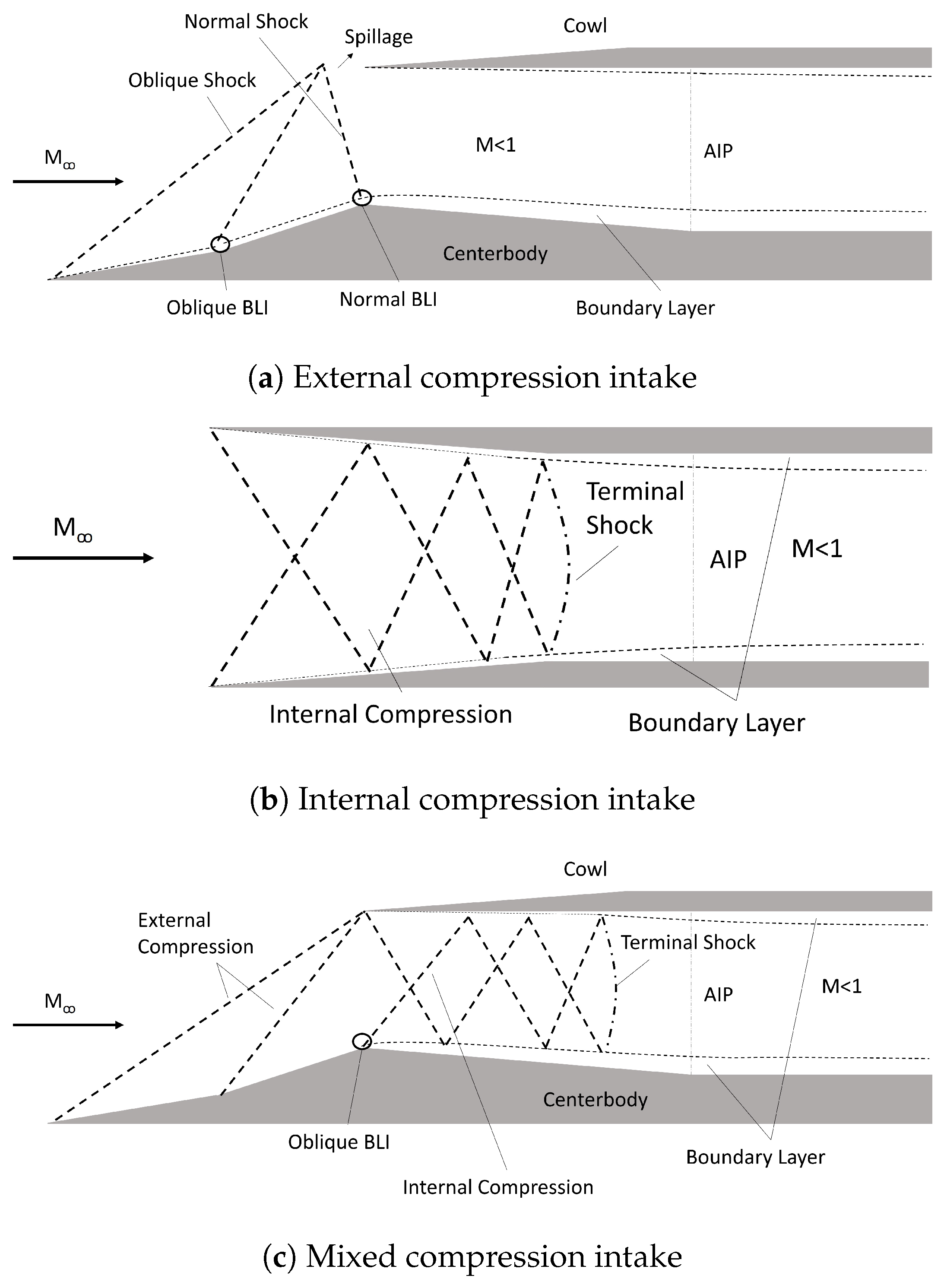
Figure 1. Schematic of a supersonic flow pattern in (a) external, (b) internal, and (c) mixed compression intakes.
Aerospace 11 00075 g001
Figure 2. Operating range of a supersonic, external compression intake. (OS: oblique shock, NS: normal shock, A c : capture flow area, A : freestream flow area).
Aerospace 11 00075 g002
Figure 3. NASA concepts of future supersonic airliners. Source: Images from the internet https://www.nasa.gov/image-article/an-iconic-idea/ (accessed on 1 September 2023). https://www.nasa.gov/centers-and-facilities/armstrong/nasa-marks-continued-progress-on-x-59/ (accessed on 1 September 2023).
Aerospace 11 00075 g003
Figure 4. Shock system and associated flow topologies at buzz as described by (a) Ferri and (b) Dailey criteria. (OS: oblique shock, TP: triple point, BS: bow shock, SS: separation shock, SBLI: shock boundary layer interaction).
Aerospace 11 00075 g004
Figure 5. Flow field oscillations during a buzz cycle at M = 2.0, obtained by Abedy et al. [38] Image reproduced with permission by the Elsevier Masson SAS.
Aerospace 11 00075 g005
Figure 6. Shock system topology in relation to a supersonic entry at two different time instances during a buzz cycle, at (a) t 1 : normal shock most downstream position and (b) t 2 : oblique shock most upstream position, demonstrating the collision between the shear layer, resulting from substantial separation, and the inner surface of the cowl.
Aerospace 11 00075 g006
Figure 7. Effect of the Mach number on the intake performance (Image re-adapted from Ref. [90]).
Aerospace 11 00075 g007
Figure 8. Illustration schematic of the boundary layer bleed through natural ventilation (Image re-adapted from [119]).
Aerospace 11 00075 g008
Figure 9. Time-averaged schlieren images of flow separation controlled by energy discharge under M = 6.13 obtained by Wang et al. [161] (Image reproduced with permission of AIP Publishing, https://doi.org/10.1063/5.0094186 (accessed on 1 September 2023)).
Aerospace 11 00075 g009
Figure 10. Schematic of: (a) normal SBLI for (b) oblique SBLI in a constant area duct (Image re-adapted from [175] for illustration).
Aerospace 11 00075 g010
Figure 11. Schematic diagram of the 3D structure and distribution of the vortex systems [211] (Image reproduced with permission by the authors).
Aerospace 11 00075 g011
Figure 13. Illustration of a distortion simulation test rig concept design [166] (Image reproduced with permission by the authors).
Aerospace 11 00075 g013
Table 3. Summary of key findings on the research of flow control in supersonic flow.
ReferenceResearch TopicMethod (E/N)ModelOnset Mach NumberKey findings
Jagannathan and Johansen [145]Effect of particle injection on Ferri instability and unstartN (2D)External compression2.0Particles promoted the growth of separation and increased buzz frequency, demonstrating the importance of the location where the particle momentum and energy exchange occurs.
Webb et al. [151]Effect of LAFPA on controlling SBLIECompression Ramp2.33LAFPA did not control the SBLI through instability manipulation, but through the interaction between the LAFPA and the upstream boundary layer, which caused an increase to the thickness of the boundary layer displacement
Falempin et al. [155]Effect of plasma discharge on shock configuration at off-design conditionsE and NTwo-dimensional mixed compression intake2.0At off-design conditions, the plasma discharge can increase the air mass flow rate with moderate deposition of power, illustrating the importance on the power deposition. With a further power increase, the MFR decreases due to the shock angle elevation increasing the boundary layer thickness on the compression ramp.
Pham et al. [159]Effect of repetitive laser energy deposition on suppressing instabilities within intake at off-design conditionsEAxisymmetric intake1.92Repetitive energy deposition can reduce the separation length and suppress the shock system oscillation at a deposition frequency of 60 kHz.
Russell et al. [160]Effect of laser energy deposition on improving the intake performance at off-design conditionsEAxisymmetric intake1.92Laser energy deposition with a deposition frequency of 10 kHz is able to reduce the flow separation and, in turn, improve the intake pressure recovery. The laser frequency is a determining factor in maximizing the length of the attached flow. At higher deposition frequencies, the pressure recovery shows a decline.
Table 4. Summary of the key findings on shock train unsteadiness within isolators.
ReferenceResearch TopicMethod (E/N)ModelOnset Mach NumberKey Findings
Hunt and Gamba [171]Origin of shock train’s unsteadinessEIsolator2.0Background waves affect the leading shock. Vortices generated from the shear layer affect the downstream shocks.
Xiong et al. [198]Characterization of self-excited shock train oscillationsERectangular duct3.0The shock train adjusts its moving speed relative to the upstream Mach number to compensate for the fluctuating back pressure.
Wang et al. [204]Characterization of low-frequency unsteadinessE and NIsolator2.94Three oscillation types were observed. Feedback mechanism of the shock train oscillation was related to the propagation of acoustic waves (associated with oscillation Type I), the duct volume effect, and Kantrowitz limits (Type II). Type III oscillation is an independent process dominated by the shock motion.
Jiao et al. [201]Response of the shock train to forcing back pressureN2D inlet- isolator7.0Phase difference between back pressure fluctuation and shock train oscillation, especially for high forcing frequencies, where the phase of the shock train is opposite to the fluctuating back pressure.
Table 5. Summary of the key findings on flow distortion in convoluted intakes.
ReferenceMethod (E/N)GeometryMAIPKey Findings
Chiereghin et al. [224]NH/L = 0.490.39Higher offset configuration gives rise to pressure fluctuations in the central part of the AIP
Gil-Prieto et al. [225]NH/L = 0.49; 0.270.27; 0.60Vertical swirl switching originates from the centerline shear layer. Lateral swirl switching promotes bulk swirl events
Gil-Prieto et al. [24]E (SPIV)H/L = 0.49; 0.270.6Vertical swirl switching promotes streamwise and in-plane velocity fluctuations
McLelland et al. [23]E (TR-PIV)H/L = 0.490.27Greatest contribution to flow unsteadiness in spectral band St = 0.4–0.6
Migliorini et al. [231]E (TR-PIV)H/D i n = 2.440.27Boundary layer orientation of 90 increases the probability of distortion events giving rise to the probability of compatibility issues
Disclaimer/Publisher’s Note: The statements, opinions and data contained in all publications are solely those of the individual author(s) and contributor(s) and not of MDPI and/or the editor(s). MDPI and/or the editor(s) disclaim responsibility for any injury to people or property resulting from any ideas, methods, instructions or products referred to in the content.