Article

Turbopump Parametric Modelling and Reliability Assessment for Reusable Rocket Engine Applications

by
Mateusz T. Gulczyński
1,2,*,
Robson H. S. Hahn
1,
Jan C. Deeken
1,2 and
Michael Oschwald
1,2
1
Institute of Space Propulsion, German Aerospace Center (DLR), 74239 Lampoldshausen, Germany
2
Faculty of Mechanical Engineering, RWTH Aachen University, 52062 Aachen, Germany
*
Author to whom correspondence should be addressed.
Aerospace 2024, 11(10), 808; https://doi.org/10.3390/aerospace11100808
Submission received: 28 August 2024 / Revised: 25 September 2024 / Accepted: 29 September 2024 / Published: 2 October 2024
(This article belongs to the Special Issue Space Propulsion: Advances and Challenges (3rd Volume))

Abstract

:
The development of modern reusable launchers, such as the Themis project with its LOX/LCH4 Prometheus engine, CALLISTO—a reusable VTVL-launcher first-stage demonstrator with a LOX/LH2 RSR2 engine, and SpaceX’s Falcon 9 with its Merlin 1D engine, underscores the need for advanced control algorithms to ensure reliable engine operation. The multi-restart capability of these engines imposes additional requirements for throttling, necessitating an extended controller-validity domain to safely achieve low thrust levels across various operating regimes. This capability also increases the risk of component failure, especially as engine parameters evolve with mission profiles. To address this, our study evaluates the dynamic reliability of reusable rocket engines (RREs) and their subcomponents under different failure modes using multi-physics system-level modelling and simulation, with a particular focus on turbopump components. Transient condition modelling and performance analysis, conducted using EcosimPro-ESPSS software (version 6.4.34), revealed that turbopump components maintain high reliability under nominal conditions, with turbine blades demonstrating significant fatigue life even under varying thermal and mechanical loads. Additionally, the proposed predictive model estimates the remaining useful life of critical components, offering valuable insights for improving the longevity and reliability of turbopumps in reusable rocket engines. This study employs deterministic, thermally dependent structural simulations, with key control objectives including end-state tracking of combustion chamber pressure and mixture ratios and the verification of operational constraints, exemplified by the LUMEN demonstrator engine and the LE-5B-2 engine class.

1. Introduction

Reusable rocket engines (RREs) are attracting significant interest in the aerospace community due to their military and civilian benefits, as well as their potential for cost savings. Unlike traditional engines designed for specific missions, a well-configured RRE can meet various operational needs with a significantly reduced development effort [1,2,3,4]. However, to fully leverage the advantages of reusable liquid rocket engines (LREs), the dependability of the propulsion system across different services becomes a critical factor. This demands additional scrutiny of the most crucial LRE components. Among these, turbopumps play a pivotal role in achieving high specific impulse and thrust-to-weight ratio [5]. As one of the most critical components in LREs, assessing the loading conditions and resulting stresses on turbopump blades is essential for determining engine reusability, particularly concerning high cycle fatigue (HCF) and low cycle fatigue (LCF) margins.
To underscore the importance of turbopump reliability in liquid rocket engines and its impact on reusability potential, the LE-5B-2 engine (Mitsubishi Heavy Industries (MHI), Tokyo, Japan) serves as a pertinent example. This engine, employed in the second stage of the H-IIA/B rocket ((MHI), Tokyo, Japan), faced significant challenges when its firing duration was extended from 2336 to 3160 s in the LE-5B-3 variant. The prolonged operation, combined with multiple mission-duty cycles, resulted in the formation of cracks in the turbine blades and disc-shaft of the fuel turbopump, predominantly attributed to HCF [6]. The engine design featured a partial admission turbine with circumferential blockages intended to optimise blade height and minimise leakage losses; however, this configuration inadvertently destabilised flow and amplified pressure fluctuations, thereby increasing the susceptibility to HCF [6]. Although design revisions in the LE-5B-3 engine ((MHI), Tokyo, Japan), including the implementation of a full admission turbine blade, aimed to mitigate these issues, a comprehensive assessment of turbopump stresses across all operational phases remains essential [7]. Such evaluations are critical, particularly given the demanding conditions of extreme thermo-mechanical strains, rapid start-up sequences, and elevated rotational speeds, which must be integrated into parametric analyses to accurately predict component lifespan and ensure the reusability of the engine [5,8,9,10,11,12].
Research on the combination of model-based design (MBD) with parametric optimisation for critical liquid rocket engine (LRE) components remains unexplored in the current literature. Most studies focus exclusively on either engine cycle modelling or critical component life assessment, with few integrating both. In Ref. [13], the authors present a methodology for LRE cycle modelling combined with fatigue life studies of the combustion chamber, focusing on loads acting on the chamber during engine operation. Ref. [14] evaluates the Vulcain engine using the EcosimPro library, which includes rocket components and auxiliary functions for calculating the physical properties of substances involved in propulsion. The study achieved an error of less than 5% in the model–reality comparison. More recently, Ref. [15] developed a system-level simulation (SLS) model for a reusable LRE with an expander-bleed cycle, comparing static-firing tests with turbopump overhaul inspections. The results showed significant differences in model parameters and alignment with test data during startup and cutoff phases. These studies collectively highlight the limited but growing effort to combine engine cycle modelling with component life assessment, which is essential for reliable performance evaluation and advancing reusable LRE technologies.
This study builds on our previous work, Refs. [5,16], extending the analysis of turbopump reliability and parametric modelling for reusable rocket engines.
This paper is arranged in the following manner:
Section 2 provides an overview of the LUMEN demonstrator and LE-5B-2 engine architectures, set within the context of parametric studies and the development of a generalised turbopump model in the EcosimPro software suite.
Section 3 introduces our “Turbine_Blade_Fatigue” module developed for the EcosimPro environment, detailing the input variables and methodology used to calculate the main stresses and predict the number of cycles to failure, incorporating the modified Goodman–Haigh material failure theory.
Section 4 outlines the transient analysis results for the LUMEN turbopump and the LE-5B-2 class reference engine, focusing on stress analysis and fatigue life estimation under varying operational conditions. A comparison of critical design points using the Goodman–Haigh diagram shows that, despite higher mean stresses, low stress amplitudes lead to high fatigue life in both engines.
Section 5 briefs the main results of this paper, including the effective use of a transient model for estimating turbine blade fatigue life, and highlights the planned future work, such as further model validation, enhancements in analysis, and evaluation of additional factors like multiaxial fatigue, creep, and corrosion.

2. Engine Design and Operations

To validate the presented model, two engines are utilised: the LE-5B-2 class engine, employed as a reference model derived from literature data with estimated hypothetical values, and the Liquid Upper stage deMonstrator ENgine (LUMEN), a breadboard engine in the 25 kN thrust class. The LUMEN engine operates on a mixture of liquid oxygen (LOX) and liquefied natural gas (LNG), with the LNG consisting primarily of 87–89% methane (CH4) and smaller amounts of ethane (C2H6), propane (C3H8), and butane (C4H10). Both the LE-5B2 reference engine and the LUMEN fuel- and oxidiser turbopumps (FTP and OTP) utilise a partial admission turbine blade design. In contrast, the LE-5B-3 employs a full admission turbine blade to mitigate HCF during extended engine operation beyond 2336 s [6]. The engine architecture specifications for both the LUMEN demonstrator and the LE-5B-2 are detailed in Table 1.
Both the LUMEN and LE-5B engines are equipped with fuel and oxidiser turbopumps with partial admission turbine blades. The turbine pressure ratio may be elevated as the gas that drives the turbine is discharged. In the expander bleed (EB) cycle, the energy required to drive the turbine gas is acquired through heat exchange surrounding the combustion chamber. As this cycle is classified as an open-cycle liquid rocket engine, achieving high engine performance requires a low flow rate of the turbine-driven gas. As a result, to generate a significant amount of work output, the turbine in an expander bleed cycle must have a high expansion ratio, exceeding that of closed-cycle liquid rocket engines like staged combustion. Furthermore, with the aim of reducing turbine weight while ensuring a significant shaft power output, it is customary to adopt a high-pressure ratio impulse turbine [18].
With an extensive operational range from 35 bar to 80 bar and a nominal chamber pressure of 60 bar, the LUMEN demonstrator provides a throttling capability between 58% and 133% of nominal thrust [19]. For the LE-5B-2 engine, tests conducted at 60%, 30%, and as low as 3% for idle-mode operation, using only tank-head pressure and without activating the turbine, demonstrate stable functionality over a wide range of conditions [20]. The LE-5B-2 engine employs a regeneratively cooled copper-based system in the nozzle to enhance heat transfer. To mitigate risk in the LUMEN demonstrator (German Aerospace Center (DLR), Lampoldshausen, Germany), two turbopumps are implemented for greater operational flexibility instead of relying on a weight-optimised single-shaft LOX/LNG turbopump. Compared to a flight model, this engine offers improved controllability by utilising six electric valves in place of orifices and traditional pneumatic valves, which typically have slower response times. This enables the engine to maintain the desired operating point, even with varying conditions or component changes. However, the integration of the mixer and turbopumps, driven by heated fuel from regenerative cooling, results in a high degree of coupling, which introduces further complexities for engine control. Figure 1 presents a schematic diagram of both engines.
Figure 1 provides a schematic comparison between the LUMEN FTP and LE-5B-2 engine systems. The LUMEN FTP increases the pressure of the LNG supplied from the test bench interface. A portion of this pressurised LNG is subsequently routed to the Main Combustion Chamber (MCC), controlled by the Fuel Control Valve (FCV). The remaining cryogenic fuel is utilised to cool the combustion chamber walls in a counter-flow configuration. To ensure the necessary injection temperature for the supercritical gaseous fuel, the heated fuel is partially mixed with fuel at a lower temperature, controlled by the Mixer Control Valve (XCV), similar to the method used in the LE-5B-2 engine. The XCV is also employed to control the pressure within the cooling channels, ensuring that the LNG remains in a supercritical state. The excess heated fuel is used to cool the nozzle extension, absorbing additional heat energy that is then utilised to drive both turbopumps. Similarly, the LE-5B-2 engine uses liquid hydrogen (LH2) in an expander-bleed cycle to cool the combustion chamber, with the heated hydrogen driving the turbopumps. This mirrors LUMEN’s use of excess heated LNG for cooling and power generation, ensuring efficient performance under demanding conditions.
In both systems, turbine power is regulated through a series of control valves. In LUMEN, the Turbine Fuel Valve (TFV) manages the FTP, while the Turbine Oxidiser Valve (TOV) controls the OTP. The LE-5B-2 features a similar arrangement of valves to control turbine performance. Additionally, the LOX supplied from the test bench is fed directly into the injector by the Oxidiser Turbo Pump (OTP), which is governed by the Oxidiser Combustion Valve (OCV).
To ensure safe operation, the LUMEN system employs a Turbine Bypass Valve (TBV) to release heated fuel and decelerate the turbopumps when necessary. Similarly, the LE-5B-2 system includes a bypass mechanism to manage fuel release and maintain optimal operating conditions. Furthermore, the Bypass Valve (BPV) in LUMEN regulates mass flow in the cooling channels of the MCC, even when additional fuel mass is not employed for injection or turbine operation. In both engines, the Main Fuel Valve (MFV) and Main Oxidiser Valve (MOV) regulate the initiation and termination of combustion. Precise valve control ensures safe ignition and combustion, facilitated by a torch igniter positioned at the injector head [5,17,19,21,22].

Generalised Turbopump Model in EcosimPro ESPSS for Parametric Study

Most components of the liquid rocket engines operate under extremely harsh conditions, making transient phase operations difficult to model. Start-up and shutdown phases involve complex phenomena critical to engine design and performance evaluation, such as reverse flow in pumps, combustion instabilities, two-phase flows, and turbopumps operating outside their design parameters. To minimise the need for extensive experimental testing and enhance engine reliability, simulations of the ignition and shutdown transient periods are essential [23]. In response to these challenges, our study focused on designing a generalised turbopump model, including the Turbine Blade Fatigue module that we developed. The schematic of the generalised turbopump with a Turbine Blade Fatigue module is shown in Figure 2.
The configuration of the generalised turbopump comprises pipelines, valves, and orifices, with turbine and pump components selected from the ESPSS turbomachinery library, integrated with the Turbine Blade Fatigue module. The piping system simulates the network delivering gaseous nitrogen and LNG for the LUMEN engine and liquid hydrogen for the reference engine. Valve delays are adjusted using additional components tailored to specific requirements. The operation of the turbopump is regulated by custom parameters, performance maps, and dimensionless characteristic curves, aligned with the validated engine specifications and EcosimPro ESPSS models. The generalised turbopump model also accounts for various valve functions, including one that controls turbopump power by adjusting the turbine’s mass flow and pressure ratio and another that regulates the pump’s mass flow to manage the turbopump load. Control over pump pressure and mass flow rate is essential for simulating transient conditions. The flow characteristics describe how the flow coefficient varies with valve position. The Turbine Blade Fatigue module supports multi-physics system-level simulations, providing rapid estimations of turbine blade critical life and failure cycles under different operating conditions, including transient modes. A detailed description of the developed module, along with verification parameters, is presented in the following section.

3. Turbine Blade Fatigue Module

This section details the development of the Turbine Blade Fatigue module, designed for operation in EcosimPro. The blades and vanes of the turbopump are subjected to gas-dynamic loads due to the pressure distribution across their aerofoil surfaces. As the rotational speed increases, the blades also experience significant transverse loads along their curvilinear paths, arising from gyroscopic moments and centrifugal transverse forces [24].
Turbine blade loads can be broadly classified into static and dynamic types, which include fluid flow exerted on the blade profile, mass loads induced by centrifugal forces, and loads generated by the elastic vibrations of the blades and rotor. These loads during operation result in three principal stresses:
  • Tensile stresses due to the rotating blade mass;
  • Bending stresses induced by the medium acting on the blade profile, combined with centrifugal stresses of the rotating blade mass and the blade’s transverse vibrations;
  • Tangential stresses resulting from torsional moments induced by the flowing medium acting on the blade profile, along with torsional moments from the mass forces acting on the blade and the torsional vibrations of the blade’s active section [25].
The analytical framework for calculating the primary loads—rotational forces, gas pressure, and mechanical loads [4,5,10,21,25,26,27,28,29]—is outlined in Appendix A. The essential formulas for the fatigue module are provided in the following subsections and are applicable to load calculations for any partial admission turbine blade. Table 2 summarises the key geometric parameters for the LUMEN turbopump, along with hypothetical values for the LE-5B-2 FTP turbopump, as illustrated in Figure A1 and Figure A2. Using the refined methodology from Ref. [5], along with the parameters in Table 2 and the equations from Appendix A, the Turbine Blade Fatigue Module was developed to estimate the fatigue life of the LUMEN and LE-5B-2 turbopumps.

3.1. Stress Calculation Framework for Partial Admission Turbines

Within the Turbine Blade Fatigue module, the centrifugal stresses at the given radius of the blade are estimated as highlighted in Equation (1):
σ R = γ ω 2 A i x i l   A R 0 + x d x = γ ω 2 2 π R 1 2 R i 2 π
where “ π R 1 2 R i 2 = Φ ” represents a cross-section of the blade aerofoil through which the flowing medium passes.
For the considered partial admission turbine, the gas bending stress is reduced to zero in the non-admission parts of the turbine, where the stress amplitude σ a , 0 D obtained by this 0D method is half of the maximum gas bending stress:
σ a , 0 D = σ g b , m a x , 0 D 2
The mean stress σ m , 0 D obtained by this 0D method is the sum of the centrifugal stress and the stress amplitude:
σ m , 0 D = σ c , 0 D + σ a , 0 D
The main geometric parameters along with operating the conditions applied to the calculations are presented in the following sections [30,31].

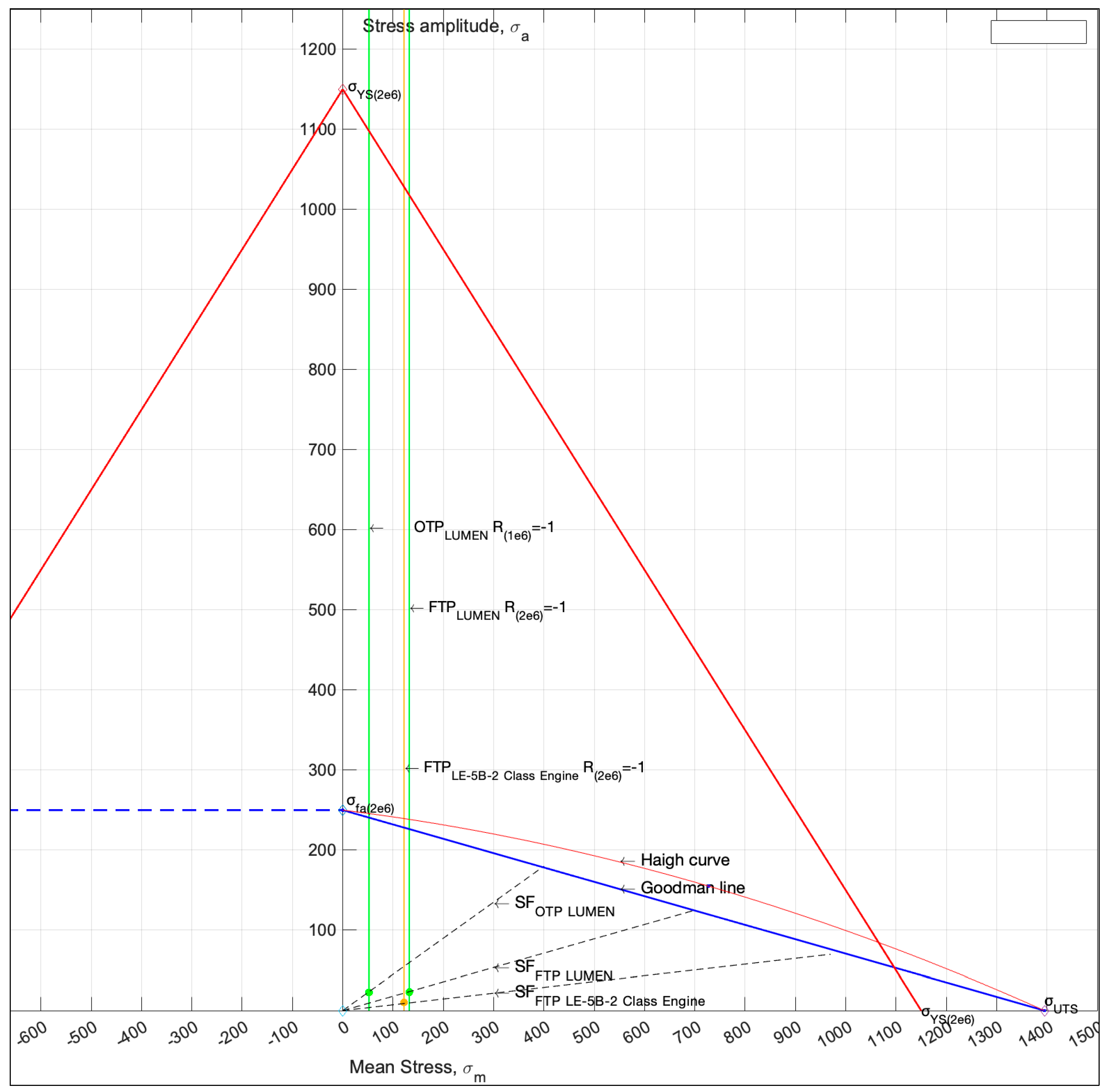
3.2. Fatigue Life Calculations

To evaluate fatigue life at a given stress ratio (alternating and mean stresses) considering material properties (ultimate and endurance strengths), the modified Goodman–Haigh diagram is used, described by the following equation:
σ a σ N f + σ m σ U T S = 1 F S
where σ a —alternating stress; σ m —mean stress; F S —safety factor; σ N f —endurance limit; σ U T S —ultimate tensile strength [32,33].
Furthermore, the following assumptions are made (i.a.w. the Ref. [34]), where the Inconel 718 was studied):
  • in the Goodman equation, the stress amplitude ( σ a ) is normalised by the stress amplitude at the endurance limit ( σ N f ) and for fully reversed conditions, R = −1 to increase accuracy, σ m = 0 ;
  • at a constant load, the mean stress is normalised by the failure stress (R = 1, σ a = 0 ) ;
  • the combination of the Basquin type and the Goodman equation is applied, where:
σ f = A N f B
where “A′ = 7160 MPa”, “B′ = −0.1872”, and “C′ = 1154 MPa” are the fitting parameters as compiled to be fitted in accordance with HCF tests carried out in the specified gas. A modified Goodman equation is then used to determine the number of cycles until failure “ N f ” (as proposed in Ref. [34]):
N f = σ a A 1 σ m C B
The endurance limit is assessed with a Goodman—Haigh diagram.

3.3. Material Properties

The LUMEN turbine blades are made of Inconel 718, and it is similarly assumed that the reference engine’s turbine blades are also fabricated using Inconel 718. As discussed in several studies, e.g., Refs. [34,35,36], the mechanical properties of Inconel 718 vary based on the heat treatment applied. For instance, solution treatment and ageing (ST + A) lead to cyclic softening, whereas direct ageing (DA) results in cyclic hardening at elevated temperatures. In the ST + A condition, Inconel 718 exhibits initial hardening, followed by fatigue softening under ambient temperatures, which has also been observed in other heat-treated variants of the alloy with extended aging [36]. Moreover, the mechanical behaviour of nickel-based superalloys, such as Inconel 718, is highly influenced by their chemical composition and microstructure, including factors such as grain size, γ′/γ″ phase size and distribution, carbide and boride content, and grain boundary characteristics. Inconel 718 is characterised by a face-centred cubic (FCC) γ matrix, which contains the various strengthening phases. The primary strengthening mechanism in this alloy is the metastable γ″ phase, which may transform into the stable δ phase (Ni3Nb) after prolonged exposure to temperatures above 650 °C, resulting in degraded material properties [37].
In this research, the reference engine’s turbine blade material properties were approximated from literature data. The properties of Inconel 718 in GH2 and Argon, up to the endurance limit of around 250 MPa at 2 × 10⁶ cycles (at a mean stress of 500 MPa), were taken from Ref. [34], including values such as fatigue strength, true stress at fracture, and tensile strength. Additionally, the yield strength (YS = 1150 MPa) was derived from Refs. [38,39]. Based on this data, the Goodman–Haigh diagram (Figure 3) was developed.
The stress concentration factor, based on the ratio of the fillet radius to blade thickness, was applied as shown in Figure 4 to account for the transition area between the blade and the disc.
For comparison purposes, the LE-5B-2’s firing duration requirement of 2336 s was set as a boundary condition in the analyses. Based on this firing duration and the rotational speed of the turbopump, the turbine blade’s expected lifespan was estimated at 2 million cycles before failure for both the reference engine and the LUMEN FTP, and 1 million cycles for the LUMEN OTP. To accommodate variations in operating conditions during start-up and shut-down transients, we developed a model in EcosimPro, and the results are detailed in the following section.

4. Results and Discussion

This section presents the results of the transient and critical design point analyses.

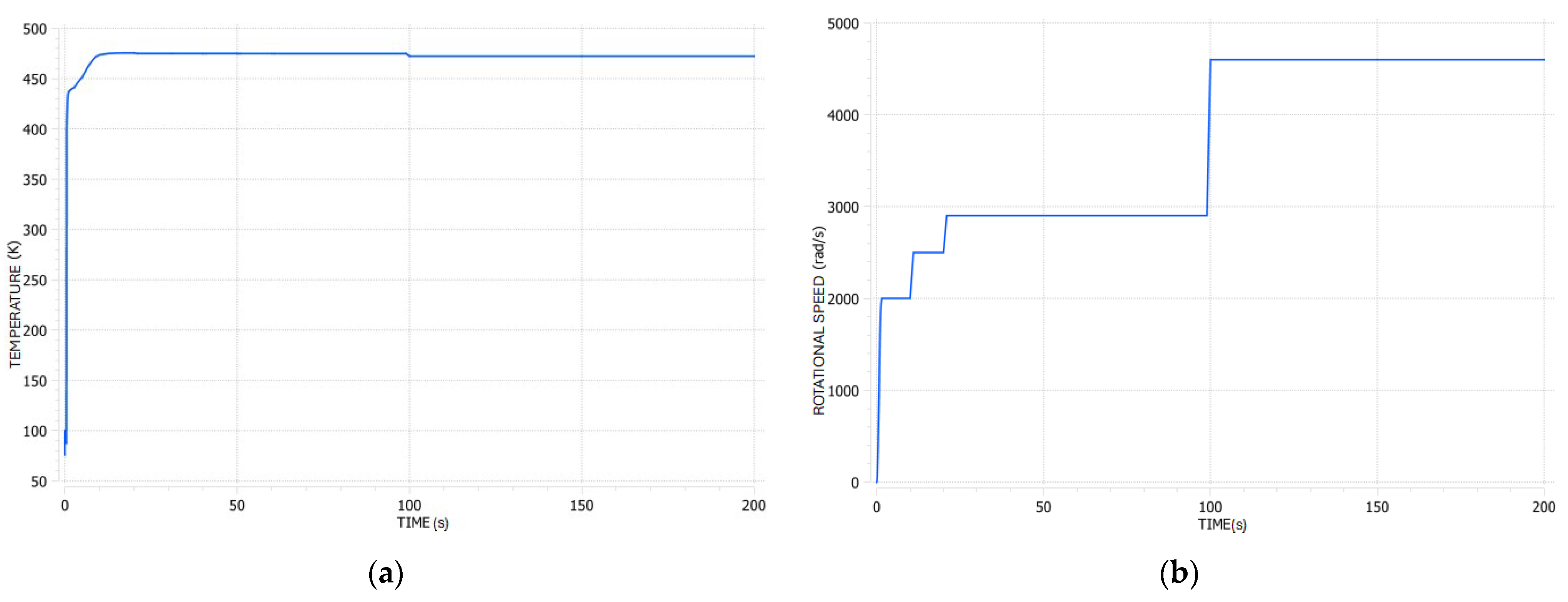
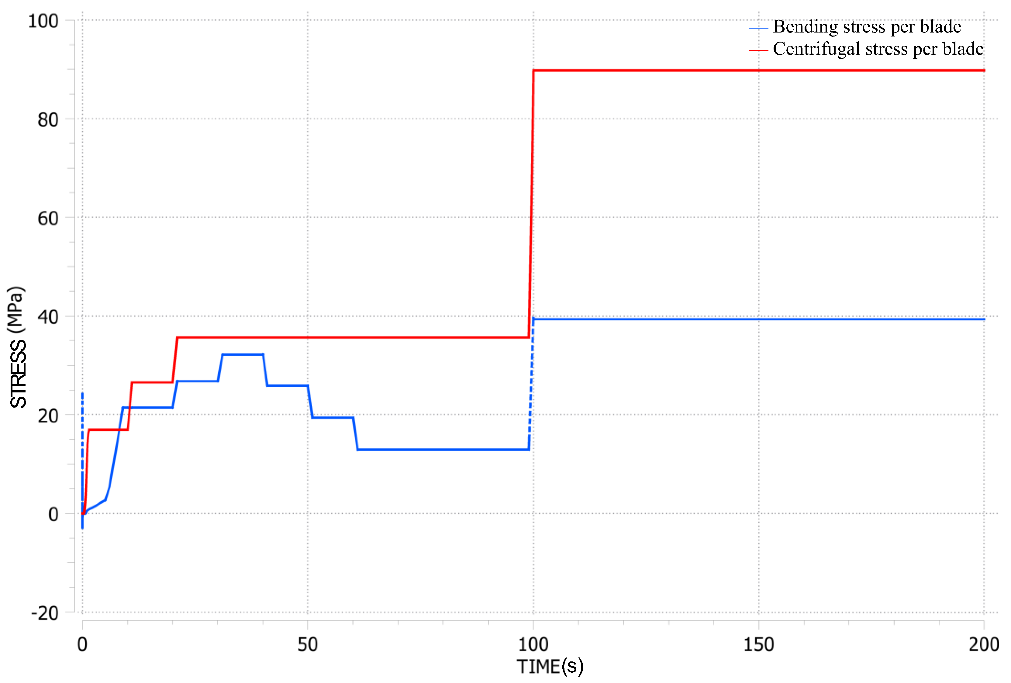
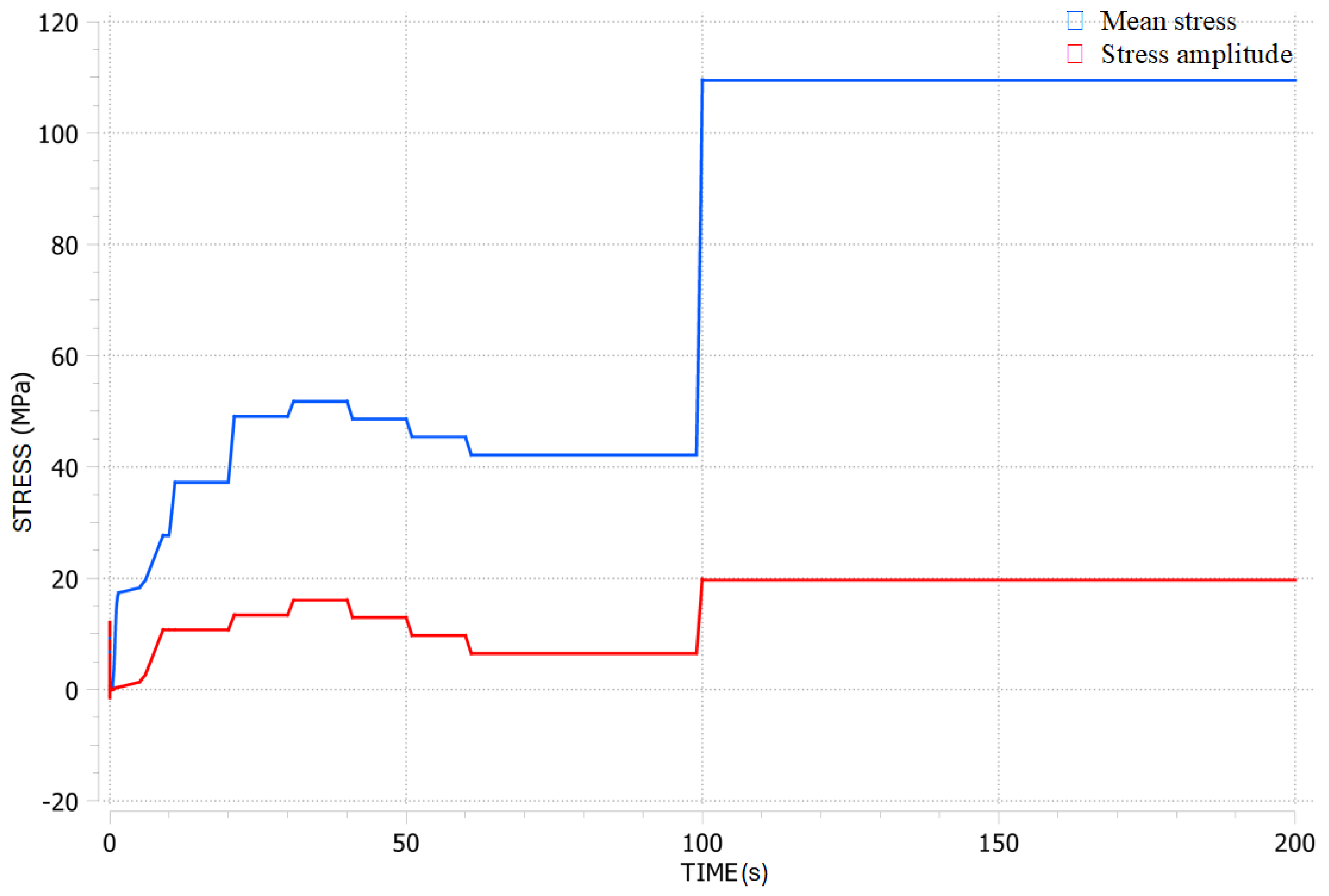
4.1. Transient Analysis Results

Based on the operating conditions of the LUMEN turbopump, the primary parameters of the developed generalised turbopump model, which incorporates the ‘Turbine_Blade_Fatigue’ module, were validated by referring to data from Figure 5, Figure 6 and Figure 7. The validation range includes representative conditions observed during tests at the LUMEN test bench. The mean stress and stress amplitude were estimated based on input parameters and the given operational conditions. The model enables quick predictions of expected stresses and the fatigue life of the turbopump blades. Throughout LUMEN operation, various load points were tested under different conditions over approximately 100 s, with peak loads occurring between 100 and 200 s. These conditions are reflected in the plotted design point on the Goodman–Haigh diagram.
Figure 5 presents an example of the transient analysis results based on the operational envelope of the LUMEN FTP turbopump, incorporating temperature and rotational speed.
In the LUMEN turbopump, friction losses generally result in a reduction of total temperature post-expansion; however, the drop in total outlet temperature remains insignificant across all operational conditions. As a result, the structural temperatures of the stator and rotor remain largely consistent. The operating sequence initiates with cooling of the pump and chilling of the downstream pipeline, followed by turbopump startup until the target operational speed is achieved. Once nominal speed is reached, the turbopump maintains steady operation until shutdown. The primary variations in blade film coefficient and temperature occur during this nominal phase. During the approximately 300-s chill-down phase, the turbine blade’s enthalpy remains relatively stable, as the chill-down process predominantly affects the pump and shaft components. Following chill-down, the shaft region reaches a minimum temperature of 280 K, ensuring the BLISK (blade integrated disc) is not exposed to cryogenic temperatures, thereby preserving the turbine’s structural integrity prior to full operation.
The primary stresses on the blades, including bending and centrifugal stresses, were calculated using the methodology outlined in a previous section. Figure 6 provides an example result from the transient analysis of the LUMEN FTP, utilising the Turbine Blade Fatigue module, with the highest loading conditions observed between 100 and 200 s.
Based on the calculated bending and centrifugal stresses, along with parameters such as rotational speed and mass flow, the amplitude and mean stresses were estimated, as illustrated in Figure 7. For both the LUMEN FTP and the reference engine, the highest mean stress and stress amplitude occur at the nominal operating conditions. The proposed fatigue model assists in evaluating the critical design points and combined fatigue loading.

4.2. Results of Critical Design Point Analysis

Figure 8 illustrates the Goodman–Haigh diagram showing fatigue life results for the LUMEN OTP, FTP, and the reference engine FTP at the design point stress ratio (alternating and mean stresses). As noted earlier, the S-N curve used to determine the evaluated loading conditions and the impact of mean stress on fatigue life, as depicted in the Goodman–Haigh diagram, was sourced from the literature [34].
As highlighted in the Goodman–Haigh diagram, the LUMEN and the reference engine FTP exhibit similar stress levels under nominal operating conditions. Despite the higher mean stress, the stress amplitude remains relatively low—around 23 MPa. Furthermore, the fatigue life is found to be significantly higher than the 2 million cycles estimated as the reference engine’s minimum life for a firing duration of 2336 s.
The calculated stresses for a given design point are presented in Table 3. The estimated factor of safety (SF) for LUMEN OTP and FTP is: SFLUMEN OTP = 7.9, SFLUMEN FTP = 5.2. The safety factor of a reference engine is SFREF Engine FTP = 8.5. Due to the low stress amplitude, the HCF life of the LUMEN and reference engine turbine blades, as predicted by Equation (6), is as high as 17 trillion cycles before failure for both OTP and FTP. The allowable stress amplitude and mean stress will decrease if the number of operating cycles increases, as would be expected in a reusable unit application. In accordance with Ref. [34], and as shown in Figure 3, for Inconel 718 at 1 × 10⁷ cycles, the allowable mean stress and stress amplitude are 200 MPa and 170 MPa, respectively.
In the case of the LE-5B-2 class engine, the allowable stress estimates are considered less conservative due to potential factors such as thermal shock during transient start-up and shutdown phases [41], or the risk of hydrogen embrittlement (HE) when the alloy is exposed to hydrogen gas or hydrogen-containing compounds like hydrogen sulphide (H2S), hydrogen chloride (HCl), or hydrogen bromide (HBr). Such exposure can reduce the metal’s fracture toughness or ductility due to atomic hydrogen infiltration [42]. The embrittlement effect is particularly pronounced in the aged alloy condition, where γ″ and γ′ precipitates are present, compared to the solution-annealed condition [37].
Figure 9 illustrates the typical impact of hydrogen embrittlement (HEE) on the low cycle fatigue (LCF) and high cycle fatigue (HCF) properties of the Inconel 718 superalloy. These tests were conducted at room temperature under a hydrogen pressure of 5 ksi (34.5 MPa). It is important to note that the HCF range in this figure is defined as when the cumulative fatigue life (CTF) exceeds 1 million cycles.

5. Summary and Conclusions

In this work, a transient model was developed using the EcosimPro parametric tool and applied to both the LUMEN demonstrator and the LE-5B-2 class engine, with hypothetical parameters sourced from the literature for the latter. The model integrates the Turbine Blade Fatigue Module, which we specifically designed to estimate the fatigue life of turbopump blades and to interface with the EcosimPro software. The results indicate that the high cycle fatigue life of the LUMEN and reference engine blades is exceptionally long, owing to the low stress amplitude. Within certain limitations, the model serves as a reliable tool for predicting turbine blade fatigue life under user-defined conditions, contributing to the optimisation of blade design and operational safety.
In future work, further validation of the model will require conducting experiments to investigate material properties under low cycle and high cycle fatigue conditions, considering the influence of temperature, manufacturing processes, and exposure to various fuels—particularly since many LUMEN demonstrator tests have been conducted with nonreactive nitrogen. Additionally, enhancements to the transient analysis and damped vibration modelling of turbine blades in the non-admission sections of the turbine are planned. Extended fatigue life analysis will also be pursued, incorporating a damage accumulation method as referenced in studies [43,44] to improve the accuracy of LCF models. Finally, the impact on blade life due to factors such as multiaxial fatigue—combining HCF and LCF—creep, and corrosion will be further evaluated using developed models across different engine applications.

Author Contributions

Conceptualization, M.T.G.; methodology, M.T.G.; software, M.T.G.; validation, M.T.G. and R.H.S.H.; formal analysis, M.T.G.; investigation, M.T.G.; resources, M.T.G., R.H.S.H., J.C.D. and M.O.; data curation, M.T.G. and R.H.S.H.; writing—original draft preparation, M.T.G.; writing—review and editing, M.T.G., J.C.D. and M.O.; visualization, M.T.G.; supervision, J.C.D. and M.O.; project administration, M.T.G., R.H.S.H. and J.C.D.; funding acquisition, M.T.G. and J.C.D. All authors have read and agreed to the published version of the manuscript.

Funding

This research received no external funding.

Data Availability Statement

The original contributions presented in the study are included in the article, further inquiries can be directed to the corresponding author.

Conflicts of Interest

The authors declare no conflicts of interest.

Nomenclature

NomenclatureDescriptionUnitNomenclatureDescriptionUnit
a, bdistances between given axesmNfnumber of cycles until failure-
Across-sectional area of the bladem2nstatnumber driving jets number-
A′, B′, Cfitting parameters for cycle number calculation, MPa for A′ and CMPaPx, Pybending force acting on rotor bladeN
CBselected theoretical centre of gravitymRstress ratio, or radius-
CGcalculated blade’s centre of gravitymRmeanBlade centroid radiusm
cchord lengthmrfilletfillet radius, disc-blade transitionm
d1, d2,
atrapezoid, btrapezoid,
yCG, ytrapezoid,
htrapezoid, Rsemicircle
geometrical parameters to calculate the blade contour and moments of inertia, as highlighted in Figure A2mSxcross-section area of the turbine blade in the inertia calculationsm2
C 1 a axial velocity—stator exhaustm/stmaximum blade thicknessm
C 2 a axial velocity—rotor exhaustm/sxselected distancem
C 1 u tangential velocity—stator exhaustm/sxchordhalf of the chord length ½ “c”m
C 2 u tangential velocity—rotor exhaustm/sβ1r, β2rblade camber angle inputdeg.
Fcentrifugal force acting on rotor bladeNΘadmission degreedeg.
FSsafety factor- ρ fluid density on the bladekg/m3
gacceleration due to gravitym/s2 σ a alternating stressMPa
hblade heightm σ c centrifugal stressMPa
Ix, Iy,
Ixo, Iyo
area moments of inertiam4 σ g b gas bending stressMPa
Ispspecific impulses σ m mean stressMPa
lblade lengthm σ N f endurance limitMPa
mblade masskg σ U T S ultimate tensile strengthMPa
m ˙ mass flow ratekg/sγInconel718densitykg/m3
Mxg, Myg,
Mxo, Myo
bending momentsNm Φ cross-section of the blade aerofoil through which the flowing medium passesm2
nbladesblades number-ωangular velocityrad/s

Appendix A

This appendix presents a comprehensive set of equations for the calculation of tensile loads and bending stresses on turbine blades, induced by centrifugal forces and fluid pressure. The equations address various stress components, including centrifugal forces across blade sections, bending moments, and stresses within the outer layers of the blade. Additionally, geometric parameters and velocity triangles are utilised to calculate moments of inertia and gas-induced bending stresses. The methods outlined are integral to the Turbine Blade Fatigue Module developed in this work, providing accurate estimates of fatigue life under diverse operating conditions [5,16].

Appendix A.1. Tensile Loads on Blades Induced by Centrifugal Forces

For a rotor that spins with an angular velocity “ω”, a differential centrifugal force exerted on a blade segment of length dR is determined as per Equation (A1):
F i = γ ω 2 x i l   A R 0 + x d x
The maximum stress caused by the centrifugal force is calculated for the cross-section at the blade root, at “R0”, using the following equation:
F 0 = γ ω 2 0 l   A R 0 + x d x
As a result, the centrifugal stresses at a specific blade radius are determined as outlined in Equation (A3):
σ R = γ ω 2 A i x i l   A R 0 + x d x = γ ω 2 2 π R 1 2 R i 2 π
where “ π R 1 2 R i 2 = Φ ” represents the cross-sectional area of the blade aerofoil through which the flowing medium passes. Using Equation (A3), the admissible stresses “kr” acting on the blade material are estimated. Depending on the blade material, operating conditions (e.g., flowing medium, temperature), and the admissible stress factor, the elastic deformation of the blade is then calculated:
Δ l = γ ω 2 2 g E R 0 R 1   R 1 2 r i 2 d r i = γ ω 2 6 g E R 1 3 2 3 R o R 1 + R o 3 R 1 3
Finally, the tensile loads on the blade, induced by the centrifugal forces from the rotating blade mass, are calculated using a tabular approach [25].

Appendix A.2. Bending Moments Induced by Fluid Pressure and Centrifugal Loads

The fluid medium passing through the blades generates dynamic force and force induced by the pressure difference between the front and rear parts of the blade. The force components, labelled as “Px” and “Py”, and highlighted in Figure A1, are determined from Equation (A5) with a second flow rate parameter of the working medium “ m ˙ ” and admission degree “Θ”. For short blades, it is common practice to approximate the load intensity at the mean blade radius. Additionally, in the case of an active turbine where p1p2, the expression can be further simplified.
P x = 2 π r i p 1 p 2 2 π r i ϵ ρ c 1 a c 2 a c 1 a P y = 2 π r i ϵ ρ c 1 a c 2 u c 1 u                                                
The axial “c1a, c2a” and tangential “c1u, c2u” velocities at the stator- and rotor-exhaust in the stator frame of rotation are calculated in accordance with a set of equations presented in Ref. [45]). The density of the working fluid acting on the blade “ ρ ” is calculated based on the operating temperature and pressure ranges, along with the specific gas constant. All these factors are critical in transient calculations. A change in axial and tangential velocities, mass flow, rotational speed, etc. influences the fatigue life of the turbine blade. The bending moments are subsequently calculated with Equation (A6):
M x g = z 0 l     P y z z 0 d z = P y ( l z 0 ) 2 2 M y g = z 0 l   P x z z 0 d z = P x ( l z 0 ) 2 2
As in the case of tensile load calculations, the bending moments are calculated using a tabular method, where the blade is sectioned along the height, similarly to what was presented in Figure A1. To calculate the total bending moment about the x-axis in section “i” induced by centrifugal loads, the following Equation (A7) is applied:
M x b e n d i n g = γ g ω 2 R i R 1   A y R i y i R d R M y b e n d i n g = γ g ω 2 R i R 1   A x x i RdR          
Figure A1. Schematic representation of a generic turbine blade, illustrating the blade geometry with parameters including “R0”—root radius, “R1”—tip radius, and “Rmean”—blade centroid radius.
Aerospace 11 00808 g0a1

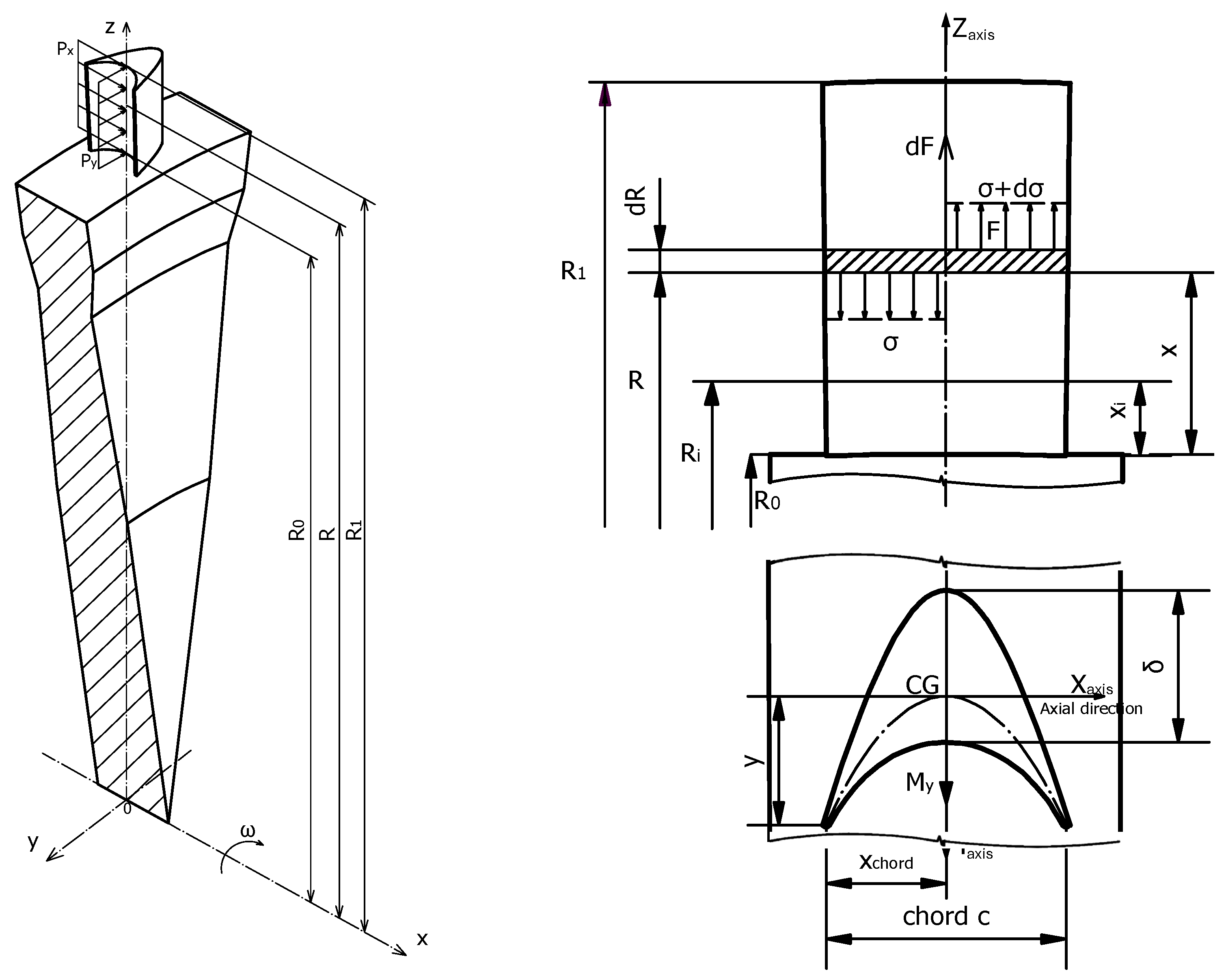
Appendix A.3. Bending Stresses in the Blade’s Outermost Layers

To determine bending stresses in the blade’s outer layers, the centre of gravity and moment of inertia for the blade profile are calculated. Geometrical parameters (Figure A1) and velocity triangles (Figure A2) are used for turbine stress calculation. The blade profile is approximated using geometrical figures, enabling quick stress estimation.
Figure A2. Schematic cross-sections of the LUMEN impulse turbine blade profile, highlighting: (a) blade geometry with central axis system and bending moments acting on the profile; (b) velocity triangles at the inlet and outlet of the blade.
Aerospace 11 00808 g0a2
As shown in Figure A2, the moments of inertia of the LUMEN’s impulse turbine blade are calculated in accordance with Steiner’s parallel axis theorem:
I x = I x 0 A a 2         I y = I y 0 A b 2         I x y = I x 0 y 0 A a b
where “A” is the blade’s cross-sectional area and ‘a’ and ‘b’ are distances between the axes.
The centre of gravity for the LUMEN impulse turbine profile is calculated as follows:
d 1 = y C G y t r a p e z o i d                                                                                     d 2 = y C G y s e m i c i r c l e                                                                                     S x I T B = a + b h 2 d 1 π R 2 2 d 2         A a r e a = a + b h 2 π R 2 2                                                                                         y = S x A a r e a                                                                                                                              
which leads to Equation (A10) for centre of gravity.
C G = y C B + y
The turbine area moments of inertia about the central principal axes are calculated by Equation (A11) for an impulse turbine type.
I x = I x 0 A a 2 = a + 3 b h 3 12 π R 4 8 A a 2                                                                                                                                                                                                       I y = I y 0 A b 2 = a + b a 2 + b 2 h 48 + a + b h 2 ( d 1 + C B ) 2 [ π R 4 8 + π R 2 2 ( d 2 + C B ) 2 ] A b 2
As impulse turbine blades are symmetric, the “x = 0” and “ M x 0 = M x ” and “ M y 0 = M y ” therefore, the bending stress at any arbitrary point of the section is determined by:
σ g a s   b e n d i n g = M x 0 I x 0 y
A change in the angular momentum of the gas in the tangential direction induces a force that generates useful torque and an axial gas bending moment. This leads to tensile stress on the leading and trailing edges, and compressive stress on the suction side of the blade, with the highest stress typically occurring at the leading or trailing edge of the root section [5,10,11,26,46]. The velocity triangle schematic, shown in Figure A2b, is employed for calculating gas bending and centrifugal stresses.

References

  1. Callsen, S.; Stappert, S.; Sippel, M. Study on Future European Winged Reusable Launchers. In Proceedings of the 9th European Conference for Aeronautics and Space Sciences (EUCASS), Lille, Frankreich, 27 June–1 July 2022; pp. 1–14. [Google Scholar]
  2. Lariviere, M.; Kezirian, M.T. Preliminary Safety Assessment of the DLR SpaceLiner Vehicle. J. Space Saf. Eng. 2019, 6, 15–23. [Google Scholar] [CrossRef]
  3. Stappert, S.; Sippel, M.; Bussler, L.; Wilken, J.; Krummen, S. Spaceliner Cabin Escape System Design and Simulation of Emergency Separation from Its Winged Stage. In Proceedings of the 22nd AIAA International Space Planes and Hypersonics Systems and Technologies Conference, Orlando, FL, USA, 17–19 September 2018; pp. 17–19. [Google Scholar] [CrossRef]
  4. Gulczynski, M.T.; Vennitti, A.; Scarlatella, G.; Calabuig, G.J.D.; Blondel-Canepari, L.; Weber, F.; Sarritzu, A.; Bach, C.; Deeken, J.C.; Schmiel, T.; et al. RLV Applications: Challenges and Benefits of Novel Technologies for Sustainable Main Stages. In Proceedings of the International Astronautical Congress, IAC, Dubai, United Arab Emirates, 29 October 2021. [Google Scholar]
  5. Gulczyński, M.T.; Riccius, J.R.; Zametaev, E.B.; Hahn, R.H.; Waxenegger-Wilfing, G.; Deeken, J.C.; Oschwald, M. Turbine Blades for Reusable Liquid Rocket Engines (LRE)—Numerical Fatigue Life Investigation. In Proceedings of the IEEE Aerospace Conference, Big Sky, MT, USA, 4–11 March 2013; IEEE: Piscataway, NJ, USA, 2013. [Google Scholar] [CrossRef]
  6. Terakado, D.; Higashi, K.; Sakaki, K.; Komaru, T.; Suwa, N.; Arimoto, Y.; Ikemoto, A. 2nd Qualification Test Series Results of the Upper Stage Engine LE-5B-3 for H3 Rocket. In Proceedings of the 8th Europe conference for aeronautics and space sciences, Madrid, Spain, 1–4 July 2019; pp. 1–8. [Google Scholar] [CrossRef]
  7. LE-5Bエンジンの信頼性向上燃焼試験の結果について. 2001, Volume 17. Available online: https://www.jaxa.jp/press/nasda/2001/le5b_010321_j.html (accessed on 28 September 2024).
  8. Yoshida, M.; Kimura, T.; Hashimoto, T.; Moriya, S.; Takada, S. Overview of Research and Development Status of Reusable Rocket Engine. In Chemical Rocket Propulsion. Springer Aerospace Technology; Springer: Cham, Switzerland, 2017; pp. 905–931. [Google Scholar] [CrossRef]
  9. Pérez-Roca, S.; Marzat, J.; Piet-Lahanier, H.; Langlois, N.; Farago, F.; Galeotta, M.; Le Gonidec, S. A Survey of Automatic Control Methods for Liquid-Propellant Rocket Engines. Prog. Aerosp. Sci. 2019, 107, 63–84. [Google Scholar] [CrossRef]
  10. Gulczynski, M.T.; Dos Santos Hahn, R.H.; Riccius, J.; Zametaev, E.; Waxenegger-Wilfing, G.; Deeken, J.C.; Oschwald, M. Numerical Turbine Blade Fatigue Life Analysis for Reusable Liquid Rocket Engines (LREs) Applications. In Proceedings of the EUCASS-3AF 2022 9th European Conference for Aerospace Sciences, Lille, France, 27 June–1 July 2022; pp. 1–14. [Google Scholar]
  11. Zhang, W. Failure Characteristics Analysis and Fault Diagnosis for Liquid Rocket Engines; Springer: Berlin/Heidelberg Germany, 2016; ISBN 9783662492543. [Google Scholar]
  12. Dos Santos Hahn, R.H.; Gulczynski, M.T.; Kurudzija, E.; Dresia, K.; Waxenegger-Wilfing, G.; Deeken, J.C. LUMEN Evolution for Lunar Lander Propulsion. In Proceedings of the 2nd International Conference on Flight Vehicles, Aerothermodynamics and Re-entry Missions Engineering (FAR), Heibronn, Germany, 19–23 June 2022. [Google Scholar]
  13. Waxenegger, G.; Riccius, J.; Zametaev, E.; Deeken, J.; Sand, J. Implications of Cycle Variants, Propellant Combinations and Operating Regimes on Fatigue Life Expectancies of Liquid Rocket Engines. In Proceedings of the 7th European Conference for Aeronautics and Space Sciences, Milan, Italy, 3–6 July 2017. [Google Scholar]
  14. Margarit i Bel, N.; Sánchez, M.M. Simulation of a Liquid Rocket Engine. In Proceedings of the 1st Meeting of EcosimPro Users, UNED, Madrid, Spain, 3–4 May 2001. [Google Scholar]
  15. Satoh, D.; Tsutsumi, S.; Hirabayashi, M.; Kawatsu, K.; Kimura, T. Estimating Model Parameters of Liquid Rocket Engine Simulator Using Data Assimilation. Acta Astronaut. 2020, 177, 373–385. [Google Scholar] [CrossRef]
  16. Gulczyński, M.T.; Hahn, R.H.S.; Waxenegger-Wilfing, G.; Deeken, J.C.; Oschwald, M. Parametric Optimization of Turbopump for Reusable Rocket Engine (RRE) Applications. In Proceedings of the 34th International Symposium on Space Technology and Science, Fufkuoka, Japan, 3–9 June 2023; p. 10. [Google Scholar]
  17. Deeken, J.; Oschwald, M.; Schlechtriem, S. Lumen Demonstrator—Project Overview. In Proceedings of the Space Propulsion 2020+1, Virtual, 17–19 March 2021. [Google Scholar]
  18. Kawatsu, K.; Tani, N.; Shimagaki, M.; Uchiumi, M.; Yamanishi, N.; Mitsuhashi, K.; Mizuno, T. Multi Objective Optimization of a Supersonic Axial Turbine Blade Row Shape for a Rocket Engine Turbopump. In Proceedings of the 47th AIAA/ASME/SAE/ASEE Joint Propulsion Conference & Exhibit, San Diego, CA, USA, 31 July–3 August 2011. [Google Scholar] [CrossRef]
  19. Traudt, T.; Börner, M.; Suslov, D.; Hahn, R.H.S.; Saraf, A.M.; Deeken, J.; Hardi, J.; Schlechtriem, S. Liquid Upper Stage Demonstrator Engine (LUMEN): Component Test Results and Project Progress. In Proceedings of the 73rd International Astronautical Congress, Paris, France, 18–22 September 2022. [Google Scholar]
  20. Atsumi, M.; Yoshikawa, K.; Ogawara, A.; Onga, T. Development of the LE-X Engine. Mitsubishi Heavy Ind. Tech. Rev. 2011, 48, 36–41. [Google Scholar]
  21. Dos Santos Hahn, R.H.; Deeken, J.C.; Traudt, T.; Oschwald, M.; Schlechtriem, S.; Negishi, H. LUMEN Turbopump—Preliminary Design of Supersonic Turbine. In Proceedings of the 32nd International Symposium on Space Technology and Science, Fukui, Japan, 15–21 June 2019; pp. 9–10. [Google Scholar]
  22. Adler, A. Design and Robustness Analysis of Neural Network Based Control of Rocket Engine Turbopumps. Master’s Thesis, Julius-Maximilians-Universität Würzburg, Würzburg, Germany, 2022. [Google Scholar]
  23. Matteo, F.D.; Steelant, J. Multi-Disciplinary Propulsion Simulations at Engineering Level by Means of the European Space Propulsion System Simulation ESPSS. In Proceedings of the RTO/AVT/VKI Lecture Series on Fluid Dynamics Associated to Launcher Developers, EN-AVT-206-06, Genesius-Rode, Belgium, 15–17 April 2013; pp. 1–31. [Google Scholar]
  24. Dżygadło, Z.; Łyżwiński, M.; Otyś, J.; Szceciński, S.; Wiatrek, R. Napędy Lotnicze—Zespoły Wirnikowe Silników Turbinowych; Wydawnictwo Komunikacji i Łączności: Sulejówek, Poland, 1982. [Google Scholar]
  25. Lipka, J. Wytrzymalosc Maszyn Wirnikowych; Uklanski, A., Appel, L., Wojdowski, R., Welik, H., Eds.; Wydawnictwo Naukowo-Techniczne Warszawa: Warsaw, Poland, 1967; ISBN T00185554. [Google Scholar]
  26. Гахун, Г.Г. Кoнструкция И Прoектирoвание Жидкoстных Ракетных Двигателей. In Мoсква Машинoстрoение; Рипoл Классик: Moscow, Russia, 1989; Available online: https://books.google.de/books?id=hBr_AgAAQBAJ&pg=PA1&hl=de&source=gbs_selected_pages&cad=1#v=onepage&q&f=false (accessed on 28 September 2024).
  27. National Aeronautics and Space Administration. NASA SP-8110 Liquid Rocket Engine Turbines; NASA: Washington, DC, USA, 1974. Available online: https://ntrs.nasa.gov/api/citations/19740026132/downloads/19740026132.pdf (accessed on 28 September 2024).
  28. Saravanamuttoo, H.I.H.; Cohen, H.; Rogers, G.F.C.; Straznicky, P.V.; Nix, A.C. Gas Turbine Theory SEVENTH EDITION Gas Turbine Theory; Pearson: London, UK, 2017; ISBN 9781292093093. [Google Scholar]
  29. Jack, L.K. Aircraft Engines and Gas Turbines, 2nd ed.; The MIT Press: Cambridge, MA, USA, 1992; ISBN 978-0262534031. [Google Scholar]
  30. Kumar, R.; Kumar, V.S.; Butt, M.M.; Sheikh, N.A.; Khan, S.A.; Afzal, A. Thermo-Mechanical Analysis and Estimation of Turbine Blade Tip Clearance of a Small Gas Turbine Engine under Transient Operating Conditions. Appl. Therm. Eng. 2020, 179, 115700. [Google Scholar] [CrossRef]
  31. Thamizh, R.I.; Velmurugan, R.; Jayagandhan, R. Finite Element Analysis of Metal Matrix Composite Blade. IOP Conf. Ser. Mater. Sci. Eng. 2016, 152, 012008. [Google Scholar] [CrossRef]
  32. Farhat, H. Chapter 5—Typical Service-Induced Damages. In Operation, Maintenance, and Repair of Land-Based Gas Turbines; Farhat, H., Ed.; Elsevier: Amsterdam, The Netherlands, 2021; pp. 107–130. ISBN 978-0-12-821834-1. [Google Scholar]
  33. Farhat, H. Chapter 8—Lifetime Extension: Assessment and Considerations. In Operation, Maintenance, and Repair of Land-Based Gas Turbines; Farhat, H., Ed.; Elsevier: Amsterdam, The Netherlands, 2021; pp. 175–196. ISBN 978-0-12-821834-1. [Google Scholar]
  34. Bruchhausen, M.; Fischer, B.; Ruiz, A.; González, S.; Hähner, P.; Soller, S. Impact of Hydrogen on the High Cycle Fatigue Behaviour of Inconel 718 in Asymmetric Push-Pull Mode at Room Temperature. Int. J. Fatigue 2015, 70, 137–145. [Google Scholar] [CrossRef]
  35. Belan, J. High Frequency Fatigue Test of in 718 Alloy—Microstructure and Fractography Evaluation. Metalurgija 2015, 54, 59–62. [Google Scholar]
  36. Zhong, L.; Hu, H.; Liang, Y.; Huang, C. High Cycle Fatigue Performance of Inconel 718 Alloys with Different Strengths at Room Temperature. Metals 2019, 9, 13. [Google Scholar] [CrossRef]
  37. Iturbe, A.; Giraud, E.; Hormaetxe, E.; Garay, A.; Germain, G.; Ostolaza, K.; Arrazola, P.J. Mechanical Characterization and Modelling of Inconel 718 Material Behavior for Machining Process Assessment. Mater. Sci. Eng. A 2017, 682, 441–453. [Google Scholar] [CrossRef]
  38. Kawagoishi, N.; Chen, Q.; Nisitani, H. Fatigue Strength of Inconel 718 at Elevated Temperatures. Fatigue Fract. Eng. Mater. Struct. 2000, 23, 209–216. [Google Scholar] [CrossRef]
  39. Shao-Hsien, C.; Tsai, K.T. Predictive Analysis for the Thermal Diffusion of the Plasma-Assisted Machining of Superalloy Inconel-718 Based on Exponential Smoothing. Adv. Mater. Sci. Eng. 2018, 2018, 9532394. [Google Scholar] [CrossRef]
  40. Collins, J.A. Failure of Materials in Mechanical Design: Analysis, Prediction, Prevention; Wiley: New York, NY, USA, 1981; ISBN 0471050245. [Google Scholar]
  41. 宇宙開発委員会技術評価部会 H-ⅡAロケットの打上げ前段階における 技術評価について(報告); 2000. Available online: https://www.mext.go.jp/component/b_menu/shingi/giji/__icsFiles/afieldfile/2013/06/10/1335987_001.pdf (accessed on 28 September 2024).
  42. Cottis, R.A. Hydrogen Embrittlement—NASA/TM-2016–218602; NASA: Washington, DC, USA, 2010.
  43. Gulczynski, M.T.; Riccius, J.R.; Waxenegger-Wilfing, G.; Deeken, J.; Oschwald, M. Combustion Chamber Fatigue Life Analysis for Reusable Liquid Rocket Engines (LREs). In Proceedings of the AIAA SCITECH 2023 Forum, National Harbor, MD & Online, 23–27 January 2023; American Institute of Aeronautics and Astronautics: Reston, VA, USA, 2023. [Google Scholar]
  44. Gulczyński, M.T.; Riccius, J.R.; Waxenegger-wilfing, G.; Deeken, J.C.; Oschwald, M. Numerical Fatigue Life Analysis of Combustion Chamber Walls for Future Reusable Liquid Rocket Engines (LREs) Applications. In Proceedings of the Space Propulsion Conference, Estoril, Portugal, 9–13 May 2022; pp. 1–14. [Google Scholar]
  45. Овсянникoв БВ,Б.Б; Б.И.Бoрoвский Теoрия и расчет агрегатoв питания жидкoстных ракетных двигателей. In Машинoстрoение. 1986. Available online: https://www.semanticscholar.org/paper/Теoрия-и-расчет-агрегатoв-питания-жидкoстных-Овсянникoв-Бoрoвский/aaf3eef7159f7df4545c845227bf30967ade271a (accessed on 28 September 2024).
  46. Riccius, J.; Zametaev, E.; Gulczyński, M.T.; Hahn, R.H. Numerical LRE Turbine Blade Fatigue Life Analysis Taking into Account Partial Admission Effects. In Proceedings of the 2nd International Conference on Flight Vehicles, Aerothermodynamics and Re-entry Missions Engineering (FAR), Heilbronn, Germany, 19–23 June 2022. [Google Scholar]
Figure 1. Engine schematics of (a) the LE-5B-2 engine, featuring a mixer design and a partial admission turbine blade cross-section, and (b) the LUMEN demonstrator, showing cross-sections of the LOx and LNG turbopumps (adapted from Refs. [5,6]).
Aerospace 11 00808 g001
Figure 2. Schematic of a generalised turbopump model, developed in the EcosimPro ESPSS environment, incorporating a “Turbine Blade Fatigue” module for critical life assessment.
Aerospace 11 00808 g002
Figure 3. Mechanical properties of Inconel 718 with (a) a Goodman–Haigh diagram for Inconel 718 illustrating 2 × 10⁶ cycles to failure, and (b) top—mean stress vs. number of cycles to failure at a fixed stress amplitude of 218 MPa; bottom—stress amplitude vs. number of cycles to failure at a fixed mean stress of 500 Mpa (adapted from Ref. [34]).
Aerospace 11 00808 g003
Figure 4. Stress–concentration factor as a function of the fillet radius and the blade thickness (adapted from Refs. [10,27,40]).
Aerospace 11 00808 g004
Figure 5. Example of the transient analysis results based on the LUMEN FTP turbopump operational envelope with (a) temperature and (b) rotational speed in rad/s.
Aerospace 11 00808 g005
Figure 6. Transient results for the LUMEN FTP, illustrating bending and centrifugal stresses at the leading and trailing edges of the blades within the operational envelope.
Aerospace 11 00808 g006
Figure 7. Transient fatigue results for the LUMEN FTP: mean and amplitude stresses within the specified operational envelope.
Aerospace 11 00808 g007
Figure 8. Goodman–Haigh diagram for Inconel 718 showing 2 × 10⁶ cycles for the LUMEN FTP and OTP, along with the LE-5B-2 class engine FTP, at the specified design condition point.
Aerospace 11 00808 g008
Figure 9. Effects of hydrogen pressure (34.5 MPa) at room temperature on the HCF of Inconel 718. (source: [42]).
Aerospace 11 00808 g009
Table 1. Comparative specifications of LUMEN demonstrator and LE-5B-2 class engine architectures [6,17].
ParameterLUMENLE-5B-2Unit
Operational cycleexpander bleedexpander bleed-
Nominal thrust25137.2kN
CC mixture ratio3.45-
CC pressure63.58MPa
Specific impulse, Isp-447s
Throttling range58–13360, 30, 3%
Table 2. Input parameters for LUMEN OTP, FTP, and hypothetical LE-5B-2 class engine parameters (marked “*”) derived from literature.
NomenclatureParameterLUMENLE-5B-2 *Unit
Mass of the bladem0.00170.0013kg
Blade centroid radiusRmean0.06350.07875m
Blade driving jets numbernstat(OTP)
nstat(FTP)
3
5
-
44
-
-
Fillet radius (transition between disc and blade)rfillet0.0050.005m
Blade heighth(OTP)
h(FTP)
0.0093
0.0097
-
0.0091
m
m
Blades numbernblades6597-
Blade camber angle input β 1 r β 2 r 69
18
61.5
17
°
°
Blade maximum thicknesstOTP
tFTP
0.00370
0.00406
-
0.00499
m
m
Chord length(OTP&FTP)c0.0090.0075m
Axial velocitystator exhaust C 1 a   ( O T P | F T P ) 246.9|257.7617.6m/s
Axial velocityrotor exhaust C 2 a   ( O T P | F T P ) 201.9|174.1598.9m/s
Tangential velocitystator exhaust C 1 u   ( O T P | F T P ) 875.6|901.21886.8m/s
Tangential velocityrotor exhaust C 2 u ( O T P | F T P ) 406.9|159843.1m/s
Mass flow rate m ˙ 1.0460.491kg/s
Admission degreeΘOTP
ΘFTP
0.229
0.356
-
0.441
-
-
Density of the material γ I n c o n e l 718 81908190kg/m3
Table 3. Worst-case design point of the LUMEN and reference engine TP.
NomenclatureParameterLUMEN OTP|FTPLE-5B-2 Class Reference Engine FTPUnit
Cyclic stress σ c y c l i c 44|4622MPa
Stress amplitude σ a 22|2311MPa
Mean stress σ m 52|132121MPa
Disclaimer/Publisher’s Note: The statements, opinions and data contained in all publications are solely those of the individual author(s) and contributor(s) and not of MDPI and/or the editor(s). MDPI and/or the editor(s) disclaim responsibility for any injury to people or property resulting from any ideas, methods, instructions or products referred to in the content.

