Article

Experimental Study on the Propulsion Performance of Laser Ablation Induced Pulsed Plasma

by
Hang Song
,
Jifei Ye
*,
Ming Wen
,
Haichao Cui
and
Wentao Zhao
*
State Key Laboratory of Laser Propulsion & Application, Department of Aerospace Science and Technology, Space Engineering University, Beijing 101416, China
*
Authors to whom correspondence should be addressed.
Aerospace 2024, 11(12), 1013; https://doi.org/10.3390/aerospace11121013
Submission received: 2 November 2024 / Revised: 27 November 2024 / Accepted: 8 December 2024 / Published: 9 December 2024

Abstract

:
This study investigates the influence of electromagnetic fields on the propulsion performance of laser plasma propulsion. Based on the principle of pulsed plasma thrusters, an electromagnetic field is utilized to accelerate laser plasma, achieving enhanced propulsion performance. This approach represents a novel method for the electromagnetic enhancement of laser propulsion performance. In this paper, pulsed plasma thrusters induced by laser ablation are employed. The generated plasma is subjected to the Lorentz force under the influence of an electromagnetic field to obtain higher speed, thus increasing impulse and specific impulse. An experimental platform for laser-ablation plasma electromagnetic acceleration was constructed to explore the enhancement effect of discharge characteristics and propulsion performance. The results demonstrate that increased laser energy has little effect on discharge characteristics, while the trend of propulsion performance parameters initially rises and then declines. After coupling the electromagnetic field, the propulsion performance is significantly enhanced, with stronger electromagnetic fields yielding more pronounced effects.

1. Introduction

In recent years, the successful execution of space missions such as manned space flight, lunar exploration projects, and Mars exploration, along with the rise of new space technologies such as earth observation, spacecraft formation flight, and deep space exploration, has driven the adoption of micro-nano satellites as the first choice for such missions [1,2]. This necessitates lightweight, compact, and efficient satellite thrusters. The development of propulsion technology with high specific impulse, compact structure, low propellant consumption, and low cost has become imperative [3,4]. Traditional chemical propulsion technologies are limited by their low specific impulse, large mass, and complex structure, whereas the specific impulse of electric propulsion technology offers specific impulses several times or even orders of magnitude greater than chemical propulsion. Furthermore, advancements in mature technology such as Micro Electro Mechanical Systems (MEMS) have accelerated the development of low-cost, small-weight, small-volume, and high-performance micro-nano satellites with shorter development cycles. These micro-nano satellites now face higher demands for orbital maneuvering, precise attitude control, atmospheric drag compensation, and high-precision formation flight [5].
Laser propulsion generates high-temperature, high-density, and powerful plasma through the interaction between a laser beam and material. This plasma forms a backward-oriented jet, thereby generating thrust. In contrast, electric propulsion relies on a power supply to generate an electromagnetic field, which accelerates the plasma to form a high-speed jet and generate thrust, hence the term plasma propulsion [6]. As both propulsion methods involve plasma acceleration, researchers have begun to combine laser propulsion technology and electric propulsion technology [7]. Firstly, plasma is generated by laser propulsion, and then the plasma plume is further accelerated by an electromagnetic field formed through charging to study the propulsion performance of the electromagnetic field on laser-plasma acceleration. Figure 1 illustrates the schematic diagram of the experiment. First of all, a high-voltage power supply is utilized to charge the capacitor, which has an energy storage element to store the voltage. Then, the laser irradiates the surface of polytetrafluoroethylene (PTFE), ionizing it into a certain speed of plasma. The plasma instantly completes a circuit between the anode and cathode plate, discharging the capacitor and generating an electromagnetic field in the discharge chamber, which exerts Lorentz forces on the plasma, accelerating it further and producing stronger thrust [8]. The process comprises two stages. The first stage occurs on the ablative surface of the working medium, where nanosecond laser ablation generates plasma over approximately 100 nanoseconds. The second stage takes place in the discharge chamber, where the Lorentz force generated by the electromagnetic field is applied to the acceleration process of the plasma, which typically lasts several microseconds.
The concept of the acceleration of plasma produced by laser ablation propulsion in electromagnetic fields was first proposed by Japanese scholar Horisawa in 2000. Horisawa believed that the acceleration of laser propulsion in electromagnetic fields could bridge the transition zone between these two propulsion methods, achieving superior performance [9]. In 2002, Horisawa investigated the mechanism of laser plasma generation and acceleration. Studies have shown that particles produced during the initial stage of laser irradiation have a high degree of ionization and are easily accelerated under the action of electrostatic force [10]. Subsequent studies further refined this approach. For instance, in 2004, Horisawa et al. used the Faraday Cup to measure the particle and energy distribution of laser ablation propulsion in electrostatic field acceleration. Their findings revealed superior acceleration performance when positive ions were propelled by a forward electric field. At the same time, the evolution relationship between the electron density and the Debye length of the plasma with time was measured using an electrostatic probe, calculating the optimal installation position of the electrode based on the Debye length [11,12]. In 2007, Horisawa et al. analyzed the impact of laser ignition position on the propulsion performance of laser propulsion in electromagnetic field acceleration, observing better performance when ignition occurred near the cathode [13]. In 2010, Horisawa studied the effects of plate length and spacing on the propulsive performance of laser ablation acceleration by electromagnetic fields composed of parallel plates. Studies have shown that larger discharge channel volumes yield improved results [14]. In 2012, Kobayashi measured the plume of a pulsed plasma thruster with a laser as an auxiliary ignition tool. Through ICCD imaging and flight speed measurement, it was found that when the charging voltage was 2000 V, the plasma speed was 30 km/h, and the speed of the charged particles in the plasma plume was 100 km/h [15]. In 2014, Horisawa et al. investigated the effect of different pulse widths on the propulsive performance of laser ablation propulsion when accelerated in an electromagnetic field. The results demonstrated that nanosecond laser thrusters produced primary impulses approximately 40% higher than those of microsecond lasers [16]. In 2015, Zhang Daixian compared the propulsion performance of Al and PTFE as propellants, observing that the propulsion performance of aluminum as a propellant was better than that of PTFE as a propellant [17]. In 2020, Tan Sheng measured the morphology and plume characteristics of aluminum, copper, polyvinyl chloride, and polyvinyl chloride doped with carbon powder after laser ablation, noting that PVC doped with carbon powder exhibited the smoothest ablation surface and the largest plume expansion rate [18]. In 2021, Duan Buren compared the discharge characteristics and propulsion performance of ammonium nitrate energetic working medium and polytetrafluoroethylene as propellants, showing that the peak discharge current and propulsion performance of ammonium nitrate energetic working medium were higher than that of PTFE [19]. In 2022, Ouyang studied the plume characteristics of PTFE-doped metal oxide and carbon as a working medium and found that the plume-doped graphene working medium displayed the largest expansion rate and the smallest plume divergence angle, and the optimal doping ratio was about 5% [20].
To explore the propulsion performance of laser plasma accelerated by an electromagnetic field, this paper studies the propulsion performance from two aspects: laser energy and electromagnetic field size. Key metrics, including impulse, impulse coupling coefficient, specific impulse, and propulsion efficiency, are measured and compared, respectively, offering insights into the combined laser–electromagnetic propulsion approach.

2. Materials and Methods

2.1. Experimental Apparatus

The electromagnetic field for this experiment was established by affixing two copper plates on the capacitor to form a parallel plate electrode, with PTFE placed between them as the propellant’s working medium (see Figure 2). The top of the plate served as the negative electrode and the bottom plate served as the positive. The positive and negative electrodes of the plate were connected to the high-voltage power supply, with the electrodes connected to horizontally placed capacitors via an insulated switching plate to minimize electromagnetic interference during the experiment. The capacitor size was 2.0 μF ± 10%, the rated voltage was 3000 V, and the rated current was 50 kA. PTFE, chosen for its low cost, high chemical stability, non-toxicity, and environmental friendliness, served as the working medium. The plate and connecting plate are made of copper material for its good electrical conductivity. The length, width, and height of the discharge chamber are 1 cm × 1 cm × 2.5 cm.
The laser used in the experiment had a wavelength of 1064 nm, a pulse width of 8 ns, a working frequency of 1–10 Hz, and a maximum output energy of 900 mJ. The pulse laser energy is adjustable based on the operating voltage (see Figure 3). Before the experiment began, the laser energy was calibrated with a laser energy meter. The input voltage of the high-voltage power supply is 200 V ± 10%, and the output voltage is 500–2500 V.

2.2. Measuring Device

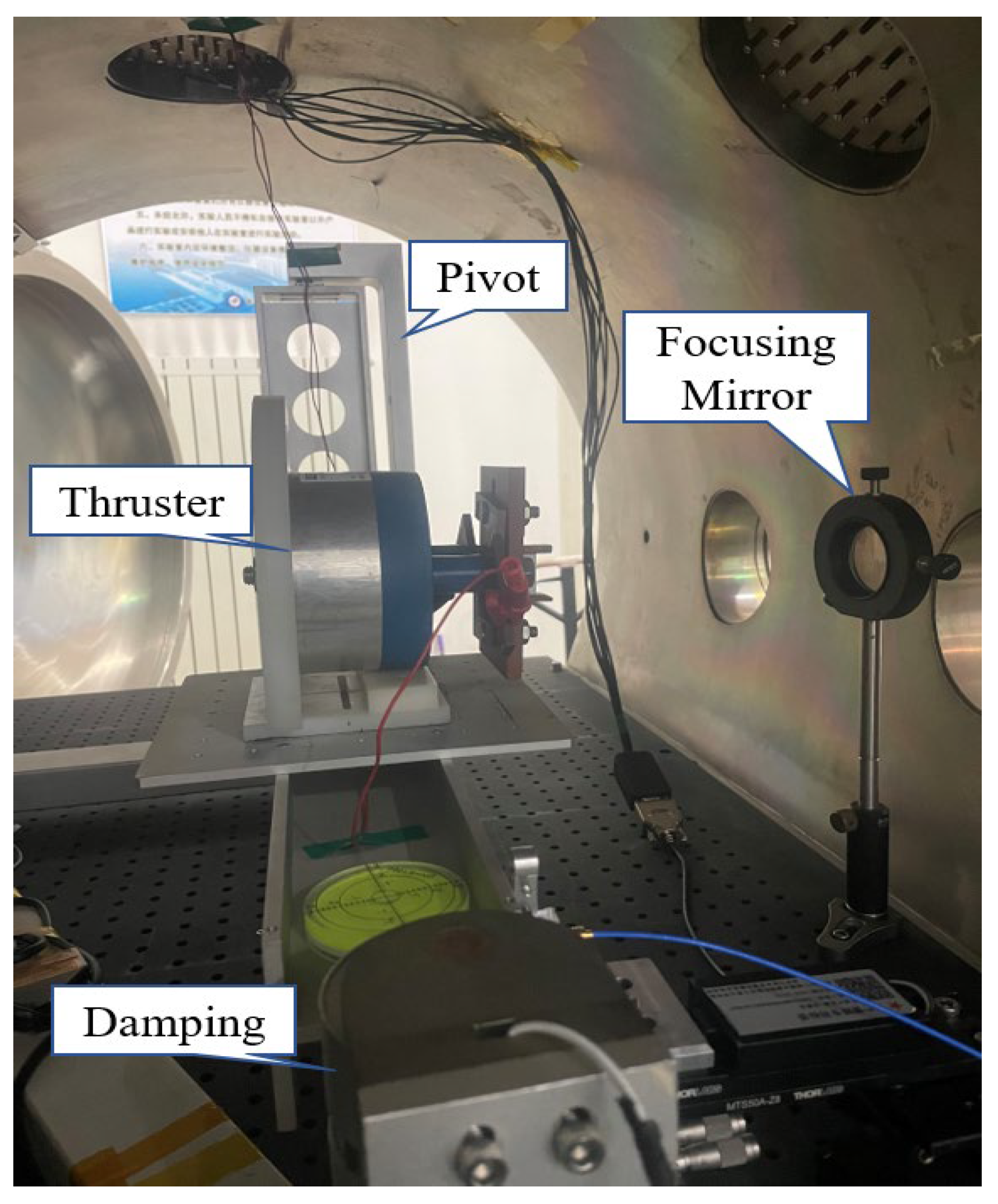
As shown in Figure 4, in the torsion pendulum measurement experiment, the thruster was placed in the vacuum chamber and fixed on the torsion pendulum system. The height of the laser and focusing mirror was controlled by the lifting platform to focus the laser on the surface of the working medium. An electric displacement platform was used to adjust the position of the displacement sensor.
When the laser ablates the working medium, it is equivalent to exerting a force on the torsion pendulum, so that for the torsion pendulum under the action of the pivot recovery force in the horizontal plane for the second order damping vibration, the vibration equation is:
J θ · · + 2 J ς ω n θ · + J ω n 2 θ = M ( t )
where θ is the torsion angle of the torsion pendulum beam, J is the moment of inertia of the beam component, ζ is the damping coefficient of the torsion pendulum system, ωn is the natural vibration frequency, and M(t) is the torque generated by the external force. The relations between the system parameters are as follows:
ω n = ω d 1 ς 2
J = k ω n 2
where k is the torsional stiffness coefficient of the torsion pendulum. The maximum angle obtained by calculation is given by:
θ max = I d J ω d e ς π 1 ς 2
The relationship between the maximum torsion angle and impulse can be obtained. In the experiment, the maximum torsion angle can be measured using the displacement sensor, and the impulse I can be calculated by substituting this value into the formula. Among them, the system parameter damping ratio ζ, the moment of inertia J, and the torsional stiffness coefficient k can be obtained by calibration before the experiment, and the ablative force arm d and the measuring force arm d‘ can be obtained by measurement. The specific values are provided in Table 1.

2.3. Propulsion Performance Parameter

For laser ablation propulsion, the impulse produced during one pulse operation is referred to as the elemental impulse, represented by the symbol I. The working mass symbol consumed is represented by m, and the energy directly acting on the impulse generation process is defined as the propulsion energy, represented by the symbol E. For laser ablation propulsion, energy E denotes the laser energy injected into the working medium. In this experiment, because the laser ablation instantaneously creates a path, the capacitor discharge generates an electromagnetic field to accelerate the plasma twice. Hence, E is the sum of the laser energy El and the capacitor charging energy Ec.
C m = I E l + E c
Specific impulse Isp, the impulse per unit mass of working medium, is defined as:
I s p = I m g 0
The unit of specific impulse is second. In Formula 6, g0 is the local acceleration of gravity.
Energy conversion efficiency η represents the efficiency of converting the total energy consumed during the experiment into kinetic energy. Specifically, it refers to the efficiency of converting both electrical energy and laser energy into kinetic energy, where the laser energy is considered without the electric-optical conversion efficiency. The formula is expressed as:
η = m v 2 2 ( E c + E l ) = 1 2 C m I s p g 0

2.4. Experimental Method

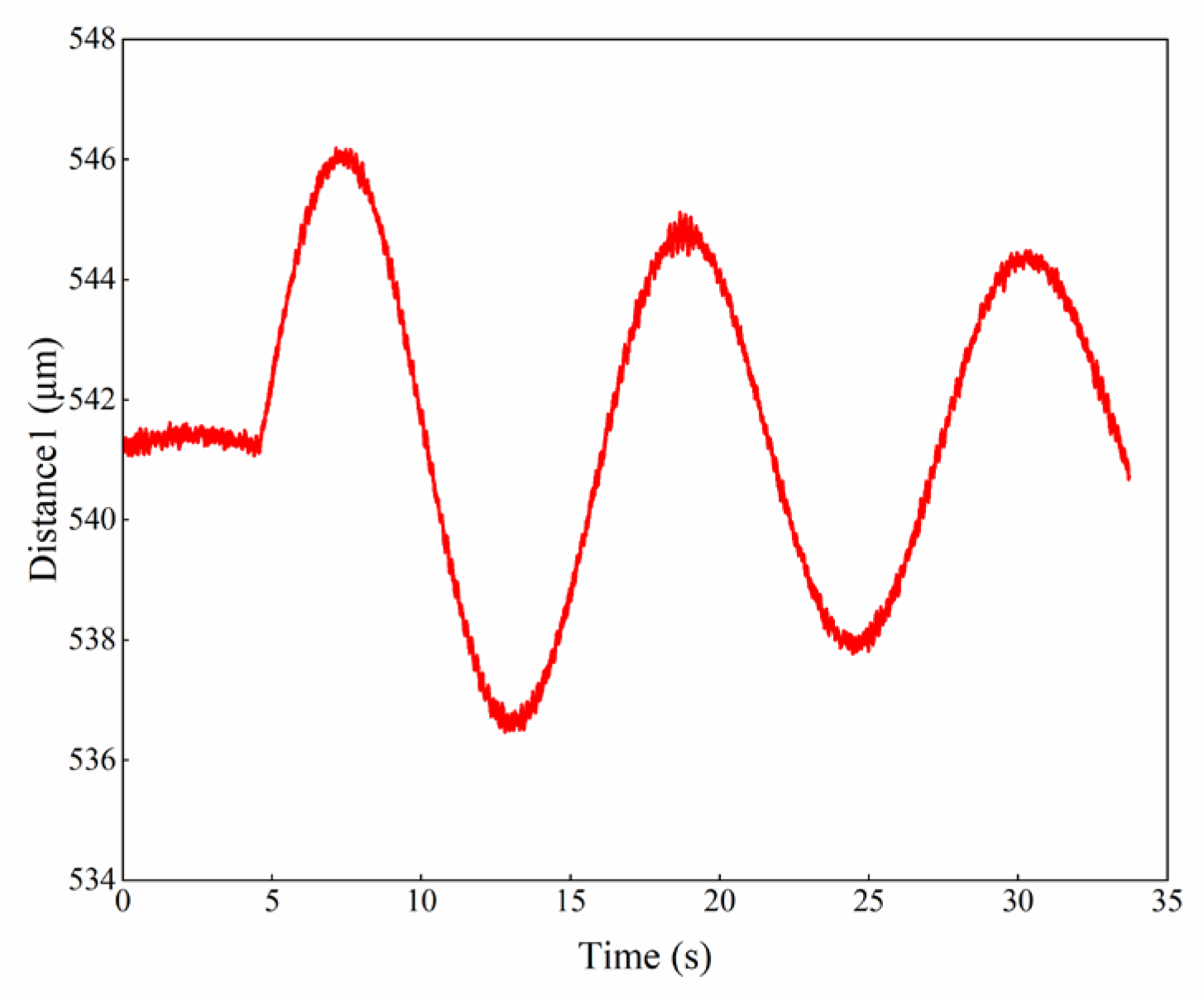
The impulse measurement system primarily consists of a torsion pendulum. The thruster is placed on one end of the torsion pendulum, and the other end is gravity trim. To minimize disturbances, the capacitor is charged with the wiring aligned as closely as possible to the plumb direction, allowing the torsion pendulum to remain balanced vertically and unaffected horizontally, except for the calibration force and the impulse to be measured. Before the experiment starts, the vacuum chamber is evacuated to achieve the required vacuum level of approximately 10−3 Pa. As illustrated in Figure 5, when the laser is radiated at the surface of the working medium, the displacement sensor can measure the displacement of the torsion pendulum. The relative displacement of the torsion pendulum from the equilibrium position to the first peak corresponds to the maximum torsion angle. Due to the existence of electromagnetic damping, the amplitude gradually decreases and returns to the equilibrium position. When the torsion pendulum returned to the equilibrium position, the next experiment was carried out. In this paper, different charging voltages and laser energies are measured to study the propulsion performance of laser ablation propulsion under electromagnetic field acceleration. To prove that the discharge is not accidental, each set of experiments is repeated 5 times.

3. Results

3.1. Discharge Characteristic Study

The capacitance of the capacitor is 2 μF, the laser energy is 358 mJ, 488 mJ, 545 mJ, 602 mJ, 655 mJ, and 730 mJ, respectively, and the charging voltage is 500 V, 1000 V, 1500 V, 2000 V, and 2500 V, respectively. The discharge characteristics, elemental impulse I, and ablative mass ms under different lasers and voltages are measured. The impulse coupling coefficient Cm, specific impulse Isp, and propulsive efficiency η are calculated.
Figure 6 shows the variation curve of discharge current over time under different charging voltages of laser energy E = 730 mJ and E = 358 mJ. From Figure 6a, a higher charging voltage results in a greater peak discharge current. When U = 500 V, the minimum voltage required for discharge is reached, and the corresponding peak discharge current is 100 A. When U = 2500 V, the peak discharge current reaches the maximum of 900 A. The oscillation period remains constant across different voltages but discharge time increases with charging voltage, reaching a maximum of 10 μs. This can be attributed to the fact that the higher the charging voltage, the smaller the equivalent resistance of the generated plasma, and the smaller the discharge period and attenuation. From Figure 6b, different laser energy levels minimally influence plasma discharge characteristics in the electromagnetic field. This suggests that the laser energy is only used to generate the initial plasma and play a role in the ignition of the thruster.

3.2. Propulsion Performance Study

Figure 7 shows the variation curve of the element impulse under different charging voltages and laser energies. The error bar in the figure represents the standard deviation from three parallel tests. From Figure 7a, under different laser energies, its primary impulse increases with the increase in charging voltage. This experimental result is consistent with the changing trend measured by Ouyang in the 2019 experiment [21]. Due to variations in the structure and the parameters of the thruster, the change trend can only be compared qualitatively. When U ≤ 1500 V or U ≥ 2250 V, the laser energy E = 655 mJ corresponding to each voltage produces the maximum element impulse. When U = 2500 V and E = 655 mJ, the maximum element impulse increases to 138.8 μN·s. From Figure 7b, as the charging voltage increases, a larger laser energy results in a higher growth rate of the primary impulse. In addition to the charging voltages U = 1750 V and U = 2000 V, the laser energy corresponding to the maximum value of the element impulse is 655 mJ, so the laser energy E = 655 mJ with the optimal element impulse. This demonstrates that, due to the acceleration effect of the electromagnetic field on laser plasma, the element impulse of laser ablation propulsion (U = 0) increases, and the increase in charging voltage is larger than the increase in laser energy. Therefore, the charging voltage plays a leading role in the plasma acceleration impulse generated by laser ablation.
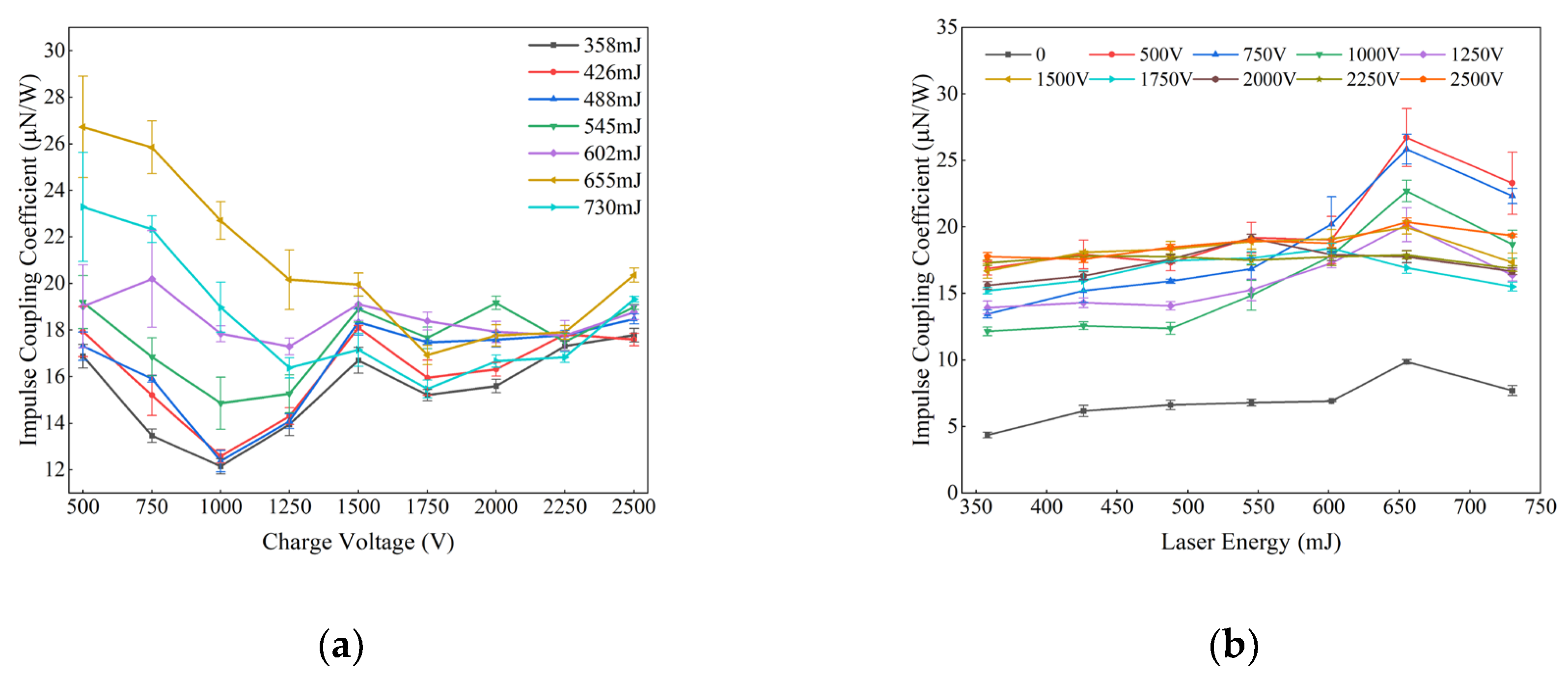
Figure 8 shows the variation curve of the impulse coupling coefficient under different charging voltages and laser energies. According to Formula (5), the impulse coupling coefficient reflects the ability to convert consumed energy into impulse. When calculating this coefficient, both the laser energy and the capacitor discharge energy must be considered. So, the energy consumed is equal to the laser energy plus the capacitor discharge energy. From Figure 8a, it can be observed that as the charging voltage increases, the impulse coupling coefficient initially decreases and then increases but remains smaller than or approaches the value at U = 500 V. When U ≥ 1500 V, the impulse coupling coefficient exhibits an oscillating trend. When U = 500 V, the impulse coupling coefficient reaches the maximum value when the laser energy is 655 mJ and 730 mJ. As the charging voltage increases, when U = 2500 V, the impulse coupling coefficient reaches the maximum value when the laser energy E ≤ 602 mJ. In the upper left corner of the curve, the discharge energy is less than the laser energy at the point where the impulse coupling coefficient reaches a relatively high value. From Figure 8b, the impulse coupling coefficient first increases and then decreases with the rise in laser energy, following the same growth trend of laser ablation propulsion (U = 0). When the electrode is charged with voltage to cause discharge, the impulse coupling coefficient is at least twice that of the uncharged voltage. When the laser energy is 630 mJ and the charging voltage is 500 V, the maximum impulse coupling coefficient reaches 26 μN/W.
Figure 9 shows the variation curves of specific impulses under different charging voltages and laser energies. From Figure 9a, the specific impulse gradually increases with rising charging voltage. When U ≤ 1500 V, the specific impulse of the laser energy of 655 mJ surpasses that of other laser energies. From Figure 9b, under the same charging voltage, the specific impulse first increases and then decreases with the rise in laser energy. When U ≤ 1500 V and U = 2500 V, the specific impulse reaches the maximum value when the laser energy is 655 mJ, and the maximum specific impulse is 568.9 s. A higher charging voltage accelerates the growth rate of specific impulses, indicating enhanced acceleration performance of the electromagnetic field on the laser plasma. Moreover, the higher the charging voltage, the more significant the improvement effect.
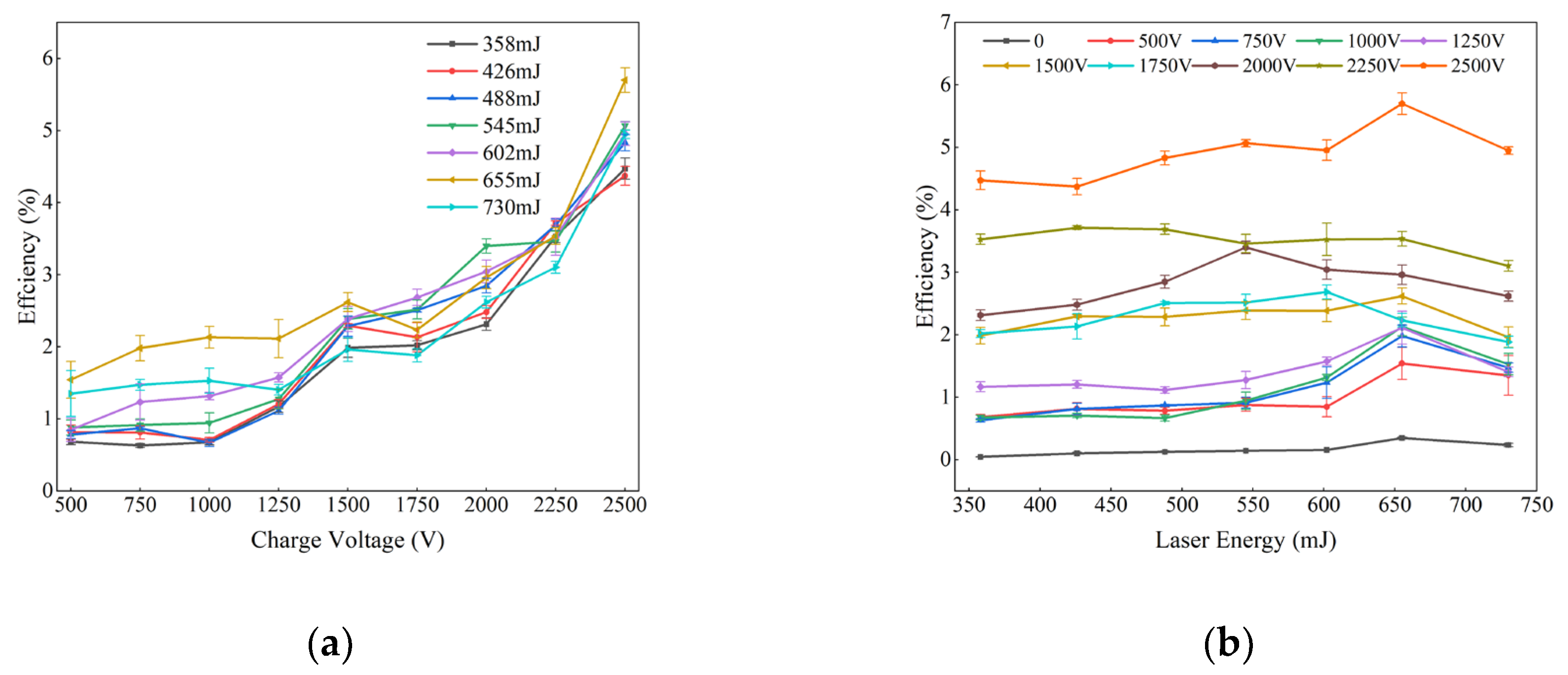
Figure 10 shows the variation curve of efficiency under different charging voltages and laser energies. From Figure 10a, with the increase in charging voltage, the efficiency increases first, decreases appropriately when U = 1750 V, and then increases all the time. When U ≤ 1500 V, the efficiency of the laser energy of 655 mJ outperforms other cases. From Figure 10b, with the increase in laser energy, the propulsion efficiency at different charging voltages first increases and then decreases. When the laser energy is 655 mJ and the charging voltage is 2500 V, the propulsion efficiency reaches a maximum of about 5.8%, coinciding with the peak values of impulse and specific impulse.

4. Conclusions

The paper studies the propulsive performance of pulsed plasma propulsion induced by laser ablation through the difference in laser energy and the electromagnetic field of the initial plasma source. The key conclusions are as follows:
(1)
The study of discharge characteristics indicates that increasing the charging voltage leads to larger peak discharge currents and longer discharge durations. The laser energy has minimal effects on the discharge characteristics, and the laser only acts as a source to generate the initial plasma.
(2)
Through the study of propulsion performance, it is suggested that the size of the electromagnetic field, that is, the charging voltage, significantly improves the propulsion performance of the laser plasma. The higher the voltage, the greater the impulse and specific impulse. When U = 500 V, the maximum impulse is 23.5 μN·s and the maximum specific impulse is 114.1 s. When the charging voltage is increased to U = 2500 V, the maximum impulse is 138.8 μN·s and the maximum specific impulse is 568.9 s, which are increased by 5.9 times and 5 times, respectively.
(3)
Laser energy improves the propulsion performance of plasma in the process of electromagnetic field acceleration. However, in general, the laser energy exerts no obvious effect on the propulsion performance compared to the charging voltage. Under the same charging voltage, impulse and specific impulse first increase and then decrease with the rise in laser energy, reaching the maximum advantage when the laser energy is 655 mJ.
To further explore the thrust mechanism of laser plasma accelerated by electromagnetic fields, future experiments should measure key plasma plume parameters, including electron temperature, electron density, and plasma velocity. The study of the characteristic parameters of plasma plumes is of great significance to the understanding of the formation mechanism of the microphysical phenomena, such as the ablation process, discharge process, and ionization acceleration process. These parameters will form the basis of the next phase of this research.

Author Contributions

Conceptualization, J.Y., W.Z. and H.S.; methodology, all authors; validation, H.S.; formal analysis, H.S.; investigation, H.S.; resources, all authors; data curation, H.S.; writing—original draft preparation, H.S.; writing—review and editing, M.W., J.Y. and W.Z.; visualization, H.S.; supervision, J.Y.; project administration, J.Y.; funding acquisition, H.C. All authors have read and agreed to the published version of the manuscript.

Funding

This research was funded by Haichao Cui, grant number 12402412.

Data Availability Statement

The dataset is available upon request from the authors.

Conflicts of Interest

The authors declare no conflicts of interest.

References

  1. Da-Ren, Y.; Lei, Q.; Wen-Jia, J.; Hui, L. Development and Prospect of Electric Propulsion Technology in China. J. Propuls. Technol. 2020, 41, 1. [Google Scholar]
  2. Sheng, T.; Jian-Jun, W.U.; Yu, Z.; Yu-Qiang, C.; Jian, L.I.; Yang, O.U. Research Progress of Laser-supported Space Micropropulsion Technology. J. Propuls. Technol. 2018, 39, 2415–2428. [Google Scholar]
  3. Levchenko, I.; Xu, S.; Mazouffre, S.; Lev, D.; Pedrini, D.; Goebel, D.; Garrigues, L.; Taccogna, F.; Bazaka, K. Perspectives, Frontiers, and New Horizons for Plasma-based Space Electric Propulsion. Phys. Plasmas 2020, 27, 020601. [Google Scholar] [CrossRef]
  4. Rüdenauer, F.G. Field Emission Devices for Space Applications. Surf. Interface Anal. 2007, 39, 116–122. [Google Scholar] [CrossRef]
  5. Wu, H.; Jiang, Y.; Zhang, Z. Application and Development Trend of Electric Propulsion. J. Propuls. Technol. 2003, 24, 387–394. [Google Scholar]
  6. Zhang, Y. Current Status and Trend of Electric Propulsion Technology Development and Application. J. Propuls. Technol. 2005, 31, 27–36. [Google Scholar]
  7. Berkery, J.; Choueiri, E. Laser Discharge Initiation for Gas-Fed Pulsed Plasma Thrusters. In Proceedings of the 37th AIAA/ASME/SAE/ASEE Joint Propulsion Conference and Exhibit, Salt Lake City, UT, USA, 8–11 July 2001; p. 3897. [Google Scholar]
  8. Furukawa, T.; Takizawa, K.; Kuwahara, D.; Shinohara, S. Study on Electromagnetic Plasma Propulsion Using Rotating Magnetic Field Acceleration Scheme. Phys. Plasmas 2017, 24, 043505. [Google Scholar] [CrossRef]
  9. Horisawa, H.; Kimura, I. Characterization of Novel Laser Particle Accelerators for Space Propulsion. In Proceedings of the 36th AIAA/ASME/SAE/ASEE Joint Propulsion Conference and Exhibit, Las Vegas, NV, USA, 24–28 July 2000; p. 3487. [Google Scholar]
  10. Horisawa, H.; Kimura, I. Fundamental Study on Laser Plasma Accelerator for Propulsion Applications. Vacuum 2002, 65, 389–396. [Google Scholar] [CrossRef]
  11. Horisawa, H.; Kawakami, M.; Igari, A.; Kimura, I. Discharge Characteristics of Laser-Electric Hybrid Thrusters. In Proceedings of the 37th AIAA/ASME/SAE/ASEE Joint Propulsion Conference and Exhibit, Fort Lauderdale, FL, USA, 20–24 June 2004; p. 3937. [Google Scholar]
  12. Horisawa, H.; Igari, A.; Uchida, Y.; Kino, S.; Kimura, I. Electrostatic Acceleration Mode of Laser-Electric Hybrid Thruster. In Proceedings of the 37th AIAA/ASME/SAE/ASEE Joint Propulsion Conference and Exhibit, Tucson, AZ, USA, 10–13 July 2005; p. 3697. [Google Scholar]
  13. Ayabe, T.; Horisawa, H.; Funaki, I.; Kimura, I. Rectangular Laser-Electromagnetic Hybrid Pulsed Plasma Thruster. In Proceedings of the 30th International Electric Propulsion Conference, Florence, Italy, 17–20 September 2007; p. 58. [Google Scholar]
  14. Shinohara, T.; Horisawa, H.; Baba, M.; Tei, K. High Specific Impulse Mode of Pulsed Laser Electromagnetic Hybrid Accelerator for Space Propulsion Applications. In Proceedings of the AIP Conference, Santa Fe, NM, USA, 18–22 April 2010; Volume 1278, pp. 191–199. [Google Scholar]
  15. Kobayashi, H.; Horisawa, H.; Funaki, I. A Plasma Behavior Analysis of a Laser-Assisted Pulsed Plasma Thruster. In Proceedings of the 48th AIAA/ASME/SAE/ASEE Joint Propulsion Conference and Exhibit, Atlanta, GA, USA; 2012; p. 4281. [Google Scholar]
  16. Hosokawa, H.; Yamada, O.; Kobayashi, H.; Horisawa, H. Characterization and Improvement of a Laser-Assisted Pulsed Plasma Thruster. Aerospace 2014, 12, 25–29. [Google Scholar] [CrossRef] [PubMed]
  17. Zhang, Y.; Zhang, D.; Wu, J.; He, Z.; Zhang, H. A Novel Laser Ablation Plasma Thruster with Electromagnetic Acceleration. Acta Astronaut. 2016, 127, 438–447. [Google Scholar] [CrossRef]
  18. Tan, S.; Wang, M.; Wu, J.; Zhang, Y.; Li, J. A Study on the Plasma Plume Expansion Dynamics of Nanosecond Laser Ablating Al/PTFE. Energies 2020, 13, 3321. [Google Scholar] [CrossRef]
  19. Duan, B.; Zhang, H.; Hua, Z.; Wu, L.; Bao, Z.; Guo, N.; Ye, Y.; Shen, R. Impulse and Electric Charge Characteristics of Chemical Propellant under Pulsed Laser Irradiation. Vacuum 2021, 192, 110419. [Google Scholar] [CrossRef]
  20. Ou, Y.; Wu, J.; Zhang, Y.; Li, J.; Zhao, Y. Plume Characteristics of Polymeric Material Doped with Different Metal Particles under Pulsed Laser Irradiation. Opt. Laser Technol. 2022, 152, 108132. [Google Scholar] [CrossRef]
  21. Ou, Y.; Wu, J.; Du, X.; Zhang, H.; He, Z. Experimental Investigation on Characteristics of Pulsed Plasma Thrusters with the Propellant Samples of Modified PTFE filled Si, Al and Al2O3. Vacuum 2019, 165, 163–171. [Google Scholar] [CrossRef]
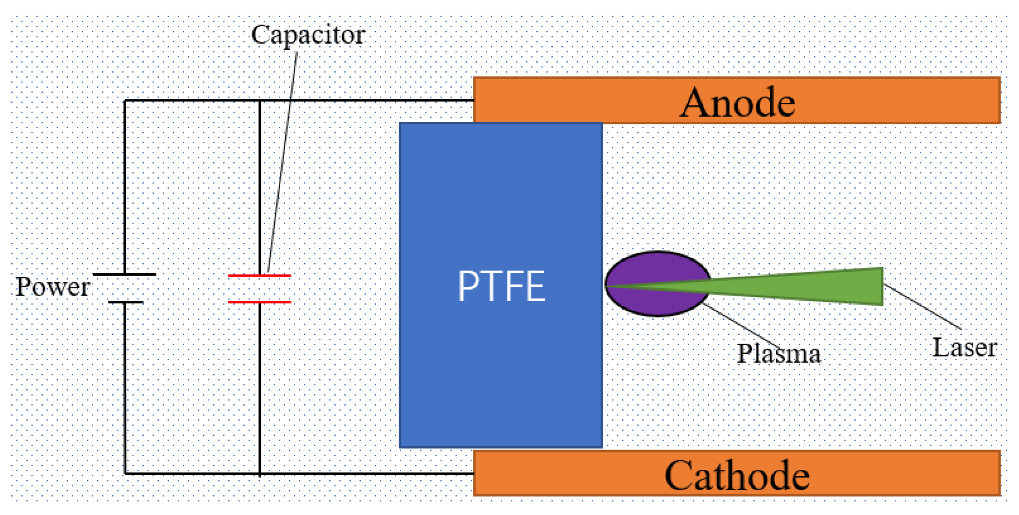
Figure 1. Schematic diagram.
Aerospace 11 01013 g001
Figure 2. Schematic diagram of the experimental apparatus.
Aerospace 11 01013 g002
Figure 3. Laser (left) and high-voltage power supply (right).
Aerospace 11 01013 g003
Figure 4. Physical diagram of the micro impulse measuring device based on the torsion pendulum test bench.
Aerospace 11 01013 g004
Figure 5. Torsion pendulum displacement change curve.
Aerospace 11 01013 g005
Figure 6. Discharge current change curve: (a) the laser energy E = 730 mJ; (b) the laser energy E = 358 mJ.
Aerospace 11 01013 g006
Figure 7. (a) Impulse change curve with charging voltage; (b) impulse change curve with laser energy.
Aerospace 11 01013 g007
Figure 8. (a) Impulse coefficient change curve with charging voltage; (b) impulse coefficient change curve with laser energy.
Aerospace 11 01013 g008
Figure 9. (a) Specific impulse change curve with charging voltage; (b) specific impulse change curve with laser energy.
Aerospace 11 01013 g009
Figure 10. (a) Efficiency change curve with charging voltage; (b) efficiency change curve with laser energy.
Aerospace 11 01013 g010
Table 1. Calibration results of the system parameters of the torsion pendulum device.
System ParameterNumerical Value
Measuring force arm d (mm)630
Ablation force arm d (mm)364
Natural frequency ωn (rad/s)0.6107
Damping ratio ζ0.1379
Moment of inertia J (kg·m2)1.2332
Disclaimer/Publisher’s Note: The statements, opinions and data contained in all publications are solely those of the individual author(s) and contributor(s) and not of MDPI and/or the editor(s). MDPI and/or the editor(s) disclaim responsibility for any injury to people or property resulting from any ideas, methods, instructions or products referred to in the content.