Article

Characterization of a Solar Sail Membrane for Abaqus-Based Simulations

Department of Civil and Industrial Engineering, University of Pisa, I-56122 Pisa, Italy
*
Author to whom correspondence should be addressed.
Aerospace 2024, 11(2), 151; https://doi.org/10.3390/aerospace11020151
Submission received: 18 January 2024 / Revised: 7 February 2024 / Accepted: 12 February 2024 / Published: 14 February 2024
(This article belongs to the Section Astronautics & Space Science)

Abstract

:
Photonic solar sails are a class of advanced propellantless propulsion systems that use thin, large, lightweight membranes to convert the momentum of light from the Sun into thrust for space navigation. The conceptually simple nature of such a fascinating propulsion system requires, however, advances in materials, packaging, deployment, and control of a very large space structure. In this context, the finite element method (FEM), implemented in a robust and flexible software such as the commercial software Abaqus, represents a fundamental instrument to progress with the practical study of this promising propulsion system concept. In particular, in a typical (medium-size) square solar sail design process, the FEM-based analyses are used to better understand fundamental aspects of structural design, such as, for example, membrane pre-tensioning, deformations induced by Solar Radiation Pressure (SRP), and the buckling of reinforcing booms. The aim of this study is to describe an effective procedure to model a classical square solar sail structure into a typical commercial software for finite element analysis, such as the well-known suite Abaqus. In particular, we compare various membrane pre-tensioning techniques (useful for increasing the membrane’s bending stiffness) and describe possible approaches to applying the SRP-induced load in a realistic way. Additionally, the flexibility of the structure under the solar sail loads and the criticality of section shape and boom size are taken into account, with particular regard to the problem of structural instability. In this context, performance and critical issues of different structural solutions are discussed and compared, allowing an improvement in the preliminary design phase of solar sails to be obtained.

1. Introduction

A solar sail is a propellantless propulsion system for space applications [1,2] that converts Solar Radiation Pressure (SRP) into thrust by means of a large, thin, lightweight membrane covered by a highly reflective, metalized film [3,4]. This fascinating propulsion concept remained without an effective test in space for decades, until the launch of the successful Japanese IKAROS experimental spacecraft in May 2010 [5,6]; this launch demonstrated the practical feasibility of the solar sail technology in a typical interplanetary mission scenario [7,8].
With the recent advancement of solar sail technology, interest among the scientific community is increasingly focused on addressing the practical problem of designing the structures of small- and medium-sized solar sails [9,10,11]. In this context, an important problem usually faced by solar sail designers during the preliminary design phase of such a large spacecraft structure [12] is the characterization of both the membrane reflective film [13,14] and the long, slender, stiffening booms [15,16,17]. In fact, during this important phase of the spacecraft design, designers are asked to analyze a series of different configurations [18] through complex numerical simulations in order to evaluate the characteristic performance parameters of the solar sail to be used in the classical trajectory analysis [19,20]. A noteworthy example is offered by the project supported by the Italian Space Agency on the development of solar photonic propulsion; here, the Helianthus mission was chosen as a case study [17,21,22]. In particular, the proposed mission was to maintain an artificial L 1 -type equilibrium point in the Sun–Earth gravitational field by means of a square solar sail; the attitude of this should have been actuated by electrochromic devices, which change their optical properties in response to an electric input, thus generating suitable control torques [23,24]. In that context, a sliding mode controller was first proposed to commute the activation state of the electrochromic devices, with the assumption that the solar sail behaves like a perfectly rigid body [21]. Then, the predicted spacecraft dynamics were validated by performing an accurate structural analysis of the solar sail under operating conditions through a numerical (i.e., finite-element-based) approach [17].
Bearing in mind the lessons learned during the preliminary design phase of the Helianthus solar sail spacecraft [17,21], the aim of this paper is to describe an effective procedure to model a classical square solar sail structure into a typical commercial software for finite element analysis, such as the well-known suite Abaqus [25,26,27]. In particular, the focus of this work is to discuss an effective modeling technique to numerically reproduce the behavior of a classical solar sail reflective membrane when impinged by solar rays. Indeed, the structural response of a solar-sail-based spacecraft is affected by a strong non-linearity of the geometrical nature, which is unavoidable when a transversal load acts on a large and very thin membrane stiffened by few (highly slender) booms [28,29].
In particular, this work uses the classical approach of pre-tensioning the membrane to increase its bending stiffness, and various modeling techniques that introduce such a pre-stress state are described and compared. Then, possible approaches are described to apply the SRP-induced load in a realistic way, that is, as the result of the combined action of the photons that are incident on the sail membrane surface and reflected by it. Moreover, the effects of the intrinsic flexibility of the structure under the solar sail load are taken into account. Finally, the criticality of the section shape and size of the booms is shown, with particular attention to the problem of the classical structural instability.
The paper is organized as follows. Section 2 is dedicated to the description of the geometric model and the applied loads. In particular, starting from the representation of the analyzed configurations (i.e., the monolithic configuration and the one with four triangular sectors), Section 2 provides details about dimensions and materials, finite element modeling techniques, and the application of loads—both pre-tensioning and those due to SRP. The problem of boom buckling is also mentioned in the last paragraph of Section 2. Section 3 illustrates the results of the numerical simulations in terms of stress field induced by tensile pre-tensioning, the out-of-plane displacement field induced by SRP, and the boom buckling modes. Finally, Section 4 draws our concluding remarks.

2. Materials and Methods

A typical square solar sail can be made according to different configurations [30], which can in turn be grouped into two macro categories: (i) sail divided in four triangular sectors (see Figure 1); and (ii) monolithic sail (see Figure 2).
The sector-based solar sail can only be supported by a cruciform beam, while the monolithic configuration can also be stiffened via a perimeter frame. In all cases, the connection between the membrane and the stiffening elements can vary both based on the number of attachment points and type of connection itself. In particular, the joining can be mediated by cables of not-negligible length or by means of shorter and stiffer elements, such as extensional springs attached to grommets. The type of element that materializes the joint anyway depends on the technique for the sail pre-tensioning, as will be discussed in Section 2.3. This study deals with the case of cruciform booms connected to a sector sail in five attachment points as sketched in Figure 1, and to the monolithic one in only four locations as shown in Figure 2. Finally, the case of a frame boom attached by means of cables to a monolithic sail in four points is considered.

2.1. Dimensions and Constituent Materials

The reference sail membrane is made of Kapton, aluminized on the reflective side, with total thickness of 2.5 µm. The reference sail side is 20   m , so that the solar sail surface (i.e., the exposed area of the sail membrane) area is 400   m 2 , regardless of whether it is divided into sectors or not. Note that the selected side value is consistent with a medium-size solar sail, which can theoretically be used in a wide range of mission scenarios, such as the maintenance of displaced non-Keplerian orbits, the fulfillment of interplanetary transfers, the station keeping in heliostationary points, or the generation of artificial Lagrangian points. Then, the actual performance of a solar sail propulsion system also depends on the total spacecraft mass, which affects (together with the sail size) the propulsive acceleration magnitude at the reference distance of one astronomical unit from the Sun. The lengths of the arms of the cruciform boom are variable with the type of connection to the membrane. In particular, a length of 14.87   m (or 14.14   m ) for the joining with (or without) cables has been assumed.
The frame boom is square and has a total length of 82   m . The boom section has a thin circular pipe shape with 200   mm radius and 0.15   mm thickness, while the boom material is a composite with high-modulus spread–tow carbon fibers. The cables, when present, are made of Kevlar, with circular cross-section of 7.85 × 10 7   m 2 and a length of 0.56   m (or 0.25   m ) if they are external (or internal). Finally, the payload is simulated as a single concentrated mass of 7.6   kg at the center of the cruciform boom, or divided in four equal masses at the corners of the frame boom.
The material properties used in the numerical simulation of the (whole) spacecraft dynamics are summarized in Table 1, while Table 2 shows the properties of composite material used in the detailed shell model to study the boom structural instability. In particular, the last data represent the engineering constants of a laminate with symmetrical lay-up 0°/±45°/±45°/0°, made of two external plies of unidirectional and two internal plies of spread–tow fabric.

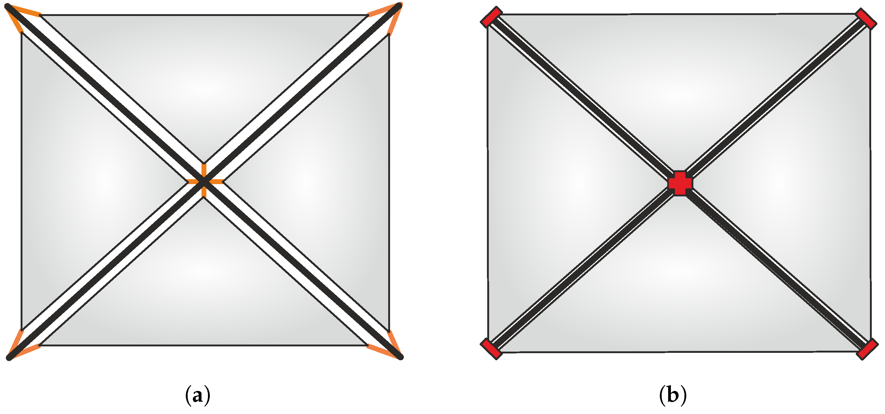
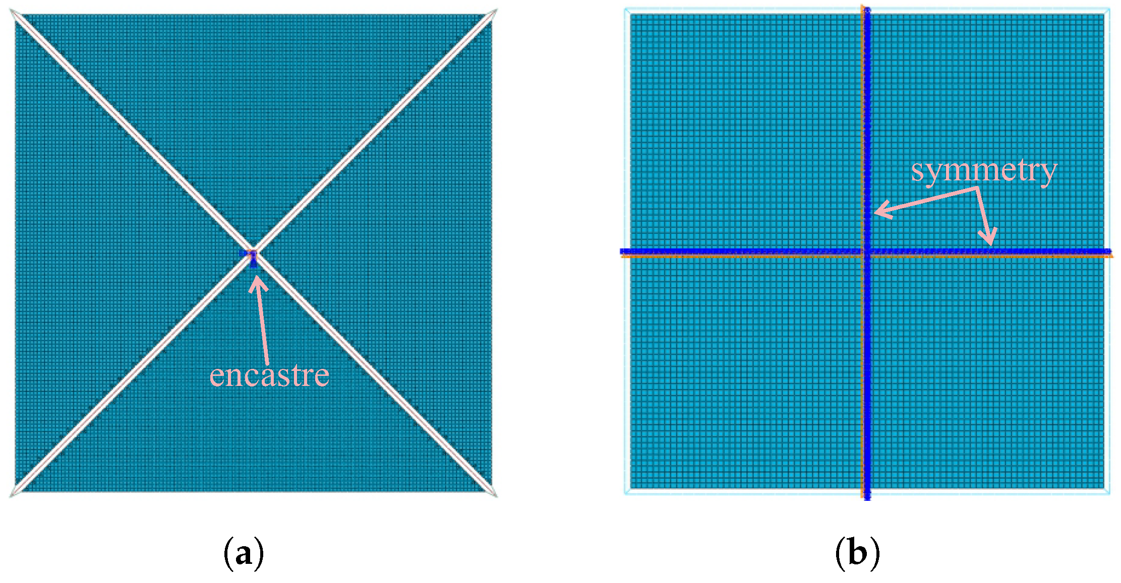
2.2. Finite Element Modeling Techniques

The commercial software Abaqus 2022 was used to perform the numerical simulations of the square solar sail structure. In all the configurations analyzed, the membrane, booms, and cables are modeled with fully integrated S4/S3 shell, B31 beam, and T3 D2 truss elements, respectively. The cables are connected to both the membrane and boom by means of joint-type connectors, which transfer only translation degree of freedom (DOF). In particular, the cable-free connection is modeled with beam-type connector elements, suitable for closer joints; meanwhile, in the grid of the four-sector membrane, due to the intrinsic geometry, a very small percentage (less then 10 % ) of triangular S3 elements is introduced. For the monolithic sail, on the contrary, a mesh made only of quadrangular S4 elements is feasible, avoiding the numerical over-stiffness typical of S3 ones. Furthermore, according to an ad hoc sensitivity study, the strong regularity of the full S4 grid provides the same accuracy of results with a larger element mean size: 2   mm against 1.5   mm ; see the scheme in Figure 3.
Despite their strong non-linearity of geometrical nature, all the analyses are performed without introducing any type of fictitious damping. An implicit solver, in particular Abaqus/Standard, is always adopted during the numerical simulations, to guarantee high precision of the outputs also in terms of stress [27]. More precisely, a two-step approach is adopted: the sail is firstly pre-tensioned and secondly subject to photon flow. During the first step, the sail is constrained against all DOFs via an encastre applied at the center of the cruciform boom or, for the frame boom, by imposing double symmetry conditions, as visible in Figure 3. The constraints for both boom types are chosen so as not to disturb the free pre-tensioning process.
When the SRP is applied, to simulate the free-flight of the spacecraft in a static analysis, the inertia relief option is activated, with the effect of balancing the constraint reactions by means of the inertial forces. In this context, the possible techniques to realistically apply the SRP are discussed in Section 2.4. The problem of the structural instability of booms is analyzed by means of detailed models, which replace mono-dimensional beam elements with full S4 shell representation; see the scheme in Figure 4.
In particular, the boom buckling is studied with a two-step analysis: a linear eigenvalues step is performed in advance and, subsequently, a combination of the first eigenvectors is used to perturb the geometry of a non-linear model. The most critical configuration for the instability is that of sail with cruciform boom and connection via cables. In fact, in that case, the boom arms are longer and the ends connected to the external cables are very slightly constrained. The model is made of a single arm of the cruciform boom, clamped at one end and loaded in compression at the other, as shown in Figure 4. The loaded end is left free, to simulate the possibility for the cable (which transmits the force) to change direction during deformation.

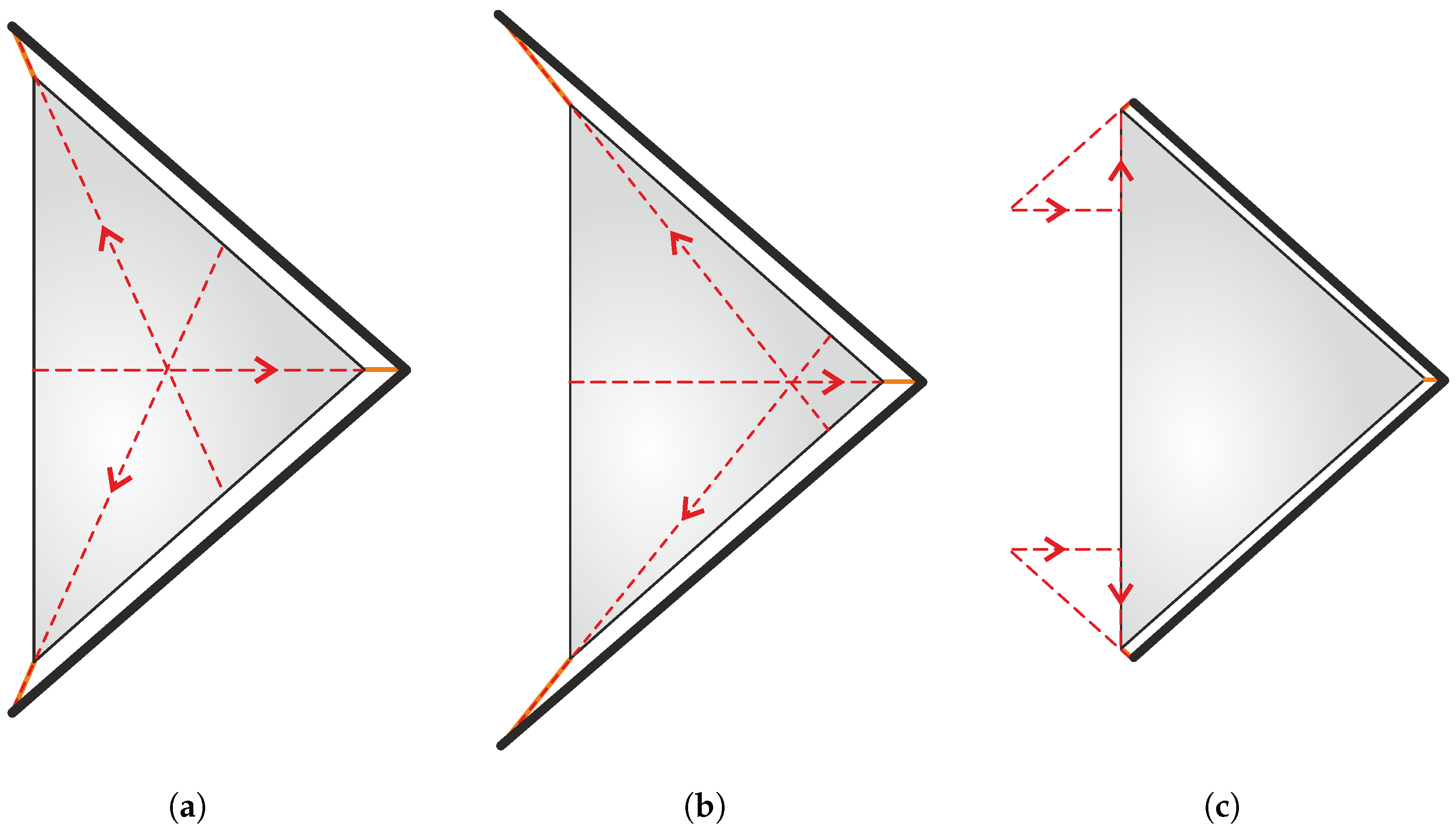
2.3. Pre-Tensioning Application

In principle, a membrane intrinsically has no ability to withstand loads transverse to its mid-plane, being completely devoid of bending stiffness. The technique chosen to give the membrane sufficient rigidity to withstand operational loads is to pre-tension it in advance. A state of pre-tensioning can be induced in a membrane by pulling it at the ends, and that effect then can be achieved in two different ways: (i) by assigning an initial tensile to the connecting cables; or (ii) by assigning an initial compressive load to the booms. These two approaches lead to different technological solutions, which will not be investigated in detail in this work, but classifiable as remote connection via cables or close joining via shorter and stiffer elements.
In the following, we will refer to the connections—via cables or cable-free—to indicate the two configurations described above. The first solution has been described in detail in Refs. [31,32], while the second one is adopted in Ref. [33]. The compression in the boom arms can be introduced directly when they are deployed, while an ad hoc mechanism is necessary to tension the cables. In this work, the performance of the various approaches to pre-tensioning are studied and compared. In particular, the comparison is performed by looking for the minimum intensity of pre-loading to ensure the same maximum out-of-plane deflection of the sail. The ineffectiveness of the induced pre-stress field is demonstrated by the lack of any convergence of the analysis when the SRP-induced effect is applied.
For the four-sector sail, the sensitivity of the external cables to the length is also investigated to highlight the dependence of the stress field induced in the membrane from the direction of the pre-load action line. In particular, three cases are considered: cables of intermediate length, to make their direction coincident with the bisector of the triangular membrane, and cables very long or short; see Figure 5. The pre-tensioning forces, for the three configurations, cross the central part of the membrane sector, the region close to the boom center, and the external edge, respectively.
The analyses performed on the monolithic sail stiffened by cruciform boom highlight some critical aspects of the connection via cables. The lack of co-planarity between the membrane–cable assembly and booms; this is, on the contrary, guaranteed in the sector sail, and can prevent a correct introduction of pre-tensioning. In this case, the transverse component of the force transmitted by sloped cables (see for instance the conceptual scheme in Figure 6a) can induce an out-of-plane deformation of the membrane, which in turn can cause the relaxation of the supporting cables themselves.
In three-dimensional modeling, at least the parallelism between the booms and the membrane–cables assembly would be easily recoverable, creating a connection of the latter with the generic boom external surface instead with its axis; see the scheme in Figure 6b. In the context of a one-dimensional representation of both boom and cables, as in the present analyses, this approach is not viable and an alternative modeling technique is necessary. For this purpose, a special contact constraint is adopted between membrane and cables that forces their parallelism, by imposing an initial clearance between them. In that case, the nodal transmission of forces is preserved as described by the conceptual scheme of Figure 6c.

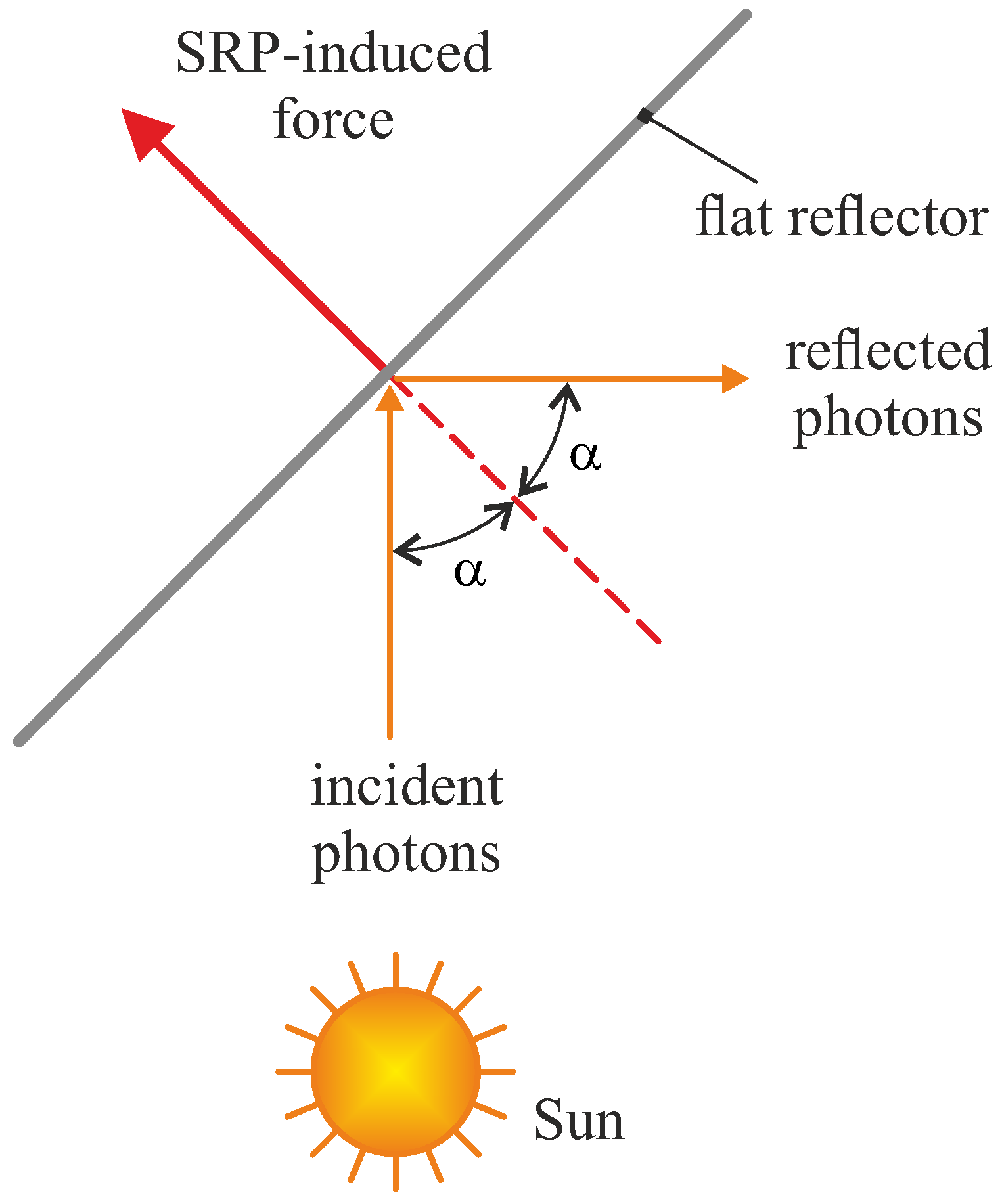
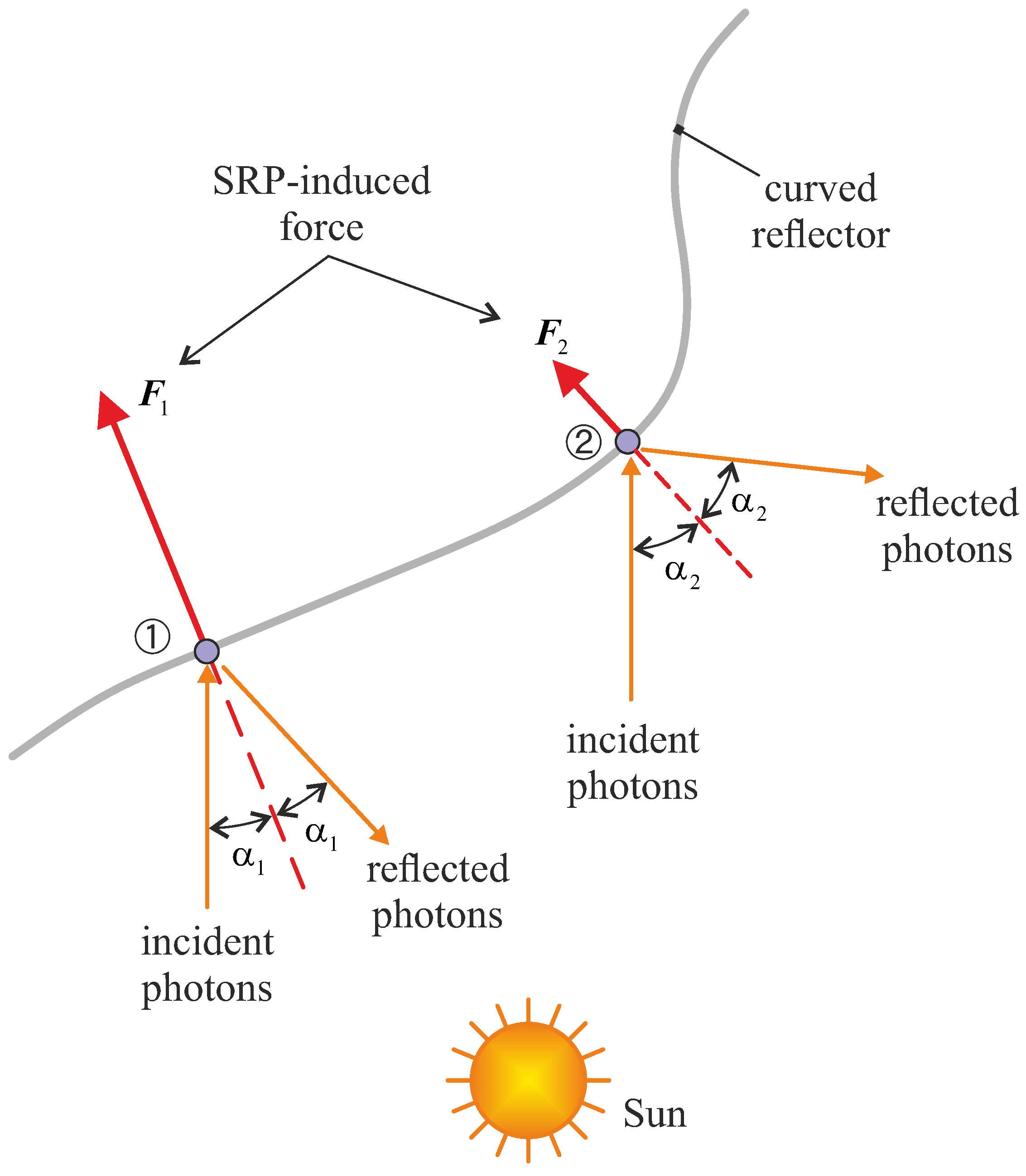
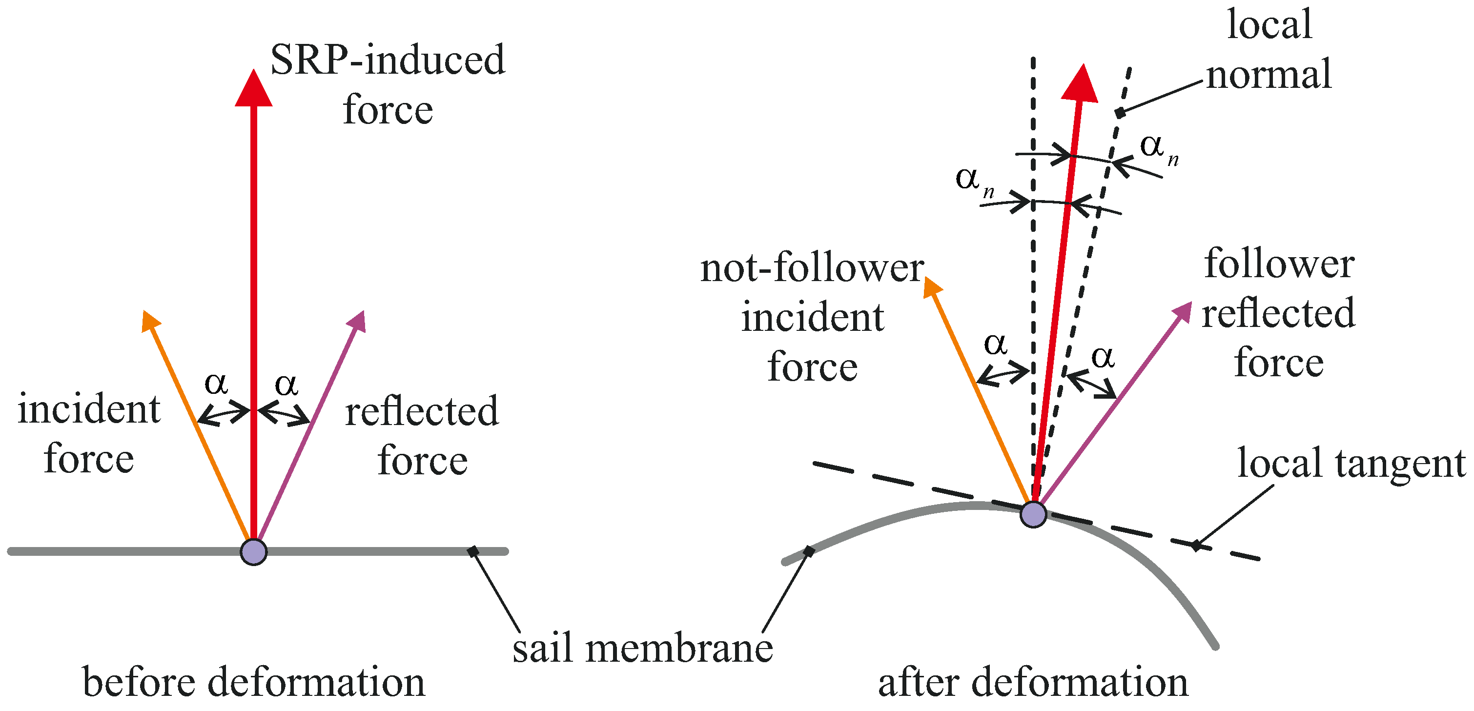
2.4. Solar Radiation Pressure Application

The SRP is the mechanical force per unit area due to the transfer of each photon’s momentum to the opaque surface plus the momentum due to a recoil photon for a (partially) reflective surface. Unlike the case of an absorbing material, the resulting force on a perfectly reflective plate is normal to the exposed surface, with the tangential forces from the incident and reflected solar rays canceling each other; see the scheme in Figure 7.
If the surface of the body is perfectly flat, then the direction of the SRP-induced force coincides with the normal to the surface itself. However, if a surface is curved, then each point will be subject to a force directed as the local normal direction, as sketched in Figure 8. As shown in that figure, not only the direction but also the intensity of the SRP-induced force depends on the local angle α l between the incident sun ray and the normal direction, according to a proportionality factor cos 2 α l [18]. In particular, despite the original flat geometry of the sail, the out-of-plane deflection induced on the membrane surface by the SRP influences interactively the structural response of the spacecraft.
In this context, two methods of increasing accuracy (but also of increasing computational cost) can be used to model the action of the SRP on a deformable surface. The first one is based on assigning the incident and reflected forces separately. For example, assuming a Sun–spacecraft distance equal to one astronomical unit, the magnitude of both (surface) forces is about 4.5 µPa multiplied by the cosine of the angle α between the Sun–spacecraft direction and the normal to the sail surface in the direction opposite to the Sun and in an undeformed configuration.
Within a geometrically non-linear analysis, this method is based on the possibility of applying a surface traction load to rotate with the surface itself (“live load”), so to maintain its inclination with the local normal, or to remain fixed, disregarding the loss of the original incidence (“dead load”). If both the incident and reflected loads were “dead”, then the resultant would be aligned with the normal in undeformed configuration and, in modulus, it would be proportional to the cos 2 α instead of cos 2 α l . If both loads were “live”, then the resultant would be correctly aligned with the normal, but the modulus would remain proportional to the cos 2 α . Finally, if the incident load is “dead” and the reflected one is “live”, then the resultant force is offset by α n with respect to the normal direction, as shown in Figure 9; in the modulus, it is proportional to the cos 2 α l , with α l given by the sum of α and α n . The last solution is here adopted, due to the best compromise between direction and modulus of the predicted resultant force. Such an error can be neglected anyway when the deformations involved are sufficiently small, that is for small-sized sails. Rather, the real limit is represented by having to assign a fixed value to the nominal incidence, excluding the use of such a method to perform dynamic analyses, when the spacecraft attitude can vary continuously.
The second and more refined approach is based on developing a specific subroutine in Fortran language that, by communicating with the processor, at all simulation times and at all points on the sail surface, recalculates direction and intensity of the SRP-induced force, based on the real local angle of incidence. Indeed, the Abaqus user subroutines allow us to customize the program for specific applications that are not available through the main software features. The user subroutines are mostly written in Fortran and, when inserted in a simulation model, the Abaqus processor launches the Fortran compiler automatically. The subroutine here used, named UTRACLOAD, can be used to define the variation of a distributed traction load magnitude as a function of position, time, element number, and load integration point number. In the specific case, the cosine directors of the local normal to the surface are passed as input data to the subroutine, which calculates the actual load magnitude by multiplying the value of solar pressure at zero incidence by the square of the scalar product of this normal with the sun rays’ unit vector. Obviously—especially in the case of large solar sails and very complex dynamic simulations—the use of the subroutine can make the calculation times significantly higher.
In conclusion, the first method, hereinafter indicated as Method 1, despite being approximate, produces more than satisfactory results for static analyses on small–medium-sized sails, without having to resort to resources that are external to the FEM software. On the contrary, the second approach, named Method 2, is free of approximations and has no limitations of use but requires the availability of an external software—in this case, a Fortran compiler that is compliant with the Abaqus suite.

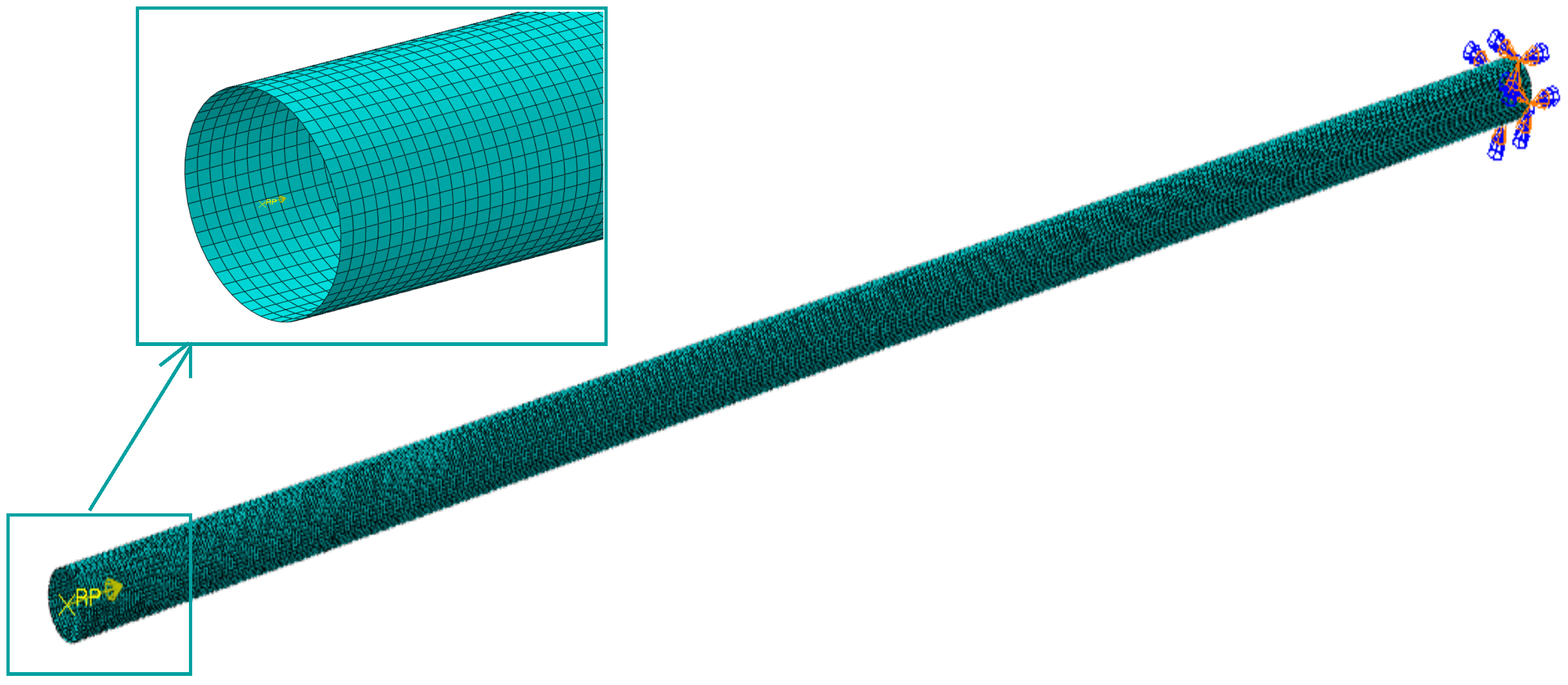
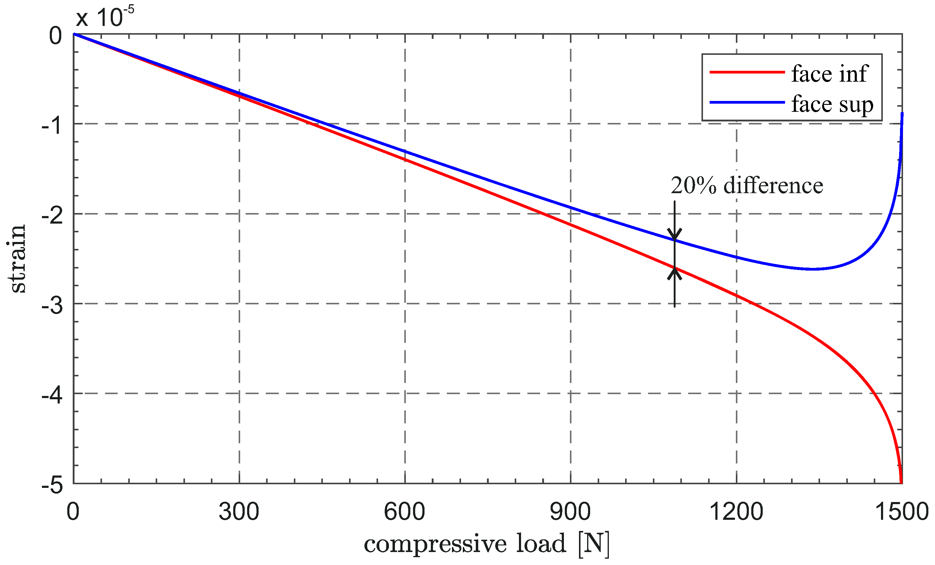
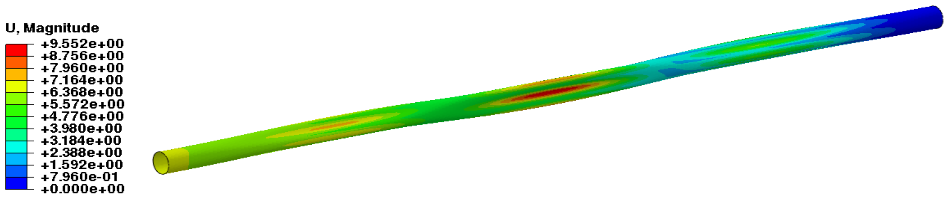
2.5. Boom Buckling Problem

The booms, which play a fundamental role in both the deployment and pre-tensioning phases of the sail, must be sufficiently stiff and at the same time as light as possible. For an assigned material and length of the generic boom, its weight depends on the cross-sectional area, whose dimensions should be minimized as much as possible. In this context, a CFRP boom with thin-walled section represents the best structural solution. The bending stiffness can be increased by distributing the area away from the axis of rotation, while the torsion stiffness is maximum for closed sections. Despite the fact that open sections have also been considered for (relatively) small-sized sails [34], the use of closed sections is recommended for medium-sized sails, as discussed in Ref. [35]. Between the closed section shapes, the most studied one is the bistable Collapsible Tubular Mast (CTM) made of two omega-shaped shells, which provides high stiffness and guarantees easy deployment. In this work, a simply tubular closed section is analyzed, with focus on the stiffness requirements rather than on the deployment process.

3. Numerical Simulation Results
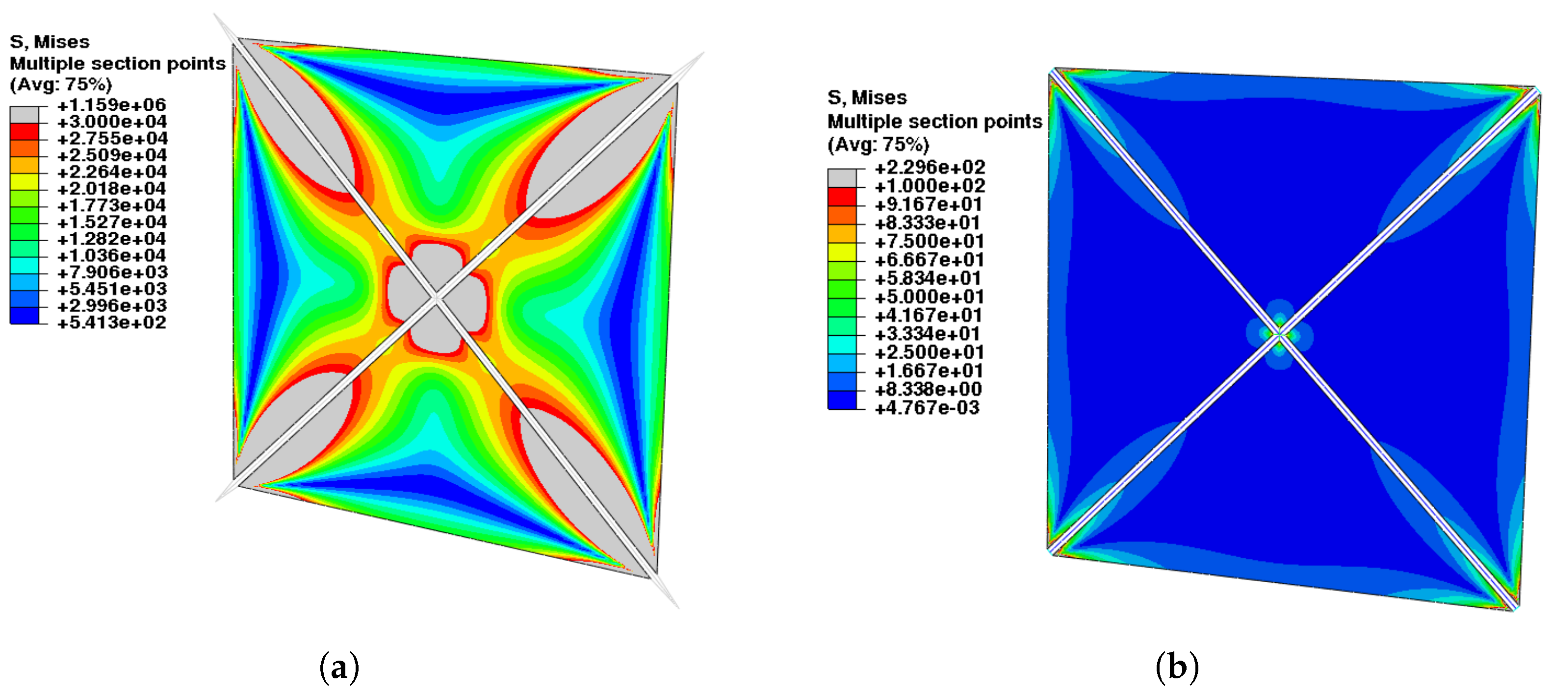
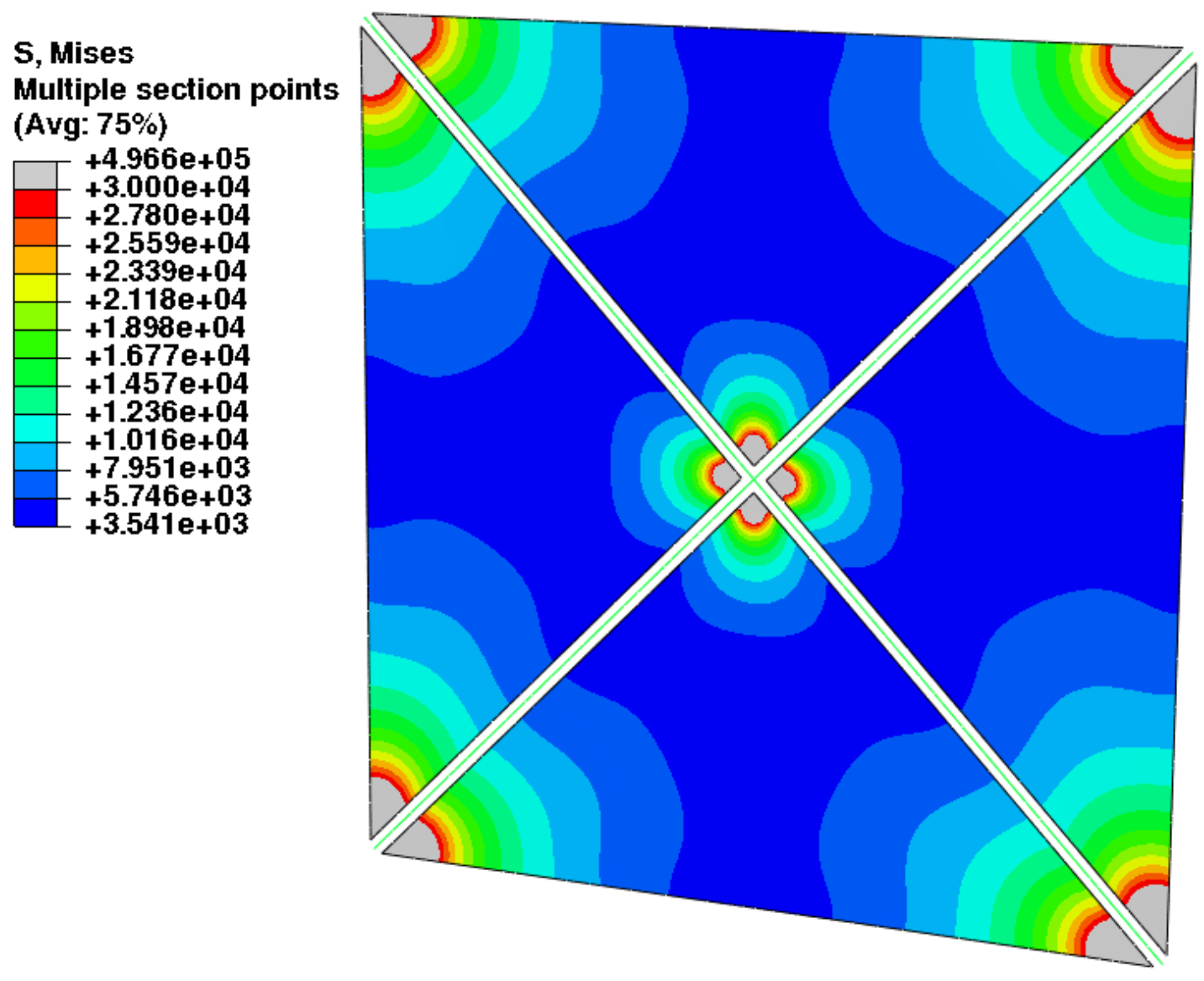
This section presents the numerical simulation results in terms of the stress field induced by tensile pre-tensioning, the out-of-plane displacement field induced by SRP, and the boom buckling modes. Both the monolithic and the four-triangular sector configurations are analyzed.

3.1. Pre-Tensioning

The pre-tensioning induced in the sector sail by assigning a tensile stress of 23.5   MPa to the cables is shown in Figure 10. The reason why this value is applied to the cables is to achieve the reference stress of about 7 kPa in the central area of the membrane, as suggested in Ref. [31]. Furthermore, all the remaining techniques of pre-tensioning are driven by this reference value, which is a good compromise between the increment of the membrane bending stiffness and the absence of deep wrinkles. From the figure, it is also evident that the stress does not fall below the value of 5   kPa at any point. The length of the external cables is such that their direction coincides with the bisector of the triangular region—see Figure 5—so a quite-uniform action of the pre-tensioning force is obtained.
In Figure 11, the two extreme cases of very long cables and short cables are reported. In both configurations, the pre-stress field induced in the sail is ineffective in balancing the SRP, causing the simulation to diverge early. In particular, when the cables are too short, the membrane portion close to the boom center is substantially unloaded; meanwhile, the excessively long cables cannot induce sufficient stress, below 550   Pa , in a triangular region close to the external edges. Neither of the results change qualitatively by increasing the tensile stress of the cables up to 30   MPa .
The same result is obtained in the cable-free configuration by applying an initial compression to the boom of 2.15   MN ; see Figure 12.
The impossibility of pre-tensioning a monolithic sail with oblique cables (see Figure 6a) is visible in Figure 13; here, the membrane, despite an initial stress of 50   MPa in each cable, remains substantially unloaded. A satisfactory result is instead obtained when the alignment between cables and membrane is restored. According to the scheme in Figure 6c, an initial tensile stress of 19.5   MPa in the four cables produces the pre-tensioning shown in Figure 13.
A very similar stress field can be induced in the monolithic sail by means of cable-free pre-tensioning by applying an initial compression of 0.95   MPa to the arms of the cruciform boom, or by imposing to the cables connected to the frame boom an initial tension of 35   MPa . In this last case, the membrane, cables, and boom lie on the same plane, but a larger pre-loading, still strongly below the resistance of Kevlar, is necessary: a large part of the cable force acts as shear at frame boom ends and causes a part of elastic deformation energy to be spent in boom shear bending deformation rather than in sail tensioning.

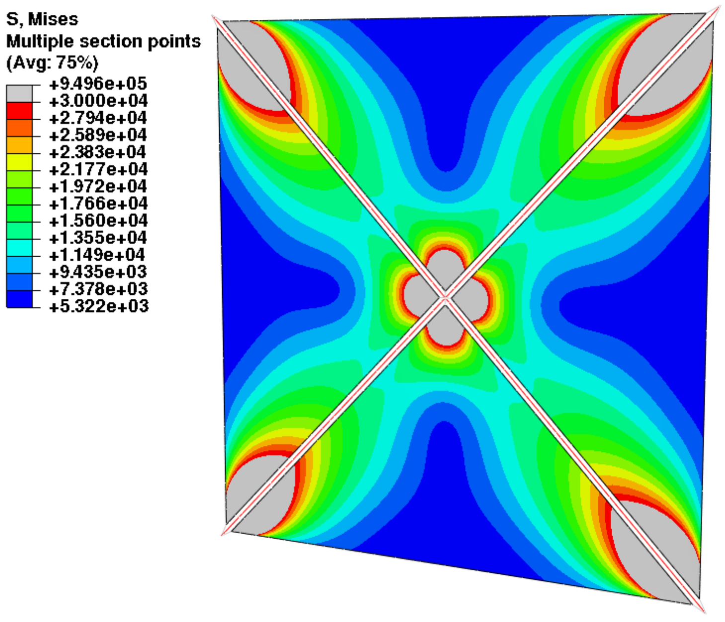
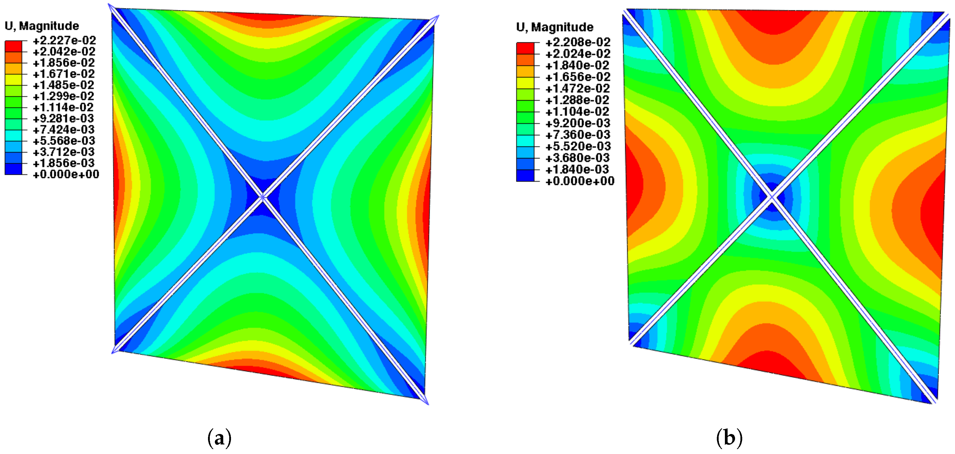
3.2. Solar Radiation Pressure
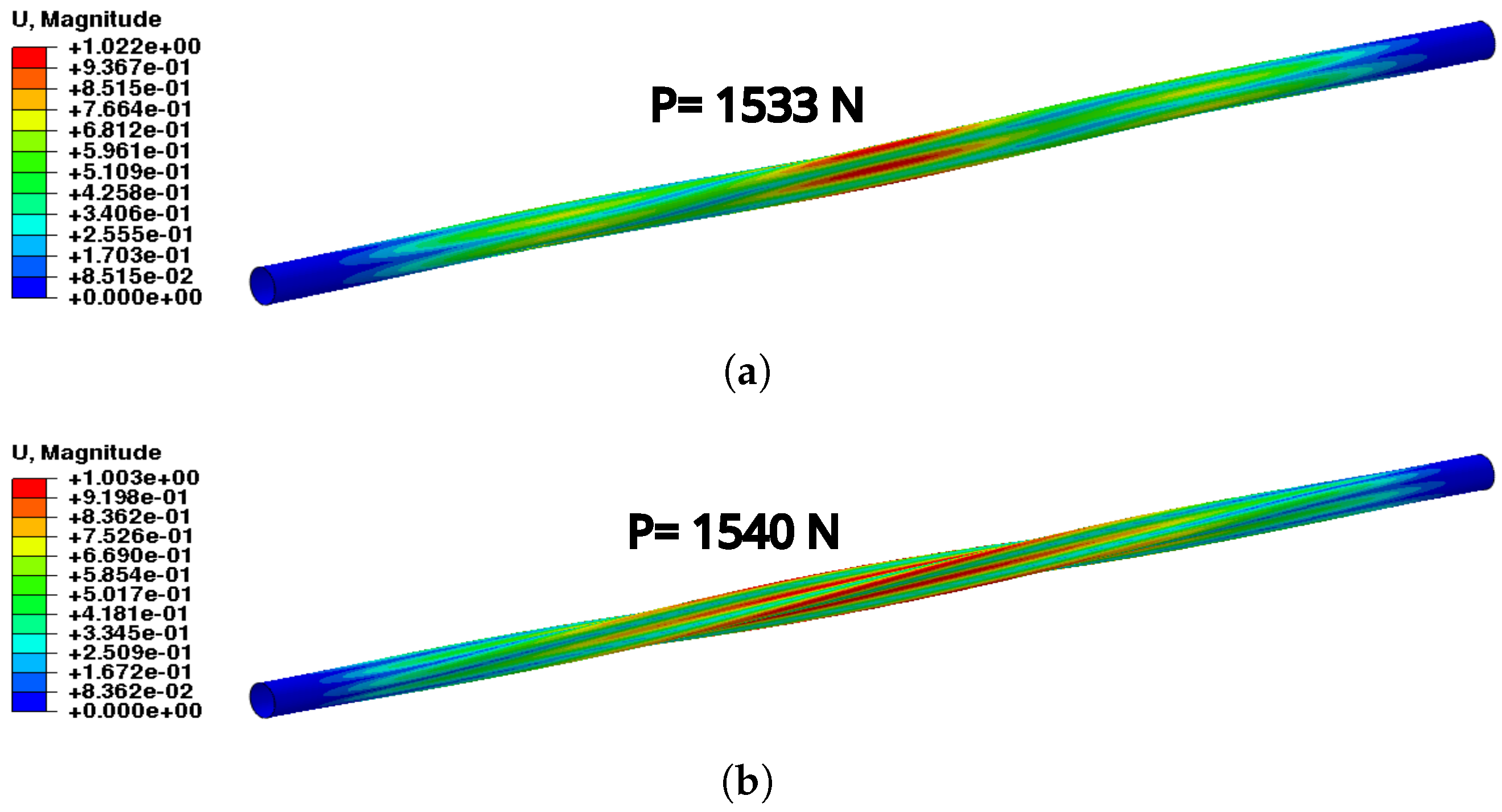
In the present work, which deals with the static analysis of a medium-sized spacecraft, the results provided by the two approaches to apply the SRP (see the discussion in Section 2.4) are very similar and the simulation time does not exhibit appreciable variations. The maximum deflection of the membrane is averagely overestimated by Method 1 by only 0.1 % , because of the slightly underestimated local angle of incidence. In the following, only the out-of-plane displacement field relevant to Method 2 are shown.
As discussed in Section 2.3, all the sail configurations are pre-stressed in such a way to cause approximately the same value of maximum deflection, fixed at about 22   mm . The displacement induced by the SRP at the reference distance of one astronomical unit from the Sun and a nominal incidence of zero degrees in the four-sector sail is shown in Figure 14. Note that the chosen value for SRP is consistent with heliocentric scenarios in the proximity of Earth’s orbit, such as transfers to near-Earth objects, the maintenance of displaced non-Keplerian orbits for the observation of Earth’s poles, or the initial stages of interplanetary transfers towards other planets. The maximum deflection relevant to the two pre-tensioning techniques, based on pre-stressing cables in traction or boom arms in compression, is 22.1   mm on average and occurs at mid-points of the external edges. However, the whole displacement field exhibits some differences: the regions where the deflection is higher, above 15   mm , are definitively larger in the cable-free case. This behavior is to be attributed to the different contribution of the pre-tensioning forces at the internal vertices of the membrane sectors, close to the center of the sail: here, the deformations of the boom—the primary source of pre-tension in the cable-free configuration—tend to cancel out for symmetry reasons; this phenomenon is not present in pre-tensioning with cables, where the internal ones are also actively pre-loaded.
The results relevant to the same loading conditions are shown in Figure 15 for the monolithic sail. The maximum deflection, 22.15   mm on average, occurs in the center of the membrane, consistently with the adopted four-point connection. The case of cable-free configuration is not shown, due to the total coincidence of the results with those of the cross boom via the cable: the absence of inner connections, differently from the four-sector sail, makes the two cases identical. Finally, also the displacement field relevant to the frame boom is fully comparable with the previous ones, with the pre-tensioning technique being the same: the less effective loading of the frame boom is compensated for by increasing the cable pretension force, as explained in Section 2.3.

3.3. Boom Buckling

The results that are relevant to the linear buckling analysis are shown in Figure 16. The first four eigenvalues are equal two by two, and they all exhibit eigenvectors with simultaneous global torsion and local section distortion. In Figure 16, only the first and third eigenvectors are reported; these are relevant to the loads of 1533   N and 1540   N , respectively, since the second and fourth differ only in the torsion direction. As explained in Ref. [36], the buckling behavior of the thin-walled cylinder in the composite material is affected by several factors: section shape and size, thickness, global length, composite lay-up, and finally sensitivity to initial imperfections.
The last factor, as well as the extreme slenderness of the boom, require a non-linear analysis to be performed. The initial perturbation on the boom geometry is introduced as the sum of the same percentage of the two eigenvectors mentioned above, to obtain a defect amplitude of a hundredth, a tenth, and a millimeter, respectively. The criterion to calculate the critical load is based on the ascertainment of loss of constant compressive strain in the thickness when buckles arise. The occurrence of buckling is conventionally fixed at 20 % of strain divergence between internal and external faces at a reference critical location. Figure 17 shows the application of such a criterion for the intermediate value of geometrical perturbation. The deformation induced by non-linear buckling, which is shown in Figure 18, is qualitatively consistent with the predicted eigenvectors and occurs at about 95 % , 74 % , and 43 % of the linear critical load, for increasing perturbation amplitude. The stress value of 3.2   MPa , relevant to the larger initial perturbation, is however lower than 1   MPa , evaluated as the maximum boom compressive stress in all sail simulations.

4. Conclusions

Through the FE analyses, the Abaqus software was demonstrated to be an effective instrument for modeling classical square solar sails and for deeply understanding the performance and criticality of possible structural solutions. In particular, the developed numerical approaches and modeling techniques can provide precious information about many design aspects: membrane pre-tensioning, deformation induced by the SRP, and the boom buckling problem. Special attention is devoted to reproducing realistic loading and boundary conditions in the space, trying to supplement the lack of experimental data.
The same procedure can be extended to square solar sail of different size and arranged with various combination of technical solutions. Furthermore, thanks to the Fortran subroutine developed to impose the SRP, the dynamic response of the sail can also be analyzed by replacing an implicit non-linear static step with a dynamic one. In conclusion, the FE method—integrated using skills that are specific to the Abaqus software—can be considered a powerful and versatile approach for progressing with the study of promising spacecrafts, such as solar sails.

Author Contributions

Conceptualization, L.B. and A.A.Q.; methodology, L.B.; software, L.B.; writing—original draft preparation, L.B.; writing—review and editing, L.B., M.B. and A.A.Q. All authors have read and agreed to the published version of the manuscript.

Funding

This research received no external funding.

Data Availability Statement

Data are contained within the article.

Conflicts of Interest

The authors declare no conflicts of interest.

References

  1. Gong, S.; Macdonald, M. Review on solar sail technology. Astrodynamics 2019, 3, 93–125. [Google Scholar] [CrossRef]
  2. Fu, B.; Sperber, E.; Eke, F. Solar sail technology—A state of the art review. Prog. Aerosp. Sci. 2016, 86, 1–19. [Google Scholar] [CrossRef]
  3. Johnson, L.; Young, R.; Barnes, N.; Friedman, L.; Lappas, V.; McInnes, C.R. Solar Sails: Technology Furthermore, Demonstration Status. Int. J. Aeronaut. Space Sci. 2012, 13, 421–427. [Google Scholar] [CrossRef]
  4. Zhao, P.; Wu, C.; Li, Y. Design and application of solar sailing: A review on key technologies. Chin. J. Aeronaut. 2023, 36, 125–144. [Google Scholar] [CrossRef]
  5. Mori, O.; Shirasawa, Y.; Mimasu, Y.; Tsuda, Y.; Sawada, H.; Saiki, T.; Yamamoto, T.; Yonekura, K.; Hoshino, H.; Kawaguchi, J.; et al. Overview of IKAROS Mission. In Advances in Solar Sailing; Macdonald, M., Ed.; Springer: Berlin/Heidelberg, Germany, 2014; Chapter 3; pp. 25–43. [Google Scholar] [CrossRef]
  6. Umesato, M.; Okahashi, T. Development of small solar power sail demonstrator IKAROS. NEC Tech. J. 2011, 6, 52–56. [Google Scholar]
  7. Tanaka, Y.; Shibuya, K.; Negishi, M.; Fujino, H.; Mori, T. The great challenge of “IKAROS”: A space yacht flying with a solar sail. J. Inst. Electr. Eng. Jpn. 2011, 131, 336–340. [Google Scholar] [CrossRef]
  8. Tsuda, Y.; Mori, O.; Funase, R.; Sawada, H.; Yamamoto, T.; Saiki, T.; Endo, T.; Kawaguchi, J. Flight status of IKAROS deep space solar sail demonstrator. Acta Astronaut. 2011, 69, 833–840. [Google Scholar] [CrossRef]
  9. Matsushita, M.; Okuizumi, N.; Mori, O.; Satou, Y.; Iwasa, T.; Matunaga, S. Influence of curved thin-film device on deformation of a solar sail. Adv. Space Res. 2021, 67, 2628–2642. [Google Scholar] [CrossRef]
  10. Okuizumi, N.; Satou, Y.; Mori, O.; Sakamoto, H.; Furuya, H. Analytical investigation of global deployed shape of a spinning solar sail membrane. AIAA J. 2021, 59, 1075–1086. [Google Scholar] [CrossRef]
  11. Boden, R.C.; Hernando-Ayuso, J. Shape estimation of gossamer structures using distributed sun-angle measurements. J. Spacecr. Rocket. 2018, 55, 415–426. [Google Scholar] [CrossRef]
  12. Zhang, F.; Gong, S.; Baoyin, H. Three-Axes Attitude Control of Solar Sail Based on Shape Variation of Booms. Aerospace 2021, 8, 198. [Google Scholar] [CrossRef]
  13. Matsushita, M.; Okuizumi, N.; Satou, Y.; Mori, O.; Iwasa, T.; Matunaga, S. Influence of thin-film device with curvature on natural frequency of rectangle membrane under uniaxial tension. Astrodynamics 2019, 3, 257–272. [Google Scholar] [CrossRef]
  14. Sproewitz, T.; Grundmann, J.T.; Seefeldt, P.; Spietz, P.; Hillebrandt, M.; Jahnke, R.; Mikulz, E.; Renger, T.; Reershemius, S.; Sasaki, K.; et al. Membrane Deployment Technology Development at DLR for Solar Sails and Large-Scale Photovoltaics. In Proceedings of the IEEE Aerospace Conference, Big Sky, MT, USA, 2–9 March 2019. [Google Scholar] [CrossRef]
  15. Zhang, F.; Gong, S.; Gong, H.; Baoyin, H. Solar sail attitude control using shape variation of booms. Chin. J. Aeronaut. 2022, 35, 326–336. [Google Scholar] [CrossRef]
  16. Chen, T.Z.; Liu, X.; Cai, G.P.; You, C.L. Attitude and vibration control of a solar sail. Adv. Space Res. 2023, 71, 4557–4567. [Google Scholar] [CrossRef]
  17. Boni, L.; Bassetto, M.; Niccolai, L.; Mengali, G.; Quarta, A.A.; Circi, C.; Pellegrini, R.C.; Cavallini, E. Structural response of Helianthus solar sail during attitude maneuvers. Aerosp. Sci. Technol. 2023, 133, 1–9. [Google Scholar] [CrossRef]
  18. McInnes, C.R. Solar Sailing: Technology, Dynamics and Mission Applications; Springer-Praxis Series in Space Science and Technology; Springer: Berlin/Heidelberg, Germany, 1999; Chapter 2; pp. 38–40. [Google Scholar] [CrossRef]
  19. Boni, L.; Mengali, G.; Quarta, A.A. Finite Element Analysis of Solar Sail Force Model with Mission Application. Proc. Inst. Mech. Eng. Part G: J. Aerosp. Eng. 2019, 233, 1838–1846. [Google Scholar] [CrossRef]
  20. Seefeldt, P.; Grundmann, J.T.; Hillebrandt, M.; Zander, M. Performance analysis and mission applications of a new solar sail concept based on crossed booms with tip-deployed membranes. Adv. Space Res. 2021, 67, 2736–2745. [Google Scholar] [CrossRef]
  21. Bassetto, M.; Niccolai, L.; Boni, L.; Mengali, G.; Quarta, A.A.; Circi, C.; Pizzurro, S.; Pizzarelli, M.; Pellegrini, R.C.; Cavallini, E. Sliding mode control for attitude maneuvers of Helianthus solar sail. Acta Astronaut. 2022, 198, 100–110. [Google Scholar] [CrossRef]
  22. Landini, F.; Frassetto, F.; Zangrilli, L.; Caracci, V.; Riva, A.; Loreggia, D.; Redaelli, E.; Riva, M.; Pellegrini, R.; Cavallini, E.; et al. SailCor: Compact coronagraph for the Helianthus sub-L1 Mission with solar photonic propulsion. In Proceedings of the International Conference on Space Optics—ICSO 2022, Dubrovnik, Croatia, 3–7 October 2023; Minoglou, K., Karafolas, N., Cugny, B., Eds.; SPIE: Bellingham, WA, USA, 2022. [Google Scholar] [CrossRef]
  23. Aliasi, G.; Mengali, G.; Quarta, A.A. Artificial Lagrange points for solar sail with electrochromic material panels. J. Guid. Control. Dyn. 2013, 36, 1544–1550. [Google Scholar] [CrossRef]
  24. Mu, J.; Gong, S.; Ma, P.; Li, J. Dynamics and control of flexible spinning solar sails under reflectivity modulation. Adv. Space Res. 2015, 56, 1737–1751. [Google Scholar] [CrossRef]
  25. Anonymous. Abaqus Scripting User’s Guide; Dassault Systèmes: Paris, France, 2022. [Google Scholar]
  26. Anonymous. Abaqus User Subroutines Reference Guide; Dassault Systèmes: Paris, France, 2022. [Google Scholar]
  27. Anonymous. Abaqus Theory Manual; Dassault Systèmes: Paris, France, 2022. [Google Scholar]
  28. Satou, Y.; Okuizumi, N.; Sakamoto, H.; Furuya, H.; Ono, G.; Shirasawa, Y.; Mori, O. Nonflatness of Solar Sail Membrane Predicted by Nonlinear Finite Element Analyses. In Proceedings of the Spacecraft Structures Conference, National Harbor, MA, USA, 13–17 January 2014. [Google Scholar] [CrossRef]
  29. Satou, Y.; Mori, O.; Okuizumi, N.; Shirasawa, Y.; Furuya, H.; Sakamoto, H. Deformation Properties of Solar Sail IKAROS Membrane with Nonlinear Finite Element Analyses. In Proceedings of the 2nd AIAA Spacecraft Structures Conference, Kissimmee, FL, USA, 5–9 January 2015. Paper AIAA 2015-0436. [Google Scholar] [CrossRef]
  30. Wright, J.L. Space Sailing; Gordon and Breach Science: Langhorne, PA, USA, 1992; pp. 223–226. [Google Scholar]
  31. Sleight, D.; Muheim, D. Parametric studies of square solar sails using finite element analysis. In Proceedings of the 45th AIAA/ASME/ASCE/AHS/ASC Structures, Structural Dynamics & Materials Conference, Palm Springs, CA, USA, 19–22 April 2004. [Google Scholar] [CrossRef]
  32. Boni, L.; Mengali, G.; Quarta, A.A. Solar sail structural analysis via improved finite element modeling. Proc. Inst. Mech. Eng. Part G: J. Aerosp. Eng. 2017, 231, 306–318. [Google Scholar] [CrossRef]
  33. Biddy, C.; Svitek, T. LightSail-1 solar sail design and qualification. In Proceedings of the 41st Aerospace Mechanisms Symposium, Pasadena, CA, USA, 16–18 May 2012. [Google Scholar]
  34. Banik, J.; Murphey, T. Performance validation of the triangular rollable and collapsible mast. In Proceedings of the 24th Annual AIAA/USU Conference on Small Satellites, Logan, UT, USA, 9–12 August 2010. [Google Scholar]
  35. Sickinger, C.; Herbeck, L.; Breitbach, E. Structural engineering on deployable CFRP booms for a solar propelled sailcraft. Acta Astronaut. 2006, 58, 185–196. [Google Scholar] [CrossRef]
  36. Almeida, J.H.S.; Bittrich, L.; Jansen, E.; Tita, V.; Spickenheuer, A. Buckling optimization of composite cylinders for axial compression: A design methodology considering a variable-axial fiber layout. Compos. Struct. 2019, 222, 110928. [Google Scholar] [CrossRef]
Figure 1. Conceptual scheme of a four sector solar sail in five points connection configurations. (a) Cross boom with cables. (b) Cable-free cross boom.
Aerospace 11 00151 g001
Figure 2. Conceptual scheme of a monolithic solar sail in four points connection configurations. (a) Cross boom with cables (rear view). (b) Cable-free cross boom. (c) Frame boom with cables.
Aerospace 11 00151 g002
Figure 3. Example of mesh and constraints used in the numerical simulations. (a) Sector sail. (b) Monolithic sail.
Aerospace 11 00151 g003
Figure 4. Single arm of the cruciform boom: mesh and loading conditions.
Aerospace 11 00151 g004
Figure 5. Conceptual diagram of cables of different lengths. (a) Bisector cables. (b) Long cables. (c) Short cables.
Aerospace 11 00151 g005
Figure 6. Conceptual scheme of the membrane–cables–boom reciprocal positioning. Cases: (a) cables sloped; (b) cables aligned; (c) FEM solution for cable alignment.
Aerospace 11 00151 g006
Figure 7. Diagram of the force induced by the SRP on an ideal flat reflector.
Aerospace 11 00151 g007
Figure 8. Solar-radiation-induced force on a curved reflector, in which α l = { α 1 , α 2 } is the local value of the angle of incidence in two generic (different) points { , } along the exposed surface.
Aerospace 11 00151 g008
Figure 9. Approximate method to apply SRP accounting for the solar sail deformation.
Aerospace 11 00151 g009
Figure 10. Four-sector sail: stress field induced by tensile pre-tensioning of cables with intermediate length.
Aerospace 11 00151 g010
Figure 11. Four-sector sail: stress field induced by tensile pre-tensioning of very long and short cables. (a) Very long cables. (b) Very short cables.
Aerospace 11 00151 g011
Figure 12. Four-sector sail: stress field induced by compressive pre-tensioning of boom arms in cable-free configuration.
Aerospace 11 00151 g012
Figure 13. Monolithic sail: stress field induced by tensile pre-tensioning of cables in sloped and aligned position. (a) Sloped cables. (b) Aligned cables.
Aerospace 11 00151 g013
Figure 14. Four-sector sail: out-of-plane displacement field induced by SRP. (a) Via cables. (b) Cable-free.
Aerospace 11 00151 g014
Figure 15. Monolithic sail: out-of-plane displacement field induced by SRP. (a) Cross boom via cables. (b) Frame boom via cables.
Aerospace 11 00151 g015
Figure 16. Buckling modes. (a) First mode. (b) Second mode.
Aerospace 11 00151 g016
Figure 17. Strain divergence for buckling detection.
Aerospace 11 00151 g017
Figure 18. Non-linear boom buckling deformation.
Aerospace 11 00151 g018
Table 1. Material properties used in the numerical simulations.
ComponentsMaterialModulus (GPa)Poisson’s RatioDensity (kg/m3)
SailAluminized Kapton 2.48 0.34 1572
BoomComposite124 0.3 1600
CableKevlar62 0.36 1440
Table 2. Composite properties used in the numerical simulations.
E 11 (GPa) E 22 (GPa) E 33 (GPa) ν 12 { ν 13 , ν 23 } { G 12 , G 13 } (GPa) G 23 (GPa)
1245122 0.8 0.2 57 8.5
Disclaimer/Publisher’s Note: The statements, opinions and data contained in all publications are solely those of the individual author(s) and contributor(s) and not of MDPI and/or the editor(s). MDPI and/or the editor(s) disclaim responsibility for any injury to people or property resulting from any ideas, methods, instructions or products referred to in the content.

