Article

Sizing of Multicopter Air Taxis—Weight, Endurance, and Range

1
Key Laboratory of Autonomous Systems and Networked Control, Ministry of Education, Guangdong Engineering Technology Research Center of Unmanned Aerial Vehicle Systems, School of Automation Science and Engineering, South China University of Technology, Guangzhou 510640, China
2
Institute of Unmanned System, Beihang University, Beijing 100191, China
3
Department of Naval Architecture and Ocean Engineering, Shanghai Jiao Tong University, Shanghai 200240, China
4
Department of Mechanics and Aerospace Engineering, Southern University of Science and Technology, Shenzhen 518055, China
5
Rotor Aerodynamics Key Laboratory, China Aerodynamic Research and Development Center, Mianyang 621000, China
6
Chair of Artificial Intelligence and Aerodynamics, School of Mechanical Engineering and Automation, Harbin Institute of Technology, Shenzhen 518055, China
7
Guangdong Provincial Key Laboratory of Intelligent Morphing Mechanisms and Adaptive Robotics, Harbin Institute of Technology, Shenzhen 518055, China
*
Authors to whom correspondence should be addressed.
Aerospace 2024, 11(3), 200; https://doi.org/10.3390/aerospace11030200
Submission received: 31 January 2024 / Revised: 24 February 2024 / Accepted: 26 February 2024 / Published: 1 March 2024

Abstract

:
In the near future, urban air mobility (UAM) will let an old dream of human society come true: affordable and fast air transportation for almost everyone. Among the various existing designs, the multicopter configuration best combines the advantages of compactness, simplicity, and maturity. These aspects are important for actual use, particularly during the early stage of this market. This study elaborates on the design principles of UAM multicopters by examining existing models in terms of their configuration, weight, and range specifications. In particular, the weights of the different components are estimated based on empirical models, aerodynamic fundamentals for the analysis of UAM multicopters are derived from momentum theory, and the power and energy requirements for hovering and cruise flight are evaluated, thereby enabling estimation of the maximum hovering time and flight range. Finally, a sizing method is introduced and validated against an actual UAM design.

1. Introduction

1.1. Rising Demand of Electric UAM

UAM is an emerging industry offering a new mode of transportation in a city’s lower altitude airspace. According to the Morgan Stanley report [1] the market of electrical vertical take-off and landing (eVTOL) aircraft is predicted to grow to around 10 trillion USD by 2050, which is much larger than the markets of cars, trucks, trains, and civil aircraft combined. The United Nations forecast that 68% of the world population will live in urban areas, while the global population will increase to 9.8 billion by 2050 [2]. Already congested cities with continuously rising populations will challenge the private and public transportation systems. The volume of merchandise transported, car rides, and the number of passengers of public transport vehicles within the cities are all expected to increase [3]. With the advances in technology brought on by distributed and/or electric propulsion, low-level airspace vehicles may become sufficiently safe, sustainable, and quiet [4], thereby rendering them a viable option to solve future traffic problems.
UAM constitutes a complement to and offers a number of advantages over current modes of transportation, e.g., automobiles and general aviation. First of all, the commute time with UAM vehicles can be reduced with respect to ground transportation, in particular cars. UAM was found to have a potential time-saving effect in the order of tens of minutes when compared to ground transportation modes for congested scenarios encountered in cities, even when considering the required ground transportation time to board the UAM vehicle [5,6]. Secondly, hard-to-reach areas can be accessed by UAM vehicles with ease when compared to ground vehicles, since mountainous terrain, water, buildings, etc., do not pose obstacles. Thirdly, the operating costs of UAM vehicles are lower compared to general aviation. Since electric motors are simpler, mainly due to the smaller number of moving parts, and operated at lower temperatures relative to combustion engines, their maintenance cost is lower [7]. In some territories, electric energy costs as little as 30% of the equivalent energy delivered from aviation fuel [8,9]. Moreover, UAM vehicles can be operated autonomously and thus save costs relative to means of transport depending on a driver or pilot. Also, the environmental impact can be reduced as a result of electric propulsion, directly emitting no greenhouse gases, and the noise footprint of UAM vehicles is smaller when compared to helicopters [10]. Finally, they produce no lead emissions unlike general aviation aircraft with piston engines [7].
Among the various existing electric UAM designs, which include multicopters, lift and cruise, tilt wing, and tilt rotor designs, the multicopter configuration has a successful history of application in the drone industry. This experience is important when it comes to the transportation of passengers during the initial stage of this market. Therefore, this study focuses on UAM multicopters.

1.2. Existing UAM Multicopters

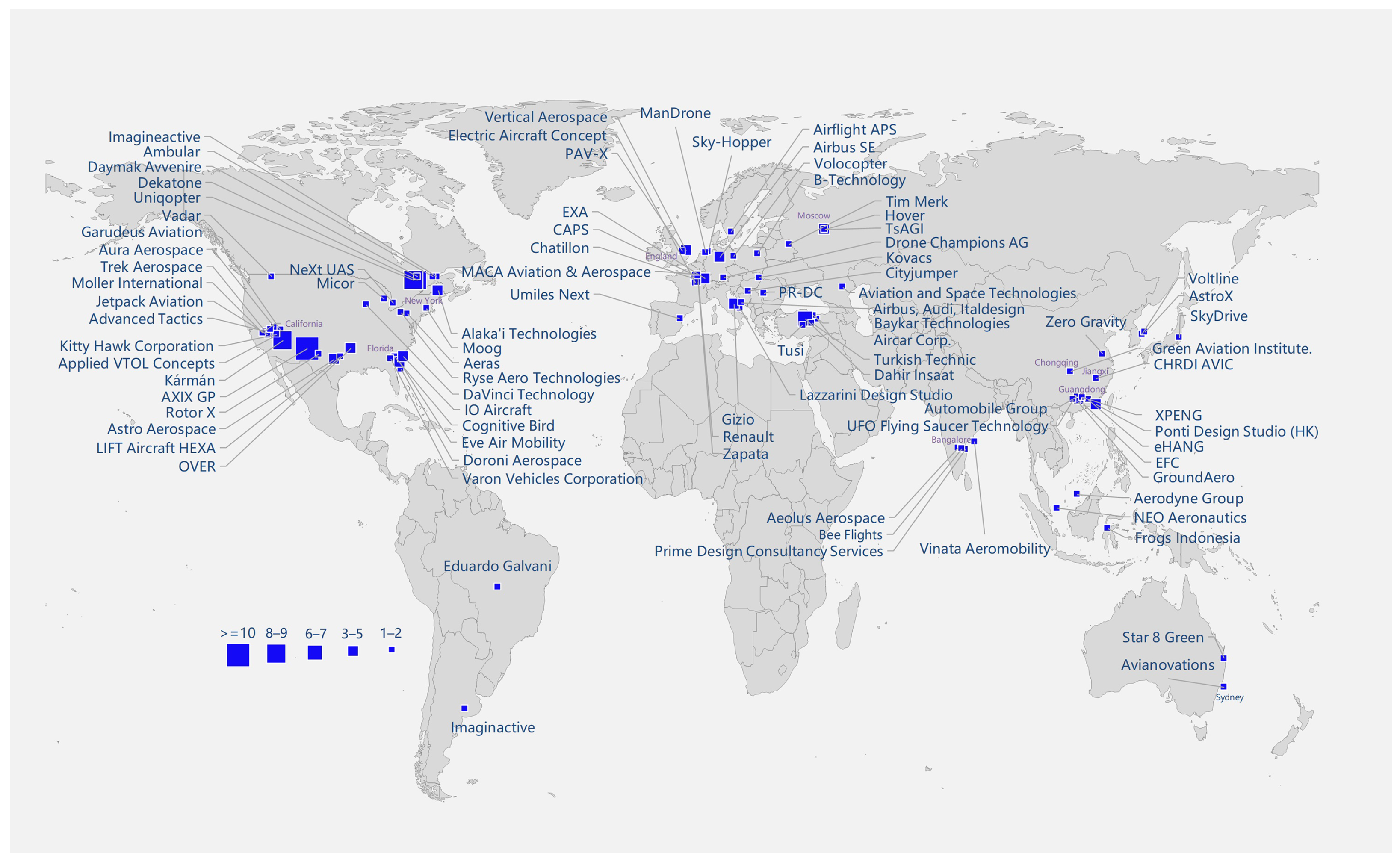
Figure 1 summarizes the geographical origin of almost 250 different multicopter designs for UAM purposes [11]. The size of the symbols represents the number of passengers for different manufacturers. The main configurations for multicopters are based on coplanar and coaxial rotors. Other configurations like ducted fans appear further from application. Some manufacturers reported more than two passengers, but none has yet demonstrated a corresponding flight test yet. In the category of one- and two-passenger UAM vehicles, very few have been subjected to full-scale flight tests, and even fewer have any outlook for successful certification and commercial launch in the foreseeable future [11]. Representative UAM multicopters and the features are depicted in Figure 2.
Currently, battery-powered UAM multicopters are designed for only one or two passengers with real applications. Single-seat multicopters are dominated by coaxial rotors and have a maximum take-off weight (MTOW) ranging from 300 kg to 400 kg as shown in Figure 2a. The MTOW of two-seat multicopters varies significantly between coaxial and coplanar rotors. A UAM multicopter with a coaxial rotor configuration weighs about 600 kg, while the coplanar rotor is significantly heavier at about 900 kg.
One well-known coplanar multicopter model was designed by Volocopter, a company founded in Germany in 2011. They have developed 14 different types of flight vehicles, 10 of which are passenger aircraft. The most recent Volocopter model, VoloCity, is the company’s first production model. Its MTOW is 900 kg, including a maximum payload of 200 kg [12]. VoloCity has 18 fixed-pitched rotors with 18 electric motors mounted on top of a beam structure. The diameter of the rotors is 2.3 m [12]. The VoloCity can fly at a maximum cruising speed of 100 km/h (Figure 2b shows a comparison with other UAM multicopters) for a range of 35 km (a comparison with other UAM multicopters is shown in Figure 2c). It was reported that 5 min is sufficient to exchange the batteries for VoloCity, which drastically reduces turnaround times and allows for almost continuous service time [11]. According to Volocopter, the sound level of the VoloCity perceived by a receiver on the ground is only 65 dB(A) when hovering at an altitude of 75 m [11]. Therefore, it is anticipated to become the quietest certified air taxi, thus blending into the existing noise of a city as advertised by Volocopter [10]. Flight control is achieved by varying the speed of the 18 rotors independently. Since the coplanar configuration has more booms for rotor support when compared to coaxial rotor designs, its structural weight and form drag are expected to be larger.
Other examples of coplanar multicopters include the LIFT Aircraft HEXA, the Gelisim University TUSI, the Star 8 Green EMAV-2, and the Kitty Hawk Flyer. The HEXA features 18 coplanar rotors on top of its cabin with an empty weight of 196 kg, maximum payload og 113 kg, and an endurance of 15 min [11,13]. Gelisim University TUSI is a single-seat eVTOL and ground vehicle, which is colloquially also described as a flying car. The TUSI has six rotors, six electric motors powered by batteries, and fixed tricycle-type wheels used as landing gears and for ground travel [14]. Its empty weight is 100 kg, and its MTOW is 180 kg [11]. The Star 8 Green EMAV-2 Flying Taxi for two passengers possesses 24 rotors and 24 electric motors [11]. It is powered by batteries and has a skid-type landing gear. No detailed information about the cruise speed and flight range is available in the public domain. The Kitty Hawk Flyer, with an empty weight of 113 kg and a maximum payload of one person (approximately 80 kg), features 10 rotors and qualifies as an ultralight aircraft [15]. Its endurance is 15–20 min with a cruise speed of 32 km/h [15].
A well-known coaxial multicopter manufacturer is eHANG. The eHANG 216 is the current main production aircraft, which offers space for two passengers and features 16 rotors. These key figures constitute the meaning of ‘2’ and ‘16’ in the model’s designation. The aircraft is powered by lithium batteries and has a range of 35 km with a cruise speed of 100 km/h [16]. Its empty weight is 360 kg and its MTOW is specified as 600 kg [16]. The eHANG 216 is capable of flying at a cruising speed of 130 km/h [17]. The previous model was the eHANG 184, for which more public data are available. It features a rotor diameter of 1.6 m and a cruise speed of 60 km/h [18]. Its total battery capacity is 14.4 kWh, and its maximum motor power is 152 kW [18]. The MTOW of 360 kg comprises a payload of 100 kg and an empty weight of 260 kg [18].
Other examples of coaxial multicopters include the Astro Aerospace Elroy, the Moog SureFly, Mandrone, the Skydrive SD-03, the Vertical Aerospace VA-X2, the XPeng Voyager X2, the Airflight Prototype 1, and the CAPS. The Astro Aerospace Elroy is an autonomous eVTOL transport vehicle, which can transport two passengers and is designed for quiet flight and low vibrations [19]. Its empty weight (including battery) of 240 kg combines with a maximum payload of 120 kg resulting in an MTOW of 360 kg [19]. The maximum cruise speed is 60–70 km/h, and the maximum flight duration is 20–25 min [19]. The Skydrive SD-03 accommodates a single passenger (approximately 80 kg) and features a cruise speed of 40–50 km/h for 5–10 min [20]. It is powered by eight three-blade rotors mounted on four arms with an MTOW of 400 kg [20]. The XPeng Voyager X2 weighs 360 kg without the maximum payload of 200 kg, thus resulting in a 560 kg MTOW [21]. Its maximum flight speed is 130 km/h for a maximum flight duration of 35 min [21]. The PAV-X has an empty weight of 280 kg and an MTOW of 380 kg. Its propulsion system is composed of 12 coaxial three-blade rotors [22]. Its battery provides 15 min of flight time [22]. Drone Champions Big Drone weighs 98 kg without payload and the MTOW is 165 kg, thus providing a maximum speed of 140 km/h [23]. It features 12 coaxial motors and 12 rotors [23]. This aircraft is designed to be piloted by participants of the Drone Champions League, thus featuring the ability to perform flips and loops [23].
Hybrid propulsion and various types of batteries are used for powering UAM vehicles. Moog SureFly (coaxial) performed the world’s first manned flight of a hybrid electric VTOL aircraft [24]. It has four arms and eight coaxial rotors, which are powered by dual electricity generators from a 150 kW gasoline piston engine [24]. It is complemented by two lithium battery packs of 7.5 kW each for emergency [24]. The maximum flight range is indicated as 113 km or about one hour, which exceeds those of all lithium battery UAM vehicles [24]. The MTOW is 680 kg comprising a maximum payload of 180 kg [24]. The MACA Aviation & Aerospace 11 (coaxial) is a VTOL racing multicopter accommodating one pilot and featuring six electric rotors, six electric motors, and power via hydrogen fuel cells [25]. The empty weight is 454 kg, and the maximum racing speed is 260 km/h [25]. Alaka’i Technologies Skai (coplanar) is powered by hydrogen fuel cells and advertised to cover four hours and 644 km with five passengers [26].
Figure 2d shows the dimensions of typical multicopters. The PAV-X’s size is 3.1 m × 3.1 m [22]. The Skydrive SD-03 extends over 4 m × 4 m [20]. The eHANG 184 has dimensions of 4 m × 4 m [27], and the eHANG 216 is slightly larger with 5.63 m × 5.63 m [17]. The Volocopter VC200 has a diameter of 11.15 m (including rotors) [28], which is similar to the 11.3 m of the Volocopter VoloCity [12]. Generally, the dimensions of the coplanar rotor configuration exceed those of the coaxial rotor configuration. For the same payload and similar cruise range, the parking area of the Volocopter VC200 is approximately four times that of the eHANG 216.
This section reviewed the information available in the public domain on existing multicopter UAM models, specifically data on MTOW, payload, dimension, flight range, and listed endurance. There are mainly two types of rotor arrangements for UAM multicopters, i.e., coplanar and coaxial configurations. In order to define and analyze the UAM performance, the aerodynamic theory of rotors is elaborated in the following section.

2. Aerodynamic Analysis of Rotors

In this section, momentum theory is used to model thrust and power for common rotor configurations. It discusses the determining factors for rotor efficiency at hovering conditions, coaxial rotor efficiency in forward flight, and coaxial rotor aerodynamics.

2.1. Factors Determining the Rotor Efficiency While Hovering

The modeling of rotor aerodynamics can be simplified by actuator disk theory, which is also known as momentum theory and originally developed by Froude [29] for marine propellers. Actuator disk theory is based on the principle that the momentum of the flow far upstream is smaller than that far downstream of the rotor, with the actuator disk accounting for the difference. The rotor is considered as a stationary disk in a moving fluid, which is depicted in Figure 3 for the flow passing through one rotor of a UAM multicopter.
Between the locations far upstream and far downstream, a stream tube is defined to contain the flow entering and leaving the actuator disk. The flow is analyzed at four planes in the stream tube: the plane far upstream denoted by ‘0’, just upstream denoted by ‘1’, just downstream denoted by ‘2’, and far downstream denoted by ‘3’, as depicted in Figure 3. The flow far upstream of the disk at the plane ‘0’ has the approximate velocity of u 0 = 0 during the hovering condition and a static pressure of ambient pressure of p 0 = p . After accelerating towards the disk, the static pressure decreases to p 1 , and the flow velocity increases to u h at the plane ‘1’. After the actuator disc at the plane ‘2’, the static pressure experiences a jump of Δ p , and the velocity remains at u h due to the continuity equation. Past the rotor, the flow is further accelerated due to the induced velocity of the rotor. At the plane ‘3’ far downstream of the disk, the static pressure decreases to the ambient pressure of p 3 = p , and the flow velocity increases to w [30,31].
Through the four planes in the stream tube, the continuity and momentum equations are applied to calculate the velocity and pressure relations. The flow is assumed to be inviscid, and Bernoulli’s equation is applied separately to the flow upstream and downstream of the disk [30]. The total pressure upstream of the disk for the plane ‘0’ and ‘1’ is equal and calculated as
p 0 + 0 = p 1 + 1 2 ϱ u h 2
The equal total pressure downstream of the disk for the plane ‘2’ and ‘3’ is calculated as
p 2 + 1 2 ϱ u h 2 = p 3 + 1 2 ϱ w 2
The subtraction of Equation (1) from Equation (2) yields
Δ p = 1 2 ϱ w 2
where Δ p = p 2 p 1 . By multiplying the pressure difference by the area of the disk, the thrust of the actuator disk is
T = Δ p A = 1 2 ϱ w 2 A
where A is defined as the rotor disk area.
The thrust also has an alternative definition by calculating the rate of change of the axial momentum between the planes far upstream and far downstream, thus giving us the following:
T = m ˙ w 0 = ϱ u h w A
Combining the two equations of the thrust from Equation (4) and Equation (5) yields
1 2 ϱ w 2 A = ϱ u h w A
and it yields
w = 2 u h
Therefore, the velocity has an equal increase upstream and downstream of the disk, which is the induced velocity at the disk u h .
Substituting w = 2 u h into Equation (4) yields
u h = T 2 ϱ A
The induced velocity at the disk plane is normalized by the blade tip speed, which is useful for the following coaxial rotor and forward flight analysis. The normalized induced velocity is defined as
λ h = u h Ω R
The ideal power required to hover is the energy flux between the planes far upstream and far downstream:
P = 1 2 m ˙ w 2 0 = 1 2 ϱ u h A w 2 = 1 2 ( ϱ u h w A ) w = 1 2 T w = T u h
Substituting the induced velocity at the disk plane Equation (8) into the power equation and writing the power in terms of thrust gives us
P = T T 2 ϱ A
or rewriting the thrust from Equation (8) to u h and the power as a function of induced velocity gives us
P = ( 2 ϱ A u h 2 ) u h = 2 ϱ A u h 3
It can be concluded that a smaller induced velocity at the disk plane is preferred to lower power consumption. The induced velocity at the disk plane is related to disk loading ( D L ), and it is defined as
D L = T A g
where g is the gravitational acceleration. Rewriting the thrust in Equation (13) and substituting it into the expression for the induced velocity Equation (8) gives us
u h = D L g 2 ϱ
In order to decrease the power consumption, the disk loading D L should thus be kept as low as possible.
Power loading is widely adopted in rotor aerodynamics, and it is labeled as the specifications for most off-the-shelf rotors. The power loading of commercially available rotors is normally indicated in units of g/W. Herein, the power loading has the unit of N/W for clarity. Power loading is defined as
P L = T / P
Rewriting the ideal required power Equation (10) yields
u h = P T = P L 1
Thus, in order to reduce the power consumption, the power loading should be as large as possible. From the specifications of commercial rotors, the power loading increases when the thrust value or RPM (revolutions per minute) decreases.
The thrust and power coefficients are normalized by the blade tip velocity and disk area:
C T = T ϱ A ( Ω R ) 2
C P = P ϱ A ( Ω R ) 3
Above, the ideal power to hover was considered. A correction needs to be added for the influence of nonuniform induced velocity, tip loss, wake swirl, and a finite number of blades. The corrected power is
P i = κ T u h
where κ is a correction factor and has a typical value of 1.15 [32]. The normalized induced power coefficient is
C P i = κ T u h ϱ A Ω 3 R 3 = κ C T u h Ω R = κ C T C T 2 = κ C T 3 / 2 2
The profile power is due to the profile drag of the blade [32]:
P 0 = 1 8 ϱ N b Ω 3 c C d 0 R 4
The coefficient of profile power is
C P 0 = 1 8 ϱ N b Ω 3 c C d 0 R 4 ϱ A ( Ω R ) 3 = 1 8 σ C d 0
where σ is the rotor solidity for an assumed constant chord rotor. C d 0 is the profile drag coefficient of the blade element ignoring the Reynolds and Mach number variation in the radial direction, and the inflow angle is constant for an optimal rotor design.
The figure of merit is defined as the ideal required power to the actual power [32]:
FM = C T 3 / 2 2 κ C T 3 / 2 2 + 1 8 σ C d 0
An FM value up to 0.8 at a selected design thrust coefficient appears to be the possible maximum value based on the experimental data for 16 rotors and propellers included in Harris [33].

2.2. The Effect of Thrust Ratio on Coaxial Rotor Interaction

Due to the compactness requirement and limited landing space in urban conditions, coaxial rotors are widely adopted for UAM multicopters, as discussed in Section 1.2.
This section follows the derivation for coaxial helicopter rotors [32], yet the loading division on the two rotors is adapted to UAM vehicles, which can have arbitrary thrust due to the independent motor for each rotor and torque balance by the rotors on the opposite side.
Assuming the upper rotor is not influenced by the lower rotor, the induced velocity of the upper rotor resembles that of the isolated hovering rotor:
u up = T 2 ϱ A
The far wake of the upper rotor has an area of A / 2 with a velocity 2 u up , and thus the inflow velocity of the inner disk of the lower rotor is 2 u up + u lo , and that of the outer disk of the lower rotor is u lo . The momentum theory model is visualized in Figure 4. The sum of the mass flow over the inner and outer region of the lower disk is defined in [32]:
m ˙ lo = ϱ ( A / 2 ) ( 2 u up + u lo ) + ϱ ( A / 2 ) u lo = ϱ A ( u up + u lo )
The rate of momentum outflow minus the inflow of the lower rotor is
T lo = ϱ A ( u up + u lo ) w lo ϱ A u up ( 2 u up )
The average velocity on the lower rotor is u up + u lo , and the power of the lower rotor is the thrust multiplied by the velocity [32]:
P lo = T lo ( u up + u lo )
The lower rotor power also equals the energy rate of the flow pass of the lower disk [32]:
T lo ( u up + u lo ) = 1 2 ϱ A ( u up + u lo ) w lo 2 1 2 ϱ ( A / 2 ) ( 2 u up ) ( 2 u up ) 2 = 1 2 ϱ A ( u up + u lo ) w lo 2 2 ϱ A ( u up ) 3
The upper rotor thrust can be rewritten from Equation (24) as
T up = T = 2 ϱ A u up 2
For the current research, the lower rotor thrust is assumed to be a fraction ( a lo ) of the upper rotor, which is different from the derivation in Leishman [32]. From the thrust values of the lower rotor given in Equation (26) and upper rotor given in Equation (29), the combined thrust is
( 1 + a lo ) T = ϱ A ( u up + u lo ) w lo
From Equation (28), it can be derived that
T lo ( u up + u lo ) + T u up = 1 2 ϱ A ( u up + u lo ) w lo 2
Substituting T lo = a lo T and rewriting the above equation yields
T ( 1 + a lo ) u up + a lo u lo = 1 2 ϱ A ( u up + u lo ) w lo 2
Substituting the thrust in Equation (30) into Equation (32) yields
ϱ A ( u up + u lo ) w lo ( ( 1 + a lo ) u up + a lo u lo ) 1 + a lo = 1 2 ϱ A ( u up + u lo ) w lo 2
Thus, the velocity in the wake of the lower rotor reads as
w lo = 2 ( ( 1 + a lo ) u up + a lo u lo ) 1 + a lo
Substituting w lo of Equation (34) and T of Equation (29) into Equation (30) gives us
( 1 + a lo ) 2 u up 2 = ( u up + u lo ) 2 ( ( 1 + a lo ) u up + a lo u lo ) 1 + a lo
Rewriting the above equation, we obtain
( 1 + a lo ) 2 u up 2 = ( u up + u lo ) ( ( 1 + a lo ) u up + a lo u lo )
By considering the above equation for the variable u lo and solving the quadratic equation for u lo (only for the positive solution), we have the following:
u lo = 1 2 a lo + 4 a lo 3 + 8 a lo 2 + 4 a lo + 1 2 a lo u up
The power for the lower rotor is T lo ( u up + u lo ) , and it is written as
P lo = a lo T 1 + 1 2 a lo + 4 a lo 3 + 8 a lo 2 + 4 a lo + 1 2 a lo u up = a lo 1 + 1 2 a lo + 4 a lo 3 + 8 a lo 2 + 4 a lo + 1 2 a lo P up = 1 2 a lo 1 + 4 a lo ( 1 + a lo ) 2 1 P up
To analyze the interference factor, it is necessary to define a reference power without rotor interaction by assuming that the upper and lower rotors are far away from each other. This assumes that isolated rotor power is treated as reference data. The power for the isolated upper rotor of thrust T is T u up , and for the lower rotor of thrust a lo T , it is a lo T a lo u up . The true power of the coaxial rotors is T u up plus Equation (38). Therefore, the interference factor is given by the ratio of the coaxial rotor power ( P c o n t r a ) versus the isolated rotor power ( P i s o ):
κ i = P c o n t r a P i s o = 1 + 1 2 a lo 1 + 4 a lo ( 1 + a lo ) 2 1 1 + a lo a lo
The interference factor versus thrust ratio, i.e., Equation (39), is shown in Figure 5, and it should be aware that a lo in Equation (39) equals T lo / T up in Figure 5. If the lower rotor thrust is a typical value at 80% [34] of the upper rotor, the power of the contra system is 27% higher than that of the two isolated rotors. The worst case is that the two rotors have approximately the same thrust, with a power consumption that is 28% larger than the two isolated rotors.
For coaxial rotors, the geometry and pitch angles of the two rotors are assumed to be identical. This assumption is made because the lower rotor has to provide all the thrust allocated to that rotor pair in the case of upper rotor system failure [35].

2.3. Estimation of Rotor Disk Loading

For a given weight of a multicopter, the total disk area can be large or small, which corresponds to small or large disk loading. The disk loading is preferred to be as low as possible to maximize the hovering performance, as explained in Section 2.1. From the existing helicopter and multicopter data, the scatter of disk loading versus aircraft weight is depicted in Figure 6. A fitting curve following the power law D L ∼1.19 × m t 0.4 is added. For a design input of total weight m t and rotor number n, the disk loading can be determined from Figure 6. The disk loading defined in Equation (13) is adapted to the condition of multiple rotors:
D L = m t n A
Solving for the rotor radius, it is expressed as
R = m t π D L
The above Equation (40) is defined for rotors in a single plane, and the total disk area of the coaxial rotors includes both the upper and lower rotor area.
According to the square–cube law regarding the relation between the area and the volume (volume is proportional to the mass m t ) of an object, the disk loading is supposed to be T / A = m t 1 / 3 [32]. However, the available data as shown in Figure 6 indicate a slightly steeper increase due to some nonaerodynamic constraints (e.g., weight limit of the rotor and greater torque requirements [32]).

2.4. Optimal Advance Ratio during Forward Flight

During forward flight, the multicopter has to be tilted forward of an angle α to generate lift and propulsive force. The momentum theory introduced by [32,36,37] is applied to the UAM multicopter. With respect to the rotor axis, there is an axial velocity component u sin ( α ) and edgewise velocity u cos ( α ) . Adopting the blade tip velocity, the out-of-plane and in-plane velocities of the rotor are normalized [32]:
μ = u cos ( α ) Ω R
λ = ( u sin ( α ) + u i ) Ω R = ( u cos ( α ) tan ( α ) + u i ) Ω R = μ tan ( α ) + λ i
where λ i is defined as u i / ( Ω R ) .
The analysis of thrust generation and the power requirement are based on momentum theory, as shown in Figure 7.
The mass flow through the rotor is
m ˙ = ϱ A ( u cos ( α ) + u i )
Here, a correction for the mass flow definition in Leishman [32] is applied. The velocity required in the calculation of the mass flow of Leishman [32] is the total resultant velocity at the disk plane, yet it should be the vertical velocity through the disk plane as defined in Equation (44).
The thrust is defined by the momentum rate change between the locations far upstream and far downstream:
T = m ˙ ( u sin ( α ) + w ) m ˙ u sin ( α ) = m ˙ w
The difference in the energy flux between the wake and the inflow equals the power required by the rotor:
T ( u sin ( α ) + u i ) = 1 2 m ˙ ( ( u sin ( α ) + w ) 2 1 2 m ˙ ( ( u sin ( α ) ) 2 = 1 2 m ˙ ( ( 2 u w sin ( α ) + w 2 )
Substituting the thrust value in Equation (45) into Equation (46) results in
w = 2 u i
By combining Equations (45) and (47), the induced velocity can be written as
u i = T 2 m ˙ = T 2 ϱ A ( u cos ( α ) + u i ) = u h 2 ( u cos ( α ) + u i )
The nominator and denominator on the right-hand side of Equation (48) are both divided by Ω R
u i = u h 2 / ( Ω R ) u cos ( α ) / ( Ω R ) + u i / ( Ω R ) = u h 2 / ( Ω R ) μ + λ i
The two sides in Equation (49) are divided by Ω R again to give us
λ i = λ h 2 μ + λ i
Normalizing the terms μ and λ i in Equation (50) by the hovering induced velocity ratio λ h (defined in Equation (9)) yields
λ i λ h = 1 μ λ h + λ i λ h
Assuming no viscous losses at this stage, the power required for forward flight is [32]
P = T ( u sin ( α ) + u i ) = T u sin ( α ) + T u i
The first term on the right-hand side is the power for forward flight and climb, and the second term is the induced power [32]. The power required for forward flight is compared with the power required for hovering by
P P h = T u cos ( α ) tan ( α ) + T u i T u h = ( u cos ( α ) tan ( α ) + u i ) u h
Normalizing the velocity by rotor tip speed yields
P P h = ( u cos ( α ) tan ( α ) + u i ) / ( Ω R ) u h / ( Ω R ) = μ tan ( α ) λ h + λ i λ h
By substituting Equation (51) into Equation (54), the power ratio during the forward flight versus advance ratio can be obtained as shown in Figure 8. The power required decreases to a minimum and then increases again. Thus, there exists an optimal advance ratio for multicopters with minimum required power. The value of tan ( α ) equals the drag-to-lift ratio. For a typical value of L / D = 3.3 for a UAM multicopter, the value of α is approximately 17.5 .

3. Mass Estimation of Key Components

The main purpose of UAM is to transport passengers. State-of-the-art multicopters accommodate at most one or two passengers as payload (caution is to be exercised when extrapolating the results for more passengers). In addition to the payload, the weight of a multicopter also includes the structure, propulsion system (rotor, motor, and electronic speed controller (ESC)), and battery weight. This section estimates the mass of the above components.

3.1. Rotor Mass

A traditional rotor model includes a nacelle, hub, spinner, and blades. This model overestimates the mass for small air taxis with one-piece rotors, i.e., rotors with a simple structure and representing a one-piece wing. For this reason, another estimation for one-piece rotors is developed from Balli [35].
A two-blade, one-piece rotor can be approximated as a rectangular prism, with its length equaling the rotor diameter and its width equaling the average chord, while the height equals the average profile thickness [35]:
Volume = D × c ¯ × t r ¯
The chord length can be expressed as a function of the diameter and the solidity. The thickness can be written as a function of an assumed constant thickness ratio [35]. Therefore, the mass of the rotor in Equation (55) becomes [35]
m r = ϱ r σ 2 π 2 D 3 16 t r c ave
where ϱ r denotes the density of the rotor, the solidity σ is defined as the ratio of the blade area over the disk area, and t r c ave is the radial-averaged thickness-to-chord ratio.
As the aim is to calculate the mass ratio with respect to a known rotor, the constant terms for density and the thickness-to-chord ratio can be canceled out. Assuming the rotor platform to be similar for a given brand and series, the solidity σ can be taken as a specific constant. Therefore, the rotor mass is only a function of the rotor diameter for the same series:
m r D 3
The data of T-MOTOR rotors [38] are shown by the points and fitted curve according to Equation (57) and by the dashed curve in Figure 9.

3.2. Mass of the Motor and Electronic Speed Controllers

The UAM multicopter adopts permanent magnet synchronous motors, which are connected to the hub of the rotor directly and prevent complex gear systems as those in helicopters [39]. The electric motor module sizing is typically estimated by the torque as the input. In the conceptual design stage, the motor torque is not determined due to unknown RPM. Therefore, the motor power P, which can be estimated from the weight and efficiency of the UAM vehicle, is used for the estimation of the motor mass m m . Data for the motors of existing UAM multicopters are listed in Table 1. The relation between the motor mass and power is approximated by a linear relation:
m m = 0.1832 P
The data of Table 1 and the fitted curve of Equation (58) are shown in Figure 10. Although the data stem from different motor manufacturers, the fitting by a straight line is generally good, with a regression fitness number of 0.9816.
For multicopters, each motor has an ESC, which is mainly the metal oxide silicon field effect transistors (MOSFETs) type [39]. It was reported that MOSFETs mainly include conduction and switching losses. For flight vehicle applications, the switching losses can be neglected, as their ESCs adopt low-power transistors and relatively low switching frequency [39]. Therefore, the conduction loss is the main component of UAM multicopter MOSFETs. To minimize conduction losses, the number of parallel elementary cells of transistors is suggested to increase approximately linearly with the current rating. Therefore, the resistance of the MOSFETs is inversely proportional to the ESC current [39],
R MOSFET I 1
The power loss of the transistor is therefore
P loss , MOSFET I 2 R MOSFET I
The ESC area ( l ESC 2 ) is crucial for the power dissipation, and it should be proportional to the power loss (heat):
l ESC 2 P loss , MOSFET I
The ESC mass is proportional to the volume:
m ESC l 3 I 3 2
From a series of ESC models, a regression model of the ESC voltage in terms of power has been built as in [39]
V P 1 3
Power is the product of voltage and current. In combination with Equation (62), the ESC mass can be written as [39]
m ESC I 3 2 P V 3 2 P
Therefore, the ESC mass can be estimated based on a reference ESC with known power and mass:
m ESC = m ESC , ref P ESC P ESC , ref
where m ESC , ref and P ESC , ref are the mass and power of a reference ESC, respectively.

3.3. Battery Mass

Based on the information on various design parameters of eVTOL aircraft and their performances, lithium-based batteries are found to be the most frequently employed due to their moderate prices, high specific energy ( E * ), and longer lifetime [43]. Hydrogen fuel cells are also under investigation as a renewable and ecofriendly energy source, which can provide two to three times the specific energy of lithium batteries [44]. However, the life cycle cost and refueling infrastructure for hydrogen fuel cells are higher than that for lithium batteries [45]. Therefore, most electric UAM vehicles currently use lithium batteries [46].
A cutting-edge lithium battery has a specific energy of 200 Wh/kg at the pack level (around 220–240 Wh/kg at the cell level) [47]. However, aviation fuel has a specific energy of around 11,100 Wh/kg (40 MJ/kg) [47]. By optimistically assuming 100% energy conversion efficiency for batteries and pessimistically assuming 20% energy conversion efficiency for combustion engines, aviation fuel still provides a specific energy of 11 times that of the lithium battery [48]. In order to have similar endurance, the UAM vehicle has to carry a battery weighing 11 times that of the fuel. Increasing the battery specific energy has been a continuous research topic. Launched in 2017, the Battery500 Consortium is a multi-institution program working to develop next-generation Li metal anode cells delivering up to the specific energy of 500 Wh/kg [49]. Currently, the team has increased the specific energy to 350 Wh/kg and extended the cycle life to more than 350 cycles, which is still below the standard of large applications [49]. Over the next five years, the cell specific energy is expected to reach 400 Wh/kg [50].
As the automobile industry provides a mature market for the application of lithium batteries (electric car range is already comparable to gasoline cars), the status of this industry can shed light on aviation. The battery mass and total energy of all new automobiles sold in China are validated by the Ministry of Industry and Information Technology of the People’s Republic of China, and the specific energy can be calculated by these data which are shown in Table 2. The specific energy of the Tesla Model 3 is 150 Wh/kg at the pack level [51], and that of the individual cell is 265 Wh/kg [52]. The blade battery of the BYD automobile company is claimed to be very safe, and the BYD Seal model has a system specific energy of 147.4 Wh/kg [53]. AION S has a specific energy of 135.2 Wh/kg [54]. The Mercedes-AMG EQE has a specific energy of 172.5 Wh/kg [55], while the BMW i4 features a specific energy of 138.1 Wh/kg [55].
The specific energy of small drones is higher than that of automobiles. The battery mass and energy are labeled for DJI drones on their official website: the specific energy ranges from 191 to 230 kW/kg on the system level (Table 3). The higher specific energy of the drone batteries is speculated to be due to the automobile battery packs being larger and requiring additional mass for structure, thermal management, and wiring.
Considering that the battery mass and volume of a UAM multicopter are positioned between those of small drones and automobiles, the specific energy is also expected to be found between these two types. This points to a specific energy of about 200 Wh/kg at the pack level as a reference for current technology. In addition, 300 and 400 Wh/kg are chosen as a near-future projection and 500 Wh/kg as the ideal specification [48].
Since all power consumed is drawn from the battery, the maximum power estimated in all flight phases is taken to be the power the battery needs to supply. The integral over time is in most cases simply the multiplication of the required power ( P req ) in the cruise phase and the length in time of the take-off and landing phases. The battery mass is calculated for energy considering the battery specific energy and estimated as
m b = E req E *

3.4. Structural Mass

The UAM multicopter fuselage is considered to be similar in structure to that of a light helicopter, especially the fuselage front, middle, and rear parts. A helicopter also includes a tail, which is typically not employed for the multicopter. Therefore, the fuselage mass estimation is based on empirical models for light helicopters by excluding the tail strut [61]. The fuselage surface area S fus is claimed to be by far the most reliable explanatory variable for mass estimation [61,62]. A linear fit yields
m fus = 122.0288 + 11.5032 S fus
The above equation has been adapted from Beltramo and Morris [62] by transforming it to the SI (international system of units) standard.
As the model of Beltramo and Morris [62] only considers the surface area and the fuselage also needs to resist the loading transferred from the body weight and rotors, the total mass of the UAM vehicle ( m t ) needs to be considered as well. In addition, the fuselage length ( l fus ) is found to be an important parameter for the total mass of the fuselage [63]. Thus, Prouty [63] takes the m t and fuselage length into account and in addition to the surface area. The mass estimation from Schwinn et al. [61], Prouty [63] is
m fus = 61.58 m t 1000 0.49 l fus 0.61 S fus 0.25
where m t , l fus , and S fus have the unit of kg, m, and m 2 , respectively.
In addition to the factors of Prouty [63], Johnson [64] utilizes additional scaling factors of operational use of the helicopter, which include a cargo ramp installation factor, the flight load factor for maneuvers, and the technology factor for the fuselage, which strongly influences the structural mass. However, these factors require more empirical inputs, which are limited for UAM multicopters and therefore not considered here.
The fuselage is assumed to be of an ellipsoidal shape. This provides a better approximation for a small 2–6 passenger vehicle than do cylindrical or prismatic shapes [65]. The wetted area of the ellipsoid is defined as
S fus , 1 = 4 π l f w f 1.6 + l f h f 1.6 + h f w f 1.6 3 1 1.6
where l f , h f , and w f are half the length, height, and width of the ellipsoidal fuselage, respectively.
Associated surfaces (one horizontal and one vertical plane) separating the passenger compartment from the storage of the onboard battery and systems are assumed to be composed of the same material as the skin, with their area given by
S fus , 2 = π 4 ( l f w f + w f h f )
The main factor for the structural mass is the fuselage dimension. The dimensions for existing models are inferred from images using a scale method with a reference object in the image. The estimated dimensions are summarized in Table 4.
The boom structures support motors and transfer the loading to the fuselage. Their mass relies on the rotor thrust. The boom geometry can be approximated by a square tube with a given thickness, which is assumed to be equal to the blade. The width and height of the square equals the blade chord. Therefore, a square tube is twice the mass of the rotor (for a two-blade rotor). Considering that the boom is longer than the blade radius for interference alleviation and the metal connector between the fuselage and booms, an empirical factor of f b o o m = 1.6 is applied in Equation (71). In addition, a safety factor of 1.5 is applied [65], and thus the mass of the boom is calculated as
m boom = 2 × 1.5 × 1.6 × m r = 4.8 m r
The mass of the boom structure is 4.8 m r for a coplanar rotor system, and it is 9.6 m r for a contrarotating rotor system. The avionics are estimated to be 3% of the m t , and the landing system and passenger seat together amount to 4% of the m t from empirical data [27,65].

4. Power and Energy Requirements

In the following, the aerodynamic performance values of maximum hovering time and flight range as a function of the battery mass ratio are quantified. The estimation method of the total and component mass from the input of the payload and flight range is given.

4.1. Maximum Hovering Time of Multicopters

The hovering time is a defining specification for a multicopter. This characterization is typically specified in the drone market. However, it is not published for any existing UAM multicopters. In this section, an estimation method is derived and applied.
Based on the power loading, the required power for a given air taxi weight m t is
P h = 1000 × m t / P L
From a specified voltage (V) of the battery and the required power, the current i is calculated as [66]
i = P h / V = 1000 × m t / ( P L V )
The current draw can also be written in the form of the time rate of capacity [66]
i = d C / d t
where C is the battery capacity.
Therefore, the differential form of hovering time can be written as
d t d C = P L V 1000 × m t
A battery capacity is typically labelled as Ah (ampere hours), yet the effective capacity depends on the real discharge current. For a labeled battery capacity of C 0 , the effective capacity C at the operating current i can be estimated using the Peukert function [67]:
C = C 0 C 0 i t 0 ( k 1 )
where t 0 is the rated discharge time (typically 1 h), and k is the Peukert’s coefficient, which can be estimated by using the method described in Traub [67].
For a complete discharge of the battery, the hovering time is given by
t h = 0 C P L V η t 1000 × m t d C
where η t is the total efficiency from the battery to the rotor, which includes the efficiency of the motor and the ESC. The combined efficiency of the motor and ESC at operating condition is approximately 0.86 from T-MOTOR test data [38], and a higher value of 0.93 was also reported [68]. In this research, a conservative and solid experimental value of 0.86 has been chosen for the following analyses.
Following the fitting model for the figure of merit versus thrust [66], the power loading versus thrust can be fitted by a power law as well:
P L = P L , 0 T / T 0 γ
The values of P L , 0 and T 0 can be obtained from the manufacturer or experimental tests. The value γ can be obtained by fitting existing data.
By adopting an average voltage during the discharge process, the voltage can be assumed as a constant value, which depends on the number of battery cells.
The power loading is dependent on the mass m t , which in turn depends on the battery weight. Therefore, the integrand in Equation (77) is dependent on the battery weight as well. The battery mass is related to the battery capacity by
m b = V C 0 E *
This is different from the calculation of Gatti et al. [66], who assumed the integrand in Equation (77) to be constant.
For every mass fraction of the battery, there is a nominal capacity known accordingly an available capacity. At the same time, the mass fraction of the battery also corresponds to the required thrust and total weight; thus, the requested current can be calculated.
We consider rotor data from a commercial UAM rotor, the T-MOTOR 62-24 rotor, which is a two-blade rotor with a diameter of 1.57 m. The rotor works together with a U15XXL KV29 motor and Thunder 300A 24S electronic speed controller. The voltage of the operation is 100 V. The values of RPM, thrust, torque, and power loading are listed in Table 5. The power loading as shown in Table 5 is the thrust divided by the electric power (voltage times current). The UAM model considered here is a one-person model similar to the eHANG 184 multicopter; the sum of the payload (100 kg) and empty mass (160 kg) is around 260 kg, as suggested by Bacchini and Cestino [27]. Setting the battery specific energy at 200, 300, 400, and 500 Wh/kg, the hovering time versus the battery mass ratio is estimated by Equation (77) and shown in Figure 11.
For a battery mass value in Bacchini and Cestino [27] of 96 kg, the battery mass ratio is around 0.27 . The hovering time estimated from Equation (77) is around 19 min at the current battery technology of 200 Wh/kg for a full discharge. If the payload is decreased to 80 kg for one passenger without luggage, and the battery mass is increased to 116 kg, the hovering time is 23 min. It should be noted that the climbing and descending times are included in the hovering time by assuming that the averaged power during these two phases is the same as hovering. As the rotor efficiency is also a factor, and the predicted hovering time could be higher if a better rotor is available. Increasing the rotor diameter can decrease the disk loading and thus increase the power loading, and this is the case for the real eHANG 184 rotor with the 1.6 m diameter, which is larger than the selected T-MOTOR model of 1.57 m. The future lithium battery is estimated to have an energy ratio of 500 Wh/kg, and the expected hovering time is 49 min for a battery mass ratio of 0.27 and 100% discharge.
By continuously increasing the battery mass, the value of m b / m t can be increased to be close to 1, and accordingly, the hovering time can be increased. However, the battery mass is limited by the allowable thrust of the rotor. In this case, the single-rotor maximum thrust is 99 kg, as shown in Table 5, and thus, the allowed total thrust for eight rotors is 792 kg. The maximum mass ratio, as shown in Figure 11, is around 0.77, and the hovering time is 69 min. This optimistic hovering time limit is based on the assumption that the structural mass does not change when increasing the battery mass. Furthermore, all thrust is used for compensating the weight, and thus there is no additional thrust for control. Therefore, this maximum is only a theoretical upper limit.

4.2. Flight Range Estimation

The flight range is the product of the flight speed u and the flight time t c :
R c = u t c
For cruising, the UAM vehicle first needs to climb to a certain height (assumed to be 100 m in this study). The time for climbing, descending, and hovering is estimated to be 1 min to perform cruise flight for maximum range evaluation. The total energy of the battery equals that for the maximum hovering time t h . Therefore, the energy for the cruise flight can be formulated as
E c = 1 1 t h m b E * η t
From the hovering time estimation, t h is a known value and has to be in units of min, as the nominator ‘1’ in Equation (81) represents one min of hovering, climbing, and descending. The flight time is calculated by the battery energy to be fully drained at the cruise power:
t c = E c P c
where P c is the cruise power during forward flight. Inserting it into the definition of the flight range in Equation (80) yields
R c = u 1 1 t h m b E * η t P c
The power required for forward flight is proportional to the aircraft weight, lift-to-drag ratio, and flight speed:
P c = D UAM u = W t L / D u
The lift-to-drag ratio of a UAM multicopter can be calculated from the power versus velocity curves, which follow the methodology established for helicopters [32]. This is useful for comparison with another UAM multicopter, helicopter, or fixed-wing aircraft. Because the rotor provides both the lift and propulsive forces, the lift force is T cos ( α ) . The effective drag can be calculated from the expended power, i.e., D = P c / u .
Combining the three previous equations from Equation (83) to Equation (84), the flight range is
R c = η t E * 1 1 t h 1 g L D m b m t
The lift-to-drag ratio of the UAM multicopter estimated using CFD is 3.31, and that of the rotor alone is about 3.29 [69]. The maximum lift-to-drag ratio of a helicopter is about 4.5 [32]. Considering the flight speed of the UAM multicopters, the L/D value is assumed to be 3.3 in this research. The flight range versus mass ratio, which is based on the L/D value of 3.3, is shown in Figure 12.
The range of the UAM multicopter is dependent on the battery mass ratio, lift-to-drag ratio, energy transfer efficiency, hovering time, and specific energy, as shown in Equation (85). For a specific energy of 200 W/kg (black solid line in Figure 12), the flight range is around 16 km ( m b / m t = 0.27 ) of the UAM model discussed in the hovering time analysis. If the payload is 80 kg, and, correspondingly, the battery mass increases to 116 kg ( m b / m t = 0.32 ), the flight range is 19 km. For a future specific energy of 500 W/kg (dashed magenta line in Figure 12), the flight range can achieve 39 km at a battery mass ratio of 0.27. Increasing the value of L / D is a significant way to increase the flight range, which is the reason for UAM development with lifting wings. This includes lift and cruise, tilt wing, and tilt rotor configurations. The lift and cruise configuration, e.g., Wisk Aero Cora (formerly Kitty Hawk), has a maximum lift-to-drag ratio of 13.9 [27], which is 4.2 times that of the UAM multicopter. The flight range is 100 km and approximately 5.3 times that of a UAM multicopter with a battery mass ratio of 0.32 [70]. The difference in the figures provided by the manufacturer (4.2) and estimated (5.3) may be due to the different battery mass ratio, specific energy, energy transfer efficiency, and hovering time of the two aircraft models.

4.3. N2 Diagram Method for UAM Multicopter Sizing

This section outlines the N2 diagram method [71] for UAM multicopter sizing. Building upon the above aerodynamic and mass estimation models, the next step is to estimate the total and component mass of a UAM multicopter for a given design requirement. The N-squared ( N 2 or N2) diagram method is adopted, and the model for the current analysis is shown in Figure 13. The UAM component mass and flight time are placed on the diagonal, while the boxes not on the diagonal represent the temporary inputs and outputs for the mass estimation. This method has been successfully applied for unmanned, small-size multicopter initial sizing [72].
The primary inputs of this diagram include an initial guess of the MTOW, the payload mass, and the flight time consisting of the phases of hover, climb, descend, and cruise. The mass regression models for each major component of the multicopter UAM, including the motors, ESCs, battery, and frame, have been built in Section 3. The structural weight is estimated from the weight and fuselage size. The power requirement for the initial weight is estimated from the propulsion system efficiency. The propulsion system is the same as the T-MOTOR on-shelf products with the type of the U15XXL Combo KV29 [38]. The estimated power determines the motor and ESC weight. Based on the target flight time and estimated power, the required energy can be estimated. This in turn allows for the estimation of the battery weight from the specific energy. The flight time obtained with the battery mass is then compared to the initial requirement. Then, the process either iterates by utilizing the new MTOW as input if the endurance specification is not met, or it reaches the converged solution.
The input data for a single-passenger UAM multicopter is shown in Table 6. The initial MTOW guess is based on Figure 2 and it is around 360 kg. The payload for one person, including luggage, is 100 kg. The lift-to-drag ratio is assumed to be 3.3 . The rotor geometric parameters are based on a T-MOTOR rotor designed for UAM purposes, and its performance data was shown in Table 5. The specific energy is estimated to be 200 Wh/kg which is based on the analysis as shown in Table 2 and Table 3. The total hovering, climbing, and descending time during forward flight is assumed to be 1 min. The flight range is set to be 16 km. After 30 iterations, the total mass converged. For an initial guess of 360 kg, the converged value is 350 kg, and the error with respect to the labeled eHANG 184 model is 2.8%. The component masses of battery, payload, structure, motor, avionics, ESC, and rotors are 104, 100, 63, 54, 10, 9 and 7 kg, respectively, as shown in Figure 14. The estimated battery weight of 104 kg is close to yet 8.3% higher compared to the 96 kg value estimated by Balli [35]. The empty weight of 246 kg is also similar to that reported by Bacchini and Cestino [73] of 254 kg.

5. Conclusions

In the advent of urban aerial transportation, multicopters have the advantage of providing a simple mechanical system with low cost and compact design. Hence, multicopter air taxis have a potential market of significant size. Design principles for small multicopters have been devised in the past, but the empirical model for small-scale parts cannot be used directly for larger sized UAM multicopters. Moreover, the payload fractions of small drones are significantly different from those of UAM multicopters when considering the passengers in UAM. In order to help engineers to design a new UAM multicopter, the aerodynamic fundamentals of the single-rotor hovering, coaxial rotor hovering, and forward flight power requirements versus advance ratios have been derived. One correction for the derivations of forward flight momentum theory for helicopters in the textbook of Leishman [32] has been performed for the mass flow rate. The rotor thrust distribution has been customized for distributed propulsion systems, which is different from a helicopter with equal thrust or torque balance requirements.
The almost 250 types of UAM multicopters, which have been presented so far, have only single- or two-passenger capacity when subjected to flight tests. If the payload mass fraction increases, the battery mass fraction decreases, and the flight time decreases as well. Currently, the maximum hovering time for a one-passenger reference UAM multicopter is around 19 min, which is sufficient for a range of around 16 km for a battery mass fraction of 27%. Hence, higher passenger capacities would lead to a further decrease in the flight time and range and thus significantly disappoint the market requirement.
Addressing this bottleneck, the maximum hovering time and flight range have been modeled. The hovering time is dependent on the battery mass ratio. When the battery mass fraction increases, the hovering time increases. In order to boost the performance of multicopters, battery specific energy plays a significant role as well. For the target specific energy of future lithium batteries (500 Wh/kg), the maximum hovering time can reach 49 min.
A sizing method based on the N2 diagram was applied and validated for the eHANG 184 air taxi. Commercial rotor test data were adopted for the aerodynamic loading input. After 30 iterations, the sizing procedure converged and demonstrated very good preliminary sizing, with a small error of approximately 2.8%.

Author Contributions

Conceptualization, Y.Y. and B.R.N.; methodology, Y.Y. and Y.L.; software, Y.Y. and H.Z.; validation, Y.Y., H.Z., C.L. and P.L.; formal analysis, H.Z. and B.H.; investigation, Y.Y. and B.R.N.; resources, Y.Y. and H.P.; data curation, Y.Y.; writing—original draft preparation, Y.Y., P.L. and S.P.; writing—review and editing, Y.Y., P.L., S.P., Y.L. and B.R.N.; visualization, Y.Y., H.Z. and B.H.; supervision, Y.Y.; project administration, H.P.; funding acquisition, Y.Y. and B.R.N. All authors have read and agreed to the published version of the manuscript.

Funding

This work is supported by the AVIC General Aircraft Research Institute through grant no. AG-EX_HT_024, by the Laboratory of Aerodynamic Noise Control of the China Aerodynamics Research and Development Center through grant 2201ANCL20220102, by the Rotor Aerodynamics Key Laboratory of the China Aerodynamics Research and Development Center through grant 2301RAL202301-1, by the National Science Foundation of China (NSFC) through grants 12172109 and 12172111, by the Guangdong Basic and Applied Basic Research Foundation under grant 2022A1515011492, by the Guangdong Provincial Key Laboratory of Intelligent Morghing Mechanisms and Adaptive Robotics, and by the Shenzhen Science and Technology Program under grant JCYJ20220531095605012.

Data Availability Statement

The data that support the findings of this study are available from the corresponding author upon reasonable request.

Acknowledgments

We acknowledge valuable discussions with Jincai Yang, Yang Yang and Yuan Yao.

Conflicts of Interest

The authors declare no conflicts of interest.

Abbreviations

The following abbreviations are used in this manuscript:
eVTOLElectrical Vertical Take-Off and Landing
ESCElectronic Speed controller
MOSFETMetal Oxide Silicon Field Effect Transistor
MTOWMaximum Take-Off Weight
RPMRevolutions per Minute
UAMUrban Air Mobility

References

  1. Jonas, A.; Sinkevicius, A.; Humphrey, A.; Weiss, K.; Faucette, J.E.; Allen, T.; Rao, V.; Ellison, E.C.; Shender, N.; Atia, S.; et al. Urban Air Mobility. Flying Cars: Investment Implications of Autonomous Urban Air Mobility; Technical Report; Morgan Stanley Research: New York, NY USA, 2018. [Google Scholar]
  2. Ritchie, H.; Roser, M. Urbanization. Our World in Data. 2018. Available online: https://ourworldindata.org/urbanization (accessed on 24 July 2023).
  3. Narendra, A. German Firm Looks to Launch Air Taxis. 2021. Available online: https://www.businesstimes.com.sg/startups-tech/technology/day-german-unity-2021/german-firm-looks-launch-air-taxis (accessed on 26 July 2023).
  4. Straubinger, A.; Helmchen, F.; Ploetner, K.; Kaiser, J. Proposing a Scenario-based Estimation of Global Urban Air Mobility Demand. In Proceedings of the AIAA AVIATION 2021 FORUM, 2021-3207, Virtual Event, 2–6 August 2021. [Google Scholar]
  5. Antcliff, K.R.; Moore, M.D.; Goodrich, K.H. Silicon Valley as an Early Adopter for On-Demand Civil VTOL Operations. In Proceedings of the 16th AIAA Aviation Technology, Integration, and Operations Conference, Washington, DC, USA, 12–16 July 2016. [Google Scholar]
  6. Thipphavong, D.P.; Apaza, R.; Barmore, B.; Battiste, V.; Burian, B.; Dao, Q.; Feary, M.; Go, S.; Goodrich, K.H.; Homola, J.; et al. Urban Air Mobility Airspace Integration Concepts and Considerations. In Proceedings of the 2018 Aviation Technology, Integration, and Operations Conference, Atlanta, GA, USA, 25–29 June 2018; pp. 2018–3676. [Google Scholar]
  7. Brown, A.; Harris, W.L. Vehicle Design and Optimization Model for Urban Air Mobility. J. Aircr. 2020, 57, 1003–1013. [Google Scholar] [CrossRef]
  8. Moore, M.D.; Fredericks, B. Misconceptions of Electric Propulsion Aircraft and their Emergent Aviation Markets. In Proceedings of the AIAA SciTech, AIAA Paper 2014-0535, National Harbor, MD, USA, 13–17 January 2014. [Google Scholar]
  9. Duffy, M.; Wakayama, S.; Hupp, R.; Lacy, R.; Stauffer, M. A Study in Reducing the Cost of Vertical Flight with Electric Propulsion. In Proceedings of the AIAA Aviation Technology, 17th AIAA Aviation Technology, 2017-3442, Denver, CO, USA, 5–9 June 2017. [Google Scholar]
  10. Volocopter. The Roadmap to Scalable Urban Air Mobility. 2021. Available online: https://www.volocopter.com/newsroom/volocopter-publishes-white-paper-on-urban-air-mobility/ (accessed on 24 July 2023).
  11. The Vertical Flight Society. eVTOL Aircraft Directory. Available online: https://evtol.news/aircraft/ (accessed on 2 November 2023).
  12. Volocopter. Volocopter VoloCity. Available online: https://www.volocopter.com/wp-content/uploads/2019_VoloCity_Specs_n.pdf/ (accessed on 24 July 2023).
  13. LIFT Completes First-Ever Piloted eVTOL Flight in Japan. Available online: https://www.liftaircraft.com/story/ (accessed on 24 July 2023).
  14. Istanbul Gelisim University. Domestic and National Flying Car TUSI Started Test Drives. Available online: https://gelisim.edu.tr/en/gelisim-news-domestic-and-national-flying-car-tusi-started-test-drives (accessed on 28 July 2023).
  15. The Vertical Flight Society. Kitty Hawk Flyer. Available online: https://evtol.news/kitty-hawk-flyer// (accessed on 28 July 2023).
  16. TransportUP. EHang 216. Available online: https://transportup.com/ehang-216/ (accessed on 2 November 2023).
  17. eHANG. Passenger Transportation. Available online: https://www.ehang.com/ehangaav/ (accessed on 24 June 2023).
  18. eHANG. Available online: https://www.ehang.com/news/55.html/ (accessed on 2 November 2023).
  19. Astro. Elroy Specifications. Available online: https://flyastro.com/features/ (accessed on 2 November 2023).
  20. The Vertical Flight Society. SkyDrive SD-03. Available online: https://evtol.news/skydrive-sd-03 (accessed on 14 June 2023).
  21. The Vertical Flight Society. XPeng AeroHT Voyager X2. Available online: https://evtol.news/xpeng-voyager-x2 (accessed on 14 June 2023).
  22. The Vertical Flight Society. PAV-X. Available online: https://evtol.news/pav-x/ (accessed on 14 June 2023).
  23. The Vertical Flight Society. Drone Champions Big Drone. Available online: https://evtol.news/drone-champions-big-drone (accessed on 14 June 2023).
  24. The Vertical Flight Society. Moog SureFly. Available online: https://evtol.news/workhorse/ (accessed on 14 June 2023).
  25. The Vertical Flight Society. MACA Aviation & Aerospace 11. Available online: https://evtol.news/maca-aviation-and-aerospace-eleven (accessed on 14 June 2023).
  26. ALAKA’I. Skai. Available online: https://www.alakai.com/skai (accessed on 7 July 2023).
  27. Bacchini, A.; Cestino, E. Electric VTOL Configurations Comparison. Aerospace 2019, 6, 26. [Google Scholar] [CrossRef]
  28. Volocopter. Volocopter VC200. Available online: https://evtol.news/volocopter/ (accessed on 24 July 2023).
  29. Froude, W. On the elementary relation between Pitch, Slip, and Propulsive Efficiency. Trans. Institutes Nav. Archit. 1920, 19, 22–33. [Google Scholar]
  30. Yang, Y. Aerodynamic Interaction between Propeller and Vortex; Delft University of Technology: Delft, The Netherlands, 2017; pp. 11–13. [Google Scholar]
  31. Yang, Y.; Veldhuis, L.; Eitelberg, G. Numerical analysis of propeller induced ground vortices by actuator disk model. J. Vis. 2018, 21, 117–132. [Google Scholar] [CrossRef] [PubMed]
  32. Leishman, J. Principles of Helicopter Aerodynamics; Cambridge University Press: Cambridge, UK, 2006; pp. 134–135. [Google Scholar]
  33. Harris, F. Hover Performance of Isolated Proprotors and Propellers—Experimental Data. NASA/CR—2017–219486. 2017. Available online: https://ntrs.nasa.gov/citations/20180000109 (accessed on 1 November 2023).
  34. Li, P.; Yang, Y.; Zhang, H.; Liu, Y.; Chen, X.; Li, Q. Aerodynamic and Aeroacoustic Investigation for the Operation Arrangement of Contra-rotating Rotors. In Proceedings of the AIAA SCITECH 2023 Forum, 2023-1011, National Harbor, MD, USA, 23–27 January 2023. [Google Scholar]
  35. Balli, M.E. eVTOL Aircraft Conceptual Design and Optimization. Master Thesis, Politecnico di Milano, Milan, Italy, 2020. [Google Scholar]
  36. Glauert, H. On the Horizontal Flight of a Helicopter; Technical Report 1157; British Aeronautical Research Council: Reports & Memoranda; H.M. Stationery Office: London, UK, 1928. [Google Scholar]
  37. Glauert, H. Airplane Propellers. In Aerodynamic Theory; Division, L., Durand, W.F., Eds.; Springer: New York, NY, USA, 1935. [Google Scholar]
  38. T-MOTOR. Specifications of U15XXL Combo KV29. 2022. Available online: https://store.tmotor.com/goods.php?id=891/ (accessed on 24 July 2023).
  39. Budinger, M.; Reysset, A.; Ochotorena, A.; Delbecq, S. Scaling laws and similarity models for the preliminary design of multirotor drones. Aerosp. Sci. Technol. 2020, 98, 105658. [Google Scholar] [CrossRef]
  40. Sigler, D. The Joby Monarch: A Triumph of Technology. Available online: https://www.kitplanes.com/alternative-energies-29/ (accessed on 23 July 2023).
  41. Friedrich, C.; Robertson, P. Hybrid-Electric Propulsion for Aircraft. J. Aircr. 2015, 52, 176–189. [Google Scholar] [CrossRef]
  42. EMRAX. E-MOTORS. Available online: https://emrax.com/e-motors/ (accessed on 23 July 2023).
  43. Datta, A. Commercial Intra-City on Demand of Electric-VTOL Status of Technology. 2018. Available online: https://vtol.org/files/dmfile/tvf.wg2.yr2017draft.pdf (accessed on 3 April 2023).
  44. Thomas, C. Fuel cell and battery electric vehicles compared. Int. J. Hydrogen Energy 2009, 34, 6005–6020. [Google Scholar] [CrossRef]
  45. Offer, G.; Howey, D.; Contestabile, M.; Clague, R.; Brandon, N. Comparative analysis of battery electric, hydrogen fuel cell and hybrid vehicles in a future sustainable road transport system. Energy Policy 2010, 38, 24–29. [Google Scholar] [CrossRef]
  46. Akash, A.; Raj, V.S.J.; Sushmitha, R.; Prateek, B.; Aditya, S.; Sreehari, V.M. Design and Analysis of VTOL Operated Intercity Electrical Vehicle for Urban Air Mobility. Electronics 2022, 11, 20. [Google Scholar] [CrossRef]
  47. Quinn, J.B.; Waldmann, T.; Richter, K.; Kasper, M.; Wohlfahrt-Mehrens, M. Energy Density of Cylindrical Li-Ion Cells: A Comparison of Commercial 18650 to the 21700 Cells. J. Electrochem. Soc. 2018, 165, A3284–A3291. [Google Scholar] [CrossRef]
  48. Hascaryo, R.W.; Merret, J.M. Configuration-Independent Initial Sizing Method for UAM/eVTOL Vehicles. In Proceedings of the AIAA AVIATION 2020 FORUM, 2020-2630, Virtual Event, 15–19 June 2020. [Google Scholar]
  49. Battery500. Battery500: Progress Update. 2020. Available online: https://www.energy.gov/eere/articles/battery500-progress-update/ (accessed on 28 July 2023).
  50. Holden, J.; Goel, N. Uber Elevate: Fast-Forwarding to a Future of On-Demand Urban Air Transportation; Uber Inc.: San Francisco, CA, USA, 2016. [Google Scholar]
  51. Ministry of Industry and Information Technology of the People’s Republic of China. Catalog of New Energy Vehicle Models Exempted from Vehicle Purchase Tax(29). 2019. Available online: https://www.miit.gov.cn/zwgk/zcwj/wjfb/gg/art/2020/art_4081b22322a54680896d5325ef0fe936.html (accessed on 28 July 2023).
  52. Wikipedia. Tesla Model 3. 2023. Available online: https://en.wikipedia.org/wiki/Tesla_Model_3/ (accessed on 28 July 2023).
  53. Ministry of Industry and Information Technology of the People’s Republic of China. Catalog of New Energy Vehicle Models Exempted from Vehicle Purchase Tax(53). 2022. Available online: https://wap.miit.gov.cn/jgsj/zbys/wjfb/art/2022/art_96ae9db9f80e4260bf602a78b3d16cba.html (accessed on 28 July 2023).
  54. Ministry of Industry and Information Technology of the People’s Republic of China. Catalog of New Energy Vehicle Models Exempted from Vehicle Purchase Tax(60). 2022. Available online: https://wap.miit.gov.cn/zwgk/zcwj/wjfb/gg/art/2022/art_31deed8b536e4f1495402a86fd6fc89a.html (accessed on 26 July 2023).
  55. Ministry of Industry and Information Technology of the People’s Republic of China. Catalog of New Energy Vehicle Models Exempted from Vehicle Purchase Tax(62). 2023. Available online: https://wap.miit.gov.cn/zwgk/zcwj/wjfb/gg/art/2023/art_28f39774453b492386be7ca43bad6b0d.html (accessed on 28 July 2023).
  56. DJI. Phantom 4. Available online: https://enterprise.dji.com/cn/phantom-4-rtk/specs (accessed on 23 June 2023).
  57. DJI. Air 2S Specs. Available online: https://www.dji.com/cn/air-2s/specs (accessed on 23 June 2023).
  58. DJI. Inspire 3. Available online: https://www.dji.com/cn/inspire-3/specs (accessed on 23 June 2023).
  59. DJI. Mini 3. Available online: https://www.dji.com/cn/mini-3/specs (accessed on 23 June 2023).
  60. DJI. Mavic 3 Pro Specs. Available online: https://www.dji.com/cn/products/comparison-consumer-drones (accessed on 23 June 2023).
  61. Schwinn, D.; Weiand, P.; Buchwald, M. Rotorcraft fuselage mass assessment in early design stages. CEAS Aeronaut. J. 2021, 12, 307–329. [Google Scholar] [CrossRef]
  62. Beltramo, M.N.; Morris, M.A. Parametric Study of Helicopter Aircraft Systems costs and Weights. NASA-CR-152315. 1980. Available online: https://ntrs.nasa.gov/citations/19800013818 (accessed on 1 November 2023).
  63. Prouty, R. Helicopter Performance, Stability, and Control; Krieger Publishing Company: Malabar, India, 2002. [Google Scholar]
  64. Johnson, W. NDARC-NASA Design and Analysis of Rotorcraft. NASA/TP-2009-215402. 2009. Available online: https://ntrs.nasa.gov/citations/20220000355 (accessed on 1 November 2023).
  65. Smart, J.T.; Alonso, J.J. Primary Weight Estimation for eVTOLs via Explicit Analysis and Surrogate Regression. In Proceedings of the AIAA AVIATION Forum, 2019-3679, San Diego, CA, USA, 12–16 June 2019. [Google Scholar]
  66. Gatti, M.; Giulietti, F.; Turci, M. Maximum endurance for battery-powered rotary-wing aircraft. Aerosp. Sci. Technol. 2015, 45, 174–179. [Google Scholar] [CrossRef]
  67. Traub, L. Range and endurance estimates for battery-powered aircraft. J. Aircr. 2011, 48, 703–707. [Google Scholar] [CrossRef]
  68. Hepperle, M. Electric Flight—Potential and Limitations; German Aerospace Center, STO-MP-AVT-209: Braunschweig, Germany, 2012. [Google Scholar]
  69. Diaz, P.V.; Yoon, S. High-Fidelity Simulations of a Quadrotor Vehicle for Urban Air Mobility. In Proceedings of the AIAA SCITECH 2022 Forum, 2022-0152, San Diego, CA, USA, 3–7 January 2022. [Google Scholar]
  70. The Vertical Flight Society. Wisk Aero (Formerly Kitty Hawk) Cora (Generation 4). Available online: https://evtol.news/wisk-aero-formerly-kitty-hawk-cora-generation-4 (accessed on 15 June 2023).
  71. Lambe, A.; Martins, J. Extensions to the design structure matrix for the description of multidisciplinary design, analysis, and optimization processes. Struct. Multidisc. Optim. 2012, 46, 273–284. [Google Scholar] [CrossRef]
  72. Warren, R.; Liscouët, J. Comparative Analysis of Sizing Methodologies for High-Reliability Multicopters. In Proceedings of the AIAA AVIATION 2022 Forum, 2022-3883, Chicago, IL, USA, 27 June–1 July 2022. [Google Scholar]
  73. Bacchini, A.; Cestino, E. Key aspects of electric vertical take-off and landing conceptual design. Proc. Inst. Mech. Eng. Part J. Aerosp. Eng. 2020, 234, 774–787. [Google Scholar] [CrossRef]
Figure 1. Overview of UAM multicopters. The symbol size represents the number of passengers.
Aerospace 11 00200 g001
Figure 2. (a) Payload and empty weight of existing UAM multicopter designs. (b) Cruise speed. (c) Flight range. (d) Multicopter size quantified by tip-to-tip distance. Missing data points are due to unavailability of data in the public domain.
Aerospace 11 00200 g002
Figure 3. Concept of the actuator disk model. The four planes for mass conservation and momentum analysis of one rotor are labeled as 0, 1, 2, and 3.
Aerospace 11 00200 g003
Figure 4. Flow model for the coaxial rotor momentum analysis.
Aerospace 11 00200 g004
Figure 5. Interference factor κ i between the coaxial rotors versus the thrust distribution ratio T lo / T up .
Aerospace 11 00200 g005
Figure 6. General trends of disk loading versus total weight for helicopter and UAM vehicles [12,18,32].
Aerospace 11 00200 g006
Figure 7. Schematic of the momentum analysis of a UAM multicopter during forward flight.
Aerospace 11 00200 g007
Figure 8. The power ratio of forward flight and hovering as a function of μ / λ h .
Aerospace 11 00200 g008
Figure 9. Trend line of fiber composite rotor weight versus rotor diameter.
Aerospace 11 00200 g009
Figure 10. Trend of electric motor mass versus continuous power values.
Aerospace 11 00200 g010
Figure 11. Hovering time of UAM multicopter as a function of the battery mass ratio.
Aerospace 11 00200 g011
Figure 12. Range of UAM multicopter versus the battery mass ratio.
Aerospace 11 00200 g012
Figure 13. N2 diagram of conceptual sizing for UAM multicopter. White box for initial input, gray box for output, green box for empirical data, blue box for analytical calculations, red box for objective, and diamond for iteration decision. (adapted from Warren and Liscouët [72]).
Aerospace 11 00200 g013
Figure 14. Estimated component mass of a single passenger UAM multicopter.
Aerospace 11 00200 g014
Table 1. Data of electric motors used for weight–power regression.
ManufacturerContinuous Power (kW)Mass (kg)
Joby JM1S [40]8.21.8
Joby JM1 [41]122.8
T-MOTOR U15L [38]163.6
T-MOTOR U15XL [38]234.4
T-MOTOR U15XXL [38]285.13
Emrax 188 [42]377.6
Emrax 208 [42]5610
Emrax 228 [42]7513.2
Table 2. Battery specific energy in terms of system level for electric automobiles.
ManufacturerSpecific Energy E *  (Wh/kg)
Mercedes-AMG EQE172.5 [55]
TESLA Model 3150 [52]
BYD Seal147.4 [53]
BMW i4138.1 [55]
AION S135.2 [54]
Table 3. Battery specific energy in terms of system level for DJI drones.
Brand TypeSpecific Energy E *  (Wh/kg)
DJI Phantom 4191 [56]
DJI Air 2S204 [57]
DJI Inpire 3210 [58]
DJI Mini 3225 [59]
DJI Mavic 3 Pro230 [60]
Table 4. Fuselage dimension of UAM multicopters.
ManufacturerLength (m)Width (m)Height (m)
VoloCity (Karlsruhe, Germany)3.91.61.6
VC200 (Karlsruhe, Germany)2.91.41.6
eHANG 216 (Guangzhou, China)2.31.41.5
XPeng Voyager X2 (Guangzhou, China)3.71.51.1
SkyDrive SD-03 (Aichi, Japan)3.20.90.9
eHANG 184 (Guangzhou, China)211.1
Gelisim Tusi (Istanbul, Turkey)2.00.81.2
PAV-X (London, United Kingdom)1.10.81.2
Table 5. Hovering performance of the propulsion system of T-MOTOR designed for UAM purposes [38].
VariablesValues
RPM86310141134125613491475159216771867195819892050211121422203
T (kg)12.417.822.726.931.938.044.852.264.669.375.080.586.592.699.0
Q (Nm)9.3413.217.020.023.828.533.639.348.852.656.861.365.971.075.8
P L (g/W)11.449.859.458.587.987.376.796.345.745.55.285.034.834.614.44
Table 6. Input data for a single-passenger UAM multicopter model.
Mass of UAM MulticopterValues
Payload100 kg
MTOW guess360 kg
Parameters of coaxial rotors
Number8
Diameter1.57 m
Interaction factor1.27
Battery parameters
Specific energy200 Wh/kg
Flight mission
Climb and Descend1 min
Range16 km
Disclaimer/Publisher’s Note: The statements, opinions and data contained in all publications are solely those of the individual author(s) and contributor(s) and not of MDPI and/or the editor(s). MDPI and/or the editor(s) disclaim responsibility for any injury to people or property resulting from any ideas, methods, instructions or products referred to in the content.

