Article

A Simple Method for Identifying the Natural Frequency of a Micro Satellite with a Primary Structure Made of Aluminum Alloy

by
Kei-ichi Okuyama
*,
Keigo Yoshikawa
and
Chihiro Oue
Department of Aerospace Engineering, College of Science and Technology, Nihon University, 7-24-1 Narashinodai, Funabashi 274-8501, Chiba, Japan
*
Author to whom correspondence should be addressed.
Aerospace 2024, 11(6), 436; https://doi.org/10.3390/aerospace11060436
Submission received: 4 April 2024 / Revised: 22 May 2024 / Accepted: 27 May 2024 / Published: 28 May 2024
(This article belongs to the Special Issue Deployable Space Structures and Mechanisms)

Abstract

:
Micro satellites must survive severe mechanical conditions during their launch phase. Usually, the structural design of a micro satellite is performed using the internal stress analysis and the natural frequency analysis, which are based on a finite element method (FEM). The validity of this structural design is evaluated through vibration tests. In an early stage of development, which has a FEM model of a satellite in the process of creation, presumption of the minimum natural frequency of a satellite may be difficult. In this study, a simple method for determining the longitudinal and lateral minimum natural frequencies of micro satellites during the ascent phase was clarified. The structure of the micro satellites used in this research is made of aluminum alloy, and they have a monocoque structure. The Young’s modulus and moment of inertia of area used to calculate the minimum natural frequencies were determined using the area ratio of the monocoque structure to the entire satellite. When the method proposed in this study is used, the calculated values agree with the vibration-tested values within 10%. In particular, in the case of W6U-type satellites, the two agree within a range of approximately 2% in the longitudinal direction and approximately 5% in the lateral direction. In the early stages of a satellite structure design when a FEM cannot be created, the proposed method will work effectively as the method of determining the minimum natural frequency. In order to simplify the process of micro satellites development, this paper describes a practical estimation method of the minimum natural frequency for micro satellites.

1. Introduction

When a micro satellite with a mass of 100 kg or less is launched with a rocket, it is exposed to severe mechanical conditions. These mechanical environments mainly consist of static accelerations, dynamic vibrations, and impact shocks. Static acceleration is due to steady thrust and reaches its maximum at the end of combustion. Dynamic acceleration occurs due to transient thrust fluctuations at the start and end of combustion, so these two loads are comprehensively combined and called quasi-static acceleration. On the other hand, acoustic vibrations mainly caused by jets of combustion gases act directly on a satellite through rocket separation parts as random vibrations. Furthermore, random vibrations are caused by pressure fluctuations as a rocket flies through the atmosphere at transonic speeds, which act on a satellite through a fairing. It acts directly on a satellite through a rocket separation section. A large impact shock load is generated when solid rocket boosters, fairings, and satellites are jettisoned due to the explosion of processed products. Although the time during which this load occurs is very short, its magnitude reaches several thousand G. The impact the load has on a satellite structure is small, but the impact of shocks on solar cells and electronic equipment cannot be ignored. Generally, random vibration imposes the largest load on a micro satellite structure, and the satellite must be able to withstand this load.
The design requirements for micro satellites are generally the strength requirement and the stiffness requirement [1]. Significant stresses are generated on a micro satellite structure according to the static loads and the dynamic loads during the ascent phase. These stresses must not deviate from the allowable yield strength or the ultimate strength of the structure materials [1]. The margin of safety (MS) is defined as the ratio between the allowable yield strength, or the ultimate strength, and the actual stresses multiplied by a safety factor minus one [1]. This means that the value of the MS must be greater than or equal to zero [1]. Furthermore, we have to satisfy a requirement of the natural frequencies for a satellite. When using an H-IIA rocket which is a Japanese key rocket, the natural frequencies in the longitudinal direction and in the lateral direction must be greater than 100 Hz and 50 Hz, respectively [2].
Usually, the structural design of a micro satellite is developed using the internal stress analysis and the natural frequency analysis, which are based on a FEM. The validity of this structural design is evaluated through vibration tests. In an early stage of development, which has a FEM model of a satellite in the process of creation, presumption of the natural frequency of a satellite may be difficult. At this early design stage of a micro satellite going around the Earth, the orbit and altitude at which this satellite will be placed are often still being considered. Therefore, the durations of the sunshine region and eclipse region of the satellite may not be fixed. Furthermore, at this stage, the devices to be mounted on the satellite have not been finalized and the operating method for these devices has not been determined, so it is difficult to know sizes, masses, heat generation values, and when to start and to stop each device. In this state, it is difficult to determine the devices’ layout to control the temperature within the permissible temperature range. One of the thermally critical devices is a secondary battery, and many micro satellites use lithium-ion batteries. The typical allowable temperature range for this type of battery is from 0 °C to 50 °C, which must be controlled from 10 °C to 40 °C. Since micro satellites are light, their heat capacities are small, and it is not known how much solar and albedo irradiation they receive on each side. The thermal control design for such satellites is difficult. Hence, it is hard to finalize the installation location of this battery. It is not realistic to recreate FEM models for each design case during the early stage of bus equipment, mission equipment, or thermal control subsystem design progresses. When developing structural subsystems for micro satellites, there is a strong need for a simple method for calculating natural frequencies at the early design stage.
In order to shorten the process of micro satellite development, this paper describes a practical estimation method of the natural frequency for cube-form micro satellites.

2. A Simple Method for Identifying the Minimum Natural Frequency for Micro Satellites

A satellite with which the fitting is carried out in a rocket is expressed in Figure 1 [3]. This is called a single-degree-of-freedom (SDOF) system. The mass of this SDOF system is suspended by a linear spring with a spring stiffness k and a damper with a damping constant c.
The natural angular frequency of this SDOF system, the natural angular frequency of a damping system, and the damping ratio are ωn, ωd, and ζ, respectively. Thus ωn, ωd, and ζ are expressed as [3]:
ω n = k / m ,   ω d = 1 ζ 2 ω n ,   ζ = c 2 m k .
Since the natural angular frequency ω can be indicated as ω = 2πf using the natural frequency, f, fn, and fd are expressed as:
f n = 1 2 π k m ,   f d = 1 2 π 1 ζ 2 f n .
This SDOF system is commonly used as a method to analyze the minimum natural frequency of a satellite [4,5,6,7].
In the early stages of a micro satellite development when the damping ratio ζ cannot be measured, Reference [4] recommends using 1% as the damping ratio ζ [4]. Furthermore, in References [5,6,7], the damping ratio ζ is treated as 0.05, 0.05, and 0.01, respectively [4,5,6,7]. In this way, there is no big difference between the minimum natural frequency with damping fd and the minimum natural frequency without damping fn, and they are almost the same value.
Figure 2 shows the outfitting of a small satellite with a rocket. This is a cantilever rod. the upper end of the rod is free to deflect, but the lower end is rigidly clamped [3]. When a tensile stress σ applies at the free end of this rod in the ascent direction to launch (longitudinal direction), the rod has a cross-section Alateral and a length Llongitudinal. The elongation length of the rod, due to the applied tensile force P, is denoted with λ. The stiffness of the rod k is defined with [3]:
k = P λ = σ A λ = E A / L .
The minimum natural frequency of the longitudinal direction of the launching phase fn, longitudinal can be estimated with:
f n ,   l o n g i t u d i n a l = 1 2 π k m = 1 2 π E A m L = 1 2 π E s A l a t e r a l m s L l o n g i t u d i n a l
where ms is the actual mass of the micro satellite. A micro satellite is composed of structural parts, bus equipment, mission equipment, and so on. Therefore, when calculating the minimum natural frequency, it is necessary to estimate the Young’s modulus of the satellite system, Es, instead of the Young’s modulus Em of the main structure. When the volume of the entire satellite is V, and the volume and Young’s modulus of each component are V1, V2, .. Vn, E1, E2, … En, the Young’s modulus Es of the entire satellite is:
E s = E 1 V 1 + E 2 V 2 + + E n 1 V n 1 + E n V n V 1 + V 2 + + V n = i = 1 n E i V i i = 1 n V i = i = 1 n E i V i V
However, the Young’s modulus of other subsystems being very small compared with the elastic Young’s modulus of structure material Em, the elastic modulus of an actual satellite Es is indicated by Equation (6) in place of Equation (5) in this paper.
E S = E m V s V = E m A s L l o g i t u d i n a l A l a t e r a l L l o n g i t u d i n a l = E m A s A l a t e r a l  
Here, Vs and V are the volumes of the satellite’s main structure and the entire satellite, respectively. In addition, Alateral and As are the lateral surface areas of the satellite and the lateral surface areas of the monocoque structure, respectively. Alateral is the value obtained by multiplying the width b and the depth h. The thickness t is the value when the satellite structure forms only four sides (①, ②, ③, and ④), and As is calculated from b, h, and the thickness t.
When a load acts at the free end of the rod in Figure 2 with a concentrated lateral forth P in the orthogonal direction to launch (lateral direction), the longitudinal direction is the x direction, and the lateral direction is the y direction. The maximum deflection y(x) occurs at the free end (x = L) as follows:
y m a x = y x = L = P L 3 / 3 E I
where I is moment of inertia of area.
The stiffness k is defined with Equation (8):
k = P / y m a x = 3 E I / L 3 ,
Therefore, the minimum natural frequency in lateral direction can be calculated with:
f n , l a t e r a l   = 1 2 π k m = 1 2 π 3 E I m L 3 = 1 2 π 3 E s I l a t e r a l m s L l o n g i t u d i n a l 3 .
However, if a bending moment and a uniformly distributed load are applied to the free end of this rod, 3 in Equation (9) becomes 2 and 8, respectively.
If the type of load acting on the free end is different, the number in the numerator will be different, so Equation (9) is expressed as Equation (10):
f n , l a t e r a l   = 1 2 π k m = 1 2 π 3 E I m L 3 = 1 2 π n E s I l a t e r a l m s L l o n g i t u d i n a l 3
where n is a coefficient depending on the type of load. Similarly, when both a concentrated load acts on the free end and a uniformly distributed load acts on the entire beam, the n value is 11.

3. Experimental Verification of the Validity of a Simple Identification Method for the Minimum Natural Frequency

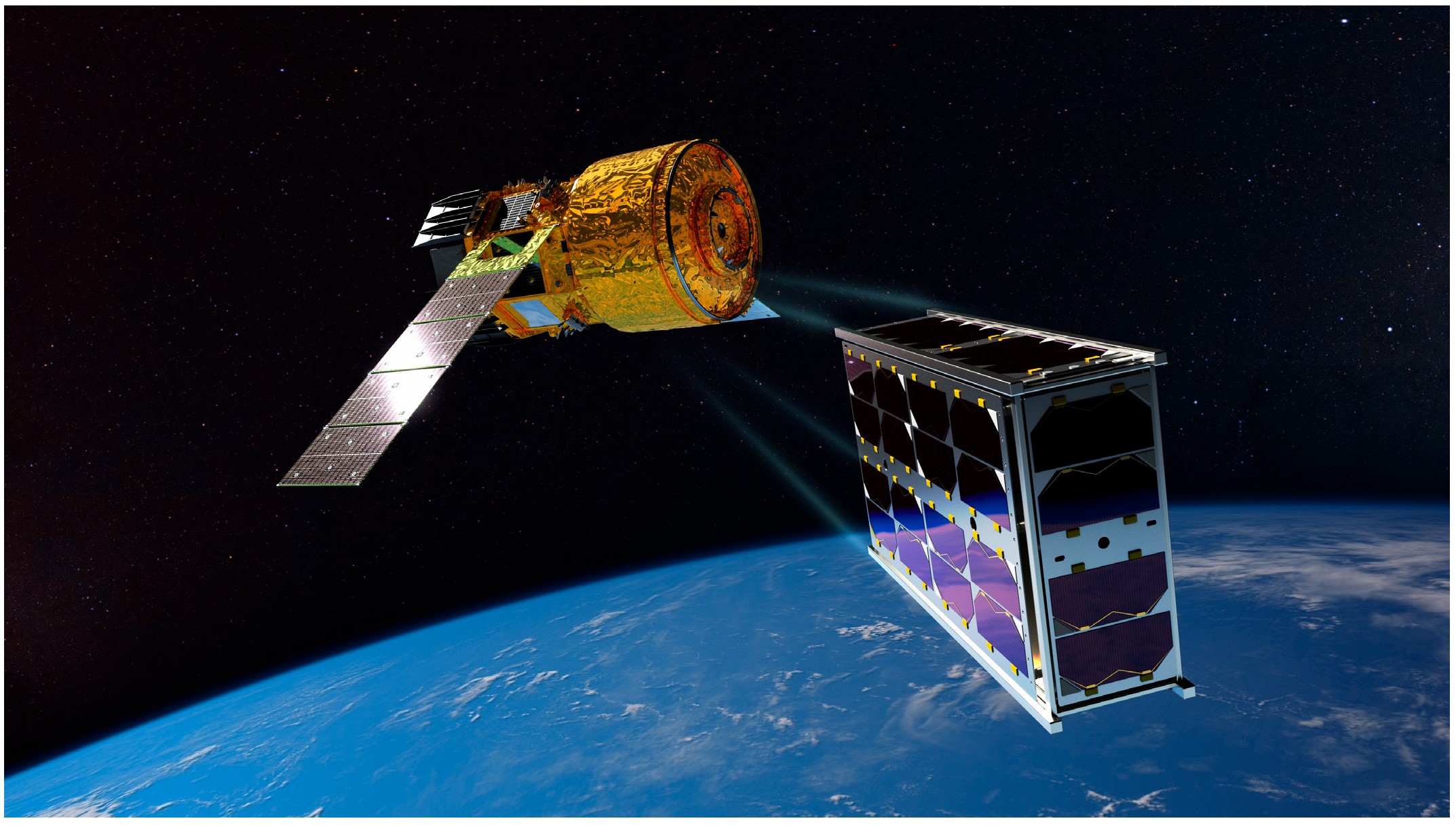
The Japan Aerospace Exploration Agency (JAXA) has been developing the new international space station (ISS) transfer vehicle “HTV-X” which will be launched by a new flagship rocket H3 [8]. This HTV-X is the successor to the HTV, and is intended for in-orbit demonstrations in addition to resupplying supplies to the ISS [8]. In the first HTV-X with the cube satellite (cubesat) release mission [8], the first cubesat to be released from this HTV-X is Ten-Koh 2 (TK2), which the Okuyama Laboratory at Nihon University has been developing [9]. TK2 is a cubesat with a size of wide-6U (366 mm × 226 mm × 100 mm) called a W6U and a mass of approximately 6.8 kg. Both Figure 3 and Figure 4 show the appearances of TK2 which separated from HTV-X.
TK2 is the successor to Shin-en 2 (SE2) and Ten-Koh (TK1). SE2 was launched on 3 December 2014, by H-IIA #26 as a Hayabusa2-sub-payload. It became the first small probe in the world to go beyond the lunar orbit and successfully conduct deep space exploration (measurement of high-energy charged particles) [10,11,12]. TK1 was launched on 29 October 2018, by the H-IIA #40 as a piggyback satellite of Ibuki 2 (GOSAT 2). TK1 was placed in a sun-synchronous quasi-return orbit at an altitude of 610 km. Overviews of SE2 and TK1 are shown in Figure 5 and Figure 6, respectively.
Usually, micro satellite design is performed through a procedure that designs and manufactures a bread board model (BBM), an engineering model (EM), and a flight model (FM). A BBM, an EM, and an FM are developed in the preliminary design, the basic design and the critical design phases, and a FEM is used to thoroughly confirm whether the strength and stiffness requirements are satisfied in each phase. However, since a reliable FEM cannot be obtained at the initial stage of designing a BBM, it is important to establish a simple method to identify the natural frequency. In order to improve this simple identification method, we conducted tests using three micro satellite models. One is the FM of TK2, and another is the EM of Ten-Koh D (TKD). TKD is the successor to TK2 and is scheduled to be launched in 2026. The last one is a dummy satellite made of 100% aluminum alloy and was designed and developed by JAXA.
Table 1 shows the specifications of these three satellites, and overviews of aluminum alloy dummy satellites and the TKD’s EM are shown in Figure 7 and Figure 8, respectively. These three satellite models are equipped with rails that allow them to be jettisoned into space from a small satellite orbital deployer (SSOD) mechanism. Table 1 also lists the sizes without this rail.
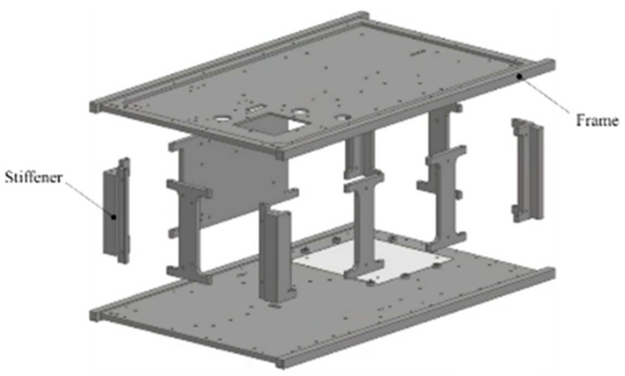
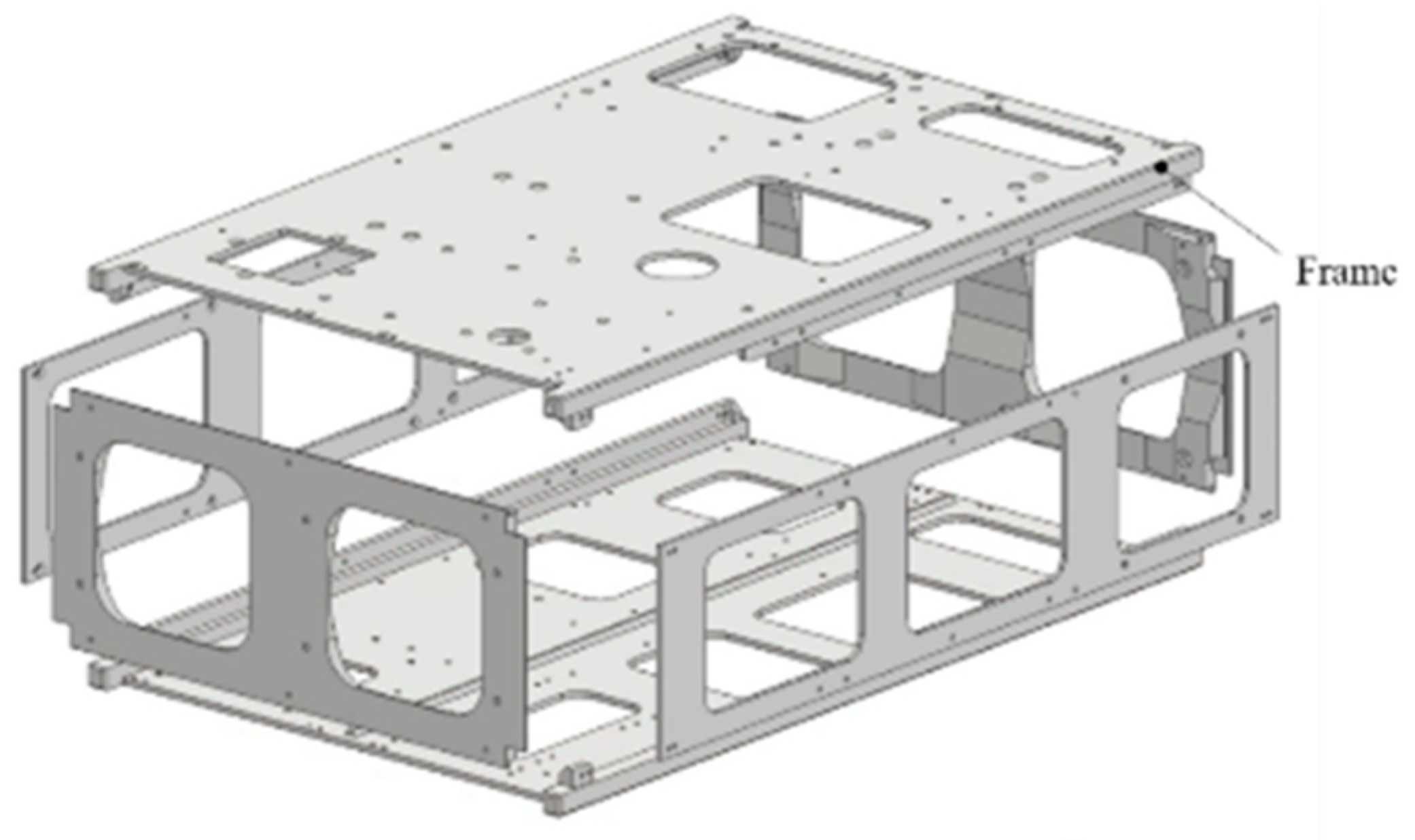
Furthermore, overviews of the primary structure of TK2 and TKD, which are made of aluminum alloy, are shown in Figure 9 and Figure 10, respectively. TK2 and TKD have large internal capacities and have been hollowed out to reduce weight. This type of shape is called a monocoque structure. Monocoque structures have excellent vibration resistance and are often used in the architectural field because they ensure strength. In the field of spacecraft development, this structural style is suitable for satellites because it not only maximizes the capacity of the satellite but also provides a surface for mounting components. The primary structure of TK2 consists of two frames and nine stiffeners. The primary structure of TKD consists of frames on all six sides.
The dummy satellite is also W6U type, and its size is the same as TK2 and TKD. The dummy satellite has six hollow holes with diameters of 73 mm, but it is made only of aluminum alloy.
In order to acquire the minimum natural frequencies of micro satellites, vibration tests were carried out. These vibration tests were mainly done in the advanced technology center for environmental testing of IMV Corporation, Uenohara City, Japan. i260/SA7M/HT10 (HT6) shown in Figure 11 was used for the vibration tests. For this model, the maximum exciting force in a sine wave is 25,000 N, the frequency range is up to 2300 Hz, the maximum random acceleration 700 m/s2 rms, and the maximum payload mass is 138 kg. The vibration tests were carried out based on the standard ISO 17025 [13].

4. Vibration Test Results and Discussions

4.1. Natural Frequencies of Micro Satellites in Longitudinal Direction

Vibration tests of the dummy satellite were conducted, and the test results of the natural frequencies obtained are shown in Table 2. Generally, the aluminum alloys used for the main structure of spacecraft include A5052, A2024 (super duralumin), and A7075 (extra super duralumin), but the density and the Young’s modulus of these three materials are 2680 kg/m3, 2770 kg/m3, and 2800 kg/m3 and 70.6 GPa, 73.5 GPa, and 71.6 GPa, respectively. Since there is no significant difference in the density and the Young’s modulus of these materials, the average values of 2750 kg/m3 and 72.0 GPa were used in this paper. Table 2 also shows the calculated result of the natural frequency for the dummy satellite using Equation (4). This calculated frequency of the dummy satellite agreed relatively well with the measured value obtained in the vibration tests. In the case of the dummy satellite made of 100% aluminum alloy, we understand that the estimation method of Equation (4) is valid. Table 2 also shows the vibration test results for TK2’s FM and TKD’s EM. The masses of TK2’s FM and TKD’s EM are 6.8 kg and 7.9 kg, respectively, and the mass of the aluminum alloy primary structure is 2.2 kg, which is the same value. When this primary structure forms only four sides as a monocoque structure, the thickness will be 3.6 mm, and the area calculated from this will be 2.3 × 10⁻³ m2. In addition, the longitudinal length is uniform at 346 mm. The Young’s modulus was determined using Equation (6), and these values are listed in Table 2. The longitudinal natural frequencies of TK2’s FM and TKD’s EM calculated from these are 430 Hz and 400 Hz, respectively, which agree well with the measured values of 440 Hz and 409 Hz. It can be confirmed from Table 2 that the measured natural frequencies of TK2’s FM and TKD’s EM agree well with the values calculated using Equation (4).
Okuyama et al. conducted vibration tests to determine the natural frequencies using five various cube-shaped micro satellites, the masses of which ranged by approximately 50 kg [3]. These forms were mostly cubes and the lengths of one side ranged from approximately 50 cm. The specifications of the micro satellites used for this testing are shown in Table 2 [3]. Each micro satellite was vibrated in the launch direction (longitudinal direction), and the minimum natural frequencies for each were measured. Okuyama et al. conducted vibration tests on the five cube-shaped micro satellites shown in Table 2 and obtained the minimum natural frequencies in the longitudinal. The measurement results and the calculation results which are computed using Equation (4) are shown in Table 2. The measured values and the calculated values of both domains are in good agreement.

4.2. Natural Frequencies of Micro Satellites in Lateral Direction

The minimum lateral natural frequency of the dummy satellite made of aluminum alloy with six holes with diameters of 73 mm was calculated using Equation (10). The Young’s modulus is the same value used for the longitudinal calculation. The moment of inertia of area was calculated assuming that the aluminum alloy primary structure forms all four sides of the monocoque structure, and these are listed in Table 3. When 11 is entered as the n value in Equation (10), the minimum natural frequency in the lateral direction of this dummy satellite is 1141 Hz, which roughly matches the measured value of 1195 Hz. However, when using 2, 3, and 8 for the n value, the calculated values are 487 Hz, 596 Hz, and 973 Hz, respectively, which are not the same values. When calculating the deflection of the free end of a fixedly supported cantilever beam when a uniformly distributed load is applied to the entire lateral direction, the n value is 8.
Similarly, the minimum lateral natural frequencies of TK2’s FM and TKD’s EM using Equation (10) are the same as 230 Hz, which agrees well with the measured values of 240 Hz and 220 Hz. The n value used in this calculation is 2. This is the n value used to calculate the deflection when a bending moment load is applied to the free end of a fixedly supported cantilever beam.
Okuyama et al. obtained the minimum natural frequencies in the lateral direction of five cube-shaped micro satellites through vibration tests as well as in the longitudinal direction [3]. Table 3 shows the calculated values of the minimum natural frequency obtained by inputting 3 as the n value in Equation (10). These values are in good agreement with the measured values. However, for a satellite with a relatively long longitudinal length of 700 mm, the calculated and measured values are not at the same level, 28 Hz and 43 Hz, respectively. From this, the calculated value of the minimum natural frequency obtained by inputting 8 to the n value in Equation (10) is 47 Hz, which is roughly the same as the measured value.
Rodger Farley expresses the minimum natural frequencies in the longitudinal and lateral directions using Equations (11) and (12):
f n ,   l o n g i t u d i n a l = 1 2 π E A 0.34 m L ,
f n , l a t e r a l   = 1 2 π k m = 1 2 π 3 E I 0.24 m L 3 ,
where L, m, A and I are the length, mass, cross-sectional area, and moment of inertia of area when a satellite housed in a fairing is expressed as a rod. The minimum natural frequency determined using Equations (11) and (12) does not match the experimental values. However, Rodger Farley’s ideas moved our research forward. The difference that existed between Rodger Farley’s equations and ours allowed us to generate the idea of the n value. Calculating the minimum natural frequency using Equation (10), care should be taken in selecting the n value.
Table 4 shows the errors in the calculated and measured values in the longitudinal and lateral directions as percentages. This table shows that when using the method proposed in this study, the calculated values agree with the vibration-tested values within 10%. In particular, in the case of W6U satellites, the two agree within a range of approximately 2% in the longitudinal direction and approximately 5% in the lateral direction. In the early stages of a satellite structure design when a FEM cannot be created, the proposed method will work effectively as the method of determining the minimum natural frequency.

5. Conclusions

Usually, the structural design of micro satellites is performed using the internal stress analysis and the natural frequency analysis, which are based on a FEM. The validity of this structural design is evaluated through vibration tests. In an early stage of development, which has a FEM model of a satellite in the process of creation, presumption of the minimum natural frequency of a satellite may be difficult. In order to simplify the process of the early design stage, a method for determining the longitudinal and lateral minimum natural frequencies of micro satellites during the ascent phase was clarified. The main conclusions are as follows:
  • The W6U-type micro satellites used in this study are the Ten-Koh 2(TK2)’FM and the Ten-Koh D(TKD)’s EM, both of which have monocoque aluminum alloy structures. The W6U-type dummy satellite made entirely of aluminum alloy was also used. Five micro satellites with a mass of approximately 50 kg were also used in this study.
  • In this study, the minimum natural frequency identification method for micro satellites in the launch direction (the longitudinal direction) and its orthogonal direction (the lateral direction) were clearly made using Equations (4) and (10). The n value in Equation (10) is a coefficient for identifying the natural frequency.
  • When the method proposed in this study is used, the calculated values agree with the vibration-tested values within approximately 10%. In particular, in the case of W6U-type satellites, the two agree within a range of approximately 2% in the longitudinal direction and approximately 5% in the lateral direction. In the early stage of a satellite structure design when a FEM cannot be created, the proposed method will work effectively as the method of determining the minimum natural frequency.
  • In this study, 2, 3, 8, and 11 were used as the n values in Equation (10). These n values were thought to be related to the load acting on a fixedly supported cantilever beam, but the details are unknown. This is an important research issue that needs to be solved in the future.

Author Contributions

Conceptualization, K.-i.O.; methodology, K.-i.O. and K.Y.; software, K.-i.O., K.Y., and C.O.; validation, K.-i.O. and K.Y.; formal analysis, K.-i.O., K.Y., and C.O.; investigation, K.-i.O. and K.Y.; resources, K.-i.O.; data curation, K.-i.O.; writing—original draft preparation, K.-i.O., K.Y., and C.O.; writing—review and editing, K.-i.O.; visualization, K.-i.O.; supervision, K.-i.O.; project administration, K.-i.O., K.Y., and C.O.; funding acquisition, K.-i.O. All authors have read and agreed to the published version of the manuscript.

Funding

The Ten-Koh 2 project was funded by the Nihon University College of Science and Technology’s Research Institute for Advanced Research Grants.

Data Availability Statement

The raw data supporting the conclusions of this article will be made available by the authors on request.

Acknowledgments

The Ten-Koh 2 project was carried out under the guidance of JAXA, and the aluminum alloy dummy satellite used in this research was designed and manufactured by JAXA. The Ten-Koh 2 project was conducted under a joint research agreement with Space BD Corporation. In addition, the Ten-Koh 2 project was also carried out in cooperation with Eto Seisakusho Co., Ltd. and Denken Co., Ltd. in Oita Prefecture, and Hibiki Seiki Co., Ltd. in Yamaguchi Prefecture. We would like to express our gratitude to all those involved.

Conflicts of Interest

The authors declare no conflicts of interest.

References

  1. JERG-2-320A; Structural Design Standard. Japan Aerospace Exploration Agency: Tokyo, Japan, 2011. (In Japanese)
  2. JERG-4-011A; User’s Manual of H-IIA Rocket. Japan Aerospace Exploration Agency: Tokyo, Japan, 2015. (In Japanese)
  3. Okuyama, K.I.; Hibino, S.; Matsuoka, M.; Bendoukha, S.A.; Lidtke, A. A Modification of an Estimation Method of the Natural Frequency of a Cubic Form Micro Satellite. Int. J. Res. Granthaalayah 2018, 7, 121–131. [Google Scholar] [CrossRef]
  4. Wijker, J.J. Spacecraft Structures, 2008th ed.; Springer: Berlin/Heidelberg, Germany, 2008. [Google Scholar]
  5. Sarafin, T.P.; Larson, W.J. Spacecraft Structures and Mechanisms: From Concept to Launch, 1995th ed.; Springer: Berlin/Heidelberg, Germany, 1995. [Google Scholar]
  6. Farley, R. Spacecraft Configuration Structural Design-Preliminary Design Methods, Satellite Design Course Material (ENAE691); Department of Aerospace Engineering, University of Maryland, NASA/GSFC: College Park, MD, USA, 2003. [Google Scholar]
  7. Calvi, A. Spacecraft Loads Analysis-An Overview, Satellite Engineering Class Material; Aerospace and Mechanical Engineering; University of Liege, ESA/ESTEC: Liège, Belgium, 2011. [Google Scholar]
  8. Ito, N.; Sasaki, H. Development Status of New Space Station Transfer Vehicle (HTV-X), Council for Science and Technology, Research Planning and Evaluation Subcommittee, Space Development and Utilization Subcommittee; Ministry of Education, Culture, Sports, Science and Technology: Tokyo, Japan, 2021. (In Japanese) [Google Scholar]
  9. Okuyama, K.-I. Rafael Armando RODRIGUEZ LEON, Isai FAJARDO TAPIA and Ten-Koh 2 Team, Completion of the Development of Ten-Koh 2 Spacecraft. In Proceedings of the 33th International Symposium on Space Technology and Science, Kurume, Japan, 3–9 June 2024. [Google Scholar]
  10. Kuroiwa, F.; Okuyama, K.I.; Nishio, M.; Morita, H.; Szasz, B.A.; Bendoukha, S.A.; Saganti, P.; Holland, D. A Design Method of an Autonomous Control System for a Deep-Space Probe. Trans. JSASS Aeronaut. Space Sci. JSASS Aerosp. Tech Jpn. 2016, 14, Pf_105–Pf_112. [Google Scholar] [CrossRef] [PubMed]
  11. Gonzalez-Llorente, J.; Lidtke, A.A.; Hatanaka, K.; Kawauchi, R.; Okuyama, K.I. Solar Module Integrated Converters as Power Generator in Small Spacecrafts: Design and Verification Approach. Aerospace 2019, 6, 61. [Google Scholar] [CrossRef]
  12. Fajardo, I.; Lidtke, A.A.; Bendoukha, S.A.; Gonzalez-Llorente, J.; Rodríguez, R.; Morales, R.; Faizullin, D.; Matsuoka, M.; Urakami, N.; Kawauchi, R.; et al. Design, Implementation, and Operation of a Small Satellite Mission to Explore the Space Weather Effects in Leo. Aerospace 2019, 6, 108. [Google Scholar] [CrossRef]
  13. ISO 17025; General Requirements for the Competence of Testing and Calibrating Laboratories. International Organization for Standardization: Geneva, Switzerland, 2015.
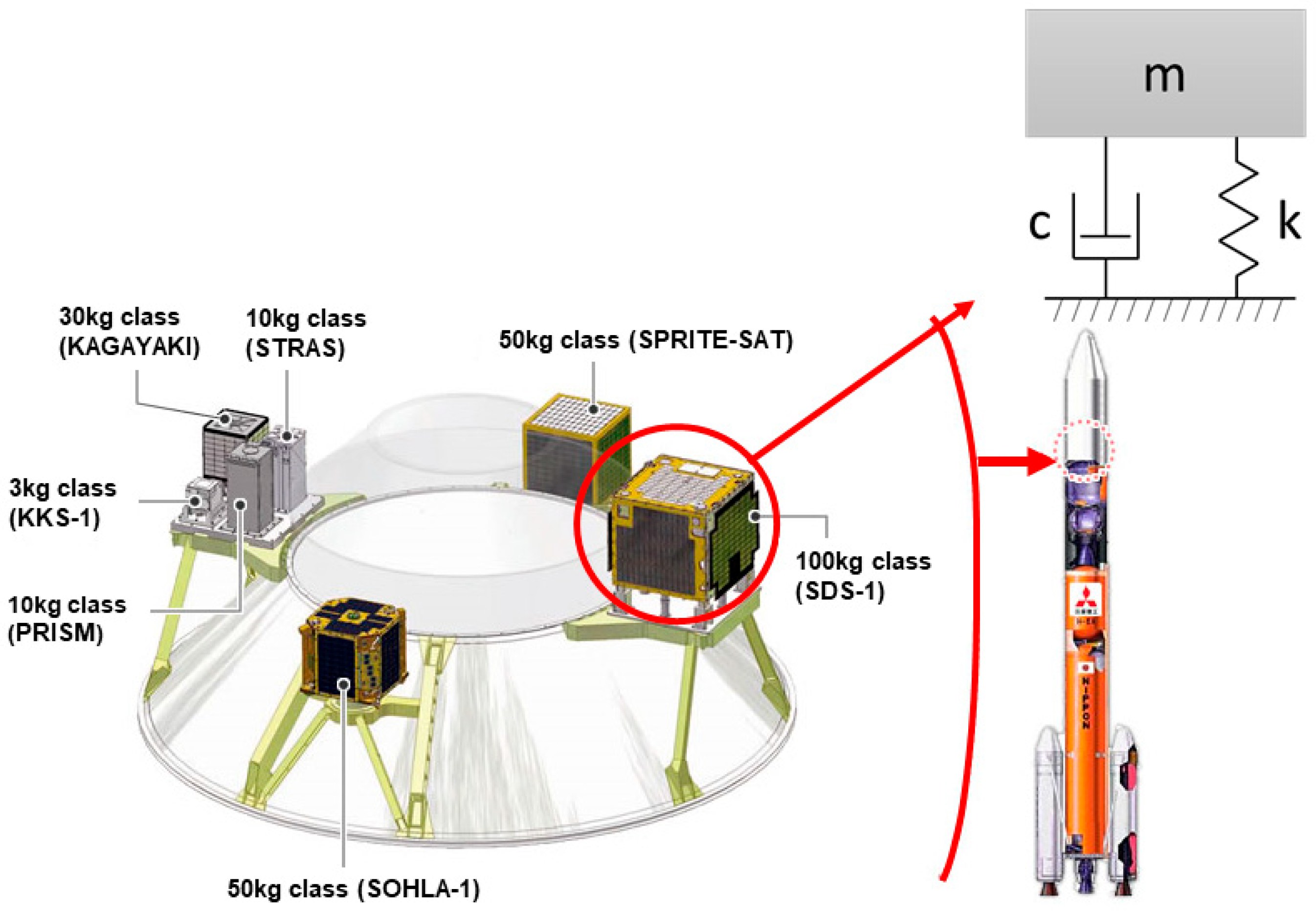
Figure 1. Micro satellites in an H-IIA rocket and a single-degree-of-freedom system.
Aerospace 11 00436 g001
Figure 2. Satellite structure that looks like a rigidly clamped cantilever rod. (a) Structure in which tensile stress is applied in the launch direction (longitudinal direction). (b) Monocoque structure formed only by shells.
Aerospace 11 00436 g002
Figure 3. Appearance of Ten-Koh 2 spacecraft.
Aerospace 11 00436 g003
Figure 4. A 6U satellite separated from HTV-X (©JAXA).
Aerospace 11 00436 g004
Figure 5. Appearance of Shin-en 2 spacecraft.
Aerospace 11 00436 g005
Figure 6. Appearance of Ten-Koh spacecraft.
Aerospace 11 00436 g006
Figure 7. Appearance of the dummy satellite.
Aerospace 11 00436 g007
Figure 8. Appearance of Ten-Koh D’s EM.
Aerospace 11 00436 g008
Figure 9. Primary structure of Ten-Koh 2’s FM.
Aerospace 11 00436 g009
Figure 10. Primary structure of Ten-Koh D’s EM.
Aerospace 11 00436 g010
Figure 11. Appearance of i260/SA7M/HT10 (HT6) located IMV corporation.
Aerospace 11 00436 g011
Table 1. Specifications of aluminum alloy dummy satellites, Ten-Koh 2’s FM, and Ten-Koh D’s EM.
Specimen NameAluminum AlloyLength with Rail ×10−3 [m]Length without Rail ×10−3 [m]Mass [kg]Shell Thickness ×10−3 [m]Cross-Sectional Area
×10−3 [m2]
Young’s Modulus [GPa]Density [kg/m3]LhbLhbWhole SatelliteStructural SubsystemAlateralAs
Dummy satellite72275036622610035521510014.114.122.922.614.4
TK2’FM7227503662261003552151006.832.253.6522.62.30
TKD’EM7227503662261003552151007.892.253.6522.62.30
Table 2. Minimum natural frequency in the launch direction (longitudinal direction).
Specimen NameLength without Rail ×10−3 [m]Mass [kg]Shell Thickness ×10−3 [m]Cross-Sectional Area
×10−3 [m2]
Young’s Modulus [GPa]Minimum Longitudinal Natural Frequency [Hz]
LlongitudinalhbWhole SatelliteStructural SubsystemtAlateralAsEsCalculated ValueMeasured Value
Dummy satellite35521510014.114.122.922.614.44818801927
TK2’FM3552151006.832.253.6522.62.357.7430440
TKD’EM3552151007.892.253.6522.62.357.7400409
CubeSat150050050045.717.26.2525.012.53.6223209
CubeSat255050050057.618.96.2525.012.53.6190186
CubeSat370050050064.824.16.2525.012.53.6158144
CubeSat450050049043.916.86.1924.512.33.6226207
CubeSat552052050060.018.66.3726.013.03.6195170
Table 3. Minimum natural frequency in the launch orthogonal direction (lateral direction).
Specimen NameLength without Rail ×10−3 [m]Mass [kg]Moment of Inertia of Area ×10−6 [m4]n ValueMinimum Lateral Natural Frequency [Hz]
LlongitudinalWhole SatelliteStructural SubsystemIlateralCalculated ValueMeasured Value
Dummy satellite35514.114.160.91111411195
TK2’FM3556.832.2513.62230240
TKD’EM3557.892.2513.62230220
CubeSat150045.717.2501356.555
CubeSat255057.618.9501346.747
CubeSat370064.824.1501847.143
CubeSat450043.916.8489356.463
CubeSat552060.018.6559354.153
Table 4. Errors in calculated and measured minimum natural frequencies in the longitudinal and lateral directions.
Specimen NameMinimum Longitudinal Natural FrequencyMinimum Lateral Natural Frequency
Calculated Value [Hz]Measured Value [Hz]Errors in Calculated and Measured Values [%]n ValueCalculated Value [Hz]Measured Value [Hz]Errors in Calculated and Measured Values [%]
Dummy satellite188019272.4411114111954.52
TK2’FM4304402.2722302404.17
TKD’EM4004092.222302204.54
CubeSat12232096.7356.5552.72
CubeSat21901862.15346.7470.64
CubeSat31581449.72847.1439.53
CubeSat42262079.18356.46310.5
CubeSat519517014.7354.1532.08
Disclaimer/Publisher’s Note: The statements, opinions and data contained in all publications are solely those of the individual author(s) and contributor(s) and not of MDPI and/or the editor(s). MDPI and/or the editor(s) disclaim responsibility for any injury to people or property resulting from any ideas, methods, instructions or products referred to in the content.