Article

Performance and Reliability Evaluation of Innovative High-Lift Devices for Aircraft Using Electromechanical Actuators

by
Carlos Cabaleiro de la Hoz
1,2,*,
Marco Fioriti
2 and
Luca Boggero
1
1
German Aerospace Center (DLR), Institute of System Architectures in Aeronautics, Hein-Saß-Weg 22, 21129 Hamburg, Germany
2
Department of Mechanical and Aerospace Engineering (DIMEAS), Politecnico di Torino, Corso Duca degli Abruzzi 24, 10129 Turin, Italy
*
Author to whom correspondence should be addressed.
Aerospace 2024, 11(6), 468; https://doi.org/10.3390/aerospace11060468
Submission received: 27 March 2024 / Revised: 30 May 2024 / Accepted: 5 June 2024 / Published: 11 June 2024

Abstract

:
In the last decades, electromechanical actuators started to be introduced in transport aircraft for primary and secondary flight control surfaces. Some innovative architectures have been proposed in the literature to use these actuators for high-lift devices (flaps and slats). The state-of-the-art architecture is built with a central mechanical shaft powered by a power distribution unit connected to ballscrew actuators that actuate the flap and slat surfaces. New innovative concepts have the potential to improve the state-of-the-art architectures. However, there is a lack of quantitative results for such innovative architectures. A new methodology is proposed to preliminarily estimate performance and reliability aspects of conventional and innovative architectures. This allows quantitative comparisons to finally be obtained. The methodology is applied to a new architecture that uses electromechanical actuators for flaps and slats, providing results in terms of performance and reliability and comparing them to the current state-of-the-art high-lift devices. Results show that the new architecture is lighter than the reference one and can be more reliable. This is achieved thanks to the removal of the mechanical links among components, which allows each control surface to be deployed independently from the others. This highly increases the operational reliability of the system. Two cases are analyzed, with and without actuator jamming. This provides more realistic results since this failure mode is currently the main reason why electromechanical actuators are not being used for more applications. The innovative architecture outperforms the conventional one in the case where the electromechanical actuators are not affected by the jamming failure mode.

1. Introduction and State of the Art

The flight control system (FCS) guarantees precise and safe flight control of the aircraft. It can be subdivided into primary and secondary flight controls [1]. Primary flight controls are used to command the aircraft in flight through pitch, roll and yaw control. They are constantly active during the whole mission [2]. For commercial aircraft, they include the rudder, ailerons and elevators. Secondary flight controls are only used in some specific segments of the mission profile (e.g., approach, landing, take-off, etc.). Their main function is to momentarily modify the wing geometry to increase lift and/or drag [2]. For commercial aircraft, they consist of spoilers, flaps and slats. Flaps and slats are also commonly called high-lift devices. In military vehicles, some surfaces can be merged, serving more than one purpose. For instance, flaperons can be used as flaps or ailerons [1].
This paper focuses on high-lift devices for commercial aircraft. State-of-the-art high-lift devices predominantly consist of a mechanical transmission shaft connected to ballscrew actuators that deploy the surfaces [3,4]. Power is provided by a central power drive unit (PDU) that is connected to the main shaft through some gearboxes [5]. The shaft is mechanically connected to each of the actuators that deploy the flaps and slats synchronously and symmetrically. PDUs can be powered hydraulically or electrically, depending on the components involved, and can also be single or dual depending on the number of motors per unit [6,7]. Actuators are usually linear ballscrews [7].
Maintaining symmetry during the deployment of high-lift devices is key since it is obligatory to neutralize asymmetries in flight [7]. Conventional high-lift devices have the previously mentioned mechanical main shaft that connects all the actuators. If this shaft breaks, one part of it remains mechanically disconnected from the rest. This effect can create unwanted asymmetries. Wing tip brakes (also called torque limiters) are used for this purpose [7]. When the mechanical transmission breaks, the monitoring and control system activates the friction disks inside the wing tip brakes. This generates the proper torque to brake the disconnected part of the system and keep it fixed in its position [7]. This type of architecture assures a synchronous deployment of all flap and slat panels but also involves a high number of components of different types, which requires a specific design effort [3].
Figure 1 shows a detailed schema of the state-of-the-art architecture for flaps. Each flap surface is deployed by two actuators that are connected to the main shaft through the correspondent gearboxes. Two extra gearboxes per wing are typically located between the power drive unit and the first actuator in order to redirect the main shaft through the fuselage and wing [5]. Two torque limiters are located at the wing tips. All actuators are linear ballscrews. State-of-the-art slats are built following the same schema. A specific figure for slats is avoided to avoid unnecessary repetition. The only difference is that slats have a larger number of surfaces. Following the example in Figure 1, the slats have ten slat surfaces (five per side) instead of four flat surfaces (two per side). The rest remain the same, which means that there is one main PDU, two ballscrew actuators per surface and two torque limiters in total.
This reference architecture is currently being used in most commercial aircraft. New promising flap geometries are being explored [8] in order to achieve fuel burn reductions. New actuators are bringing new possible concepts that might also bring promising results. Electromechanical actuators (EMAs) give the ability to remove the central power unit and main shafts. These actuators have their own individual servo motor, and, as a result, they do not need all the central devices providing torque [9]. They also do not need any central hydraulic line providing power as classic hydraulic actuators do. Linear ballscrew actuators can directly be substituted by linear EMAs. However, this substitution creates a new issue. Torque limiters cannot be used to avoid asymmetries since the central mechanical shaft does not exist in this architecture. This is solved with the addition of electronic devices that can deactivate the corresponding motors when a failure is detected. This architecture was suggested in [3]. A fully independent flap actuation system is designed with an EMA located at each drive station without needing a transmission shaft linkage between the different stations. Synchronous deployment is guaranteed thanks to actuator control electronics and slat/flap control computers. They assure a synchronous deployment of both symmetric actuators of each flap panel, hence, avoiding skew or twist of the flap panel. The same architecture was further analyzed in [10], where a more detailed design is provided. The EMA is built with an internal permanent magnet brushless DC motor that transforms the electric power into motion directly. A ball-nut assembly is used. According to the authors, the proposed architecture is able to “fulfill the fault-tolerant requirements and it is suitable for high reliability flap application”. This architecture was also briefly commented on in [6], where different strategies are utilized for the central power drive units of the conventional concept.
Figure 2 shows the scheme of this innovative architecture with all the components involved. It can be seen how the central components (i.e., main shaft and PDU) disappear. Now every flap surface is independent from the others. Each surface still has two actuators connected to it; however, these actuators are now electromechanical ones. The ballscrew actuator, motor and power control electronics are condensed into one single component or unit. Two of these units are present per flap surface, and each of these couples requires an actuator control electronics (ACE) unit. This unit guarantees correct and symmetrical deployment of the flap surface, avoiding panel twisting. These units are connected to the flap/slat control computers, which allow communication among all ACE and ensure that asymmetries are neutralized. As for the conventional architecture, slats are built in the same way as flaps. The only difference resides in the number of slat surfaces. Flaps have four flap surfaces (two per side); slats typically have ten slat surfaces (five per side). Each slat surface is also composed of two EMAs, each of them connected to their correspondent PCE, both connected to ACE. A specific image for slats is avoided since it is redundant, and the only difference compared to Figure 2 is the number of surfaces (four compared to ten).
The differences between the conventional architecture (Figure 1) and the innovative one (Figure 2) can easily be seen when comparing both figures visually. The transition from mechanical components to electronic ones is noticeable. This new concept of electrifying the system is known as the more-electric aircraft (MEA) tendency. Its main idea is to replace hydraulic, pneumatic and mechanical on-board systems with electrified versions. This carries some benefits such as reducing the aircraft mass, fuel consumption and emissions [11]. Some challenges that arise are the increase in the electric system complexity, dealing with challenges such as performance in harsh environment, mass optimization, safety and types of failures [12].
Furthermore, this new architecture could potentially reduce the mass of the high-lift devices and bring some other benefits. However, safety issues do not allow it to be utilized. This mainly comes from the jamming failure mode that the EMAs have. There are typically two actuators per flap or slat surface in redundancy. If one actuator fails, the other can still deploy the surface. This increases the reliability. Jamming is a failure mode that can occur when EMAs are used. This failure mode jams the actuator, blocking its position, and, as a consequence, the whole flap or slat surface. Even if the redundant actuator is available, it cannot successfully deploy the high-lift device surface. This failure mode cancels the redundancy and reduces immensely the reliability of the system. This is currently the main drawback of EMAs and the main reason they are not being used in safety-critical components [13]. However, some current studies are progressing towards jamming-free actuators that might actually increase reliability if they are successfully achieved [14].
The main question is as follows: how can EMAs actually increase reliability? This comes from the effect of removing the central mechanical shaft. As explained before, if the main shaft breaks or the PDU fails or one gearbox breaks, the whole system needs to be stopped to avoid asymmetries. Torque limiters assist in this function. This does not happen in the new EMA concept since the central devices are not present anymore. In fact, focusing now on the flap case, this new architecture presents a new scenario that was not possible before. It allows the deployment of just one of the two flap surfaces (i.e., the inboard flap and outboard flap). It is important to mention that this deployment is always symmetrical. An example is provided to the reader. If one of the inboard flaps fails (e.g., due to the jamming of one actuator), the other symmetric inboard flap can be stopped in the same position thanks to the electronic devices commanding the actuators. Both outboard flaps can still be fully deployed. The same happens when switching inboard and outboard surfaces. This scenario is not possible in the state-of-the-art architectures. Here, a failure of one actuator or a gearbox would immobilize the transmission shaft, resulting in the complete loss of the flap system. Consequently, the new EMA concept could potentially highly increase the reliability of the system. This idea was already presented in previous studies [3]. Here, the authors state that, owing to the complete independence among all flap panels, the aircraft can now be operated with only one flap pair. This would “increase operational reliability” [3]. However, one important factor discussed is that the wing would need to be designed considering this scenario; a direct retrofit of the system would not be possible as a result. Consequently, this system would need to be considered in the early stages of design in order to fully exploit its potential, affecting the design of the wing. The importance of assessing such disruptive technologies starting from the preliminary design phase was highlighted in [15], where it is stated that this is important in order to achieve significant impact in aviation reductions. For this case, assuming the change in the wing design might seem excessive, but such a change might not be far from the future reality.
The difference in failure rates among the conventional and innovative architecture is further explained in this paragraph. For the conventional architecture, a failure of one single component (e.g., PDU or shaft) can result in the inability to operate the whole flap or slat system. This condition is not critical to the flight safety [7]. However, big asymmetries between the left and right surfaces are critical, and this can come from an uncontrolled shaft fracture [7]. For this reason, the most used architecture employs reversible actuators with wing tip brakes and a central PDU, usually with a dual motor to increase reliability. Regarding the more-electric architecture with EMAs, the jamming failure is now present and needs to be accounted for. However, the management of the mechanical jamming is still an open issue for EMAs; it probably represents the biggest barrier to the usage of EMAs for safety-critical functions [9]. For this reason, they are not being used in primary surfaces, although they could be used for low-power applications [16]. Some studies have tested this failure mode, and it is actually not a frequent failure mode [9,17]. However, it still compromises the control surface, and, hence, it will be further investigated before being introduced in aircraft. On the other hand, in order to better understand the differences with the conventional architecture, a comparison with a shaft failure is performed. One study calculated experimentally the failure rates of this main shaft for a slat system [18]. They conclude that transmission shaft fracture and motion seizure are the main failure modes in the system. They also statd that, from 1956 to 2004, more than 40 accidents were caused by slat mechanism failure. This initiates a hypothesis that implies that shaft fracture in conventional high-lift devices might be more common than jamming in EMAs. This would result in positive expectations about the innovative architecture. Another key factor that needs to be addressed is the maturity level of the EMAs in order to better clarify how realistic the new concept is. Although they are not used in safety-critical devices, EMAs are currently used in aircraft for different purposes. The B787 uses EMAs for spoiler actuation and horizontal stabilizer trim actuation [13]. Some military vehicles also use this technology such as the X-33 or F16 [13]. The A350 and A380 use EMAs in the thrust reversal [16]. Therefore, this technology is not far from reality.
Jamming is not the only new failure mode introduced by the EMAs, although it is the most dangerous. These failures are, in general, quite different from the ones seen in conventional actuators. The design and development of EMAs involve new challenges such as the high integration of the motor and bearings, lubrication in severe environments, load measurement, optimized thermal sizing, standards for software/hardware, embedded compact power electronics, health monitoring of all critical parts, etc. [12]. However, other studies ensure better benefits for the EMAs, having, for example, lower failure rates in general or better behavior under adverse environmental conditions [4].
As a result, with a certain level of speculation, the introduction of EMAs for high-lift devices is not far from reality provided that anti-jamming technologies are successfully developed (i.e., successful jamming mitigation techniques [19] or anti-jamming EMAs, where the actuator is capable of operating after a mechanical jamming [14]). The implementation of this new architecture might bring some benefits. The removal of the central mechanical devices reduces some inefficiencies [13]; as a result, each actuator is sized more optimally. The reduced number of components might reduce the overall weight of the architecture and leave more volume and space to other systems [20]. Even a reduction in the number of maintenance tasks is expected [20], as well as a possible reduction in the manufacturing effort [3], shortening the production time [13]. The addition of extra electronic devices must be addressed, but this effect is expected to have low impact. Some studies are even progressing towards more reliable EMAs [21].
The main objective of this manuscript is to develop a methodology that allows quantitative results for the conventional and innovative high-lift device architectures to be obtained. This can provide a better insight into how feasible the innovative concept is. The focus of this study is limited to evaluating the difference in terms of performance and reliability. Performance is the first discipline to check in order to decide whether or not a new technology might have potential. Differences in mass and power affect the overall aircraft mass and fuel consumption. Reliability is also assessed since it is the current limiting factor for the introduction of EMAs in aerospace systems. Differences in probability of failure determine whether the innovative architecture is safer than the state-of-the-art one. Other disciplines such as maintenance or manufacturing should be further analyzed to fully understand the potential of the new concept. Several tools are used for the evaluation of performance; they are fully explained in Section 2. For the reliability estimation, the reliability block diagram technique is used. This was suggested by previous studies [22]. A dedicated tool is created and used for its solving which is based on the RBD standards [23]. The innovative aspects of these methodology are now highlighted:
  • Safety is a current limiting factor for EMAs. This methodology provides a means to preliminarily estimate the reliability of an architecture. Such estimation can provide conclusions about the feasibility of a new architecture. Furthermore, the methodology can be replicated for other systems;
  • The RBD has not been used before to evaluate these architectures. This technique is supported by standards and can provide quick and meaningful estimations for preliminary reliability analysis. The main limitation lies in the estimation of the failure rates of the components. This can be solved by obtaining such values from databases or feedback from industry;
  • The methodology is able to assess the impact of the EMAs when used in a real architecture, including the effect of additional components and not stopping on an actuator level. This allows the consideration of added effects and has more realistic results. This applies to both disciplines. Regarding performance, some previous analyses compared the mass of ballscrew actuators and EMAs, but no results for the whole system were provided. Regarding reliability, some studies analyzed the EMA failure rates but not the behavior of the architecture as a whole. This manuscript provides a solution for both disciplines, providing a method to assess the overall effect of the architecture as a whole.
Summarizing, this paper provides a methodology and applies it to two architectures of interest (i.e., one conventional and one innovative) for flaps and slats. The results provided have a low technology readiness level (TRL) but serve as a starting point for further higher-fidelity studies. The most important outcome of this analysis is to finally provide a means to obtain quantitative results for the new innovative architecture and not just qualitative speculation based on experience. The results show promising advantages and benefits if the anti-jamming EMAs are successfully achieved.

2. Materials and Methods

Two different disciplines are quantitatively evaluated in this analysis: performance and reliability. The performance of an on-board system can be synthesized by the mass, power off-take and bleed requirement. All these have an impact on the maximum take-off mass of the whole aircraft and must be accounted for. The reliability can be assessed by evaluating the probability of failure of the system. Both disciplines are further explained in the following subsections.

2.1. Performance

The performance of a subsystem can be summarized by the system mass, power off-take and bleeding required. These parameters together affect the aircraft sizing [11]. The system mass directly affects the aircraft mass, and the correspondent increase or decrease in the structural elements must also be accounted for. For this reason, the analysis should not be stopped at subsystem level, and the effect on the whole aircraft must be accounted for in order to fully understand the potential of new architectures. The power required by a subsystem is called power off-take, and it directly affects the engine. This power is typically extracted by electric generators and hydraulic pumps; a higher power demand requires a higher power extraction from the engine. The same effect happens with the air bleeding. Higher bleeding penalizes the engine fuel consumption more, while no bleeding at all lets the engine perform without penalties. This translates into a better specific fuel consumption that has an impact on the maximum take-off mass and fuel burn [11]. For the evaluation of this study, the following framework is proposed:
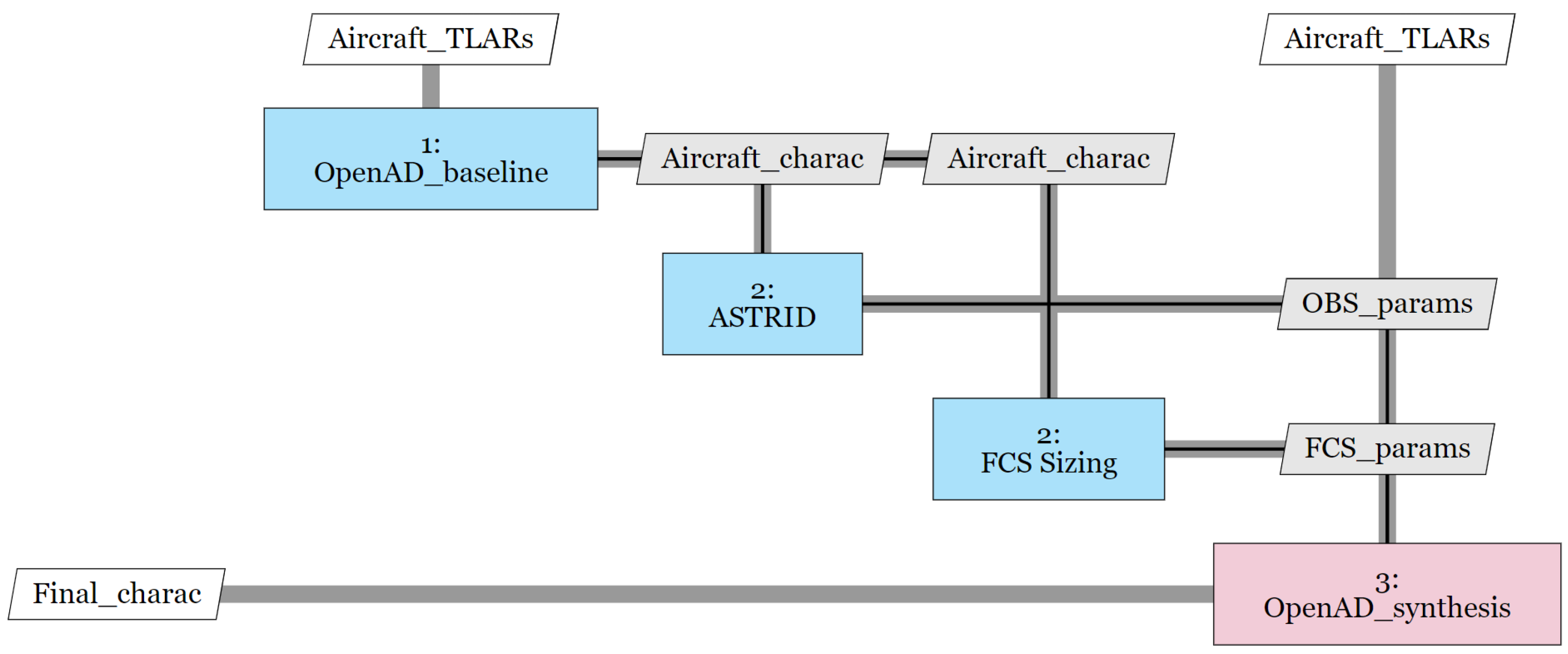
  • Aircraft baseline generation: Some top-level aircraft requirements are defined, and, from them, the aircraft is preliminarily sized. This provides some estimation for the masses and geometry of the aircraft that are needed for the posterior steps (i.e., aircraft characteristics). This is performed by OpenAD, a DLR in-house tool for aircraft design [24]. This tool is explained with more details in Section 2.1.1;
  • On-board systems evaluation: The systems can be designed after the preliminary sizing of the aircraft. For this, ASTRID is used [25]. It is a tool developed at Politecnico di Torino that allows the on-board systems with different levels of electrification to be sized. It provides the masses, power off-takes and bleed needed by each of the on-board systems (OBS) considering all power-consuming, power generation and power distribution systems. For more details about this tool, the reader is referred to Section 2.1.2;
  • Flight control system sizing: This can be carried out with ASTRID; however, this tool does not reach the component level required for this analysis, and, consequently, a dedicated tool is developed for this subsystem. This specific tool is based on the study shown in [5], which can provide component-level estimations based on high-level information. It is further explained in Section 2.1.3. This tool is run after ASTRID and updates the results of the flight control system, specifically in terms of mass and power;
  • Aircraft synthesis: Another aircraft sizing iteration is performed after the on-board systems are sized. The same top-level aircraft requirements (TLARs) are used, but new additional information is added (i.e., OBS mass, off-takes and bleed). As a consequence, a more precise and refined result is obtained, and the snowball effect is accounted for, which is explained in the results section with some examples. This analysis is again performed with OpenAD [24]. Another OBS sizing iteration could be added but does not really add value since the difference in results that is observed is minimal (less than 0.5% of variation in MTOM).
All these steps are represented in Figure 3 as an extended design structure matrix. Blocks represent the tools, vertical lines indicate the inputs and horizontal ones the outputs. Thanks to this diagram, the user can quickly understand how the information is exchanged among the different tools and what the running order is. The whole workflow starts from block 1. Some TLARs are given as input to an overall aircraft design tool (OpenAD in this case, but other tools can be used). The results are the aircraft characteristics such as an initial MTOM, wing surface, fuselage length, engine thrust, etc. These results allow the on-board systems to be sized more precisely. ASTRID is used for this purpose and provides as a result the masses, power off-takes and bleed for the given architecture in the given aircraft baseline. The dedicated FCS tool works the same way but is focused only on this system. Once all the masses, off-takes and bleed are summarized, they can be given back to OpenAD. This provides a more precise aircraft baseline with higher-fidelity results based on the specific OBS architecture. Consequently, values such as the final MTOM or fuel burn can be obtained for each of the architectures.

2.1.1. Overall Aircraft Design—OpenAD

An overall aircraft design tool is required to properly size the aircraft in which the systems are installed. The main input in this analysis is a list of requirements specified in an input file. These requirements (i.e., TLARs) include some fixed values such as the number of passengers, range, cruise Mach number, take-off distance, etc., and other initial estimations of some parameters to help with convergence, for instance, an initial MTOM, wing load, wing and tail characteristics such as dihedral angle, aspect ratio or taper ratio, etc. OpenAD [24] is used in this manuscript. However, any other overall aircraft design tool can be used for this purpose. In this study, the tool is used to generate a baseline for the A320neo. The input mentioned previously is known, and the output consists of a detailed model of the aircraft including different results for different disciplines (e.g., aerodynamics, geometry, structure, masses, fuel burn, etc.). OpenAD is based on well-understood handbook methods (i.e., Torenbeek, Raymer, Rosskam, Jenkinson). The reader is referred to [24] for more details. In this reference, the reader can find further information about the mass and center of gravity analysis, aerodynamic modeling, geometry definition, engine performance modeling and mission fuel calculation.

2.1.2. On-Board Systems Sizing—ASTRID

This manuscript focuses on aircraft high-lift devices. To evaluate the impact of one system, it is crucial to consider how it affects the other systems, such as the distribution systems. As a consequence, a detailed design of the on-board systems is required to increase the fidelity of the results. For this purpose, ASTRID is used [25]. This tool takes as input several parameters that come from the aircraft design analysis, such as MTOM, wing shape, fuselage dimensions, number of passengers or the engine characteristics. As output, it provides an estimation of the mass, power off-take and bleed required by each of the OBS. The tool is sensitive to more-electric architectures, which improves the fidelity of the results. For more detailed information on the equations behind ASTRID, the reader is referred to [27]. This reference presents the base methods behind the tool, although more refined models are used for the more-electric version of some systems, such as the environmental control system [28]. This tool was calibrated and validated in previous studies. The more-electric and all-electric architectures were analyzed for a 19-passenger aircraft in [11]. Other aircraft sizes were also studied and calibrated. Results for a business jet can be found in [29]. Results for a 90-passenger aircraft are disseminated in [30].

2.1.3. Flight Control System Sizing

The flight control system is sized following the methodology presented in [5]. This allows a component-level estimation to be reached starting from only some TLARs (i.e., maximum take-off weight, wing surface, fin surface and cruise Mach). First, the methodology provides a surrogate model to estimate the hinge moments and forces for each control surface. Afterwards, it provides equations to calculate the components mass for each surface, as well as the power required. Hinge moments and actuator masses are aligned with those presented in [31]. The actuator masses are calibrated with the models in [32]. However, the mass of the new components of the innovative architecture is missing. EMAs can be sized following the equations in [5]. An extra calibration from another source is performed in order to further validate the methodology for innovative architectures. The stall load and mass of a real EMA from the 1990s are specified in [13]; the exact values provided are 133 kN and 36.3 kg, respectively. If this value of stall load is introduced in the equations provided in [5], the result is a mass of 39 kg. This difference of just 3 kg between the model and the real actuator is considered minor; hence, the results from the methodology can be assumed reliable. The electronic devices are more difficult to estimate since they are not present in the methodology previously mentioned. However, a mass breakdown of an EMA is presented in [16]. Here, the power electronics constitute 12% of the mass of the whole EMA. These electronic devices are included in the actuator mass, but the actuator control electronics are not (difference can be seen in Figure 2). In order to consider these additional ACE in the model, an extra 10% increase in mass is added after estimating the weight of the EMAs.

2.2. Reliability

The reliability block diagram technique is chosen in order to estimate the reliability of an architecture [22]. This allows the architectures to be quantitatively and easily evaluated, unlike other safety-evaluating methods such as failure tree analysis or failure mode and effects analysis, which require further information that is not available at this stage of design [33]. The reliability of a component can be estimated from its failure rates, as shown in Equation (1):
R c o m p o n e n t = e λ t ,
where R represents the reliability, λ the failure rates of the component and t the time. If the failure rates are considered as failures per hour, the reliability can be obtained also per hour, eliminating the time variable. The correspondent reliability block diagram (RBD) can now be built and evaluated for each architecture. The RBD configuration is defined by the architecture of the system, that is, the components and connections among them. Components are typically in series or parallel depending on their functionality. Other non-conventional configurations among components can be found [22]; however, they are not needed in the architectures evaluated in this study. The RBDs for each high-lift device architecture are shown in the results section, where all components are in series or parallel. Equations (2) and (3) are used in order to solve the RBDs.
R s e r i e s = i = 1 n R i ,
R p a r a l l e l = 1 i = 1 n ( 1 R i ) ,
The reliability of the system is obtained once the RBD is reduced into one single component [23]. Since the reliability value is usually quite high (i.e., almost one but not one), an alternative is suggested to be able to better see the differences among architectures. The probability of failure is used. It can easily be estimated as one minus the reliability. This provides an easier comparison and a more representative value for the results. Both values (i.e., reliability and probability of failure) are used in this analysis as units per hour. Summarizing, with only the architecture of the system and the failure rates of each component, it is possible to obtain a proper estimation of the probability of failure of that system by using the reliability block diagram technique.

3. Results and Discussion

The results for both disciplines (i.e., performance and reliability) are presented in this section. Two different OBS architectures are evaluated (i.e., conventional and all-electric architectures). Both architectures are integrated into the same baseline, generating two different aircraft. The common baseline is based on the A320neo; one aircraft has conventional on-board systems and the other an all-electric version of them. Two different high-lift device architectures are evaluated; this generates a total of four alternative configurations: conventional with conventional high-lift devices, conventional with EMA high-lift devices, all-electric with conventional high-lift devices and all-electric with EMA high-lift devices. The main parameters of the baseline aircraft (A320neo) are represented in Table 1.
These TLARs represent the aircraft baseline and are used in the following subsections as a starting point to generate the results. Section 3.1 shows the results in the performance discipline, while Section 3.2 contains the results for reliability.

3.1. Performance

As explained before, four different aircraft are analyzed. For that, a common baseline is needed. It is generated with OpenAD [24] using the TLARs (main ones represented in Table 1). Then, the on-board systems can be sized and installed using ASTRID [25]. Two OBS architectures are analyzed: conventional and all electric. As a result, two different outputs are obtained. Both architectures are now further explained. The conventional architecture for the on-board systems consists of avionic equipment capable of transoceanic flight, conventional hydraulically actuated flight controls, a hydraulically actuated landing gear, conventional high-lift devices powered by a hydraulic PDU, a pneumatic ice protection system for nacelles, a wing, a vertical tail and horizontal tail, a conventional environmental control system with a three-wheel high-pressure bootstrap cycle, a fuel system powered by electric pumps and three power distribution systems which are pneumatic, hydraulic and electrical. The architecture of the all-electric concept changes some of the subsystems. Flight controls and high-lift devices switch to electric actuators (EHAs for primary control surfaces and spoilers, EMAs for high-lift devices), but this will be analyzed more in depth later. The landing gear uses electromechanical actuators for retraction, steering and braking, managing to completely remove the hydraulic components. The ice protection system is based on electro-thermal blankets (as in the B787) for all the surfaces. The environmental control system passes to a bleed-less concept in which the air is compressed by two external compressors, hence not needing to perform bleeding to the engines. The rest of the OBS stay the same. However, it can be noticed how two of the distribution systems are not needed anymore. This architecture concept manages to fully eliminate the hydraulic and pneumatic systems, relying on a fully electric power distribution system. Results from ASTRID are shown in Table 2.
It is noticeable how some systems grow in mass when moving to an all-electric concept. However, the removal of the hydraulic and pneumatic systems fully compensates this effect. The following question may arise: why does the electrical system not grow in mass since now there are more electrical users and, hence, the power requirement is higher? This comes from the fact that the conventional architecture is based on generation at 115 Volts in alternate current with integrated drive generators. The all-electric concept integrates a new technology that allows generation at 230 Volts in alternate current at variable frequency. This increase in voltage allows the size of some components to be reduced (e.g., transformers, rectifiers, power distribution units, cables, etc.), and, as a result, the overall effect has almost the same weight as the conventional concept while having a higher power budget.
The main issue is that ASTRID is not able to analyze the high-lift device architecture represented in Figure 2. The scope of this study is to reach component level to fully understand the differences in terms of mass and where they come from. For this reason, a specific tool for flight control system sizing is developed, as explained in Section 2. This tool is capable of analyzing the following four different architectures:
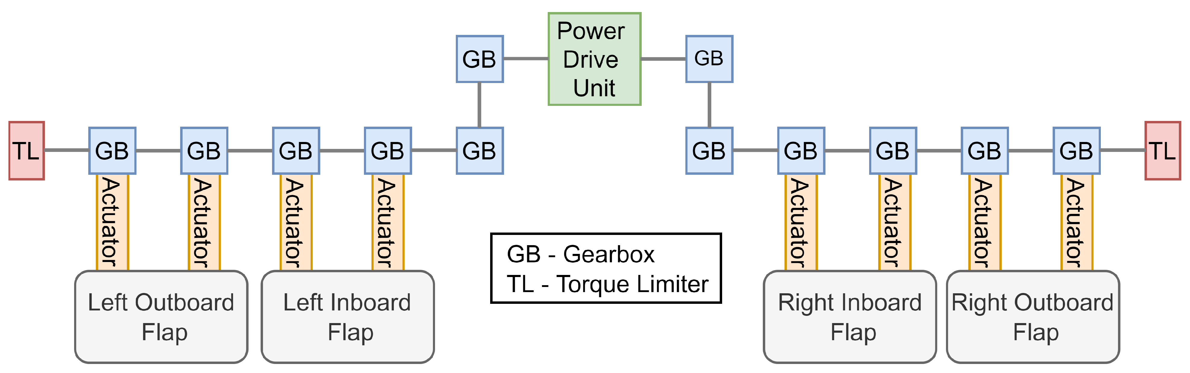
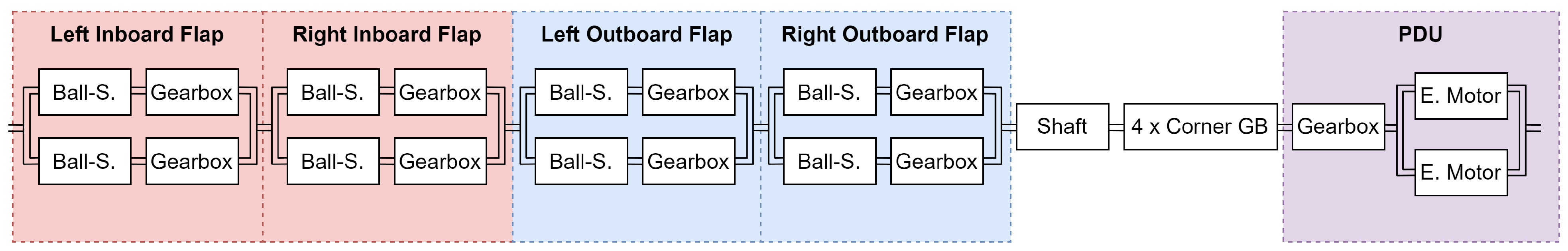
  • Conventional aircraft with conventional high-lift devices: The primary control surfaces are actuated by classic hydraulic linear actuators; the flaps and slats are mechanically actuated by a central power drive unit (Figure 1) that is powered by hydraulic motors;
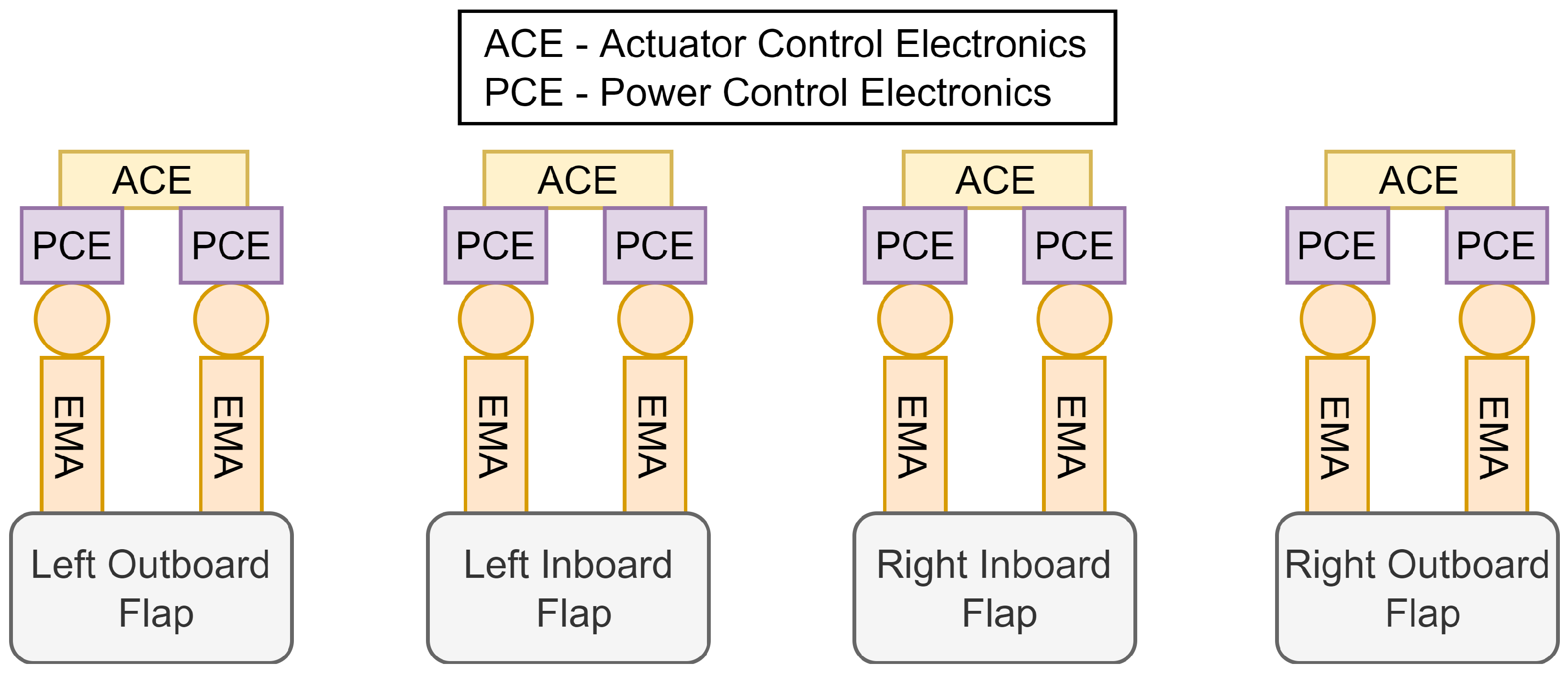
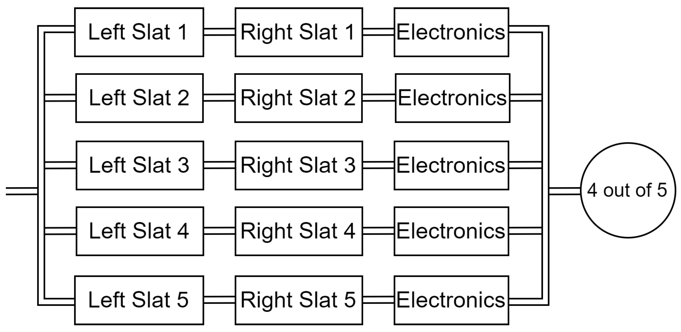
  • Conventional aircraft with innovative high-lift devices: The primary control surfaces are actuated by classic hydraulic linear actuators; the flaps and slats are actuated by EMAs (Figure 2);
  • All-electric aircraft with conventional high-lift devices: The primary control surfaces are actuated by electro-hydrostatic actuators (EHAs); the flaps and slats are mechanically actuated by a central power drive unit (Figure 1) that is powered by electric motors since there is no hydraulic system anymore;
  • All-electric aircraft with conventional high-lift devices: The primary control surfaces are actuated by electro-hydrostatic actuators (EHAs); the flaps and slats are actuated by EMAs (Figure 2).
The dedicated FCS tool reaches component level, and results are displayed in Table 3. It can be seen how the weight of the primary surfaces increases since EHAs are heavier than conventional hydraulic actuators. This comes from the fact that both rely on the same principle, but the EHAs have their own small hydraulic circuit and, hence, a higher weight. The innovative high-lift devices are lighter since the central mechanical components are nonexistent now. Also, the mechanical inefficiencies are not present anymore. The EMAs can be seen as a conjunct of a ballscrew actuator, a gearbox and an electric motor. The EMAs are sized specifically for each actuator station. This does not happen in the case with central mechanical shaft since the gearboxes need to be sized for the maximum torque of the shaft. This slight inefficiency makes the EMA design more optimal, saving also a part of the weight from this effect. As a result, it can be seen how the EMA architectures are lighter than the conventional ones.
The FCS results calculated by ASTRID are then substituted by the ones shown in Table 3. This results in four different files with different OBS mass, power off-takes and bleeding. The analysis does not end here; these on-board systems must be installed inside the aircraft to fully catch the effect of the mass, power and bleed differences among the architectures. For this, OpenAD is used again. In this case, the values obtained from ASTRID and the FCS sizing tool are fixed for OpenAD, forcing it to re-size the baseline aircraft maintaining those given values. Results are shown in Table 4. The first three rows are calculated following the method explained in Section 2.1.3. These results concern only the flight control system and are summed to the other OBS contributions. The middle rows are calculated with ASTRID, explained in Section 2.1.2. The total OBS mass is calculated as the one from ASTRID minus the FCS mass estimation from ASTRID plus the FCS mass from the dedicated tool (shown in row 1). The same process is repeated for the off-takes (called “Systems Power” in the table). Bleed values are directly taken from ASTRID without any change since the FCS does not affect this parameter. Ultimately, these values are given to OpenAD as fixed variables to estimate the MTOM and fuel burn, as shown in the last two rows. They are calculated following the method explained in Section 2.1.1. The general results from the table are now mentioned. It is noticeable how the third architecture has a higher FCS mass than the first one even if the overall effect is that the third aircraft is lighter. This comes from the effect that all the on-board systems have as a whole. Another interesting effect is that the difference in OBS mass does not translate directly to difference in maximum take-off mass. As an example, architectures 1 and 3 are compared. Architecture 1 weighs 846 kg, while architecture 3 weighs 1008 kg. When installed in their respective aircraft, the overall OBS mass of architecture 3 is 842 kg lighter than the one of architecture 1. However, the difference in MTOM is 1544 kg. This is known as the snowball effect. The savings in mass in the on-board systems translate into bigger savings in the total mass. This comes from the effect of needing to increase (or decrease) the weight of the structure and fuel accordingly. Also, the effect of the power off-takes and bleeding make the engine more efficient, since there are no losses; this reduces slightly the amount of fuel needed. Both effects combined make both all-electric architectures noticeably lighter than the conventional ones.
A detailed explanation of each result from Table 4 is provided here. The FCS mass varies among architectures. These detailed results can be checked in Table 3. The maximum power required by the flaps and slats is estimated following the methodology explained in Section 2.1.3. The first architecture requires no electric power off-take since the PDU is hydraulic, resulting in a value equal to zero for this reason. The architectures of aircraft 2 and 4 require the same power since they use the same high-lift devices concept. The sum among all the individual power from each EMA provides the total amount of power required by the systems. The architecture of aircraft 3 has an electric PDU, the power requirement of which is the total of the system (i.e., flaps and slats). This architecture requires a higher power demand than the other two more-electric ones. This is a direct cause of the mechanical inefficiencies caused by all the extra gearboxes and shafts. Some components need to be oversized to be able to bear the shaft torque. All the components of the mechanical chain are connected in series, which causes their respective inefficiencies to be multiplied. All these effects combined make this architecture less efficient in terms of power than the innovative one based on EMAs. With respect to the OBS mass, results are aligned with the ones from the two previous tables. It is calculated as the correspondent OBS mass calculated with ASTRID, subtracting the values for the FCS and updating them with the ones that come from the dedicated FCS tool. Bleed air is needed mainly for the environmental control system and ice protection. These systems require an engine bleed for the conventional OBS architectures. The values provided are directly estimated with ASTRID. Aircrafts 3 and 4 are based on all-electric architectures without a pneumatic system in which the environmental controls receive the required air from two external compressors, and the ice protection system is based on electric resistances. Engine bleed is not needed, and, consequently, it is equal to zero. Power off-takes are also calculated with ASTRID. It is noteworthy that both all-electric aircraft require a higher power demand since more systems are electrified. This value changes in take-off and climb since high-lift devices are used during these phases of the mission profile. It is constant between aircrafts 1 and 2 and aircrafts 3 and 4 because high-lift devices do not impact cruise off-takes. A higher power off-take can penalize fuel consumption since this translates into a higher power extraction from the engine. However, not needing to bleed air from the engines favors fuel consumption, allowing the engine to be more efficient [11]. The combination of both effects directly affects fuel consumption, and it is considered in this analysis. The last two values of the table (i.e., MTOM and fuel burn) are estimated with OpenAD and are sensitive to all the variables above. The combination of all the previous effects is taken into account in the final results. The heaviest aircraft corresponds to the conventional architecture with hydraulic PDU. This aircraft needs a hydraulic and pneumatic system, which translates into an elevated OBS mass and bleed penalty. A heavier aircraft generally results in a higher fuel demand. The combination of all the effects results in this aircraft having the highest fuel burn among all. On the other hand, the AEA with EMAs possesses the lightest OBS among all architectures, mainly because of the lack of hydraulic and pneumatic systems. It does not require a bleed from the engines, but it extracts the highest power off-take. The sum of these effects altogether results in the lowest specific fuel consumption among all aircraft, which results in the lowest MTOM as well. Aircrafts 2 and 3 represent intermediate points between aircrafts 1 and 2.
For validation purposes, the results obtained for the FCS mass are compared with the ones provided by the references. It is noticeable how the value for the conventional architecture (846 kg) differs from the one calculated in [5] (756 kg). This result is actually expected and explained. In [5], the exact hinge moments and forces for the A320 are used, which are extracted from different sources. In that paper, it is stated that hinge forces from Airbus and Boeing models differ significantly owing to structural and geometric reasons (e.g., slightly different chord ratios). An average between both is suggested in order not to bias the result towards one or the other, but, for the final results, the specific values for the Airbus model are used. Boeing models have higher forces and moments. As a result, using Airbus values leads to a lower FCS mass, using Boeing values leads to higher mass. Since the scope of this analysis is not to estimate the hinge models, the proposed surrogate model for hinge model estimation from [5] is used. This allows the subsystem from only some TLARs to be sized without needing to provide specific values for the hinge moments. This results in a slight overestimation of the hinge moments and forces, giving a higher value of the FCS mass, which fully explains the difference in results.

3.2. Reliability

The safety of the system can be represented at this level by the probability of failure. A direct comparison between the architectures (Figure 1 and Figure 2) can provide a proper initial estimation of their difference in terms of reliability. The reliability block diagram technique is used for this purpose. The first step is an estimation of the failure rates for each component. The Quanterion Automated Databook (NPRD-2016) is used since it contains real data about the failure rates of several components used in the aerospace sector. Even though most of the components are military, it provides a proper estimation of data that would not be possible to estimate otherwise since failure rates are, in general, sensitive data that companies do not share with the public. As a result, very little information can be gathered. Table 5 shows the values that are used for this analysis. In this table, the reader can find the exact name of the components as they are written in the database. The PDU is estimated as one single component modeled as two electric motors in parallel that are then connected in series to a gearbox, as suggested in [6].
Each component’s reliability can now be estimated following Equation (1). These values, however, are just estimations based on the data from the database and should not be considered as exact values for any component in general. Failure rates can vary heavily from one analysis to another even when comparing the same component. However, this can provide a proper comparison among different solutions, and the order of magnitude is much more significant than the value itself.
The first step to estimate the reliability is to create the RBD of the conventional high-lift device architecture. Following the guidelines from the standards [23], the correspondent diagram is created and shown in Figure 4, representing the RBD for the conventional flaps. Slats have an analogous diagram changing the number of surfaces from two to five and the number of corner gearboxes from four to two due to the wing geometry. The diagram shows the main shaft and the corner gearboxes as components without redundancy (i.e., without any component in parallel with them). This creates one of the main issues with this architecture; if the shaft breaks, the whole system is lost. This does not mean that a catastrophic failure happens since the torque limiters can block the shaft in position and the aircraft can perform the landing, but this affects the operational reliability since it is likely that the mission will be affected. Not fully deploying the high-lift devices requires a longer run that expected to perform the landing, which can cause the aircraft to abort the maneuver and try to land in another bigger airport. As stated in [18], transmission shaft fracture is one of the main issues in conventional high-lift devices. The actuators, however, are all redundant; two are present per each flap surface.
The RBD in Figure 4 with the corresponding failure rates provides a value of probability of failure for the conventional architecture of 1.2 × 10 6 . The innovative architecture from Figure 2 can be represented the same way. For this case, the PDU, gearboxes and shaft are not present so the RBD contains only EMAs in parallel and electronics in series. With this configuration, the results for the innovative architecture for flaps has a probability of failure of 5.6 × 10 6 , which is higher than the conventional one. This comparison should not be taken as exact since the results are hugely dependant in this case on the failure rates of the shaft and electronic components. Slight variations on these estimations massively affect the results. The main outcome is that both architectures have the same order of magnitude, and the one that performs best is determined by the failure rates (and hence the quality) of the components involved. This result is not the main outcome of this analysis. As explained before, the main advantage of the innovative architecture relies on the increase in operational reliability. This comes from the idea that removing the main shaft and mechanically disconnecting the surfaces allows them to be independently deployed [3]. This results in a completely different reliability block diagram in which the inboard and outboard flaps are in parallel and not in series as for the conventional case. The new RBD for the innovative architecture is shown in Figure 5. In can be noticed that two RBDs are obtained. One represents the case in which the actuator never suffers jamming, the other shows the case in which the actuator jams every time it suffers a failure. Both cases are extreme and not real for current EMAs, but knowing both sides gives some insights into the potential of the architecture.
The increase in operational reliability is seen directly in the RBDs since the inboard and outboard flaps go from a series to a parallel configuration. Deploying only one of them fulfills the mission. Slats work the same way but have a larger number of surfaces. As said before, the reference aircraft has two flap surfaces and five slat surfaces per wing. For the conventional case, all five slats are in series in an analogous RBD as shown in Figure 4. The main difference is that there are five surfaces instead of two. When switching to an innovative architecture, a question arises. This issue regards the amount of slat surfaces that need to be successfully deployed in order to consider the mission as fulfilled. For this case, in order to stay conservative, only one slat surface is allowed to fail, hence, fulfilling the mission if four out of five slats are deployed. The resulting RBD is shown in Figure 6.
It can be observed that an “m out of n” configuration is used for the reliability block diagram [23]. In this case, if there is no jamming, each of the slat surfaces is compound by two EMAs in parallel. In the case that an actuator failure always leads to a jamming, each surface is built as two EMAs in series, exactly as in the case for the flaps. All the necessary RBDs are now built. Results can be obtained and are shown in Table 6. Each case is solved with the correspondent reliability block diagram. All the cases for the innovative architecture with EMAs are calculated for the case in which the operational reliability is increased by allowing one surface to fail.
It is noticeable how massively the reliability increases when changing to EMAs. This comes from the effect of having the surfaces in parallel, whereas they are in series for the conventional case. Allowing one surface to fail highly increases reliability since the mission can be achieved even if one flap or slat surface fails, which is not the case for the conventional architecture. It is also interesting to see that reliability increases with respect to the conventional architecture even if the actuators suffer jamming. However, it is important to highlight that these architectures are based on the case in which the mission can be fulfilled with only one pair of flaps functioning. As commented before, the wing must be designed considering this feature, and not every aircraft could benefit from this high-lift device concept. As a final conclusion, the innovative architecture allows reliability to be highly increased. This mainly comes from the effect of eliminating the mechanical connection among surfaces, which allows the mission to still be fulfilled if one of the flap or slat surfaces fails.

4. Conclusions

This manuscript proposes a new methodology that allows quantitative results in terms of performance and reliability to be obtained for a new innovative concept of high-lift devices. This allows comparison of the results for such a new concept with the state-of-the-art architecture and better understanding of its benefits and potential. The reliability block diagram technique is used to estimate the probability of failure of the conventional and innovative architectures, providing the corresponding RBDs for each of them. A framework is provided to evaluate the performance aspects, summarized as aircraft MTOM and fuel burn. The framework consists of different steps starting with an aircraft baseline definition followed by the OBS sizing, FCS sizing and, eventually, aircraft synthesis. This framework allows all the effects of the new OBS that are installed in the aircraft to be fully captured.
Results show that the new architecture based on EMAs has strong potential in terms of reliability. This comes from the fact that this new concept allows mechanical connections among the actuators to be eliminated and, hence, deploys each surface independently from the others. All flap and slat surfaces are connected in series for the state-of-the-art architecture. However, the new concept allows them to be separated in parallel. This allows the mission to be fulfilled even if one surface fails. This effect might hugely increase the operational reliability. Jamming is still a failure mode that needs to be fully analyzed before introducing EMAs for this function, but there are several studies moving in the direction of free-jamming EMAs and into anti-jamming techniques. Nevertheless, the new architecture might benefit even if jamming is not fully eliminated (summary of results in Table 6).
In terms of performance, the innovative high-lift device concept brings promising results. Changing from a conventional to an all-electric architecture using the innovative high-lift devices entails an almost 4% reduction in maximum take-off mass for an A320neo-like aircraft, with a consequent reduction in fuel burn. This effect is produced by several factors such as the on-board systems being lighter and more efficient. Focusing strictly on the differences between both high-lift devices concepts, some conclusions are achieved. Removing the mechanical shaft allows mechanical inefficiencies that tend to oversize the actuators and gearboxes, as well as the main power drive unit, to be achieved. In the conventional architecture, the gearboxes are sized for the accumulated torque in the mechanical line, and this is far from optimal. Also, the central PDU is oversized to overcome the mechanical inefficiencies of the shaft and gearboxes. In the innovative case, each individual electric motor is more optimal since they are sized only for their corresponding actuator. The extra weight is then removed, as well as the torque limiters and the shaft. The extra power is removed as well since it is a more efficient architecture overall. Only the electronic devices are added, which are not heavy. The result is a noticeable reduction in weight (summary of results in Table 4).
As a main conclusion, it can be stated that the new high-lift device architecture proposed in literature and represented in Figure 2 has promising potential and could bring advantages in terms of performance and reliability when compared to the state-of-the-art flaps and slats. These results have a low technology readiness level (TRL) but establish a methodological base for further higher-fidelity studies. They also provide initial quantifiable estimations of the benefits that the new high-lift devices could bring in the future. Reliability results could be improved with more refined estimations of the failure rates of the components. This is currently a big gap in research since this type of data is not publicly available. The only accessible data usually come from old or outdated databases. This decreases the fidelity of the results, especially in the case of electric and electronic components. The estimation of performance characteristics can also be improved by using higher-fidelity tools for FCS, OBS and aircraft sizing. Also, having real data for the mass of the different actuators would provide a better comparison among architectures. Nevertheless, the suggested methodology successfully provides the guidelines and framework to further study the proposed innovative high-lift device architecture, and the results continue to support the necessity for further research on EMAs and jamming.

Author Contributions

Conceptualization, C.C.d.l.H.; methodology, C.C.d.l.H.; validation, C.C.d.l.H.; formal analysis, C.C.d.l.H. and M.F.; investigation, C.C.d.l.H. and M.F.; resources, C.C.d.l.H.; data curation, C.C.d.l.H.; writing—original draft preparation, C.C.d.l.H.; writing—review and editing, C.C.d.l.H., M.F. and L.B.; visualization, C.C.d.l.H.; supervision, C.C.d.l.H., M.F. and L.B.; project administration, C.C.d.l.H.; funding acquisition, C.C.d.l.H. and L.B. All authors have read and agreed to the published version of the manuscript.

Funding

This research received no external funding.

Data Availability Statement

No new data or datasets were created further than the one already presented in the manuscript.

Conflicts of Interest

The authors declare no conflicts of interest. The funders had no role in the design of the study; in the collection, analyses, or interpretation of data; in the writing of the manuscript; or in the decision to publish the results.

Abbreviations

The following abbreviations are used in this manuscript:
λ Failure rates
ACEActuator control electronics
EHAElectro-hydrostatic actuator
EMAElectromechanical actuator
FCSFlight control system
GBGearbox
MTOMMaximum take-off mass
OBSOn-board systems
PCEPower control electronics
PDUPower drive unit
RBDReliability block diagram
TLTorque limiter
TLARsTop-level aircraft requirements

References

  1. Moir, I.; Seabridge, A. Aircraft Systems: Mechanical, Electrical, and Avionics Subsystems Integration; John Wiley & Sons: New York, NY, USA, 2011; Volume 52. [Google Scholar]
  2. Cabaleiro De La Hoz, C. Environmental Control System and Flight Control System Architecture Optimization from a Family Concept Design Perspective. Master’s Thesis, Politecnico di Torino, Torino, Italy, 2020. [Google Scholar]
  3. Recksiek, M. Advanced high lift system architecture with distributed electrical flap actuation. In Proceedings of the 2nd International Workshop on Aircraft System Technologies, Hamburg, Germany, 26–27 March 2009; Shaker Verlag: Aachen, Germany, 2009; pp. 49–59. [Google Scholar]
  4. Janker, P.; Claeyssen, F.; Grohmann, B.; Christmann, M.; Lorkowski, T.; LeLetty, R.; Sosniki, O.; Pages, A. New actuators for aircraft and space applications. In Proceedings of the 11th International Conference on New Actuators, Bremen, Germany, 9–11 June 2008; pp. 9–11. [Google Scholar]
  5. Cabaleiro de la Hoz, C.; Fioriti, M. New methodology for flight control system sizing and hinge moment estimation. Proc. Inst. Mech. Eng. Part G J. Aerosp. Eng. 2022, 236, 2375–2390. [Google Scholar] [CrossRef]
  6. Benarous, M.; Panella, I. Flap system power drive unit (PDU) architecture optimisation. J. Eng. 2019, 17, 3500–3504. [Google Scholar] [CrossRef]
  7. Belmonte, D.; Dalla Vedova, M.D.L.; Quattrocchi, G. A new active asymmetry monitoring and control technique applied to critical aircraft flap control system failures. MATEC Web Conf. EDP Sci. 2019, 304, 04011. [Google Scholar] [CrossRef]
  8. Lin, T.; Pecora, R.; Ciliberti, D.; Xia, W.; Hu, S. Aerodynamic optimization of an adaptive flap for next-generation green aircraft. Chin. J. Aeronaut. 2024, 37, 100–122. [Google Scholar] [CrossRef]
  9. Mazzoleni, M.; Di Rito, G.; Previdi, F. Electro-Mechanical Actuators for the More Electric Aircraft; Springer: Cham, Switzerland, 2021. [Google Scholar]
  10. Castellini, L.; D’Andrea, M.; Borgarelli, N. Analysis and design of a linear electro-mechanical actuator for a high lift system. In Proceedings of the International Symposium on Power Electronics, Electrical Drives, Automation and Motion, Ischia, Italy, 18–20 June 2014; IEEE: Paolo Alto, CA, USA, 2014; pp. 243–247. [Google Scholar]
  11. Fioriti, M.; Della Vecchia, P.; Donelli, G. Effect of Progressive Integration of On-Board Systems Design Discipline in an MDA Framework for Aircraft Design with Different Level of Systems Electrification. Aerospace 2022, 9, 161. [Google Scholar] [CrossRef]
  12. Derrien, J.C.; Sécurité, S.D. Electromechanical actuator (EMA) advanced technologies for flight controls. In Proceedings of the International Congress of the Aeronautical Sciences, Brisbane, Australia, 23–28 September 2012; pp. 1–10. [Google Scholar]
  13. Li, J.; Yu, Z.; Huang, Y.; Li, Z. A review of electromechanical actuation system for more electric aircraft. In Proceedings of the IEEE International Conference on Aircraft Utility Systems (AUS), Beijing, China, 10–12 October 2016; IEEE: New York, NY, USA, 2016; pp. 490–497. [Google Scholar]
  14. Di Rito, G.; Luciano, B.; Borgarelli, N.; Nardeschi, M. Model-based condition-monitoring and jamming-tolerant control of an electro-mechanical flight actuator with differential ball screws. Actuators 2021, 10, 230. [Google Scholar] [CrossRef]
  15. Ciliberti, D.; Della Vecchia, P.; Memmolo, V.; Nicolosi, F.; Wortmann, G.; Ricci, F. The Enabling Technologies for a Quasi-Zero Emissions Commuter Aircraft. Aerospace 2022, 9, 319. [Google Scholar] [CrossRef]
  16. Qiao, G.; Liu, G.; Shi, Z.; Wang, Y.; Ma, S.; Lim, T.C. A review of electromechanical actuators for More/All Electric aircraft systems. Proc. Inst. Mech. Eng. Part C J. Mech. Eng. Sci. 2018, 232, 4128–4151. [Google Scholar] [CrossRef]
  17. Mazzoleni, M.; Previdi, F.; Scandella, M.; Pispola, G. Experimental development of a health monitoring method for electro-mechanical actuators of flight control primary surfaces in more electric aircraft. IEEE Access 2019, 7, 153618–153634. [Google Scholar] [CrossRef]
  18. Pang, H.; Yu, T.; Song, B. Failure mechanism analysis and reliability assessment of an aircraft slat. Eng. Fail. Anal. 2016, 60, 261–279. [Google Scholar] [CrossRef]
  19. Hussain, Y.M.; Burrow, S.; Henson, L.; Keogh, P. A review of techniques to mitigate jamming in electromechanical actuators for safety critical applications. Int. J. Progn. Health Manag. 2018, 9, 3. [Google Scholar] [CrossRef]
  20. Garcia, A.; Cusido, I.; Rosero, J.A.; Ortega, J.A.; Romeral, L. Reliable electro-mechanical actuators in aircraft. IEEE Aerosp. Electron. Syst. Mag. 2008, 23, 19–25. [Google Scholar] [CrossRef]
  21. Mazzoleni, M.; Maccarana, Y.; Previdi, F.; Pispola, G.; Nardi, M.; Perni, F.; Toro, S. Development of a reliable electro-mechanical actuator for primary control surfaces in small aircrafts. In Proceedings of the 2017 IEEE International Conference on Advanced Intelligent Mechatronics (AIM), Munich, Germany, 3–7 July 2017; IEEE: New York, NY, USA, 2017; pp. 1142–1147. [Google Scholar]
  22. Cabaleiro, C.; Fioriti, M.; Boggero, L. Methodology for the Automated Preliminary Certification of On-Board Systems Architectures through Requirements Analysis. In Proceedings of the 33rd Congress of the International Council of the Aeronautical Sciences, Stockholm, Sweden, 4–9 September 2022; pp. 4–9. [Google Scholar]
  23. IEC. 61078, Analysis Techniques for Dependability-Reliability Block Diagram and Boolean Methods; IEC: Geneva, Switzerland, 2006. [Google Scholar]
  24. Woehler, S.; Atanasov, G.; Silberhorn, D.; Fröhler, B.; Zill, T. Preliminary aircraft design within a multidisciplinary and multifidelity design environment. In Proceedings of the Aerospace Europe Conference, Bordeaux, France, 25–28 February 2020. [Google Scholar]
  25. Chiesa, S.; Di Meo, G.A.; Fioriti, M.; Medici, G.; Viola, N. ASTRID-aircraft on board systems sizing and trade-off analysis in initial design. In Proceedings of the 10th Research and Education in Aircraft Design Conference, READ, Brno, Czech Republic, 17–19 October 2012; Research Bulletin/Warsaw University of Technology, Institute of Aeronautics and Applied Mechanics. Volume 1, pp. 1–28, ISSN 1425-2104. [Google Scholar]
  26. Page Risueño, A.; Bussemaker, J.; Ciampa, P.D.; Nagel, B. MDAx: Agile generation of collaborative MDAO workflows for complex systems. In Proceedings of the AIAA Aviation 2020 Forum, Virtual, 15–19 June 2020; p. 3133. [Google Scholar]
  27. Boggero, L. Design Techniques to Support Aircraft Systems Development in a Collaborative MDO Environment. Ph.D. Thesis, Politecnico di Torino, Torino, Italy, 2018. [Google Scholar]
  28. Fioriti, M.; Di Fede, F. A Design Model for Electric Environmental Control System in Aircraft Conceptual and Preliminary Design. Int. Rev. Aerosp. Eng. 2023, 16, 58–72. [Google Scholar] [CrossRef]
  29. Bussemaker, J.H.; Ciampa, P.D.; Singh, J.; Fioriti, M.; Cabaleiro De La Hoz, C.; Wang, Z.; Peeters, D.; Hansmann, P.; Della Vecchia, P.; Mandorino, M. Collaborative design of a business jet family using the AGILE 4.0 MBSE environment. In Proceedings of the AIAA Aviation 2022 Forum, Chicago, IL, USA, 27 June–1 July 2022; p. 3934. [Google Scholar]
  30. Mandorino, M.; Della Vecchia, P.; Corcione, S.; Nicolosi, F.; Trifari, V.; Cerino, G.; Fioriti, M.; De La Hoz, C.C.; Lefebvre, T.; Charbonnier, D.; et al. Multidisciplinary design and optimization of regional jet retrofitting activity. In Proceedings of the AIAA Aviation 2022 Forum, Chicago, IL, USA, 27 June–1 July 2022; p. 3933. [Google Scholar]
  31. Chakraborty, I.; Mavris, D.N.; Emeneth, M.; Schneegans, A. A methodology for vehicle and mission level comparison of More Electric Aircraft subsystem solutions: Application to the flight control actuation system. Proc. Inst. Mech. Eng. Part G J. Aerosp. Eng. 2015, 229, 1088–1102. [Google Scholar] [CrossRef]
  32. Vladimirov, S.; Forde, S. Demonstration program to design, manufacture and test an autonomous electro-hydrostatic actuator to gimbal large booster-class engines. In Proceedings of the 42nd AIAA/ASME/SAE/ASEE Joint Propulsion Conference and Exhibit, Sacramento, CA, USA, 9–12 July 2006; p. 4364. [Google Scholar]
  33. Cabaleiro, C.; Fioriti, M.; Boggero, L. Automated generation of aircraft on-board system architectures and filtering through certification specification requirements. In Proceedings of the 13th EASN International Conference in Innovation in Aviation, Salerno, Italy, 5–8 September 2023. [Google Scholar]
Figure 1. Scheme of the conventional flap architecture.
Aerospace 11 00468 g001
Figure 2. Scheme of the innovative more-electric flap architecture.
Aerospace 11 00468 g002
Figure 3. Extended design structure matrix representing the performance evaluation workflow, created with MDAX [26].
Aerospace 11 00468 g003
Figure 4. RBD of the conventional flap system.
Aerospace 11 00468 g004
Figure 5. RBD of the innovative flap system. (a) Case without jamming. (b) Case with jamming.
Aerospace 11 00468 g005
Figure 6. RBD of the innovative slat system.
Aerospace 11 00468 g006
Table 1. Main characteristics of the A320neo baseline.
ParameterUnitsValueParameterUnitsValue
Max. Take-Off Masskg78,981Engine Model-PW1133
Fuselage Lengthm37.57Static Thrust (ISA)kN147.3
Wing Aream2124.78Seats-180
Wing Spanm35.8Design Cruise Mach-0.78
Vertical Tail Aream222.49Design Rangenm2935
Max. Lift Coefficient, Landing-2.9Max. Lift Coefficient, Take-Off-2.55
Table 2. ASTRID results for both OBS architectures.
Conventional [kg]All Electric [kg]Variation [%]
Avionics7817810
Flight Control System878737−16
Ice Protection System73764.4
Environmental Control System48058922.6
Fuel System3443440
Landing Gear217623206.6
Fire Protection95950
Lights3413410
Oxygen1121120
Water Waste3023020
APU138122−11.7
Pneumatic System1600−100
Hydraulic System10220−100
Electrical System14431366−5.3
Total83447184−13.9
Table 3. Results in terms of mass of the four high-lift device architectures.
Conventional Aircraft
with Hydraulic PDU
Conventional Aircraft
with EMAs
All-Electric Aircraft
with Electric PDU
All-Electric Aircraft
with EMAs
ComponentNumber of
Instances
Mass of One
Instance [kg]
Number of
Instances
Mass of One
Instance [kg]
Number of
Instances
Mass of One
Instance [kg]
Number of
Instances
Mass of One
Instance [kg]
Aileron actuator418.75418.75429.40429.40
Elevator actuator417.91417.91428.05428.05
Rudder actuator311.26311.26318.01318.01
Spoiler actuator109.66109.661015.451015.45
Total *, Primary Surfaces-276.96-276.96-438.33-438.33
Flap actuator813.28823.24813.28823.24
Flap gearbox812.2400812.2400
Flap corner gearbox413.4000413.4000
Flap torque limiter25.510025.5100
Flap PDU155.1400155.1400
Flap shafts14.300014.3000
Flap electronics00118.5900118.59
Total *, Flaps-328.21-204.48-328.21-204.48
Slat actuator203.36206.53203.36206.53
Slat gearbox206.2100206.2100
Slat corner gearbox26.760026.7600
Slat torque limiter22.800022.8000
Slat PDU127.8100127.8100
Slat shafts12.730012.7300
Slat electronics00113.0600113.06
Total *, Slats-241.17-143.69-241.17-143.69
Total *, Flight Control System-846.34-625.13-1007.71-786.50
* Rows in italic show the sum of the components inside the corresponding component group, delimited by horizontal lines. Last row in bold shows the total sum of all the components.
Table 4. Results in terms of MTOM and fuel burn of the four high-lift device architectures.
Conventional Aircraft
with Hydraulic PDU (1) *
Conventional Aircraft
with EMAs (2) *
All-Electric Aircraft
with Electric PDU (3) *
All-Electric Aircraft
with EMAs (4) *
FCS Mass [kg]846.34625.131007.71786.50
Flaps Power Max [kW]02.9085.9402.908
Slats Power Max [kW]01.8332.9951.833
OBS Mass [kg]8312809174557234
Bleed, Cruise [kg/s]0.880.8800
Bleed, Climb [kg/s]1.431.4300
Systems Power, Cruise [kW]218218387387
Systems Power, Climb [kW]170175245241
Systems Power, Take-Off [kW]5964147143
MTOM [kg]78,96678,62577,42277,080
Fuel Burn [kg]19,07918,92118,48818,332
* First three rows are calculated with the dedicated FCS sizing tool. Middle rows are calculated with ASTRID and updated with the previous values. Last rows are calculated with OpenAD after receiving the feedback from the values above. It should be noted that these results are generated based on real actuators that suffer jamming.
Table 5. Failure rates values for high-lift devices components.
ComponentName in DatabaseFailure Rates (per Hour) *
Ballscrew ActuatorBallscrew Assembly1.274 × 10−5
EMA ActuatorActuator Electromechanical Linear2.335 × 10−5
GearboxGearbox Assembly2.35 × 10−7
Corner GearboxGearbox Assembly2.35 × 10−7
ShaftShaft Assembly, Flap Drive Torque5.81 × 10−8
Electric MotorMotor AC2.39 × 10−6
Electronic DevicesComputer Flight Control2.79 × 10−6
* Values obtained from the Quanterion Automated Databook (NPRD-2016).
Table 6. Reliability results for the different high-lift device architectures.
ArchitectureConventional with
Central Mechanical
Shaft and PDU
Innovative with EMAs
(Case without Jamming)
Innovative with EMAs
(Extreme Case in Which Every
Actuator Failure Causes Jamming)
Flap Probability of Failure, per hour1.2 × 10−6 *7.8 × 10−12 †9.2 × 10⁻⁹ §
Slat Probability of Failure, per hour7.6 × 10−7 *7.8 × 10−11 ¶9.2 × 10⁻⁸ ¶
* Estimated following the RBD in Figure 4. Estimated following the RBD in Figure 5a. § Estimated following the RBD in Figure 5b. Estimated following the RBD in Figure 6.
Disclaimer/Publisher’s Note: The statements, opinions and data contained in all publications are solely those of the individual author(s) and contributor(s) and not of MDPI and/or the editor(s). MDPI and/or the editor(s) disclaim responsibility for any injury to people or property resulting from any ideas, methods, instructions or products referred to in the content.

