
Research on the Heat Dissipation in Aviation-Integrated Communication Equipment Based on Graphene Films


Abstract
1. Introduction
2. Three-Dimensional Modeling of Aviation-Integrated Communication Equipment
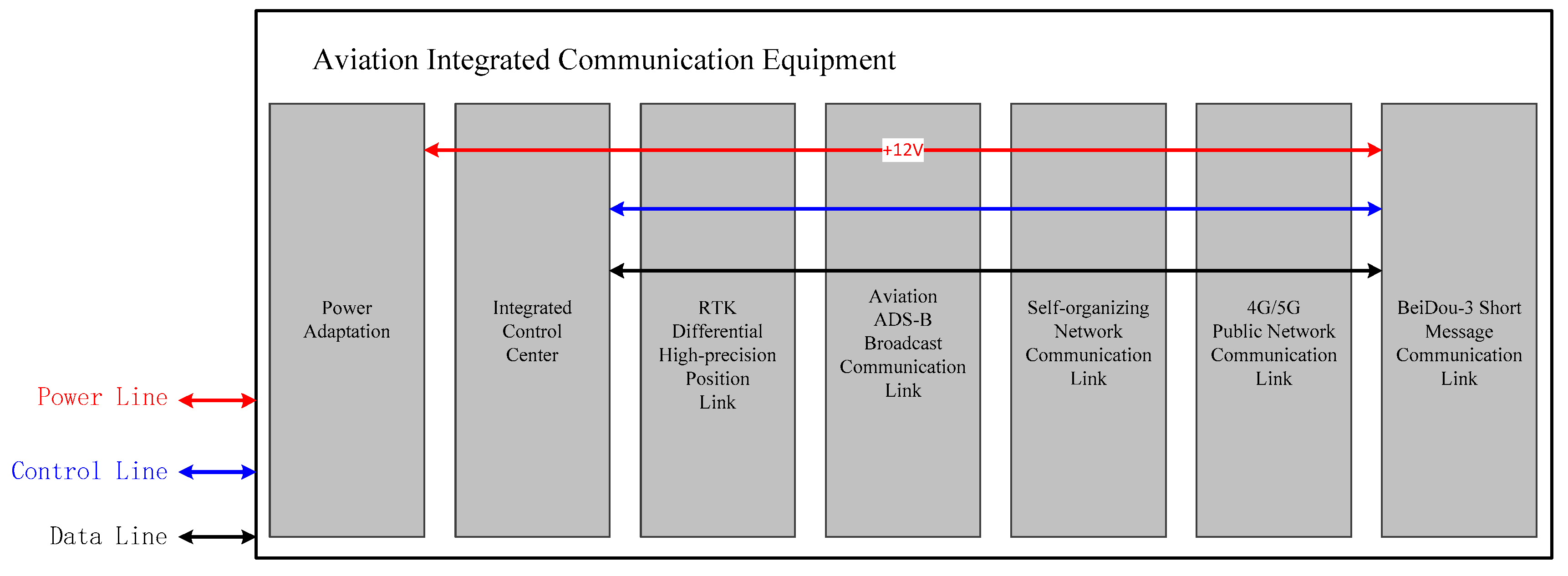
2.1. Equipment Composition
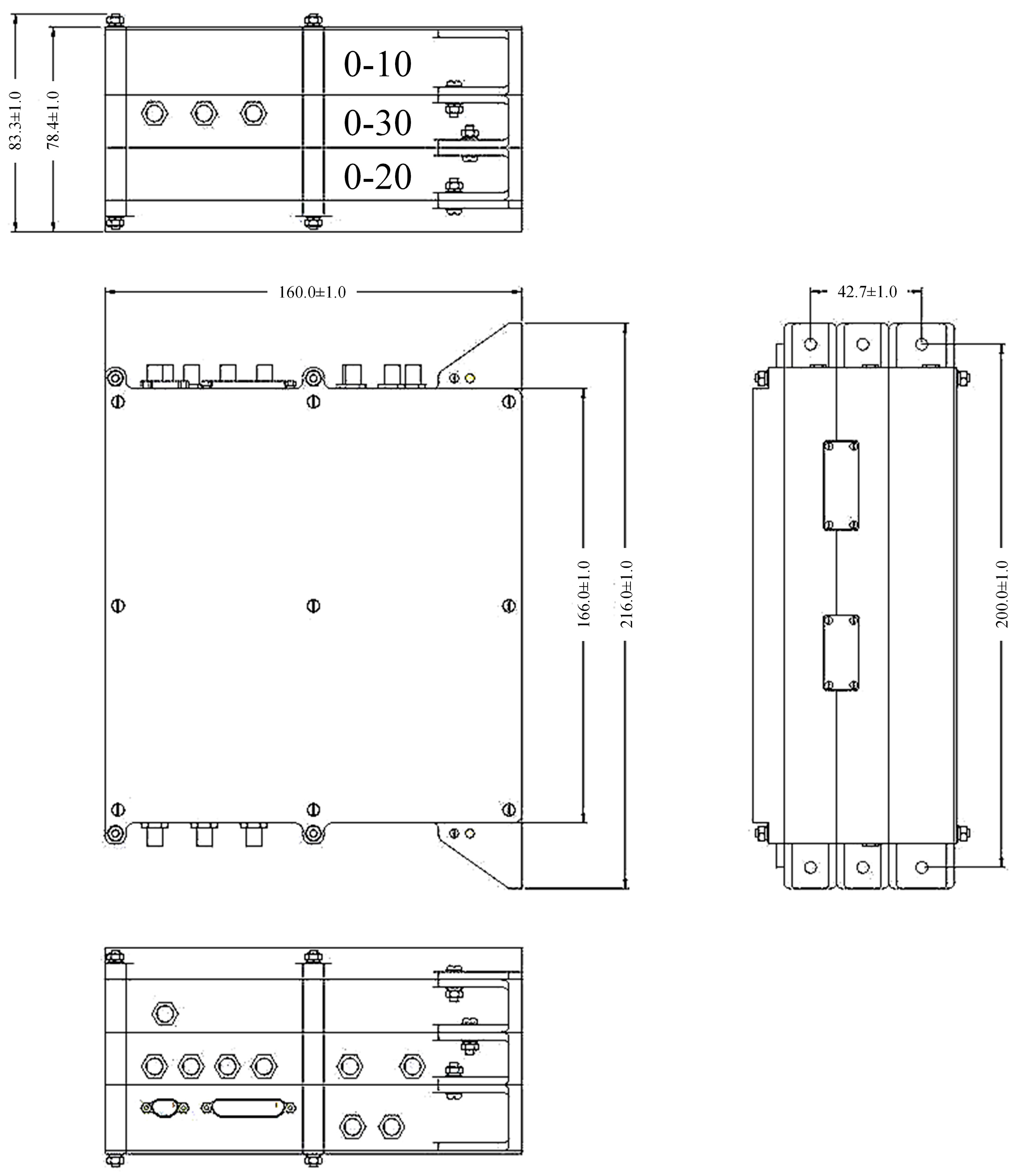
2.2. Mechanical Property
- ①
- Shape size: (216.0 ± 1.0) mm × (160.0 ± 1.0) mm × (83.3 ± 1.0) mm;
- ②
- Equipment power dissipation: 28 V/82.5 V (peak value), 41.5 W (mean value), power dissipation is shown in Table 1.
3. Mathematical Modeling
3.1. Model Condition
- ①
- Working mode: prolonged continuous running;
- ②
- Working situation: initial temperature 25 °C, working temperature range 25~40 °C;
- ③
- Installation mode: the terminal is installed in contact with the cabin flat, and temperature control of the installation surface is constant at 40 °C;
- ④
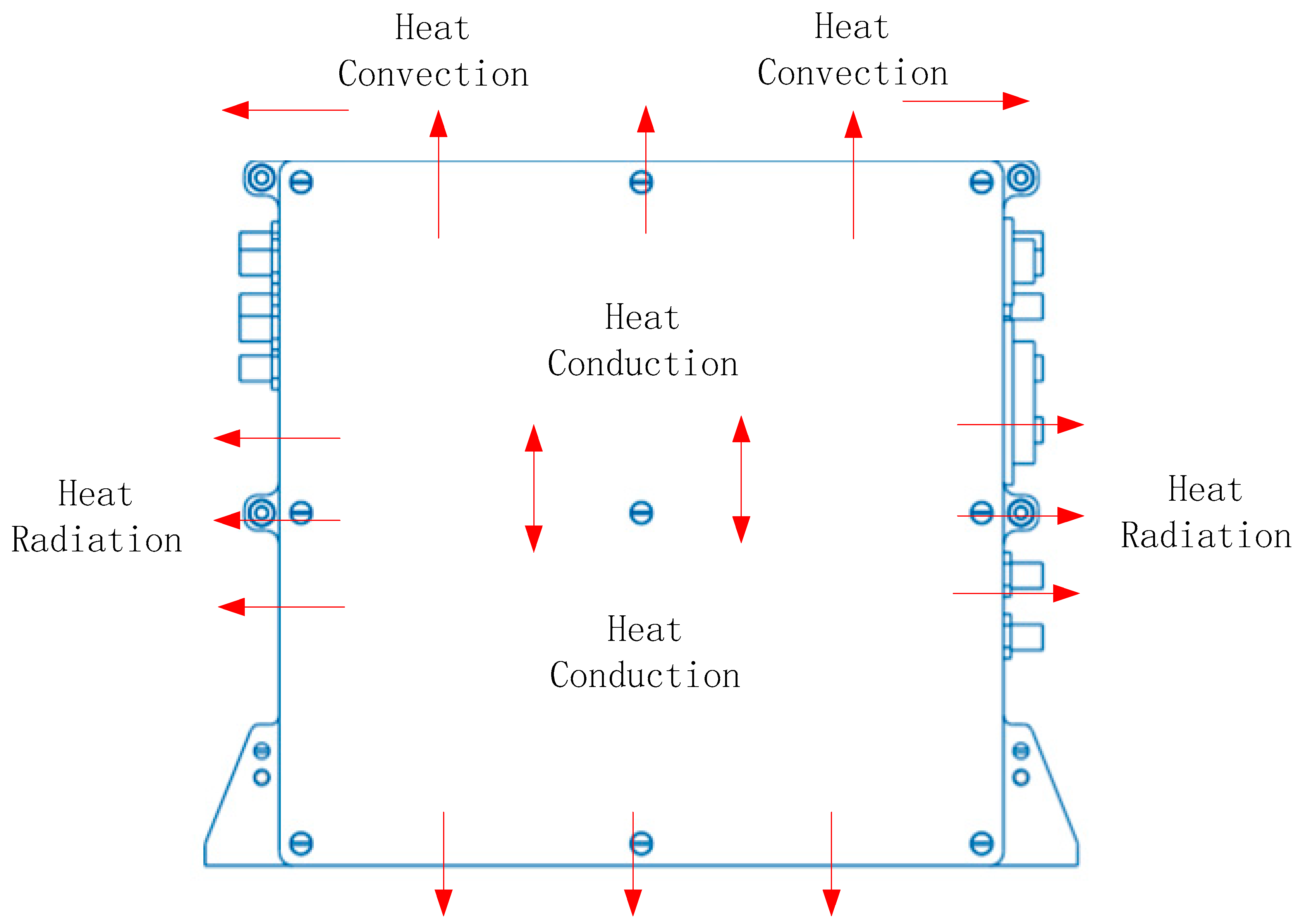
- Heat dissipation mode: convection heart dissipation mainly, radiation heat transfer auxiliary, as is shown in Figure 4;
- ⑤
- Surface operation: increasing heat dissipation with black anodization, heat radiation rates = 0.88;
- ⑥
- Working heat consumption: the average thermal power consumption of the equipment is 41.5 W.
3.2. Model Parameters
- (1)
- Aluminum alloy parameters
- (2)
- Graphene films on the surface of magnesium alloy parameters
- (3)
- Heat source parameters
3.3. Model Development
- (1)
- Rationale
- (2)
- Simulation Model
4. Results and Discussion
4.1. Aluminum Alloy Simulation Results and Discussion
4.2. Magnesium Alloy Simulation Results and Discussion
4.3. Graphene Films on the Surface of Magnesium Alloy Simulation Results and Discussion
5. Conclusions and Future Work
Author Contributions
Funding
Data Availability Statement
Acknowledgments
Conflicts of Interest
References
- Collinson, R.P.G. Introduction to Avionics Systems; Springer Nature: Berlin/Heidelberg, Germany, 2023. [Google Scholar]
- Todd, D.; Simpson, J. The World Aircraft Industry; Routledge: London, UK, 2019. [Google Scholar]
- Avionics: Development and Implementation; CRC Press: Boca Raton, FL, USA, 2018.
- Wang, Y.; Lei, H.; Hackett, R.; Beeby, M. Safety Assessment Process Optimization for Integrated Modular Avionics. IEEE Aerosp. Electron. Syst. Mag. 2019, 34, 58–67. [Google Scholar] [CrossRef]
- Yu, Q.Y.; Liu, H.; Xu, P.Z.; Li, J.X.; Zhang, L.; Chen, H.H. Next generation wireless avionics intra-communications: Challenges and research topics. IEEE Wirel. Commun. 2022, 30, 87–95. [Google Scholar] [CrossRef]
- Mäurer, N.; Guggemos, T.; Ewert, T.; Gräupl, T.; Schmitt, C.; Grundner-Culemann, S. Security in digital aeronautical communications a comprehensive gap analysis. Int. J. Crit. Infrastruct. Prot. 2022, 38, 100549. [Google Scholar] [CrossRef]
- Kokkoniemi, J.; Jornet, J.M.; Petrov, V.; Koucheryavy, Y.; Juntti, M. Channel modeling and performance analysis of airplane-satellite terahertz band communications. IEEE Trans. Veh. Technol. 2021, 70, 2047–2061. [Google Scholar] [CrossRef]
- Zolanvari, M.; Jain, R.; Salman, T. Potential data link candidates for civilian unmanned aircraft systems: A survey. IEEE Commun. Surv. Tutor. 2019, 22, 292–319. [Google Scholar] [CrossRef]
- Wang, G.; Zhao, W. The Principles of Integrated Technology in Avionics Systems; Academic Press: Cambridge, MA, USA, 2020. [Google Scholar]
- Avtin, I.V.; Baburov, V.I.; Ponomarenko, B.V.; Shatrakov, Y.G. Principles of Integrated Airborne Avionics; Springer: Singapore, 2021. [Google Scholar]
- Moysen, J.; Giupponi, L. From 4G to 5G: Self-organized network management meets machine learning. Comput. Commun. 2018, 129, 248–268. [Google Scholar] [CrossRef]
- Guimaraes, C.; Li, X.; Papagianni, C.; Mangues-Bafalluy, J.; Contreras, L.M.; Garcia-Saavedra, A.; Brenes, J.; Cristobal, D.S.; Alonso, J.; Zabala, A.; et al. Public and non-public network integration for 5Growth industry 4.0 use cases. IEEE Commun. Mag. 2021, 59, 108–114. [Google Scholar] [CrossRef]
- Krasuski, K.; Ciećko, A.; Bakuła, M.; Grunwald, G.; Wierzbicki, D. New methodology of designation the precise aircraft position based on the RTK GPS solution. Sensors 2021, 22, 21. [Google Scholar] [CrossRef] [PubMed]
- Li, G.; Guo, S.; Lv, J.; Zhao, K.; He, Z. Introduction to global short message communication service of BeiDou-3 navigation satellite system. Adv. Space Res. 2021, 67, 1701–1708. [Google Scholar] [CrossRef]
- Zhang, X.; Zhang, J.; Wu, S.; Cheng, Q.; Zhu, R. Aircraft monitoring by the fusion of satellite and ground ADS-B data. Acta Astronaut. 2018, 143, 398–405. [Google Scholar] [CrossRef]
- Lv, Y.-G.; Zhang, G.-P.; Wang, Q.-W.; Chu, W.-X. Thermal Management Technologies Used for High Heat Flux Automobiles and Aircraft: A Review. Energies 2022, 15, 8316. [Google Scholar] [CrossRef]
- Li, J.; Cui, J.-C.; Yang, Z.-Z.; Qiu, H.-X.; Tang, Z.-H.; Yang, J.-H. Stabilizing graphene layers by intercalating laponite between them. New Carbon Mater. 2018, 33, 19–25. [Google Scholar] [CrossRef]
- Feng, C.P.; Bai, L.; Bao, R.Y.; Wang, S.W.; Liu, Z.; Yang, M.B.; Chen, J.; Yang, W. Superior thermal interface materials for thermal management. Compos. Commun. 2019, 12, 80–85. [Google Scholar] [CrossRef]
- Fan, D.; Jin, M.; Wang, J.; Liu, J.; Li, Q. Enhanced heat dissipation in graphite-silver-polyimide structure for electronic cooling. Appl. Therm. Eng. 2020, 168, 114676. [Google Scholar] [CrossRef]
- Li, W.; Wang, F.; Cheng, W.; Chen, X.; Zhao, Q. Study of using enhanced heat-transfer flexible phase change material film in thermal management of compact electronic device. Energy Convers. Manag. 2020, 210, 112680. [Google Scholar] [CrossRef]
- Li, H.-L.; Xiao, S.-N.; Yu, H.-L.; Xue, Y.-H.; Yang, J.-H. A review of graphene-based films for heat dissipation. New Carbon Mater. 2021, 36, 897–908. [Google Scholar] [CrossRef]
- Yang, D.; Yao, Q.; Jia, M.; Wang, J.; Zhang, L.; Xu, Y.; Qu, X. Application analysis of efficient heat dissipation of electronic equipment based on flexible nanocomposites. Energy Built Environ. 2020, 2, 157–166. [Google Scholar] [CrossRef]
- Chen, Y.; Zhang, H.; Chen, J.; Guo, Y.; Jiang, P.; Gao, F.; Bao, H.; Huang, X. Thermally conductive but electrically insulating polybenzazole nanofiber/boron nitride nanosheets nanocomposite paper for heat dissipation of 5G base stations and transformers. ACS Nano 2022, 16, 14323–14333. [Google Scholar] [CrossRef] [PubMed]
- Li, H.; Wu, X.; Cheng, K.; Zhu, M.H.; Wang, L.S.; Yu, H.L.; Yang, J.H. One-pot modified “grafting-welding” preparation of graphene/polyimide carbon films for su-perior thermal management. Carbon 2022, 186, 738. [Google Scholar] [CrossRef]
- Wang, S.; Wang, H.; Chang, M.; Xu, J.; Wang, J.; Yang, X.; Bai, J. A novel battery thermal management system for an unmanned aerial vehicle using the graphene directional heat transfer structure. J. Power Sources 2023, 588, 233726. [Google Scholar] [CrossRef]
- Yang, P.; Wu, B.; Tong, X.; Zeng, M.; Wang, Q.; Cheng, Z. Insight into heat transfer process of graphene aerogel composite phase change material. Energy 2023, 279, 128051. [Google Scholar] [CrossRef]
- Lim, Y.S.; Hung, Y.M. Nucleate boiling enhancement on hybrid graphene-nanoplatelets/carbon nanotubes coatings for light-emitting diode cooling. Appl. Therm. Eng. 2024, 2024, 122785. [Google Scholar] [CrossRef]
- Zhang, L.; Hou, G.; Zhai, W.; Ai, Q.; Feng, J.; Zhang, L.; Si, P.; Ci, L. Aluminum/graphene composites with enhanced heat-dissipation properties by in-situ re-duction of graphene oxide on aluminum particles. J. Alloys Compd. 2018, 748, 854–860. [Google Scholar] [CrossRef]
- Zhang, H.; Guo, B.; Zhao, X.; Chen, C. Microstructure and corrosion behavior of 2A12 aluminum alloys by high frequency im-pacting and rooling. CIRP J. Manuf. Sci. Technol. 2023, 41, 328–337. [Google Scholar] [CrossRef]
- Li, Y.T.; Liu, W.J.; Shen, F.X.; Zhang, G.D.; Gong, L.X.; Zhao, L.; Song, P.; Gao, J.-F.; Tang, L.C. Processing, thermal conductivity and flame retardant properties of silicone rubber filled with different geometries of thermally conductive fillers: A comparative study. Compos. Part B Eng. 2022, 238, 109907. [Google Scholar] [CrossRef]
- Yousef, S.; Subadra, S.P.; Griškevičius, P.; Varnagiris, S.; Milcius, D.; Makarevicius, V. Superhydrophilic functionalized graphene/fiberglass/epoxy laminates with high mechanical, impact and thermal performance and treated by plasma. Polym. Test. 2020, 90, 106701. [Google Scholar] [CrossRef]
- Anene, A.F.; Fredriksen, S.B.; Sætre, K.A.; Tokheim, L.-A. Experimental study of thermal and catalytic pyrolysis of plastic waste components. Sustainability 2018, 10, 3979. [Google Scholar] [CrossRef]
- Wu, D.; Cheng, F.; Yang, F.; He, W. Non-destructive testing of carbon-fiber-reinforced plastics with a PCB-based T-R probe. Compos. Struct. 2020, 240, 112080. [Google Scholar] [CrossRef]
- Li, S.; Yang, X.; Hou, J.; Du, W. A review on thermal conductivity of magnesium and its alloys. J. Magnes. Alloy. 2020, 8, 78–90. [Google Scholar] [CrossRef]
- Yang, Y.; Xiong, X.; Chen, J.; Peng, X.; Chen, D.; Pan, F. Research advances in magnesium and magnesium alloys worldwide in 2020. J. Magnes. Alloy. 2021, 9, 705–747. [Google Scholar] [CrossRef]
- Balandin, A.A.; Ghosh, S.; Bao, W.; Calizo, I.; Teweldebrhan, D.; Miao, F.; Lau, C.N. Superior thermal conductivity of single-layer graphene. Nano Lett. 2008, 8, 902–907. [Google Scholar] [CrossRef]


| Module | Static Power Dissipation (W) | Peak Value Power Dissipation (W) |
|---|---|---|
| Self-organizing network communication module | 2.0 | 5.0 |
| 4G/5G public network communication module | 1.0 | 5.0 |
| RTK differential high-precision positioning module | 3.0 | 3.0 |
| BeiDou-3 short message communication module | 2.1 | 15.0 |
| Aviation ADS-B broadcast communication module | 20.1 | 33.0 |
| Integrated control module | 5.0 | 5.0 |
| Power efficiency | 80.00% | 80.00% |
| Overall unit power dissipation | 41.5 | 82.5 |
| Name of Material | Specific Heat Capacity (J·(kg·k)−1) | Thermal Conductivity (W·(m·k)−1) | Density (g/cm3) | |
|---|---|---|---|---|
| Aluminum AL-2A12 | 920 | 121 | 2.78 | |
| Fiberglass Fr4 | 1150 | 23.5 | X direction | 1.85 |
| 0.32 | Y direction | |||
| 23.5 | Z direction | |||
| Plastic capsulation | 850 | 5 | 1.9 | |
| Silicone thermal conductive pad | 1500 | 4 | 1.0 | |
| Material Name | Specific Heat Capacity (J·(kg·k)−1) | Thermal Conductivity (W·(m·k)−1) | Density (g/cm3) | |
|---|---|---|---|---|
| Magnesium Alloy | 245 | 154 | 1.73 | |
| Glass Fiber Fr4 | 1150 | 23.5 | X direction | 1.85 |
| 0.32 | Y direction | |||
| 23.5 | Z direction | |||
| Plastic Packaging | 850 | 5 | 1.9 | |
| Graphene Membrane | 750 | 5000 | X direction | 1.05 |
| 50 | Y direction | |||
| 5000 | Z direction | |||
| Thermal Pad | 1500 | 4 | 1.0 | |
| Component Name | Thermal Resistance (°C/W) | Average Heat Consumption (W) | Allowable Operating Temperature (°C) | Quantity |
|---|---|---|---|---|
| 0-10-DCDC | / | 10 | 85 | 1 |
| 0-10-FPGA | / | 3 | 85 | 1 |
| 0-10-HT1H | / | 2 | 125 | 1 |
| 0-10-TPS54527 | 5.2 | 0.37 | 125 | 1 |
| 0-20-PAF | 6.5 | 0.1 | 125 | 1 |
| 0-20-PAR | / | 0.015 | 125 | 1 |
| 0-20-CLOCK | 6.9 | 1.5 | 125 | 1 |
| 0-20-SoC | 3.4 | 6.5 | 125 | 1 |
| 0-20-DDR3 | 6.5 | 2.1 | 125 | 2 |
| 0-20-AD | 0.6 | 1.4 | 125 | 1 |
| 0-20-DCDC | 25.7 | 1 | 125 | 1 |
| 0-30-CX6672 | / | 5 | 125 | 1 |
| 0-30-TPS54527 | 5.2 | 0.67 | 125 | 1 |
| 0-30-RM500Q | / | 4.5 | 125 | 1 |
| 0-30-TPS54527 | 5.2 | 0.5 | 125 | 1 |
| 0-30-RD05W3035 | / | 0.55 | 125 | 1 |
| 0-30-TPS54527 | 5.2 | 0.15 | 125 | 1 |
| Component Name | Thermal Resistance (°C/W) | Average Heat Consumption/W | Component Shell Temperature (°C) | Component Junction Temperature (°C) |
|---|---|---|---|---|
| 0-10-DCDC | / | 10 | 43.0 | / |
| 0-10-FPGA | / | 3 | 50.8 | / |
| 0-10-HT1H | / | 2 | 50.2 | / |
| 0-10-TPS54527 | 5.2 | 0.37 | 57.2 | 59.2 |
| 0-20-PAF | 6.5 | 0.1 | 54.0 | 54.7 |
| 0-20-PAR | 35 | 0.015 | 49.9 | 50.4 |
| 0-20-CLOCK | 6.9 | 1.5 | 61.3 | 71.7 |
| 0-20-SoC | 3.4 | 6.5 | 65.3 | 87.4 |
| 0-20-DDR3 | 6.5 | 2.1 | 59.4 | 73.1 |
| 0-20-AD | 0.6 | 1.4 | 65.9 | 66.7 |
| 0-20-DCDC | 7.4 | 1 | 56.0 | 73.4 |
| 0-30-CX6672 | / | 5 | 53.7 | / |
| 0-30-TPS54527 | 5.2 | 0.67 | 68.1 | 71.6 |
| 0-30-RM500Q | / | 4.5 | 57.2 | / |
| 0-30-TPS54527 | 5.2 | 0.5 | 67.2 | 69.8 |
| 0-30-RD05W3035 | / | 0.55 | 47.6 | / |
| 0-30-TPS54527 | 5.2 | 0.15 | 49.2 | 50.0 |
| Component Name | Thermal Equilibrium Temperature/°C | Temperature Cloud Graph | Temperature Change Curve |
|---|---|---|---|
| 0-10 | 52.7 |  | 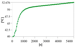 |
| 0-20 | 61.4 | 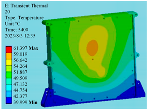 | 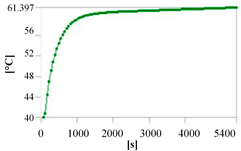 |
| 0-30 | 55.1 | 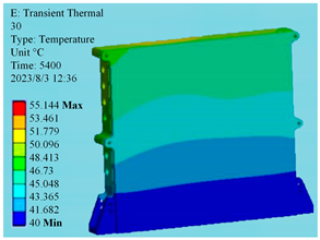 | 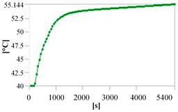 |
| Equipment | 68.1 | 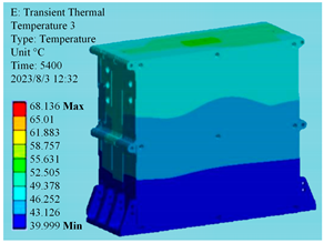 | 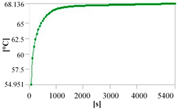 |
| Component Name | Thermal Resistance (°C/W) | Average Heat Consumption/W | Component Shell Temperature (°C) | Component Junction Temperature (°C) |
|---|---|---|---|---|
| 0-10-DCDC | / | 10 | 42.4 | / |
| 0-10-FPGA | / | 3 | 50.7 | / |
| 0-10-HT1H | / | 2 | 49.8 | / |
| 0-10-TPS54527 | 5.2 | 0.37 | 55.3 | 57.3 |
| 0-20-PAF | 6.5 | 0.1 | 53.8 | 54.5 |
| 0-20-PAR | 35 | 0.015 | 49.8 | 50.3 |
| 0-20-CLOCK | 6.9 | 1.5 | 60.6 | 71 |
| 0-20-SoC | 3.4 | 6.5 | 63 | 85.1 |
| 0-20-DDR3 | 6.5 | 2.1 | 58.2 | 71.9 |
| 0-20-AD | 0.6 | 1.4 | 65.3 | 66.1 |
| 0-20-DCDC | 7.4 | 1 | 54.4 | 61.8 |
| 0-30-CX6672 | / | 5 | 52.9 | / |
| 0-30-TPS54527 | 5.2 | 0.67 | 66.8 | 70.3 |
| 0-30-RM500Q | / | 4.5 | 46.9 | / |
| 0-30-TPS54527 | 5.2 | 0.15 | 48.8 | 49.6 |
| 0-30-RD05W3035 | / | 0.55 | 47.6 | / |
| 0-30-TPS54527 | 5.2 | 0.15 | 49.2 | 50.0 |
| Component Name | Thermal Equilibrium Temperature/°C | Temperature Cloud Graph | Temperature Change Curve |
|---|---|---|---|
| 0-10 | 53.7 | 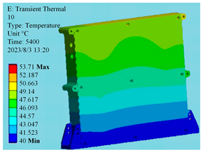 | 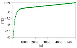 |
| 0-20 | 61.6 | 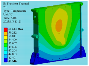 | 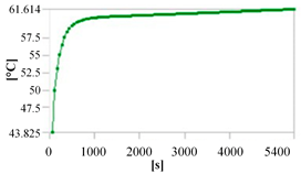 |
| 0-30 | 56.0 | 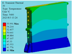 | 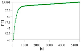 |
| Equipment | 67.2 |  | 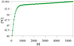 |
| Component Name | Thermal Resistance (°C/W) | Average Heat Consumption/W | Component Shell Temperature (°C) | Component Junction Temperature (°C) |
|---|---|---|---|---|
| 0-10-DCDC | / | 10 | 40.7 | / |
| 0-10-FPGA | / | 3 | 44.2 | / |
| 0-10-HT1H | / | 2 | 47.9 | / |
| 0-10-TPS54527 | 5.2 | 0.37 | 53.9 | 55.9 |
| 0-20-PAF | 6.5 | 0.1 | 45.2 | 45.9 |
| 0-20-PAR | 35 | 0.015 | 41.9 | 42.4 |
| 0-20-CLOCK | 6.9 | 1.5 | 45.9 | 56.3 |
| 0-20-SoC | 3.4 | 6.5 | 48.3 | 70.4 |
| 0-20-DDR3 | 6.5 | 2.1 | 50.7 | 64.4 |
| 0-20-AD | 0.6 | 1.4 | 53.6 | 54.4 |
| 0-20-DCDC | 7.4 | 1 | 50.1 | 57.5 |
| 0-30-CX6672 | / | 5 | 46.6 | / |
| 0-30-TPS54527 | 5.2 | 0.67 | 66.3 | 69.8 |
| 0-30-RM500Q | / | 4.5 | 47.3 | / |
| 0-30-TPS54527 | 5.2 | 0.5 | 60.5 | 63.1 |
| 0-30-RD05W3035 | / | 0.55 | 41.3 | / |
| 0-30-TPS54527 | 5.2 | 0.15 | 44.1 | 44.9 |
| Component Name | Thermal Equilibrium Temperature/°C | Temperature Cloud Graph | Temperature Change Curve |
|---|---|---|---|
| 0-10 | 45.6 |  | 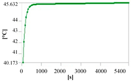 |
| 0-20 | 48.3 | 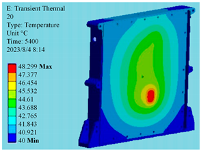 | 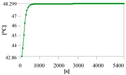 |
| 0-30 | 45.0 | 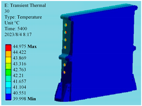 | 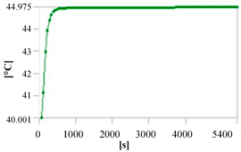 |
| Equipment | 66.3 | 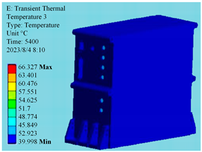 | 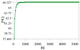 |
Disclaimer/Publisher’s Note: The statements, opinions and data contained in all publications are solely those of the individual author(s) and contributor(s) and not of MDPI and/or the editor(s). MDPI and/or the editor(s) disclaim responsibility for any injury to people or property resulting from any ideas, methods, instructions or products referred to in the content. |
© 2024 by the authors. Licensee MDPI, Basel, Switzerland. This article is an open access article distributed under the terms and conditions of the Creative Commons Attribution (CC BY) license (https://creativecommons.org/licenses/by/4.0/).
Share and Cite
Qian, J.; Liu, M.; Zhao, Q.; Luo, S.; Xia, F.; Bai, Y. Research on the Heat Dissipation in Aviation-Integrated Communication Equipment Based on Graphene Films. Aerospace 2024, 11, 483. https://doi.org/10.3390/aerospace11060483
Qian J, Liu M, Zhao Q, Luo S, Xia F, Bai Y. Research on the Heat Dissipation in Aviation-Integrated Communication Equipment Based on Graphene Films. Aerospace. 2024; 11(6):483. https://doi.org/10.3390/aerospace11060483
Chicago/Turabian StyleQian, Jingyi, Min Liu, Quan Zhao, Shimiao Luo, Feng Xia, and Yunfeng Bai. 2024. "Research on the Heat Dissipation in Aviation-Integrated Communication Equipment Based on Graphene Films" Aerospace 11, no. 6: 483. https://doi.org/10.3390/aerospace11060483
APA StyleQian, J., Liu, M., Zhao, Q., Luo, S., Xia, F., & Bai, Y. (2024). Research on the Heat Dissipation in Aviation-Integrated Communication Equipment Based on Graphene Films. Aerospace, 11(6), 483. https://doi.org/10.3390/aerospace11060483