


Propulsion Technologies for CubeSats: Review

Abstract
:1. Introduction
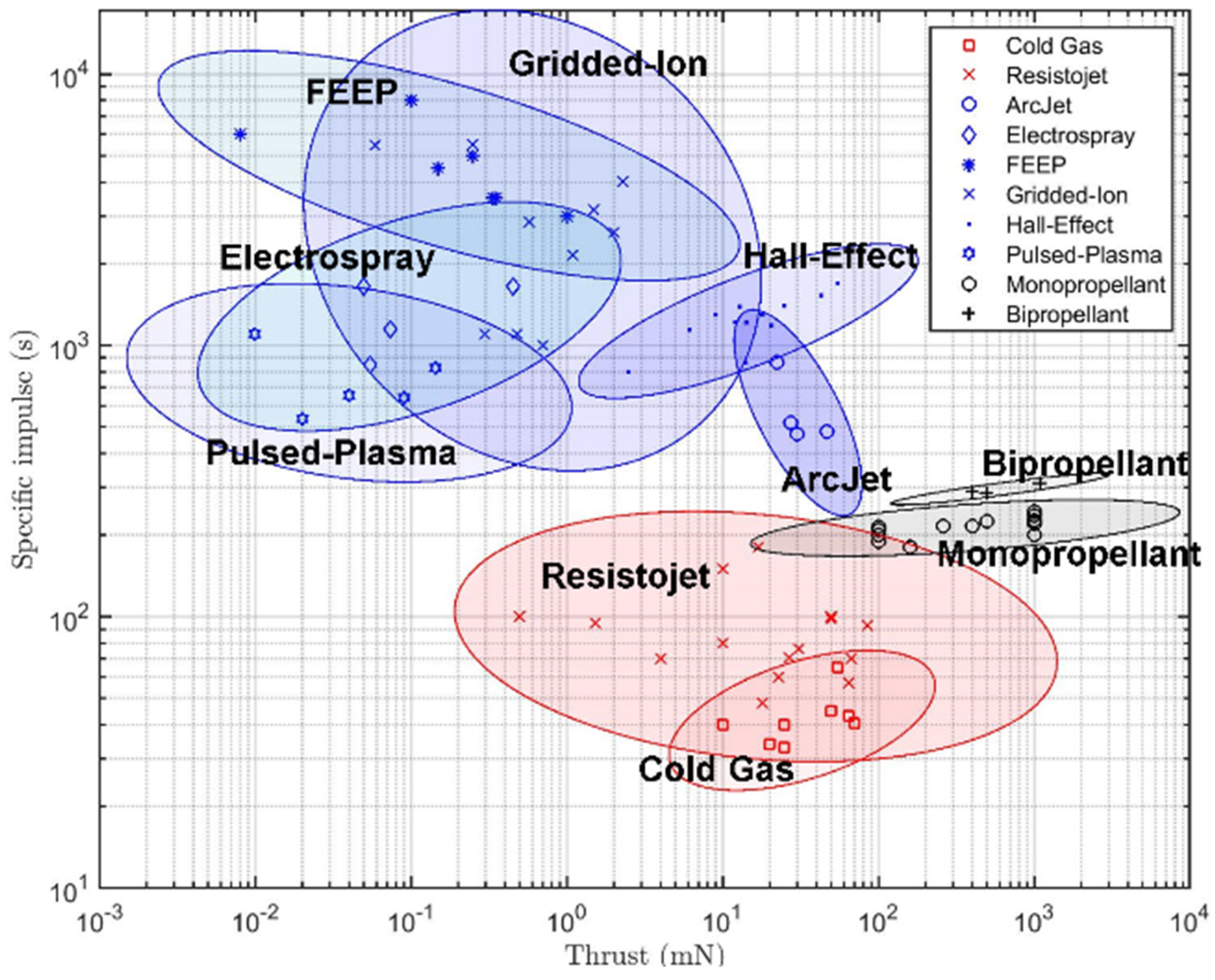
2. Propulsion Performance
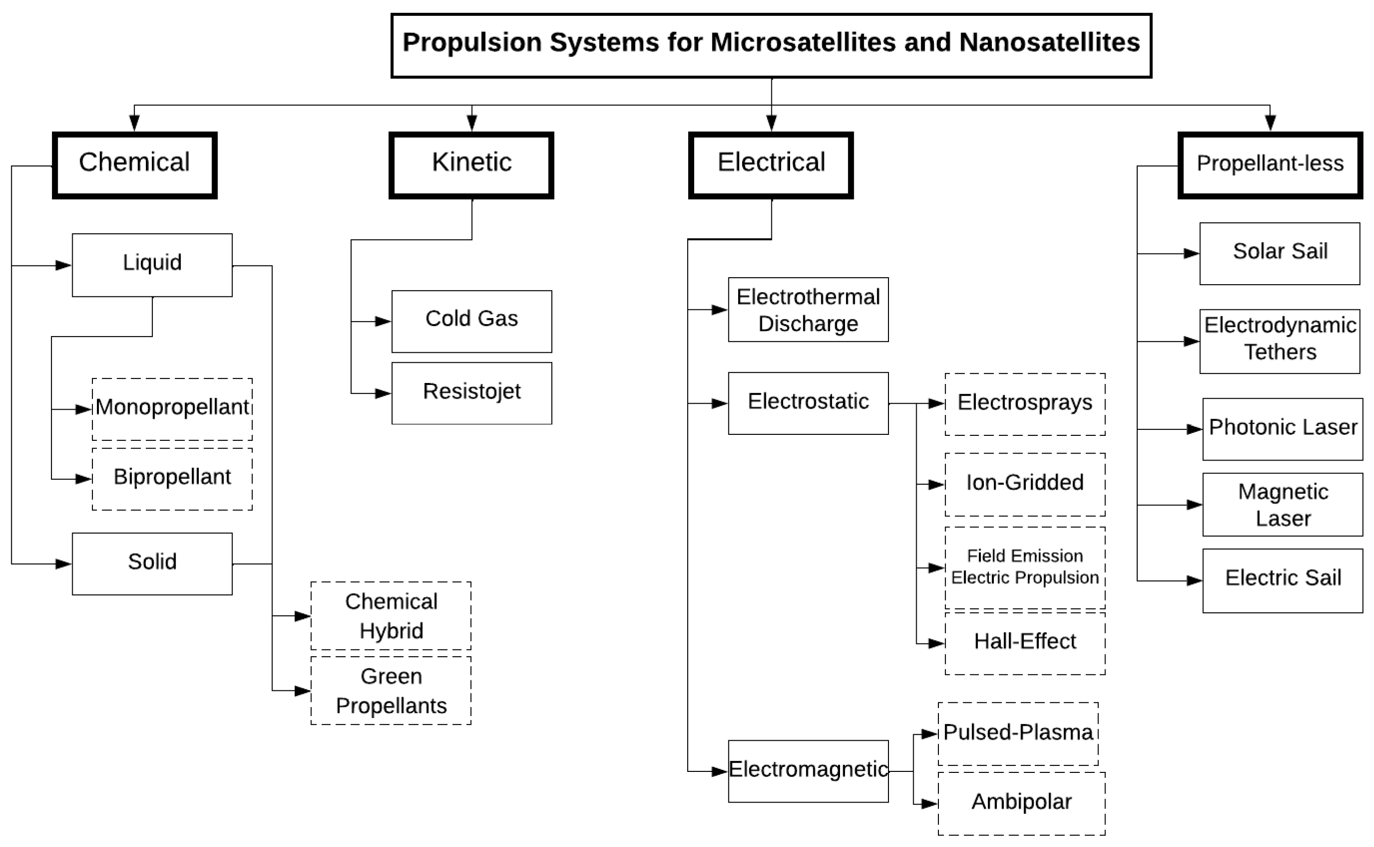
3. Propulsion Technology Types
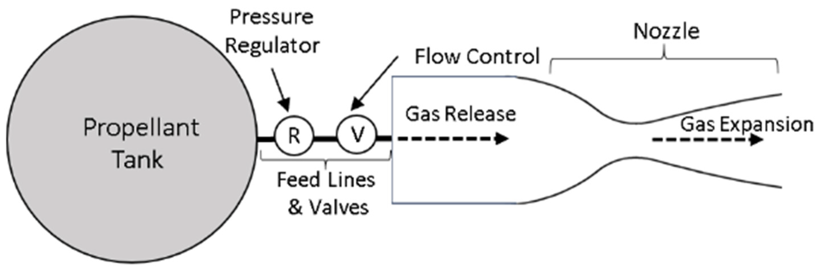
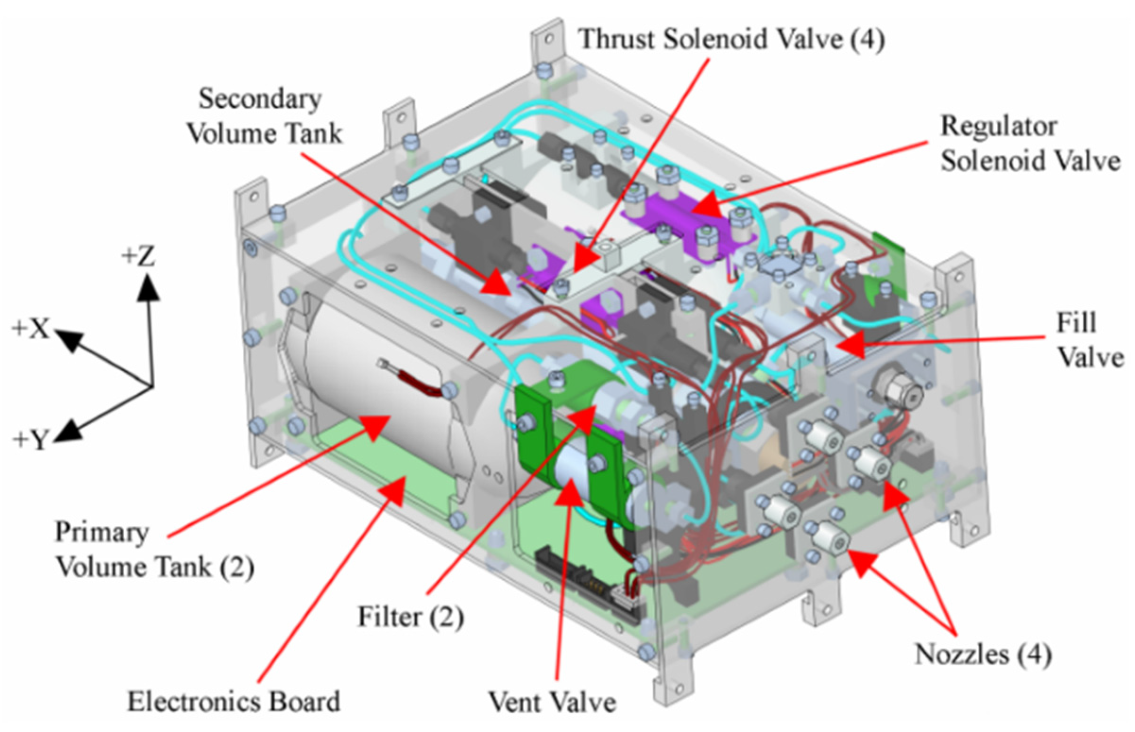
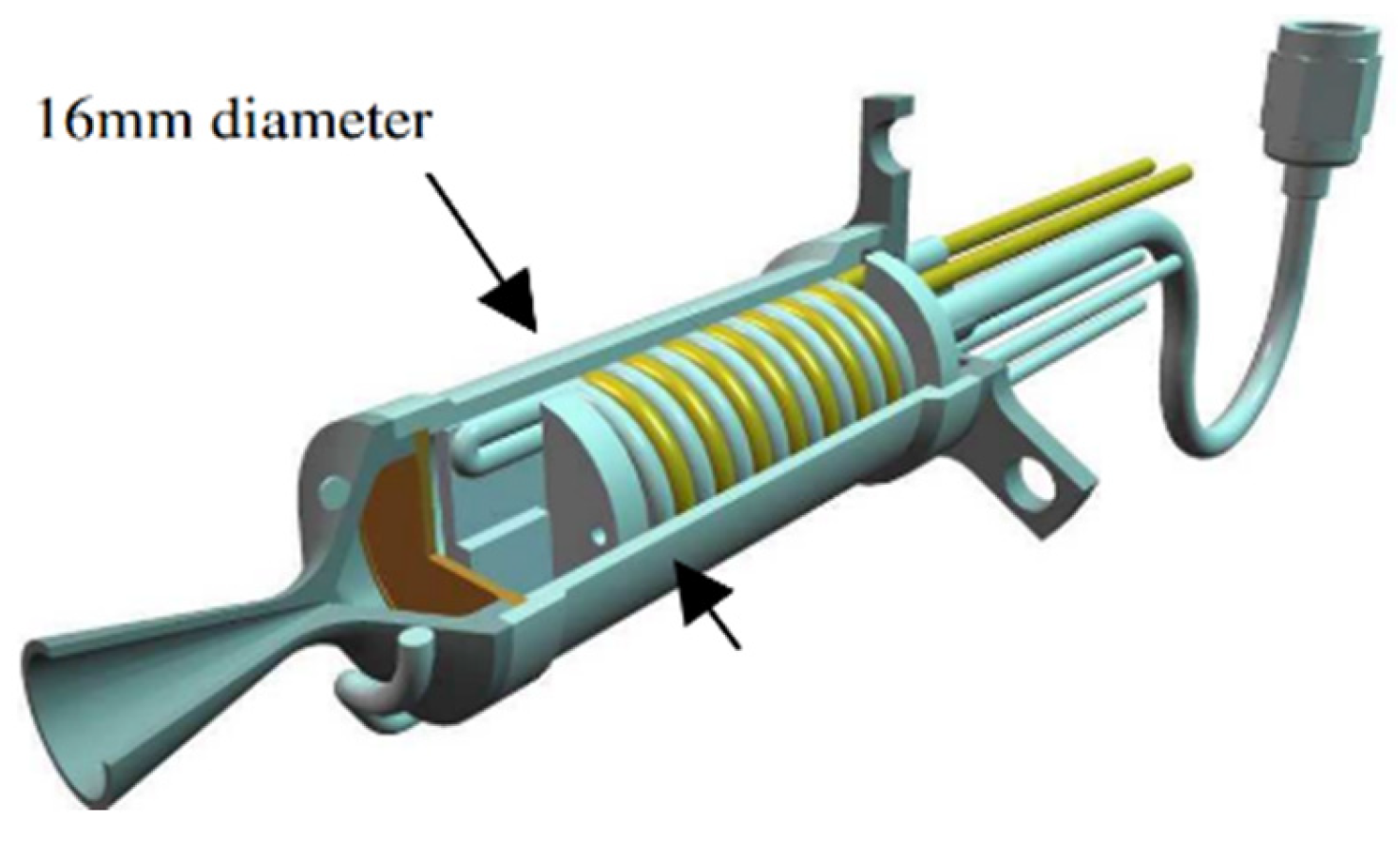
3.1. Kinetic Propulsion
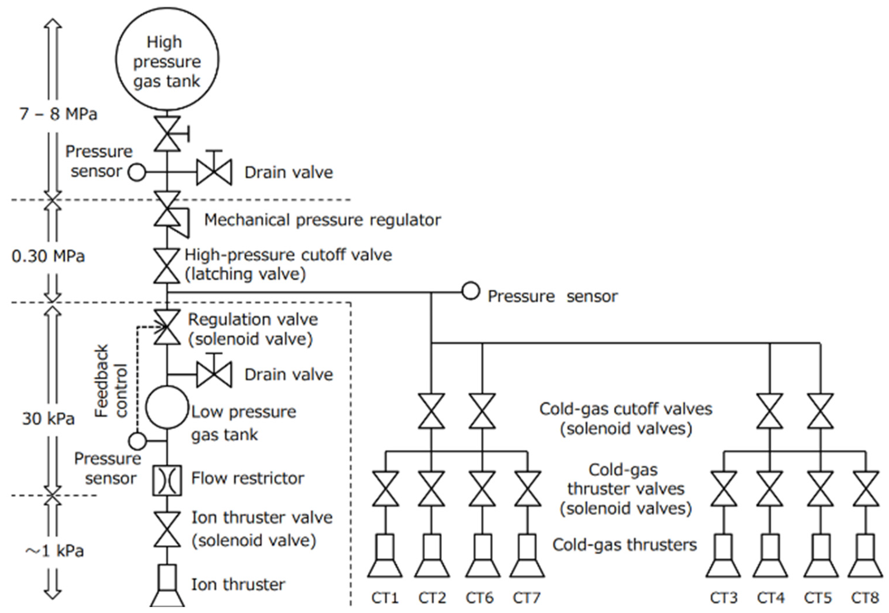
3.1.1. Cold Gas/Warm Gas
3.1.2. Resistojet
3.2. Chemical Propulsion
3.2.1. Monopropellant
3.2.2. Bipropellant
3.2.3. Solid
3.2.4. Hybrid Chemical
3.3. Electric Propulsion
3.3.1. Electrothermal Discharge
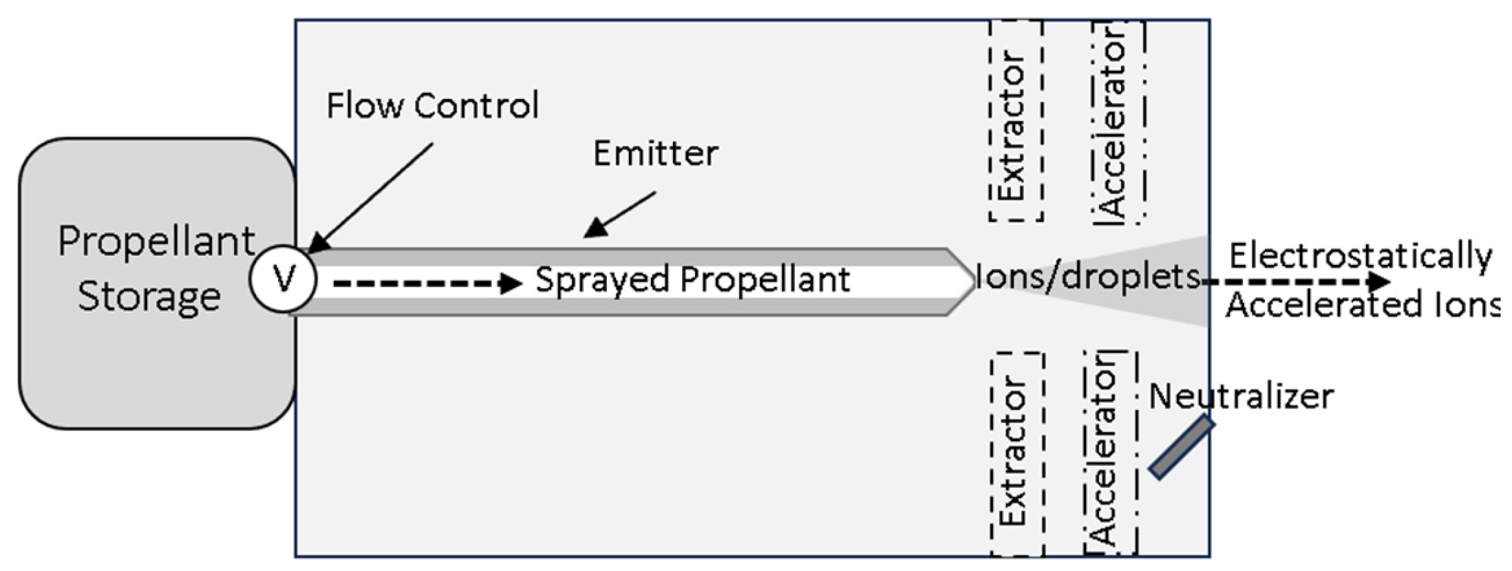
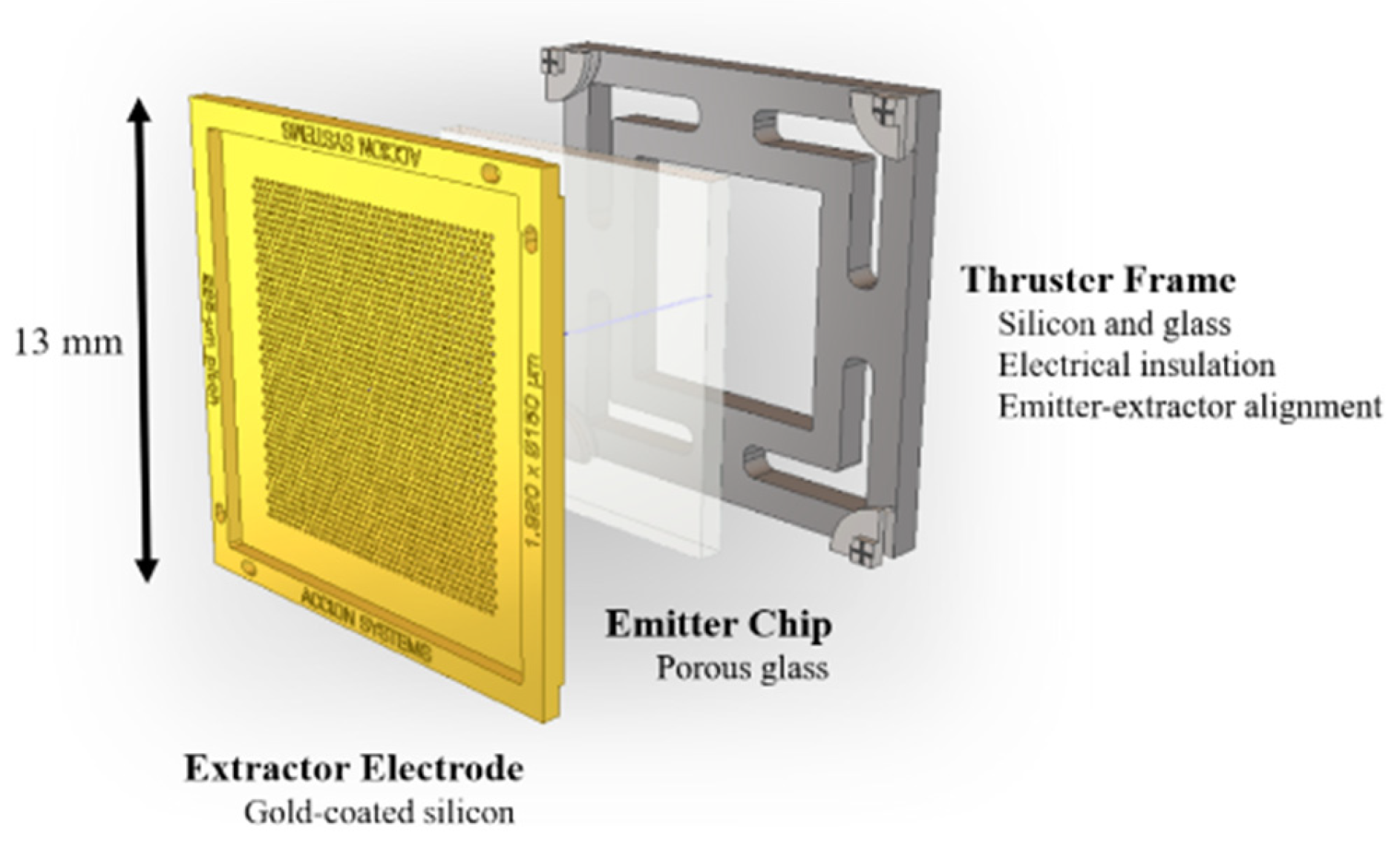
3.3.2. Electrospray
3.3.3. FEEP
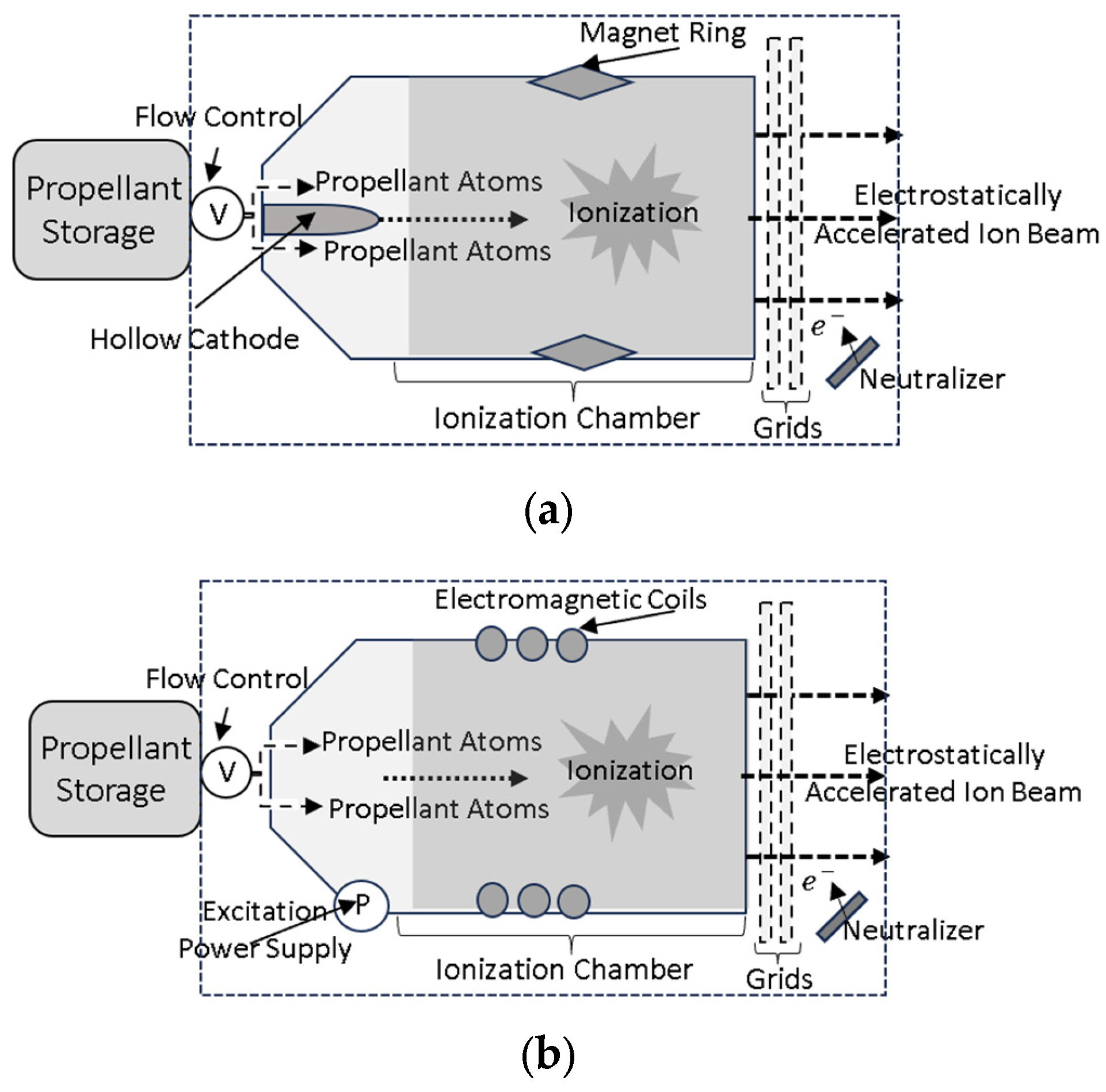
3.3.4. Gridded Ion
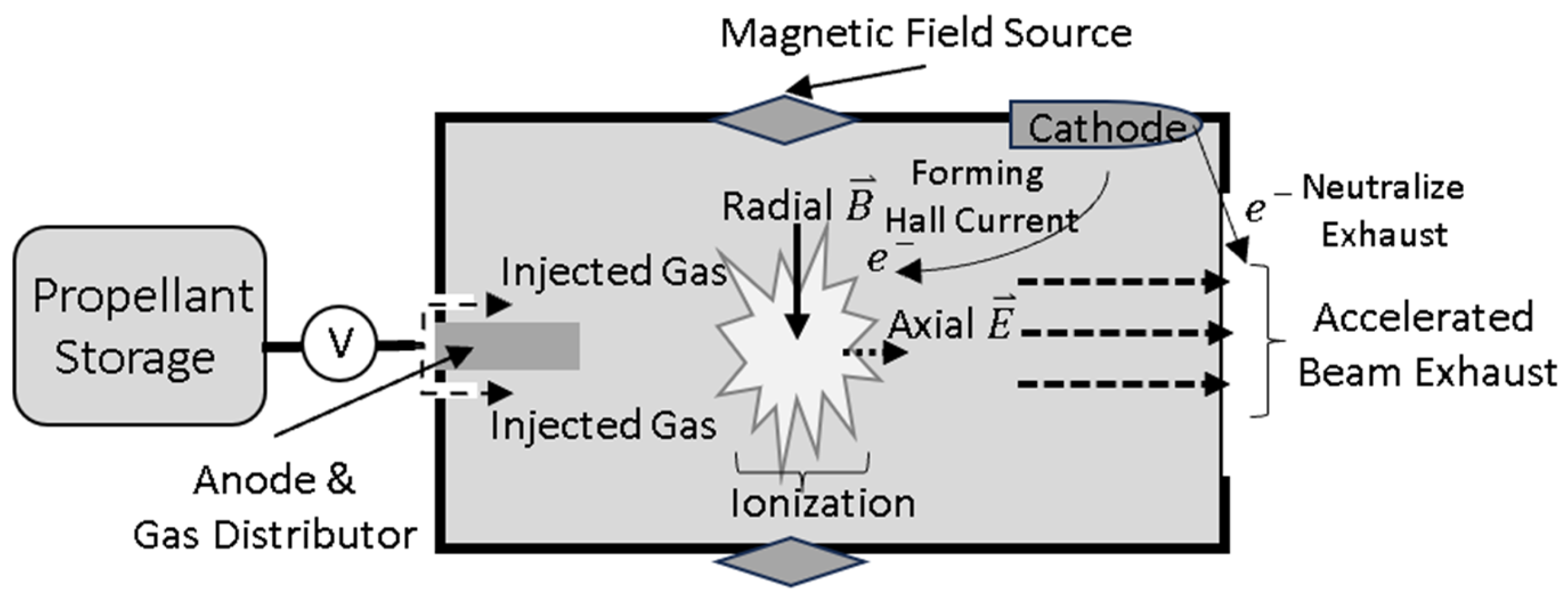
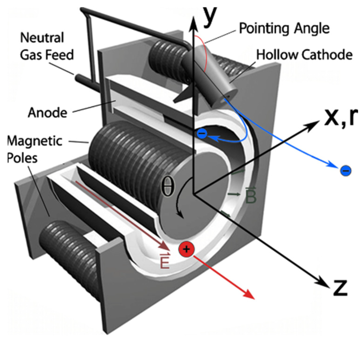
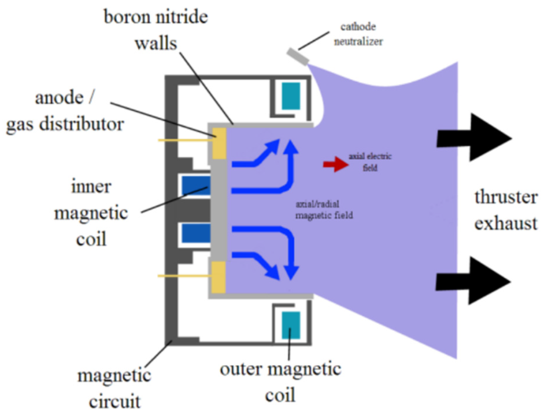
3.3.5. Hall Effect
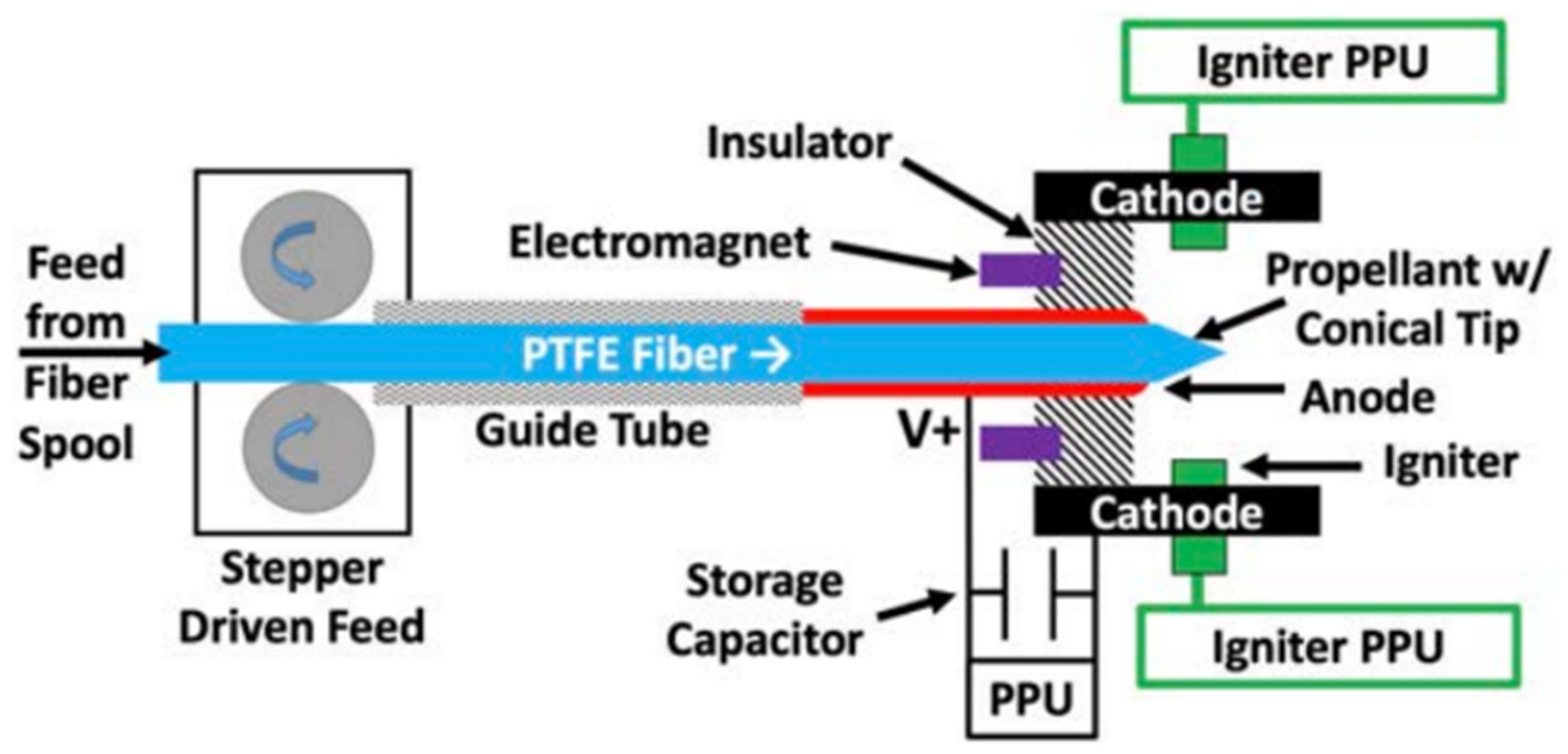
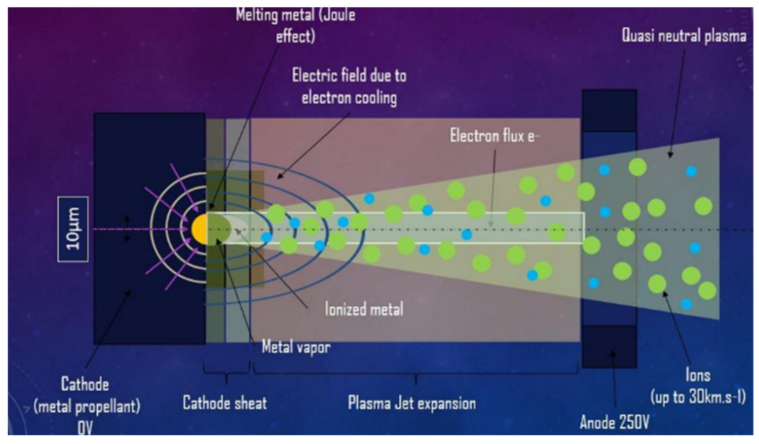
3.3.6. Pulsed Plasma and Vacuum Arc
3.3.7. Ambipolar
3.4. Propellant-Less
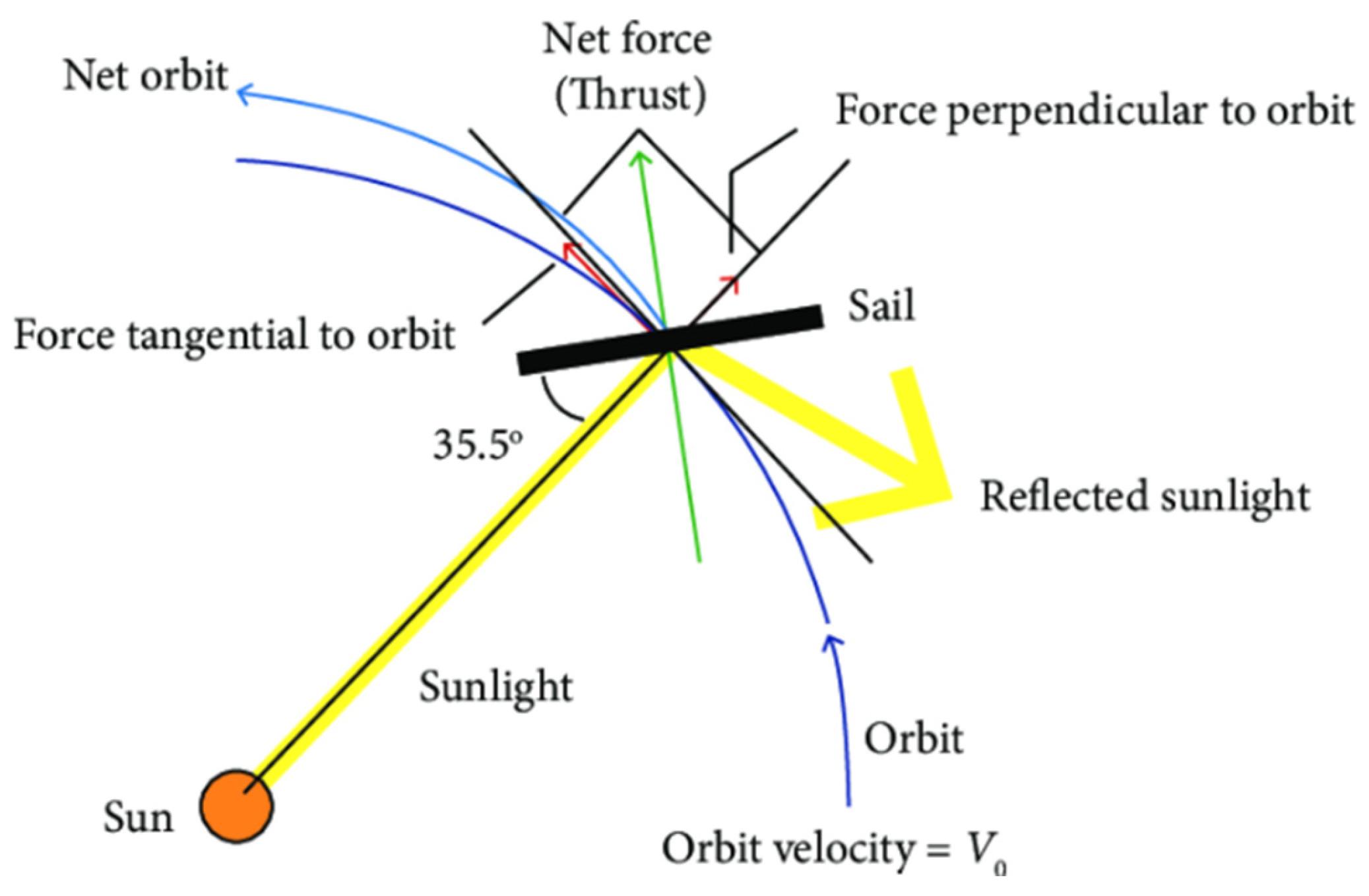
3.4.1. Solar Sail
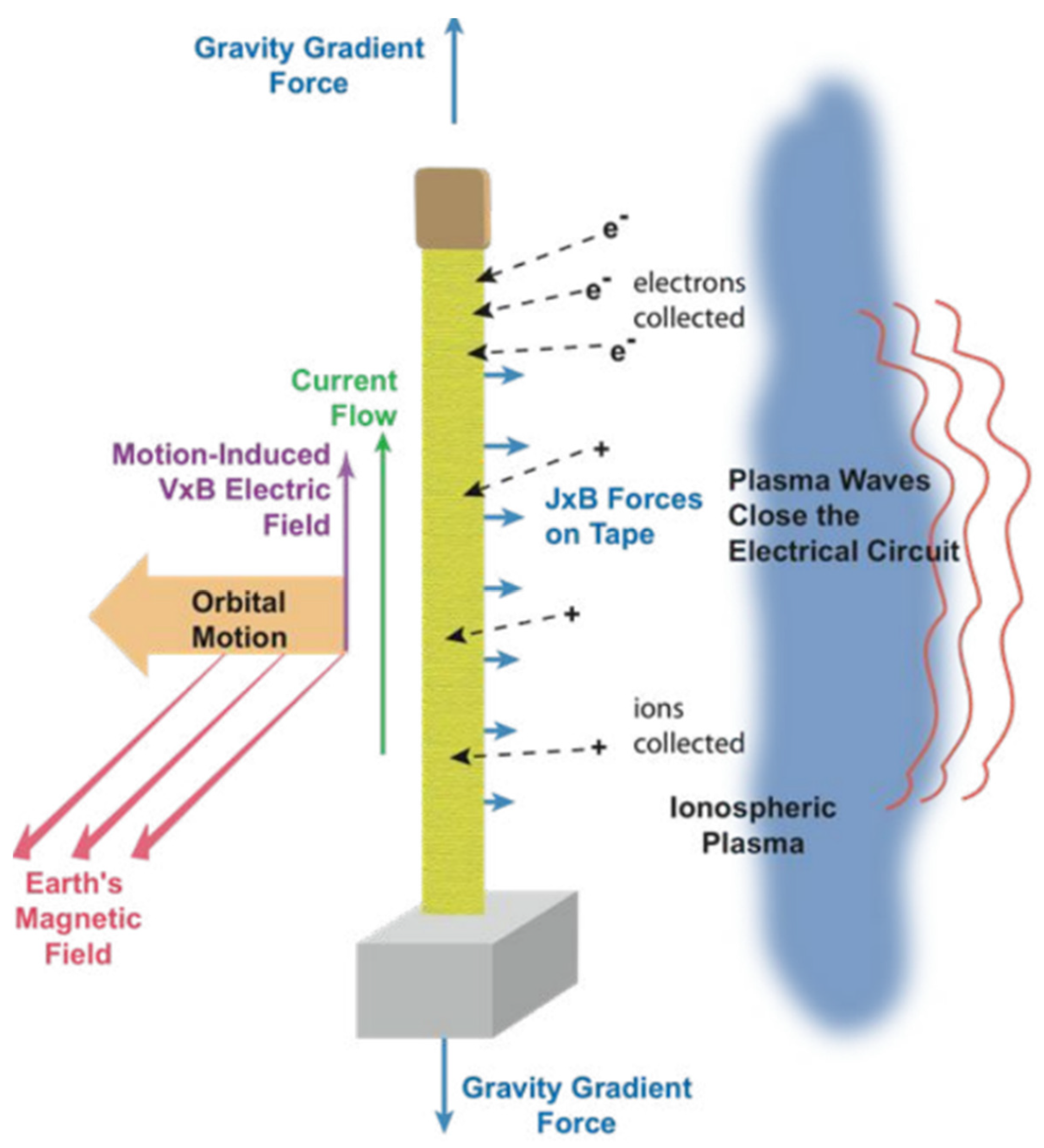
3.4.2. Electrodynamic Tethers
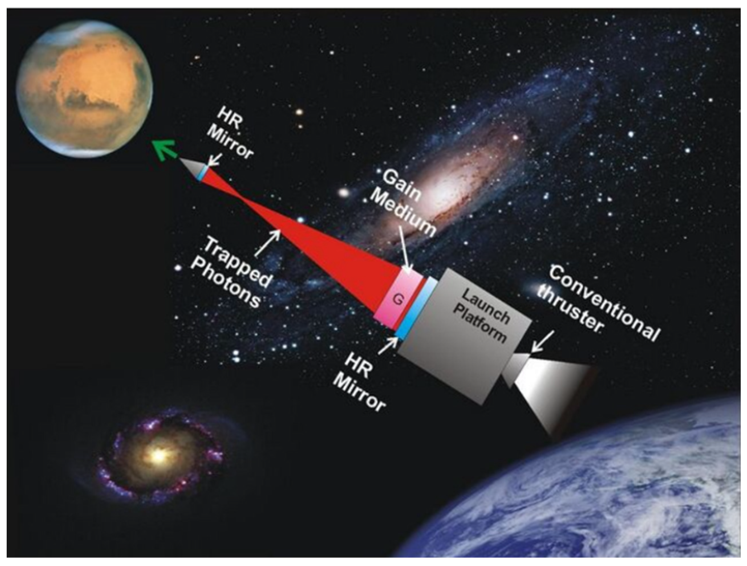
3.4.3. Other Propellent-Less Concepts
3.5. Multimode and Hybrid Systems
4. Performance of Propulsion Technologies
5. Future of Small Satellite Propulsion
6. Conclusions
Funding
Acknowledgments
Conflicts of Interest
References
- NASA. What are SmallSats and CubeSats? NASA: Washington, DC, USA, 2015.
- Kulu, E. Nanosats Database|Constellations, Companies, Technologies and More. Available online: https://www.nanosats.eu/ (accessed on 4 September 2023).
- Humble, R.W.; Gary, H.N.; Larson, W.J. Space Propulsion Analysis and Design; McGraw Hill: New York, NY, USA, 1995; pp. 10–11. [Google Scholar]
- Legge, R.S.; Clements, E.B.; Shabshelowitz, A. Enabling microsatellite maneuverability: A survey of microsatellite propulsion technologies. In Proceedings of the 2017 IEEE MTT-S International Microwave Symposium (IMS), Honololu, HI, USA, 4–9 June 2017; pp. 229–232. [Google Scholar]
- Lide, D.R. CRC Handbook of Chemistry and Physics, 85th ed.; CRC Press: Boca Raton, FL, USA, 2004. [Google Scholar]
- R-236fa. Climalife. 2013. Available online: https://climalife.dehon.com/uploads/media/3/241/241_1746_r236fa-fd-en-13.pdf (accessed on 4 September 2023).
- Seubert, C.; Pernicka, H.; Norgren, C. Refrigerant-based propulsion system for small spacecraft. In Proceedings of the 43rd AIAA/ASME/SAE/ASEE Joint Propulsion Conference & Exhibit, Cincinnati, OH, USA, 8–11 July 2007; p. 5131. [Google Scholar]
- Pahl, R.A. Integration and test of a refrigerant-based cold-gas propulsion system for small satellites. In Proceedings of the 24th Annual AIAA/USU Conference on Small Satellites, Logan, UT, USA, 9–12 August 2010. [Google Scholar]
- Thermodynamic Properties of HFC-236fa (1,1,1,3,3,3-hexafluoropropane). DuPont Fluorochemicals. Available online: http://www.allchemi.com/download/tables/HFC-236fa-SI.PDF (accessed on 6 October 2023).
- Steyn, W.H.; Hashida, Y. In-orbit attitude and orbit control commissioning of UoSAT-12. Spacecr. Guid. Navig. Control Syst. 2000, 425, 95. [Google Scholar]
- El-Bordany, R. In Orbit Calibration of Satellite Inertia Matrix and Thruster Coefficients; University of Surrey: Guildford, UK, 2001. [Google Scholar]
- Ward, J.; Sweeting, M. First in-orbit results from the UoSAT-12 minisatellite. In Proceedings of the Small Satellite Conference, Logan, UT, USA, 10–13 August 2009. [Google Scholar]
- Gibbon, D.; Underwood, C. Low Cost Butane Propulsion Systems for Small Spacecraft, 15th AIAA. In Proceedings of the USU Conference on Small Satellites, Logan, UT, USA, 13–16 August 2001. [Google Scholar]
- Gibbon, D.A.; Ward, J.A.; Kay, N. The design, development and testing of a propulsion system for the SNAP-1 nanosatellite. In Proceedings of the Small Satellite Conference, Logan, UT, USA, 16–18 October 2000. [Google Scholar]
- Bzibziak, R. Update of cold gas propulsion at Moog. In Proceedings of the 36th AIAA/ASME/SAE/ASEE Joint Propulsion Conference and Exhibit, Las Vegas, NV, USA, 24–28 July 2000; p. 3718. [Google Scholar]
- Schelkle, M. The GRACE cold gas attitude and orbit control system. Spacecr. Propuls. 2000, 465, 769. [Google Scholar]
- Cardin, J.; Coste, K.; Williamson, D.; Gloyer, P. A cold gas micro-propulsion system for cubesats. In Proceedings of the Small Satellite Conference, Logan, UT, USA, 30 June 2003. [Google Scholar]
- Hinkley, D. A novel cold gas propulsion system for nanosatellites and picosatellites. In Proceedings of the Small Satellite Conference, Logan, UT, USA, 22 May 2008. [Google Scholar]
- VACCO Industries Micro Propulsion Systems. Available online: https://www.vacco.com/images/uploads/pdfs/MicroPropulsionSystems.pdf (accessed on 4 September 2023).
- VACCO Industries VACCO ChEMSTM. Available online: http://mstl.atl.calpoly.edu/~workshop/archive/2015/Spring/Day 3/0920-Day-Micro Propulsion Systems.pdf (accessed on 4 September 2023).
- Carlisle, C.; Webb, E.H. Space Technology 5-A Successful Micro-Satellite Constellation Mission. In Proceedings of the 21st Annual AIAA/USU Conference on Small Satellites, Logan, UT, USA, 13–16 August 2007. no. SSC07-VII-6. [Google Scholar]
- Sarda, K.; Grant, C.; Eagleson, S.; Kekez, D.; Zee, R. Canadian advanced nanospace experiment 2: On-orbit experiences with a three-kilogram satellite. In Proceedings of the Small Satellite Conference, Logan, UT, USA, 22 May 2008. [Google Scholar]
- Bonin, G.; Roth, N.; Armitage, S.; Newman, J.; Risi, B.; Zee, R.E. CanX–4 and CanX–5 precision formation flight: Mission accomplished! In Proceedings of the Small Satellite Conference, Logan, UT, USA, 10 August 2015. [Google Scholar]
- Grönland, T.-A.; Rangsten, P.; Nese, M.; Lang, M. Miniaturization of components and systems for space using MEMS-technology. Acta Astronaut. 2007, 61, 228–233. [Google Scholar] [CrossRef]
- Persson, S.; D’Amico, S.; Harr, J. Flight results from prisma formation flying and rendezvous demonstration mission. In Proceedings of the Small Satellite Conference, Logan, UT, USA, 19 May 2010. [Google Scholar]
- Wu, S.; Chen, W.; Chao, C. The STU-2 CubeSat mission and in-orbit test results. In Proceedings of the Small Satellite Conference 2016, Logan, UT, USA, 11 October 2016. [Google Scholar]
- Kvell, U.; Puusepp, M.; Kaminski, F.; Past, J.-E.; Palmer, K.; Grönland, T.-A.; Noorma, M. Nanosatellite orbit control using MEMS cold gas thrusters. Proc. Est. Acad. Sci. 2014, 63, 279. [Google Scholar] [CrossRef]
- Palmer, K.; Li, Z.; Wu, S. In-Orbit Demonstration of a MEMS-based Micropropulsion system for Cubesats. In Proceedings of the Small Satellite Conference 2016, Logan, UT, USA, 11 October 2016. [Google Scholar]
- Pérez, L.L.; Koch, P.; Smith, D.; Walker, R. GOMX-4 the most advance nanosatellite mission for IOD purposes. Proc. 4S Symp. 2018, 125, 12–30. [Google Scholar]
- GomSpace. Astrocast Signs Contract with GomSpace Sweden to Deliver Propulsion Systems. 2018. Available online: https://gomspace.com/news/astrocast-signs-contract-with-gomspace-sweden.aspx (accessed on 25 September 2023).
- Guo, J.; Bouwmeester, J.; Gill, E. In-orbit results of Delfi-n3Xt: Lessons learned and move forward. Acta Astronaut. 2016, 121, 39–50. [Google Scholar] [CrossRef]
- Manzoni, G.; Brama, Y.L. Cubesat micropropulsion characterization in low earth orbit. In Proceedings of the Small Satellite Conference, Logan, UT, USA, 10 August 2015. [Google Scholar]
- Arestie, S.; Lightsey, E.G.; Hudson, B. Development of a modular, cold gas propulsion system for small satellite applications. J. Small Satell. 2012, 1, 63–74. [Google Scholar]
- Past Missions. University of Texas at Austin. Available online: https://sites.utexas.edu/tsl/past-missions/ (accessed on 25 September 2023).
- Imken, T.K.; Stevenson, T.H.; Lightsey, E.G. Design and testing of a cold gas thruster for an interplanetary CubeSat mission. J. Small Satell. 2015, 4, 371–386. [Google Scholar]
- NASA C-POD Micro CubeSat Propulsion System. VACCO Industries. Available online: https://cubesat-propulsion.com/reaction-control-propulsion-module/ (accessed on 25 September 2023).
- NASA. CubeSat Proximity Operations Demonstration (CPOD). NASA. Available online: https://www.nasa.gov/directorates/spacetech/small_spacecraft/cpod_project.html (accessed on 25 September 2023).
- Rowen, D.; Hardy, B.; Coffman, C.; Hinkley, D.; Welle, R.; Janson, S. The NASA optical communications and sensor demonstration program: Proximity operations. In Proceedings of the Small Satellite Conference, Logan, UT, USA, 4 August 2018. [Google Scholar]
- Gangestad, J.W.; Venturini, C.C.; Hinkley, D.A.; Kinum, G. A sat-to-sat inspection demonstration with the AeroCube-10 1.5 U CubeSats. In Proceedings of the 35th Annual Small Satellite Conference, Virtual, 7–12 August 2021. [Google Scholar]
- Piergentili, F.; Balucani, M.; Crescenzi, R.; Piattoni, J.; Santoni, F.; Betti, B.; Onofri, M. MEMS cold gas microthruster on Ursa Maior CubeSat. In Proceedings of the 64th International Astronautical Congress, Beijing, China, 23–27 September 2013. [Google Scholar]
- Klesh, A.T.; Baker, J.; Krajewski, J. MarCO: Flight review and lessons learned. In Proceedings of the Small Satellite Conference, Logan, UT, USA, 9 August 2019. [Google Scholar]
- JPL MarCO Micro CubeSat Propulsion System. VACCO Industries. Available online: https://cubesat-propulsion.com/jpl-marco-micro-propulsion-system/ (accessed on 25 September 2023).
- Martínez, J.M.; Rafalskyi, D.; Rossi, E.Z.; Aanesland, A. Development, Qualification and First Flight Data of the Iodine Based Cold Gas Thruster for Cubesats; IAA: Rome, Italy, 2019. [Google Scholar]
- Martínez, J.M.; Rafalskyi, D.; Aanesland, A.; Laurand, X.; Martinez, S.V.; Quinsac, G. An off-axis iodine propulsion system for the robusta-3A mission. In Proceedings of the Small Satellite Conference, Logan, UT, USA, 10 March 2020. [Google Scholar]
- Aslan, S.; Fares, J.; DiStefano, M.; Peck, M.A. An adaptable, modular cold-gas propulsion system for small satellite applications. In Proceedings of the AIAA Scitech 2020 Forum, Orlando, FL, USA, 6–10 January 2020; p. 1666. [Google Scholar] [CrossRef]
- Clark, S. Virgin Orbit Celebrates Third Successful Launch in a Row. Spaceflight Now. 13 January 2022. Available online: https://spaceflightnow.com/2022/01/13/virgin-orbit-celebrates-third-successful-launch-in-a-row/ (accessed on 25 September 2023).
- Adelis-SAMSON. Asher Space Research Institute. Available online: https://asri.institute/space-missions/adelis-samson/ (accessed on 25 September 2023).
- Zaberchik, M.; Lev, D.R.; Edlerman, E.; Kaidar, A. Fabrication and testing of the cold gas propulsion system flight unit for the adelis-SAMSON nano-satellites. Aerospace 2019, 6, 91. [Google Scholar] [CrossRef]
- Simonetti, S.; Di Tana, V.; Miglioretti, F.; Cotugno, B.; Pirrotta, S.; Amoroso, M.; Pizzurro, S.; Impresario, G. LICIACube on DART mission: An asteroid impact captured by Italian small satellite technology. In Proceedings of the Small Satellite Conference, Logan, UT, USA, 10 March 2020. [Google Scholar]
- Williams, D.R. LICIACube. NASA. Available online: https://nssdc.gsfc.nasa.gov/nmc/spacecraft/display.action?id=2021-110C (accessed on 25 September 2023).
- IANUS & PERSEUS Cold Gas. T4i. Available online: https://www.t4innovation.com/ianus-perseus-cold-gas/ (accessed on 25 September 2023).
- Skidmore, L.; Lightsey, E.G. Design of a Cold Gas Propulsion System for the SunRISE Mission. Master’s Thesis, Georgia Institute of Technology, Atlanta, GA, USA, 2021. [Google Scholar]
- Dailey, J. AFRL Celebrates Launch of Small-Sat Ascent to GEO Space. The Air Force Research Laboratory. 2021. Available online: https://www.afrl.af.mil/News/Article/2859902/afrl-celebrates-launch-of-small-sat-ascent-to-geo-space/ (accessed on 26 September 2023).
- Lightsey, E.G.; Stevenson, T.; Sorgenfrei, M. Development and testing of a 3-d-printed cold gas thruster for an interplanetary cubesat. Proc. IEEE 2018, 106, 379–390. [Google Scholar] [CrossRef]
- Hart, S.T.; Lightsey, E.G. Design of the VISORS and SWARM-EX Propulsion Systems. Master’s Thesis, Georgia Tech, Atlanta, GA, USA, 2010. [Google Scholar]
- NEA Scout Propulsion System. VACCO Industries. Available online: https://cubesat-propulsion.com/nea-scout-propulsion-system/ (accessed on 26 September 2023).
- CuSP Propulsion System. VACCO Industries. Available online: https://cubesat-propulsion.com/cusp-propulsion-system/ (accessed on 26 September 2023).
- Sweeting, M.N.; Lawrence, T.; Sellers, J.; Leduc, J. Low-cost orbit manoeuvres for minisatellites using novel water resistojet thrusters. In Proceedings of the IAF, International Astronautical Congress, 49th, Melbourne, Australia, 28 September–2 October 1998. [Google Scholar]
- Darfilal; Gibbon, D. Ground and flight tests of AlSat-1B butane propulsion system. Propuls. Power Res. 2022, 11, 74–84. [Google Scholar] [CrossRef]
- Amri, R.; Gibbon, D. In orbit performance of butane propulsion system. Adv. Sp. Res. 2012, 49, 648–654. [Google Scholar] [CrossRef]
- Gibbon, D.; Coxhill, I.; Nicolini, D.; Correia, R.; Page, J. The design, development and in-flight operation of a water resistojet micropropulsion system. In Proceedings of the 40th AIAA/ASME/SAE/ASEE Joint Propulsion Conference and Exhibit, Fort Lauderdale, FL, USA, 12 July 2004; p. 3798. [Google Scholar]
- Romei, F.; Grubisic, A.; Gibbon, D.; Lane, O.; Hertford, R.A.; Roberts, G.T. A thermo-fluidic model for a low power xenon resistojet. In Proceedings of the Joint Conference of 30th ISTS, 34th IEPC and 6th NSAT, Hyogo-Kobe, Japan, 4–10 July 2015. 15p. [Google Scholar]
- Ketsdever, A.D.; Wadsworth, D.C.; Vargo, S.E.; Muntz, E.P.; Air Force Research Lab Edwards Afb Ca Propulsion Directorate West. Design, optimization and fabrication of a free molecule micro-resistojet for microspacecraft thrust generation. In Proceedings of the Small Satellite Conference, Logan, UT, USA, 20 November 1998. [Google Scholar]
- Ketsdever, A.D.; Lee, R.H.; Lilly, T.C. Performance testing of a microfabricated propulsion system for nanosatellite applications. J. Micromech. Microeng. 2005, 15, 2254. [Google Scholar] [CrossRef]
- Lee, R.; Bauer, A.; Killingsworth, M.; Lilly, T.; Duncan, J.; Ketsdever, A. Performance characterization of the free molecule micro-resistojet utilizing water propellant. In Proceedings of the 43rd AIAA/ASME/SAE/ASEE Joint Propulsion Conference & Exhibit, Cincinnati, OH, USA, 8–11 July 2007; p. 5185. [Google Scholar]
- Pallichadath, V.; Turmaine, L.; Melaika, A.; Gelmi, S.; Ramisa, M.V.; Rijlaarsdam, D.; Silva, M.A.C.; Guerrieri, D.C.; Uludag, M.S.; Zandbergen, B. In-orbit micro-propulsion demonstrator for PICO-satellite applications. Acta Astronaut. 2019, 165, 414–423. [Google Scholar] [CrossRef]
- Cervone, A.; Zandbergen, B.; Guerrieri, D.C.; De Athayde Costa e Silva, M.; Krusharev, I.; Van Zeijl, H. Green micro-resistojet research at Delft University of Technology: New options for Cubesat propulsion. CEAS Sp. J. 2017, 9, 111–125. [Google Scholar] [CrossRef]
- Moore, G.; Holemans, W.; Huang, A.; Lee, J.; McMullen, M.; White, J.; Twiggs, R.; Malphrus, B.; Fite, N.; Klumpar, D. 3D Printing and MEMS Propulsion for the RAMPART 2U CUBESAT. In Proceedings of the Small Satellite Conference, Logan, UT, USA, 19 May 2010. [Google Scholar]
- Underwood, C.; Pellegrino, S.; Lappas, V.J.; Bridges, C.P.; Baker, J. Using CubeSat/micro-satellite technology to demonstrate the Autonomous Assembly of a Reconfigurable Space Telescope (AAReST). Acta Astronaut. 2015, 114, 112–122. [Google Scholar] [CrossRef]
- Passaro, A.; Bulit, A. Development and Test of XR-150, a New High-Thrust 100 W Resistojet. In Proceedings of the 33rd International Electric Propulsion Conference, Washington, DC, USA, 6–10 October 2013; pp. 2013–2219. [Google Scholar]
- Cifali, G.; Gregucci, S.; Andreussi, T.; Andrenucci, M. Resistojet thrusters for auxiliary propulsion of full electric platforms. In Proceedings of the 35th International Electric Propulsion Conference, Atlanta, GA, USA, 8–12 October 2017. [Google Scholar]
- XR Resistojet Product Family. SITAEL S.P.A. 2015. Available online: https://www.sitael.com/space/advanced-propulsion/electric-propulsion/ (accessed on 26 September 2023).
- Hejmanowski, N.J.; Woodruff, C.A.; Burton, R.L.; Carroll, D.L.; Palla, A.D.; Cardin, J.M. CubeSat high impulse propulsion system (CHIPS) design and performance. In Proceedings of the 63rd JANNAF Propulsion Meeting (8th Spacecraft Propulsion), Phoenix, AZ, USA, 5–8 December 2016. [Google Scholar]
- Performance Matrices for Cua Propulsion Systems. CU Aerospace. 2021. Available online: https://cuaerospace.com/Portals/0/SiteContent/assets/PDF/CUA Hardware Compiled 210624.pdf?ver=OSNk_O8jswxha_HxRfRvcA%3D%3D (accessed on 26 September 2023).
- Comet Water-Based Propulsion for Small Satellites. Bradford Space. 2019. Available online: https://static1.squarespace.com/static/603ed12be884730013401d7a/t/6054f3b8d71b8a772c358b92/1616180155614/be_datasheet_comet_2019oct.pdf (accessed on 26 September 2023).
- Sarda, K.; CaJacob, D.; Orr, N.; Zee, R. Making the invisible visible: Precision RF-emitter geolocation from space by the hawkeye 360 pathfinder mission. In Proceedings of the Small Satellite Conference, Logan, UT, USA, 4 August 2018. [Google Scholar]
- Woodruff, C.; Carroll, D.; King, D.; Burton, R.; Hejmanowski, N. Monofilament Vaporization Propulsion (MVP)-CubeSat Propulsion System with Inert Polymer Propellant. In Proceedings of the Small Satellite Conference, Logan, UT, USA, 4 August 2018. [Google Scholar]
- Woodruff, C.A.; Parta, M.; King, D.M.; Woodruff, A.L.; Burton, R.L.; Carroll, D.L. Monofilament Vaporization Propulsion (MVP) Flight-like System Performance. In Proceedings of the Small Satellite Conference, Logan, UT, USA, 6–11 August 2022. [Google Scholar]
- Djamal, D.; Mohamed, K.; Aslan, A.R. RESISTOJET propulsion system for small satellite. In Proceedings of the 2019 9th International Conference on Recent Advances in Space Technologies (RAST), Istanbul, Turkey, 11–14 June 2019; pp. 159–166. [Google Scholar]
- Romei, F.; Grubišić, A.N. Validation of an additively manufactured resistojet through experimental and computational analysis. Acta Astronaut. 2020, 167, 14–22. [Google Scholar] [CrossRef]
- Asakawa, J.; Koizumi, H.; Nishii, K.; Takeda, N.; Murohara, M.; Funase, R.; Komurasaki, K. Fundamental ground experiment of a water resistojet propulsion system: AQUARIUS installed on a 6U CubeSat: EQUULEUS. Trans. Jpn. Soc. Aeronaut. Sp. Sci. Aerosp. Technol. 2018, 16, 427–431. [Google Scholar] [CrossRef]
- Yaginuma, K.; Asakawa, J.; Nakagawa, Y.; Tsuruda, Y.; Koizumi, H.; Kakihara, K.; Yanagida, K.; Murata, Y.; Ikura, M.; Matsushita, S. AQT-D: CubeSat Demonstration of a Water Propulsion System Deployed from ISS. Trans. Jpn. Soc. Aeronaut. Sp. Sci. Aerosp. Technol. 2020, 18, 141–148. [Google Scholar] [CrossRef]
- DATASHEET|ARM-A. Aurora Propulsion Technologies. Available online: https://aurorapt.fi/downloads/ARM-A.pdf (accessed on 26 September 2023).
- AURORASAT-1. Aurora Propulsion Technologies. Available online: https://aurorapt.fi/aurorasat-1/ (accessed on 26 September 2023).
- The Steam Thruster. Steamjet Space Systems. Available online: https://steamjet.space/#products (accessed on 26 September 2023).
- Nosseir, A.E.S.; Pasini, A.; Cervone, A. Modular impulsive green-monopropellant propulsion system for micro/nano satellites high-thrust orbital maneuvers (MIMPS-G). In Proceedings of the International Astronautical Congress, CyberSpace Edition, Online, 12–14 October 2020; pp. 12–14. [Google Scholar]
- Masse, R.; Overly, J.; Allen, M.; Spores, R. A new state-of-the-art in AF-M315E thruster technologies. In Proceedings of the 48th AIAA/ASME/SAE/ASEE Joint Propulsion Conference & Exhibit, Atlanta, GA, USA, 30 July–1 August 2012; p. 4335. [Google Scholar]
- Tsay, M.; Lafko, D.; Zwahlen, J.; Costa, W. Development of Busek 0.5 N green monopropellant thruster. In Proceedings of the Small Satellite Conference, Logan, UT, USA, 13 November 2013. [Google Scholar]
- Anflo, K.; Crowe, B. In-space demonstration of an ADN-based propulsion system. In Proceedings of the 47th AIAA/ASME/SAE/ASEE Joint Propulsion Conference & Exhibit, San Diego, CA, USA, 31 July–3 August 2011; p. 5832. [Google Scholar]
- Anflo, K.; Moore, S. Expanding the ADN-based monopropellant thruster family. In Proceedings of the Small Satellite Conference, Logan, UT, USA, 10–13 August 2009. [Google Scholar]
- King, D.; Woodruff, C.; Camp, J.; Carroll, D. Development and Testing of a Low Flame Temperature, Peroxide-Alcohol-Based Monopropellant Thruster. In Proceedings of the 35th Annual Small Satellite Conference, Virtual, 7–12 August 2021. [Google Scholar]
- Overton, S.; Allen, M.; Masse, B.; Sparse, R.; Driscoll, L. CubeSat Mission Benefits and Integration of High Thrust; High ΔV Green Propulsion: Redmon, WA, USA, 2015. [Google Scholar]
- 1N, 20N, 400N and Heritage Thruster|Cheimical Monopropellant Thruster Family. ArianeGroup. Available online: https://www.space-propulsion.com/brochures/hydrazine-thrusters/hydrazine-thrusters.pdf (accessed on 27 September 2023).
- Monopropellant Thrusters. Moog, Inc. Available online: https://www.moog.com/content/dam/moog/literature/sdg/space/propulsion/moog-MonopropellantThrusters-Datasheet.pdf (accessed on 27 September 2023).
- Propulsion Products and Services. Northrop Grumman. Available online: https://www.northropgrumman.com/space/propulsion-products-and-services (accessed on 27 September 2023).
- Modular Propulsion Systems Innovative Propulsion Solutions for CubeSats and SmallSats. Aerojet Rocketdyne. 2018. Available online: https://www.rocket.com/sites/default/files/documents/CubeSat Mod Prop-2sided.pdf (accessed on 27 September 2023).
- Masse, R.K.; Spores, R.; Allen, M. AF-M315E advanced green propulsion–GPIM and beyond. In Proceedings of the AIAA Propulsion and Energy 2020 Forum, Virtual, 24–28 August 2020; p. 3517. [Google Scholar] [CrossRef]
- Tsay, M.; Feng, C.; Paritsky, L.; Zwahlen, J.; Lafko, D.; Robin, M. Complete EM system development for Busek’s 1U CubeSat green propulsion module. In Proceedings of the 52nd AIAA/SAE/ASEE Joint Propulsion Conference, Salt Lake City, UT, USA, 25–27 July 2016; p. 4905. [Google Scholar]
- Dinardi, A.; Persson, M. High performance green propulsion (HPGP): A flight-proven capability and cost game-changer for small and secondary satellites. In Proceedings of the Small Satellite Conference, Logan, UT, USA, 15 October 2012. [Google Scholar]
- Dinardj, A.; Anflo, K.; Friedhoff, P. On-orbit commissioning of high performance green propulsion (HPGP) in the SkySat constellation. In Proceedings of the Small Satellite Conference, Logan, UT, USA, 5 August 2017. [Google Scholar]
- Talaksi, A.; Lightsey, E.G. Manufacturing, Integration, and Testing of the Green Monopropellant Propulsion System for NASA’s Lunar Flashlight Mission. Masters Rep. Georg. Inst. Technol. 2020. Available online: https://www.ssdl.gatech.edu/sites/default/files/ssdl-files/papers/mastersProjects/AE%208900%20Paper_Talaksi.pdf (accessed on 26 March 2024).
- Zaluki, M.; Hasanof, T.; Schetkovskiy, A.; McKechnie, T.; Cavender, D.; Burnside, C.; Dankanich, J. Green monopropellant 100 mn thruster. In Proceedings of the AIAA Propulsion and Energy 2021 Forum, Virtual, 9–11 August 2021. [Google Scholar] [CrossRef]
- Andrews, D.; Lightsey, E.G. Design of a Green Monopropellant Propulsion System for the Lunar Flashlight Mission. Am. Inst. Aeronaut. Astronaut. J. 2019. Available online: https://ssdl.gatech.edu/sites/default/files/ssdl-files/papers/conferencePapers/Design%20of%20a%20Green%20Monopropellant%20Propulsion%20System%20for%20the%20Lunar.pdf (accessed on 26 March 2024).
- Cavender, D. Emerging Low Toxicity ‘Green’ Chemical Propulsion Technologies for Smallsats. NASA. Available online: https://plasmapros.com/wp-content/uploads/S3VI-Webinar-Presentation-Emerging-Green-Prop-Technology_UPDATED_02.10.21-1-1.pdf (accessed on 27 September 2023).
- NASA Calls End to Lunar Flashlight After Some Tech Successes. Jet Propulsion Laboratory. 2023. Available online: https://www.jpl.nasa.gov/news/nasa-calls-end-to-lunar-flashlight-after-some-tech-successes (accessed on 27 September 2023).
- Lunar Flashlight Propulsion System X16029000-01. VACCO Industries. Available online: https://www.cubesat-propulsion.com/wp-content/uploads/2017/08/X16029000-01-data-sheet-080217.pdf (accessed on 27 September 2023).
- Cardin, J.; Hsu, J.; Sorathia, J. Proto-Flight Testing of a Green Monopropellant Integrated Propulsion System. In Proceedings of the 35th Annual Small Satellite Conference, Virtual, 7–12 August 2021. [Google Scholar]
- Monopropellant Propulsion Unit for Cubesats (Mpuc) System. CU Aerospace. 2020. Available online: https://satcatalog.s3.amazonaws.com/components/911/SatCatalog_-_Champaign-Urbana_Aerospace_-_MPUC_2U_-_Datasheet.pdf (accessed on 27 September 2023).
- Propulsion System EPSS C2. NanoAvionics. 2020. Available online: https://satcatalog.s3.amazonaws.com/components/901/SatCatalog_-_NanoAvionics_-_EPSS_C2_-_Datasheet.pdf?lastmod=20210723064738 (accessed on 27 September 2023).
- Nosseir, A.E.S.; Cervone, A.; Pasini, A. Modular impulsive green monopropellant propulsion system (mimps-g): For cubesats in leo and to the moon. Aerospace 2021, 8, 169. [Google Scholar] [CrossRef]
- Porter, A.; Freedman, M.; Grist, R.; Wesson, C.; Hanson, M. Flight qualification of a water electrolysis propulsion system. In Proceedings of the Small Satellite Conference, Virtual, 7–12 August 2021. [Google Scholar]
- James, K.; Moser, T.; Conley, A.; Slostad, J.; Hoyt, R. Performance characterization of the HYDROSTM water electrolysis thruster. In Proceedings of the Small Satellite Conference, Logan, UT, USA, 10 August 2015. [Google Scholar]
- PM200. AAC Clyde Space. Available online: https://www.aac-clyde.space/what-we-do/space-products-components/pm200 (accessed on 3 October 2023).
- D-Orbit’s First ION Satellite Carrier Mission Has Launched on VV16! Dawn Aerospace. Available online: https://www.dawnaerospace.com/latest-news/ionscvlucas (accessed on 3 October 2023).
- Kakami, A.; Kuranaga, A.; Yano, Y. Premixing-type liquefied gas bipropellant thruster using nitrous oxide/dimethyl ether. Aerosp. Sci. Technol. 2019, 94, 105351. [Google Scholar] [CrossRef]
- Tummala, A.R.; Dutta, A. An overview of cube-satellite propulsion technologies and trends. Aerospace 2017, 4, 58. [Google Scholar] [CrossRef]
- Nicholas, A.; Finne, T.; Galysh, I.; Mai, A.; Yen, J.; Sawka, W.; Ransdell, J.; Williams, S. SpinSat mission overview. In Proceedings of the Small Satellite Conference, Logan, UT, USA, 19 November 2013. [Google Scholar]
- Sawka, W.N.; McPherson, M. Electrical solid propellants: A safe, micro to macro propulsion technology. In Proceedings of the 49th AIAA/ASME/SAE/ASEE Joint Propulsion Conference, San Jose, CA, USA, 14–17 July 2013; p. 4168. [Google Scholar]
- Siegried, J. Attitude Control on the Pico Satellite Solar Cell Testbed-2. In Proceedings of the 26th Annual AIAA/USU Conference on Small Satellites, Logan, UT, USA, 13–16 August 2012. [Google Scholar]
- Nakano, M.; Koizumi, H.; Watanabe, M.; Arakawa, Y. Laser ignition microthruster experiments on KKS-1. Trans. Jpn. Soc. Aeronaut. Sp. Sci. Aerosp. Technol. 2010, 8, Pb_7–Pb_11. [Google Scholar] [CrossRef] [PubMed]
- Koizumi, H.; Asakawa, J.; Nakagawa, Y.; Kojima, S.; Kawahara, H.; Komurasaki, K.; Nakano, M.; Sahara, H.; Banno, M.; Matsushima, J. Micropropulsion Systems Enabling Full Active Debris Removal by a small satellite ADRAS-1. In Proceedings of the Small Satellite Conference 2016, Logan, UT, USA, 11 October 2016. [Google Scholar]
- Nelson, S.D.; Current, P. Modular Architecture Propulsion System (MAPSTM). In Proceedings of the 2018 Joint Propulsion Conference, Cincinnati, OH, USA, 9–11 July 2018; p. 4704. [Google Scholar]
- Oh, H.-U.; Kim, T.-G.; Han, S.-H.; Lee, J. Verification of MEMS fabrication process for the application of MEMS solid propellant thruster arrays in space through launch and on-orbit environment tests. Acta Astronaut. 2017, 131, 28–35. [Google Scholar] [CrossRef]
- Isakari, S.; Asakura, T.; Haraguchi, D.; Yano, Y.; Kakami, A. Performance evaluation and thermography of solid-propellant microthrusters with laser-based throttling. Aerosp. Sci. Technol. 2017, 71, 99–108. [Google Scholar] [CrossRef]
- Lemmer, K. Propulsion for cubesats. Acta Astronaut. 2017, 134, 231–243. [Google Scholar] [CrossRef]
- Jens, E.T.; Karp, A.C.; Nakazono, B.; Williams, K.T.; Rabinovitch, J.; Dyrda, D.; Mechentel, F.S. Low pressure ignition testing of a hybrid smallsat motor. In Proceedings of the AIAA Propulsion and Energy 2019 Forum, Indianapolis, IN, USA, 19–22 August 2019; p. 4009. [Google Scholar] [CrossRef]
- Smith, T.K.; Lewis, Z.; Olsen, K.; Bulcher, A.M.; Whitmore, S.A. A Miniaturized Green End-Burning Hybrid Propulsion System for CubeSats. In Proceedings of the Small Satellite Conference, Logan, UT, USA, 10 March 2020. [Google Scholar]
- O’Reilly, D.; Herdrich, G.; Kavanagh, D.F. Electric propulsion methods for small satellites: A review. Aerospace 2021, 8, 22. [Google Scholar] [CrossRef]
- Wollenhaupt, B.; Hammer, A.; Herdrich, G.; Fasoulas, S.; Roser, H. A very low power arcjet (VELARC) for small satellite missions. In Proceedings of the 32nd International Electric Propulsion Conference, Wiesbaden, Germany, 11–15 September 2011; pp. 1988–2007. [Google Scholar]
- Sankovic, J.; Jacobson, D. Performance of a miniaturized arcjet. In Proceedings of the 31st Joint Propulsion Conference and Exhibit, San Diego, CA, USA, 10–12 July 1995; p. 2822. [Google Scholar]
- Burton, R.L.; Eden, J.G.; Park, S.J.; de Chadenedes, M.; Garrett, S.; Raja, L.L.; Sitaraman, H.; Laystrom-Woodard, J.; Benavides, G.; Carroll, D. Development of the MCD thruster for nanosat propulsion. In Proceedings of the JANNAF Propulsion Meeting, Colorado Springs, CO, USA, 3–7 May 2010; Volume 1387. [Google Scholar]
- De Chadenedes, M.L. Propulsion Performance of a Microcavity Discharge Device; University of Illinois: Champaign, IL, USA, 2011. [Google Scholar]
- Carroll, D.L.; Cardin, J.M.; Burton, R.L.; Benavides, G.F.; Hejmanowski, N.; Woodruff, C.; Bassett, K.; King, D.; Laystrom-Woodard, J.; Richardson, L. Propulsion unit for CUBESATS (PUC). In Proceedings of the 62nd JANNAF Propulsion Meeting (7th Spacecraft Propulsion), Nashville, TN, USA, 1–4 June 2015; pp. 1–5. [Google Scholar]
- Burton, R.L.; Eden, J.G.; Park, S.-J.; Yoon, J.K.; De Chadenedes, M.; Garrett, S.; Raja, L.L.; Sitaraman, H.; Laystrom-Woodard, J.; Benavides, G. Initial development of the microcavity discharge thruster. In Proceedings of the 31st International Electric Propulsion Conference, Ann Arbor, MI, USA, 20–24 September 2009. [Google Scholar]
- Abaimov, M.D.; Sinha, S.; Bilén, S.G.; Micci, M.M. CubeSat Microwave Electrothermal Thruster (CµMET). In Proceedings of the 33rd International Electric Propulsion Conference The George Washington University, Washington, DC, USA, 6 October 2013; pp. 6–10. [Google Scholar]
- Gallucci, S.E.; Micci, M.M.; Bilén, S.G. Design of a Water-Propellant 17.8-GHz Microwave Electrothermal Thruster. In Proceedings of the 35th International Electric Propulsion Conference, Atlanta, GA, USA, 8–12 October 2017. [Google Scholar]
- Abaimov, M.D.; Micci, M.M.; Bilén, S.G. A 17.8-GHz Microwave Electrothermal Thruster for CubeSats and Small Satellites. In Proceedings of the IEPC 2016, Cambridge, MA, USA, 17 August 2016. [Google Scholar]
- Micci, M.M.; Bilén, S.G.; Clemens, D.E. History and current status of the microwave electrothermal thruster. Prog. Propuls. Phys. 2009, 1, 425–438. [Google Scholar]
- Harper, J. Pocket Rocket: A 1U+ Propulsion System Design to Enhance Cubesat Capabilities; California Polytechnic State University: San Luis Obispo, CA, USA, 2020. [Google Scholar]
- Van Ness, P.; Jr, G.R.; Gnagy, S.; Diamantopoulous, S.; Greig, A. Pressurized 1U CubeSat Propulsion System. In Proceedings of the Small Satellite Conference, Logan, UT, USA, 9 August 2019. [Google Scholar]
- Greig, A.; Charles, C.; Boswell, R.W. Spatiotemporal study of gas heating mechanisms in a radio-frequency electrothermal plasma micro-thruster. Front. Phys. 2015, 3, 84. [Google Scholar] [CrossRef]
- Rostello, M. Preliminar sizing of an electrospray thruster. In Proceedings of the Small Satellite Conference, Logan, UT, USA, 5 August 2017. [Google Scholar]
- Goebel, D.M.; Katz, I. Fundamentals of Electric Propulsion: Ion and Hall Thrusters; John Wiley & Sons: Hoboken, NJ, USA, 2008. [Google Scholar]
- Ziemer, J.; Marrese-Reading, C.M.; Arestie, S.M.; Conroy, D.G.; Leifer, S.D.; Demmons, N.R.; Gamero-Castaño, M.; Wirz, R.E. LISA colloid microthruster technology development plan and progress. In Proceedings of the 36th International Electric Propulsion Conference, Vienna, Austria, 15–20 September 2019. [Google Scholar]
- Demmons, N.R.; Courtney, D.; Alvarez, N.; Wood, Z. Component-level development and testing of a colloid micro-thruster (CMT) system for the LISA mission. AIAA Propuls. Energy 2019 Forum 2019, 3815. [Google Scholar] [CrossRef]
- Magnusson, J.; Collins, A.L.; Wirz, R.E. Lifetime considerations for electrospray thrusters. Aerospace 2020, 7, 153. [Google Scholar] [CrossRef]
- Fedkiw, T.; Wood, Z.D.; Demmons, N.R. Environmental and lifetime testing of the bet-300-p electrospray thruster. In Proceedings of the AIAA Propulsion and Energy 2020 Forum, Virtual, 24–28 August 2020; p. 3614. [Google Scholar] [CrossRef]
- Electrospray Thrusters. Busek Co. Inc. Available online: https://www.busek.com/electrospray-thrusters (accessed on 4 October 2023).
- Krejci, D.; Mier-Hicks, F.; Fucetola, C.; Lozano, P.; Schouten, A.H.; Martel, F. Design and Characterization of a Scalable ion Electrospray Propulsion System. In Proceedings of the Small Satellite Conference, Logan, UT, USA, 10 August 2015. [Google Scholar]
- Krejci, D.; Mier-Hicks, F.; Thomas, R.; Haag, T.; Lozano, P. Emission characteristics of passively fed electrospray microthrusters with propellant reservoirs. J. Spacecr. Rockets 2017, 54, 447–458. [Google Scholar] [CrossRef]
- Gates, D.H.K. AeroCube-8—Orbital Debris Assessment Report (ODAR); Tech Report; RPRT: Buffalo, NY, USA, 2014. [Google Scholar]
- Petro, E.; Bruno, A.; Lozano, P.; Perna, L.E.; Freeman, D. Characterization of the TILE electrospray emitters. In Proceedings of the AIAA Propulsion and Energy 2020 Forum, Virtual, 24–28 August 2020; p. 3612. [Google Scholar]
- Schroeder, M.; Womack, C.; Gagnon, A. Maneuver Planning for Demonstration of a Low-Thrust Electric Propulsion System. In Proceedings of the Small Satellite Conference, Logan, UT, USA, 10 March 2020. [Google Scholar]
- Hunter, R.C.; Agasid, E.F.; Baker, C.E.; Treptow, J.V.; Frost, C.R.; Mayer, D.J.; Luna, A.G.; De Rosee, R.; Nguyen, A.N.; Fishman, J.L. Nasa Small Spacecraft Technology (Sst) Program and Recent Technology Demonstrations. In Proceedings of the 4s Symposium, Vilamoura, Portugal, 16–20 May 2022. [Google Scholar]
- Huang, C.; Jianling, L.I.; Mu, L.I. Performance measurement and evaluation of an ionic liquid electrospray thruster. Chinese J. Aeronaut. 2021, 336, 126822. [Google Scholar] [CrossRef]
- Jia-Richards, O. Design and Analysis of a Stage-Based Electrospray Propulsion System for CubeSats; Massachusetts Institute of Technology: Cambridge, MA, USA, 2019. [Google Scholar]
- Yost, B.; Weston, S.; Benavides, G.; Krage, F.; Hines, J.; Mauro, S.; Etchey, S.; O’Neill, K.; Braun, B. State-of-the-art small spacecraft technology. In Proceedings of the 35th Annual Small Satellite Conference, Virtual, 7–12 August 2021. [Google Scholar]
- Krejci, D.; Lozano, P. Space propulsion technology for small spacecraft. Proc. IEEE 2018, 106, 362–378. [Google Scholar] [CrossRef]
- Mühlich, N.S.; Gerger, J.; Seifert, B.; Aumayr, F. Performance improvements of IFM Nano Thruster with highly focused ion beam generated with a compact electrostatic lens module. Acta Astronaut. 2022, 201, 464–471. [Google Scholar] [CrossRef]
- Marcuccio, S.; Genovese, A.; Andrenucci, M. Experimental performance of field emission microthrusters. J. Propuls. Power 1998, 14, 774–781. [Google Scholar] [CrossRef]
- Mueller, J.; Hofer, R.; Ziemer, J. Survey of propulsion technologies applicable to cubesats. In Proceedings of the Joint Army-Navy-NASA-Air Force (JANNAF), Colorado Springs, CO, USA, 3 May 2010. [Google Scholar]
- Paita, L.; Ceccanti, F.; Spurio, M.; Cesari, U.; Priami, L.; Nania, F.; Rossodivita, A.; Andrenucci, M. Alta’s FT-150 FEEP microthruster: Development and qualification status. In Proceedings of the 31st International Electric Propulsion Conference, IEPC-09-186, Ann Arbor, MI, USA, 20–24 September 2009. [Google Scholar]
- Mueller, J. Thruster options for microspacecraft: A review and evaluation of state-of-the-art and emerging technologies. Micropropuls. Small Spacecr. 2000, 147, 45. [Google Scholar]
- Marcuccio, S.; Giusti, N.; Pergola, P. Slit FEEP thruster performance with ionic liquid propellant. In Proceedings of the 49th AIAA/ASME/SAE/ASEE Joint Propulsion Conference, San Jose, CA, USA, 15–17 July 2013; p. 4034. [Google Scholar]
- Misuri, T. SITAEL Low Power Electric Propulsion Systems for Small Satellites. In Proceedings of the 34th International Electric Propulsion Conference, Kobe-Hyogo, Japan, 4–10 July 2015. [Google Scholar]
- Scharlemann, C.; Tajmar, M. Development of propulsion means for microsatellites. In Proceedings of the 43rd AIAA/ASME/SAE/ASEE Joint Propulsion Conference & Exhibit, Cincinnati, OH, USA, 8–11 July 2007; p. 5184. [Google Scholar]
- Scharlemann, C.; Tajmar, M.; Genovese, A.; Buldrini, N.; Schnitzer, R. In-FEEP qualification test program for LISA pathfinder. In Proceedings of the 44th AIAA/ASME/SAE/ASEE Joint Propulsion Conference & Exhibit, Hartford, CT, USA, 21–23 July 2008; p. 4825. [Google Scholar]
- Mühlich, N.S.; Seifert, B.; Aumayr, F. IFM Nano Thruster performance studied by experiments and numerical simulations. J. Phys. D Appl. Phys. 2020, 54, 95203. [Google Scholar] [CrossRef]
- Krejci, D.; Reissner, A. 138 Propulsion Units Launched in 4 Years: A Review and Lessons Learned. In Proceedings of the Small Satellite Conference, Logan, UT, USA, 6–11 August 2022. [Google Scholar]
- Vasiljevich, I.; Tajmar, M.; Grienauer, W.; Plesescu, F.; Buldrini, N.; del Amo, J.G.; Domunguez, B.C.; Betto, M. Development of an indium mN-FEEP thruster. In Proceedings of the 44th AIAA/ASME/SAE/ASEE Joint Propulsion Conference & Exhibit, Hartford, CT, USA, 21–23 July 2008; p. 4534. [Google Scholar]
- Krejci, D.; Reissner, A.; Schönherr, T.; Seifert, B.; Saleem, Z.; Alejos, R. Recent flight data from IFM nano thrusters in a low earth orbit. In Proceedings of the 36th International Electric Propulsion Conference, Vienna, Austria, 15–20 September 2019; pp. 15–20. [Google Scholar]
- Krejci, D.; Reissner, A.; Seifert, B.; Jelem, D.; Hörbe, T.; Plesescu, F.; Friedhoff, P.; Lai, S. Demonstration of the ifm nano feep thruster in low earth orbit. In Proceedings of the 4s Symposium, Sorrento, Italy, 28 May–1 June 2018. [Google Scholar]
- Kramer, A.; Bangert, P.; Schilling, K. UWE-4: First Electric Propulsion on a 1U CubeSat—In-Orbit Experiments and Characterization. Aerospace 2020, 7, 98. [Google Scholar] [CrossRef]
- Bock, D.; Tajmar, M. Highly miniaturized FEEP propulsion system (NanoFEEP) for attitude and orbit control of CubeSats. Acta Astronaut. 2018, 144, 422–428. [Google Scholar] [CrossRef]
- Tsay, M.; Model, J.; Barcroft, C.; Frongillo, J.; Zwahlen, J.; Feng, C. Integrated testing of iodine bit-3 rf ion propulsion system for 6u cubesat applications. In Proceedings of the 35th International Electric Propulsion Conference Georgia Institute of Technology, Atlanta, GA, USA, 8–12 October 2017; pp. 8–12. [Google Scholar]
- Tsay, M.; Frongillo, J.; Hohman, K.; Malphrus, B.K. LunarCube: A deep space 6U CubeSat with mission enabling ion propulsion technology. In Proceedings of the Small Satellite Conference, Logan, UT, USA, 10 August 2015. [Google Scholar]
- Sohl, G.; Fosnight, V.V.; Goldner, S.J.; Speiser, R.C. Cesium electron-bombardment ion microthrusters. J. Spacecr. Rocket. 1967, 4, 1180–1183. [Google Scholar] [CrossRef]
- Wirz, R.; Polk, J.; Marrese, C.; Mueller, J.; Escobedo, J.; Sheehan, P. Development and testing of a 3cm electron bombardment micro-ion thruster. In Proceedings of the International Electric Propulsion Conference, Pasadena, CA, USA, 15–19 October 2001. [Google Scholar]
- Wirz, R.E. Miniature ion thrusters: A review of modern technologies and mission capabilities. In Proceedings of the 34th International Electric Propulsion Conference, Pasadena, CA, USA, 15–19 October 2015. [Google Scholar]
- Wirz, R.; Polk, J.; Marrese, C.; Mueller, J. Experimental and computational investigation of the performance of a micro-ion thruster. In Proceedings of the 38th AIAA/ASME/SAE/ASEE Joint Propulsion Conference & Exhibit, Indianapolis, IN, USA, 7–10 July 2002; p. 3835. [Google Scholar]
- Koizumi, H.; Kuninaka, H. Performance evaluation of a miniature ion thruster μ1 with a unipolar and bipolar operation. In Proceedings of the 32nd Int. Elect. Propuls. Conf, Wiesbaden, Germany, 11 September 2011; pp. 1–10. [Google Scholar]
- Koizumi, H.; Komurasaki, K.; Aoyama, J.; Yamaguchi, K. Engineering model of the miniature ion propulsion system for the nano-satellite: HODOYOSHI-4. Trans. Jpn. Soc. Aeronaut. Sp. Sci. Aerosp. Technol. 2014, 12, Tb_19–Tb_24. [Google Scholar] [CrossRef] [PubMed]
- Koizumi, H.; Satogata, R. Miniature Ion Thruster Propulsion System, In-Flight Operation First Operation of an Ion Thruster on a Small Satellite (Less than 100 kg). University of Tokyo. 2014. Available online: https://www.t.u-tokyo.ac.jp/en/press/foee/press/setnws_e8c60028f0bb_141212-01_eng.html (accessed on 5 October 2023).
- Ataka, Y.; Nakagawa, Y.; Koizumi, H.; Komurasaki, K. Improving the performance of a water ion thruster using biased electrodes. Acta Astronaut. 2021, 187, 133–140. [Google Scholar] [CrossRef]
- Propulsion System Options. Pale Blue. Available online: https://pale-blue.co.jp/product/ (accessed on 5 October 2023).
- Asakawa, J.; Koizumi, H.; Yaginuma, K.; Nakagawa, Y. Pre-Flight Testing Results of Multiple Water Propulsion Systems-Resistojet and Ion Thruster for SmallSats. In Proceedings of the Small Satellite Conference, Logan, UT, USA, 6–11 August 2022. [Google Scholar]
- Komatsu, Y.; Tsutsui, Y.; Katsumata, H.; Wada, A.; Kakehashi, Y.; Fujimoto, K.; Nakamura, K.; Kaneko, Y.; Iwata, T. RAISE-3 for Agile On-Orbit Demonstration of Innovative Satellite Technologies: Mission Definition and Conceptual Design. In Proceedings of the 35th Annual Small Satellite Conference, Virtual, 7–12 August 2021. [Google Scholar]
- Navin, J. JAXA Epsilon Fails on Sixth Flight Carrying RAISE-3 and Others. NASA Spaceflight. 2022. Available online: https://www.nasaspaceflight.com/2022/10/epsilon-raise-3/ (accessed on 5 October 2023).
- Tomaswick, A. Pale Blue Successfully Operates Its Water-Based Propulsion System in Orbit. Universe Today. 2023. Available online: https://pale-blue.co.jp/news/314/ (accessed on 26 March 2024).
- Leiter, H.J.; Lauer, D.; Bauer, P.; Berger, M.; Rath, M. The Ariane group electric propulsion program 2019–2020. In Proceedings of the 36th International Electric Propulsion Conference, Vienna, Austria, 15–20 September 2019; p. 81. [Google Scholar]
- ArianeGroup Electric Ion Space Propulsion Systems and Thrusters. Available online: https://www.space-propulsion.com/spacecraft-propulsion/propulsion-systems/electric-propulsion/index.html (accessed on 5 October 2023).
- Feili, D.; Lotz, B.; Bonnet, S.; Meyer, B.K.; Loeb, H.W.; Puetmann, N. µNRIT-2.5-A new optimized microthruster of Giessen University. In Proceedings of the 31st International Electric Propulsion Conference, Ann Arbor, MI, USA, 20–24 September 2009. [Google Scholar]
- Trudel, T.A.; Bilén, S.G.; Micci, M.M. Design and performance testing of a 1-cm miniature radio-frequency ion thruster. In Proceedings of the 31st Internationational Electric Propulsion Conference, Ann Arbor, MI, USA, 20–24 September 2009; Volume 167, pp. 20–24. [Google Scholar]
- Lubey, D.; Bilén, S.G.; Micci, M.M.; Taunay, P.-Y. Design of the miniature microwave-frequency ion thruster. In Proceedings of the 32nd International Electric Propulsion Conference, Wiesbaden, Germany, 11–15 September 2011. [Google Scholar]
- Collingwood, C.M.; Gabriel, S.B.; Corbett, M.H.; Jameson, P. The MiDGIT thruster: Development of a multi-mode thruster. In Proceedings of the 31st International Electric Propulsion Conference, Ann Arbor, MI, USA, 20–24 September 2009. [Google Scholar]
- Collingwood, C. Investigation of a Miniature Differential Ion Thruster; University of Southampton: Southampton, UK, 2011. [Google Scholar]
- Rafalskyi, D.; Aanesland, A. A neutralizer-free gridded ion thruster embedded into a 1U cubesat module. In Proceedings of the 35th International Electric Propulsion Conference, Atlanta, GA, USA, 8–12 October 2017; pp. 8–12. [Google Scholar]
- Rafalskyi, D.; Martínez, J.M.; Habl, L.; Rossi, E.Z.; Proynov, P.; Boré, A.; Baret, T.; Poyet, A.; Lafleur, T.; Dudin, S. In-orbit demonstration of an iodine electric propulsion system. Nature 2021, 599, 411–415. [Google Scholar] [CrossRef] [PubMed]
- NPT30-I2-1U. ThrustMe. 2021. Available online: https://www.thrustme.fr/base/stock/ProductBannerFiles/2_thrustme-npt30-i2.pdf (accessed on 5 October 2023).
- Jones, A. French Startup Demonstrates Iodine Propulsion in Potential Boost for Space Debris Mitigation Efforts. 2021. Available online: https://spacenews.com/french-startup-demonstrates-iodine-propulsion-in-potential-boost-for-space-debris-mitigation-efforts/ (accessed on 6 October 2023).
- ThrustMe. NPT30-I2 Iodine Electric Propulsion System Launched on Board the NorSat-TD Satellite. ThrustMe. 2023. Available online: https://www.thrustme.fr/post/89-thrustme-npt30-i2-iodine-electric-propulsion-system-launched-on-board-the-norsat-td-satellite (accessed on 6 October 2023).
- Yanhui, J.; Tianping, Z.; Chenchen, W.; Yujun, K. The Latest Development of Low Power Electric Propulsion for Small Spacecraft. In Proceedings of the 35th International Electric Propulsion Conference Georgia Institute of Technology, Atlanta, GA, USA, 8–12 October 2017. [Google Scholar]
- Pu, Y.; Li, X.; Wu, C.; Sun, X.; Jia, L.; Zhang, T.; Lv, F.; Chen, X. Numerical simulation and experimental research of LRIT-30 radio frequency ion thruster. AIP Adv. 2021, 11, 055313. [Google Scholar] [CrossRef]
- Lascombes, P.; Montès, M.; Fiorentino, A.; Gelu, T.; Fillastre, M.; Gurciullo, A. Lessons learnt from operating the first cubesat mission equipped with a hall thruster. In Proceedings of the 35th Annual Small Satellite Conference, Virtual, 7–12 August 2021. [Google Scholar]
- Werner, D. Exotrail Demonstrates Miniature Hall-Effect Thruster in Orbit. SpaceNews. 2021. Available online: https://spacenews.com/exotrail-demonstrates-miniature-hall-effect-thruster-in-orbit/ (accessed on 6 October 2023).
- Gurciullo, A.; Jarrige, J.; Lascombes, P.; Packan, D. Experimental performance and plume characterisation of a miniaturised 50W Hall thruster. In Proceedings of the IEPC 2019, Vienna, Austria, 16–20 September 2019. [Google Scholar]
- BHT-100. Busek Co. Inc. Available online: https://www.busek.com/bht100-hall-thruster (accessed on 6 October 2023).
- Hruby, P.; Demmons, N.; Courtney, D.; Tsay, M.; Szabo, J.; Hruby, V. Overview of Busek electric propulsion. In Proceedings of the 36th International Electric Propulsion Conference, Vienna, Austria, 15–19 September 2019; pp. 15–20. [Google Scholar]
- Misuri, T.; Ducci, C.; Gregucci, S.; Pedrini, D.; Cannelli, F.; Cesari, U.; Nania, F.; Vicini, A.; Pace, G.; Magistro, F. SITAEL HT100 Thruster Unit, Full Ground Qualification. In Proceedings of the 36th International Electric Propulsion Conference University of Vienna, Vienna, Austria, 15–20 September 2019; pp. 15–20. [Google Scholar]
- HT 100. SITAEL S.P.A. Available online: http://www.sitael-hellas.com/wp-content/uploads/2015/10/HT-100.pdf (accessed on 6 October 2023).
- Petrenko, O.; Tolok, S.; Maslov, V.; Kulagin, S.; Serbin, V.; Alekseenko, O.; Shcherbak, D. Electric propulsion system SPS-25 with Hall Thruster. In Proceedings of the International Astronautical Congress, IAC, Washington, DC, USA, 21–25 October 2019; p. IAC-19_C4_4_4_x50659. [Google Scholar]
- SPS-25. SETS Space Electric Thruster Systems. Available online: https://sets.space/sps25/ (accessed on 6 October 2023).
- Khoo, K.S.; Laterza, M.; Potrivitu, G.-C.; Lim, J.W.M. Novel cathodeless and very low-power Hall thruster: Qualification and integration on a 3U platform for an in-orbit demonstration mission. In Proceedings of the 37th International Electric Propulsion Conference, Cambridge, MA, USA, 23 June 2022. [Google Scholar]
- MUSIC Electric Propulsion System. Aliena. Available online: https://www.aliena.sg/music (accessed on 6 October 2023).
- Laterza, M.; Potrivitu, G.-C.; Agarwal, D.; Khoo, K.S.; Pontianus, N.; Lim, J.W.M.; Eunseo, E.H.; Supriyadi, S.D.; Li, C.; Liau, L. MUlti-Stage Ignition Compact thruster concept and testing. In Proceedings of the 37th International Electric Propulsion Conference, EPC-2022–294, Cambridge, MA, USA, 26 June 2022. [Google Scholar]
- Halo Thrusters. ExoTerra. Available online: https://www.exoterra.com/thrusters (accessed on 6 October 2023).
- Werner, D. ExoTerra Gains Flight Heritage for Halo Thrusters. SpaceNews. 2023. Available online: https://spacenews.com/exoterra-gains-flight-heritage-for-halo-thrusters/ (accessed on 6 October 2023).
- Aurora. Orbion Space Technology, Inc. Available online: https://orbionspace.com/wp-content/uploads/2021/08/Orbion_Aurora_Datasheet_2021.pdf (accessed on 6 October 2023).
- Sommerville, J.D.; Fruncek, C.E.; King, L.B.; Makela, J.M.; Terhune, K.J.; Washeleski, R.L.; Myers, R.M. Performance of the Aurora low-power Hall-effect thruster. In Proceedings of the 36th International Electric Propulsion Conference, Vienna, Austria, 15–20 September 2019; pp. 15–20. [Google Scholar]
- Pigeon, C.E.; Orr, N.G.; Larouche, B.P.; Tarantini, V.; Bonin, G.; Zee, R.E. A Low Power Cylindrical Hall Thruster for Next Generation Microsatellites. In Proceedings of the Small Satellite Conference, Logan, UT, USA, 10 August 2015. [Google Scholar]
- Pigeon, C. Development of a Miniature Low Power Cylindrical Hall Thruster for Microsatellites; University of Toronto: Toronto, ON, Canada, 2017. [Google Scholar]
- Smith, A.W.; Cappelli, M.A. On the role of fluctuations, cathode placement, and collisions on the transport of electrons in the near-field of Hall thrusters. Phys. Plasmas 2010, 17, 9. [Google Scholar] [CrossRef]
- Burton, R.L.; Turchi, P.J. Pulsed plasma thruster. J. Propuls. Power 1998, 14, 716–735. [Google Scholar] [CrossRef]
- Pulsed Plasma Thruster (PPT) Projects. Mars Space Ltd. 2018. Available online: http://mars-space.co.uk/ppt (accessed on 6 October 2023).
- Ciaralli, S.; Coletti, M.; Gabriel, S.B. Results of the qualification test campaign of a Pulsed Plasma Thruster for Cubesat Propulsion (PPTCUP). Acta Astronaut. 2016, 121, 314–322. [Google Scholar] [CrossRef]
- Li, J.; Greenland, S.; Post, M.; Coletti, M. A highly miniaturized uPPT thruster for attitude-orbit control. In Proceedings of the 6th European CubeSat Symposium, Estavayer-le-Lac, Switzerland, 14–16 October 2014. [Google Scholar]
- Fiber-Fed Pulsed Plasma Thruster (Fppt) System. Cu Aerospace. 2022. Available online: https://cuaerospace.com/Portals/0/SiteContent/assets/PDF/FPPT-Datasheet-v20.pdf (accessed on 6 October 2023).
- Woodruff, C.A.; Parta, M.; King, D.M.; Burton, R.L.; Carroll, D.L. Fiber-fed Pulsed Plasma Thruster (FPPT) with Multi-axis Thrust Vectoring. In Proceedings of the Small Satellite Conference, Logan, UT, USA, 6–11 August 2022. [Google Scholar]
- Keidar, M.; Haque, S.; Zhuang, T.; Shashurin, A.; Chiu, D.; Teel, G.; Agasid, E.; Tintore, O.; Uribe, E. Micro-cathode arc thruster for phonesat propulsion. In Proceedings of the Small Satellite Conference, Logan, UT, USA, 13 November 2013. [Google Scholar]
- King, J.T.; Kolbeck, J.; Kang, J.S.; Sanders, M.; Keidar, M. Performance analysis of nano-sat scale μCAT electric propulsion for 3U CubeSat attitude control. Acta Astronaut. 2021, 178, 722–732. [Google Scholar] [CrossRef]
- Krishnan, M.; Velas, K.; Leemans, S. Metal Plasma Thruster for Small Satellites. J. Propuls. Power 2020, 36, 535–539. [Google Scholar] [CrossRef]
- Krishnan, M.; Frankovich, J. AASC’s MPT* Propulsion for CubeSats. In Proceedings of the 35th Annual Small Satellite Conference, Virtual, 7–12 August 2021. [Google Scholar]
- Kronhaus, I.; Pietzka, M.; Schilling, K.; Schein, J. Pico-Satellite Orbit Control by Vacuum Arc Thrusters as enabling Technology for Formations of small Satellites. In Proceedings of the 5th International Conference on Spacecraft Formation Flying Missions and Technologies, Munich, Germany, 19–31 May 2013; pp. 29–31. [Google Scholar]
- Kronhaus, I.; Schilling, K.; Jayakumar, S.; Kramer, A.; Pietzka, M.; Schein, J. Design of the UWE-4 picosatellite orbit control system using vacuum-arc-thrusters. In Proceedings of the 33rd International Electric Propulsion Conference, IEPC-2013, Washington, DC, USA, 6–10 October 2013; Volume 195, pp. 6–10. [Google Scholar]
- Bmp-200 Micro-Pulsed Plasma Thruster. Busek Co. Inc. 2019. Available online: https://satsearch.co/products/busek-bmp-220 (accessed on 6 October 2023).
- Bayley, D.; Shoptaugh, B.; Percoski, W.; Lawrence, T. The FalonOPS Program: Space Operations at the United States Air Force Academy. In Proceedings of the SpaceOps 2010 Conference, Huntsville, AL, USA, 25–30 April 2010. [Google Scholar]
- Blanchet, A.; Herrero, L.; Voisin, L.; Pilloy, P.; Courteville, D. Plasma jet pack technology for Nano-Microsatellites. In Proceedings of the International Electric Propulsion Conference, IEPC-2019-271, Vienna, Austria, 15–20 September 2019. [Google Scholar]
- Schein, J.; Gerhan, A.; Rysanek, F.; Krishnan, M. Vacuum arc thruster for cubesat propulsion. In Proceedings of the IEPC-0276, 28th IEPC, Toulouse, France, 21 March 2003; Volume 100. [Google Scholar]
- Kenyon, S.; Bridges, C.P.; Liddle, D.; Dyer, R.; Parsons, J.; Feltham, D.; Taylor, R.; Mellor, D.; Schofield, A.; Linehan, R. STRaND-1: Use of a $500 Smartphone as the Central Avionics of a Nanosatellite. In Proceedings of the 2nd International Astronautical Congress 2011, (IAC’11), Cape Town, South Africa, 5 October 2011. [Google Scholar]
- Tran, Q.V.; Lim, W.S.; Bui, T.D.V.; Low, K.S.; Kang, B. Development of a dual-axis pulsed plasma thruster for nanosatellite applications. In Proceedings of the 4S Symposium, Sorrento, Italy, 28 May–1 June 2018. [Google Scholar]
- Bui, T.; Tran, Q.; Lew, J.; Selvadurai, S.; Tan, B.; Ling, A.; Yang, L.; Seng, L. Design and Development of AOBA VELOX-IV nanosatellite for future Lunar Horizon Glow mission. In Proceedings of the Small Satellite Conference, Logan, UT, USA, 4 August 2018. [Google Scholar]
- Northway, P. Innovations in Pulsed Plasma Thrusters to Enable Cubesat Science Missions; University of Washington: Washington, DC, USA, 2020. [Google Scholar]
- Scharlemann, C.; Seifert, B.; Schnitzer, R.; Kralofsky, R.; Obertscheider, C.; Taraba, M. PEGASUS—A review of in-orbit operation and obtained results. IAC-18 B 2018, 4, 3. [Google Scholar]
- Bellomo, N.; Magarotto, M.; Manente, M.; Trezzolani, F.; Mantellato, R.; Cappellini, L.; Paulon, D.; Selmo, A.; Scalzi, D.; Minute, M. Design and In-orbit Demonstration of REGULUS, an Iodine electric propulsion system. CEAS Sp. J. 2022, 14, 79–90. [Google Scholar] [CrossRef]
- Sheehan, J.P.; Collard, T.A.; Ebersohn, F.H.; Longmier, B.W. Initial Operation of the CubeSat Ambipolar Thruster. In Proceedings of the 2015 IEEE International Conference on Plasma Sciences (ICOPS), Antalya, Turkey, 24–28 May 2015. [Google Scholar]
- Sheehan, J.P.; Longmier, B.W.; Cutler, J. The Plasma Ambipolar Thruster for Responsive In-Orbit Transfers (PATRIOT) Mission. In Proceedings of the 11th Anuual Summer CubeSat Developers’ Workshop, Logan, UT, USA, 3 August 2014. [Google Scholar]
- Siddiqui, U.; Cretel, C. Updated performance measurements and analysis of the phase four RF thruster. In Proceedings of the 2018 Joint Propulsion Conference, Cincinnati, OH, USA, 9–11 July 2018; p. 4817. [Google Scholar]
- Foust, J. Phase Four Launches First Plasma Propulsion Systems. SpaceNews. 2021. Available online: https://spacenews.com/phase-four-launches-first-plasma-propulsion-systems/ (accessed on 6 October 2023).
- Tsuda, Y.; Mori, O.; Funase, R.; Sawada, H.; Yamamoto, T.; Saiki, T.; Endo, T.; Yonekura, K.; Hoshino, H.; Kawaguchi, J. Achievement of IKAROS—Japanese deep space solar sail demonstration mission. Acta Astronaut. 2013, 82, 183–188. [Google Scholar] [CrossRef]
- Katan, C. Nasa’s next solar sail: Lessons learned from nanosail-d2. In Proceedings of the 26th Annual AIAA/USU Conference on Small Satellites: Enhancing Global Awareness through Small Satellites, Logan, UT, USA, 13–16 August 2012. no. M12-1762. [Google Scholar]
- Johnson, L.; Whorton, M.; Heaton, A.; Pinson, R.; Laue, G.; Adams, C. NanoSail-D: A solar sail demonstration mission. Acta Astronaut. 2011, 68, 571–575. [Google Scholar] [CrossRef]
- Alhorn, D.; Casas, J.; Agasid, E.; Adams, C.; Laue, G.; Kitts, C.; O’Brien, S. Nanosail-d: The small satellite that could! In Proceedings of the 25th Annual AIAA/USU Conference on Small Satellites, Logan, UT, USA, 8–11 August 2011. [Google Scholar]
- Sobey, A.R.; Lockett, T.R. Design and development of NEA Scout solar sail deployer mechanism. In Proceedings of the 43rd Aerospace Mechanisms Symposium, Santa Clara, CA, USA, 4 May 2016. [Google Scholar]
- Spencer, D.A.; Betts, B.; Bellardo, J.M.; Diaz, A.; Plante, B.; Mansell, J.R. The LightSail 2 solar sailing technology demonstration. Adv. Sp. Res. 2021, 67, 2878–2889. [Google Scholar] [CrossRef]
- LightSail, a Planetary Society Solar Sail Spacecraft. The Planetary Society. Available online: https://www.planetary.org/sci-tech/lightsail (accessed on 6 October 2023).
- Stohlman, O.R.; Lappas, V. Development of the Deorbitsail flight model. In Proceedings of the Spacecraft Structures Conference, National Harbor, MD, USA, 13–17 January 2014; p. 1509. [Google Scholar]
- Bridges, C. DeorbitSail Update and Initial Camera Image. AMSAT-UK. 2015. Available online: https://amsat-uk.org/2015/11/13/deorbitsail-update-and-initial-camera-image/ (accessed on 6 October 2023).
- Song, S.-A.; Yoo, Y.; Han, C.-G.; Koo, S.; Suk, J.; Kim, S. System Design of Solar Sail Deployment and its Effect on Attitude Dynamics for Cube Satellite CNUSAIL-1. In Proceedings of the The Asia-Pacific International Symposium on Aerospace Technology (APISAT-2014), Shanghai, China, 24–26 September 2014; pp. 24–26. [Google Scholar]
- Wang, Z. Design of a scalable nano university satellite bus (IlliniSat-2 bus) command and data handling system and power system. In Proceedings of the Small Satellite Conference, Logan, UT, USA, 4 August 2018. [Google Scholar]
- CubeSail, Designed by CU Aerospace and the University of Illinois, Is a Low-Cost Flight Experiment Based on the UltraSail Concept. CU Aerospace. Available online: https://www.cubesail.us/ (accessed on 6 October 2023).
- Stankey, H.C.; Hoyt, R.P. In-Flight Performance of the Terminator Tape End-of-Life Deorbit Module. In Proceedings of the 35th Annual Small Satellite Conference, Virtual, 7–12 August 2021. [Google Scholar]
- Henry, C. Tethers Unlimited Says Early Results of Deorbit Hardware Test Promising. SpaceNews. 2020. Available online: https://spacenews.com/tethers-unlimited-says-early-results-of-deorbit-hardware-test-promising/ (accessed on 6 October 2023).
- Le, C. TEPCE: A Tethered Electrodynamic Propulsion CubeSat Experiment; Technical report; US Naval Research Laboratory: Washington, DC, USA, 2022. [Google Scholar]
- Li, G.; Spence, L.; Miller, M.; Pandya, M.; Stankey, N.; Hancock, A.; Lu, R.; Park, C.; Rajesh, A.; Beloiu, A. Lessons Learned from the Development and Flight of the First Miniature Tethered Electrodynamics Experiment (MiTEE-1). In Proceedings of the 35th Annual Small Satellite Conference, Virtual, 7–12 August 2021. [Google Scholar]
- Nohmi, M. Initial experimental result of pico-satellite KUKAI on orbit. In Proceedings of the 2009 International Conference on Mechatronics and Automation, Changchun, China, 9–12 August 2009; pp. 2946–2951. [Google Scholar]
- Masahiro, N. Past results and future missions of STARS series satellite. In Proceedings of the AIAC18: 18th Australian International Aerospace Congress (2019): HUMS-11th Defence Science and Technology (DST) International Conference on Health and Usage Monitoring (HUMS 2019): ISSFD-27th International Symposium on Space Flight Dynamics (ISSFD), Engineers Australia, Canberra, Australia, 8 January 2024; pp. 935–940. [Google Scholar]
- Bae, Y.K. Photonic laser propulsion: Proof-of-concept demonstration. J. Spacecr. Rockets 2008, 45, 153–155. [Google Scholar] [CrossRef]
- Bae, Y.K. Demonstration of Amplified Radiation Pressure Propulsion with an Active Optical Cavity. Preprint 2020. [Google Scholar] [CrossRef]
- Bae, Y.K. Photonic laser thruster: 100 times scaling-up and propulsion demonstration. J. Propuls. Power 2021, 37, 400–407. [Google Scholar] [CrossRef]
- Pomager, J. Photonic Railway: Will Laser Propulsion Enable Interstellar Travel? Available online: https://www.photonicsonline.com/doc/photonic-railway-will-laser-propulsion-enable-interstellar-travel-0001 (accessed on 6 October 2023).
- Zubrin, R.M.; Andrews, D.G. Magnetic sails and interplanetary travel. J. Spacecr. Rocket. 1991, 28, 197–203. [Google Scholar] [CrossRef]
- Bassetto, M.; Perakis, N.; Quarta, A.A.; Mengali, G. Refined MagSail thrust model for preliminary mission design and trajectory optimization. Aerosp. Sci. Technol. 2023, 133, 108113. [Google Scholar] [CrossRef]
- Funaki, I.; Yamakawa, H. Solar wind sails. In Exploring the Solar Wind; IntechOpen: London, UK, 2012. [Google Scholar]
- Johnson, L.; Polzin, K. Electric Sail Propulsion for Deep Space Missions. In Proceedings of the International Astronautical Congress (IAC), Washington, DC, USA, 21 October 2019. no. MSFC-E-DAA-TN74139. [Google Scholar]
- Koizumi, H.; Kawahara, H.; Yaginuma, K.; Asakawa, J.; Nakagawa, Y.; Nakamura, Y.; Kojima, S.; Matsuguma, T.; Funase, R.; Nakatsuka, J. Initial flight operations of the miniature propulsion system installed on small space probe: PROCYON. Trans. Jpn. Soc. Aeronaut. Sp. Sci. Aerosp. Technol. 2016, 14, Pb_13–Pb_22. [Google Scholar] [CrossRef] [PubMed]
- Colón, B.J.; Glaser, M.J.; Lightsey, E.G.; Bruno, A.R.; Cavender, D.P.; Lozano, P. Spectre: Design of a Dual–Mode Green Monopropellant Propulsion System. AAS-094. In Proceedings of the 44th Annual American Astronautical Society Guidance, Navigation, and Control Conference, Breckenridge, CO, USA, 9 February 2022. [Google Scholar]
- ArgoMoon Propulsion System. VACCO Industries. Available online: https://cubesat-propulsion.com/wp-content/uploads/2017/08/X17025000-data-sheet-080217.pdf (accessed on 6 October 2023).
- Clark, S. US Space Command Says It Needs More Maneuverable Satellites. Ars Technica. 2023. Available online: https://arstechnica-com.cdn.ampproject.org/c/s/arstechnica.com/space/2023/07/us-space-command-says-it-needs-more-maneuverable-satellites/amp/ (accessed on 6 October 2023).
- Bultitude, J.; Suresh, S.; Deuitch, A.; Cho, J.; Fettes, L.; Burkhardt, Z.; O’Leary, A.; Harris, M.; Jelderda, M.; Faber, D. First Flight of RAFTI Orbital Refueling Interface. In Proceedings of the International Astronautical Congress, Dubai, United Arab Emirates, 25–29 October 2021. [Google Scholar]
- Steigerwald, W. NASA’s Robotic OSAM-1 Mission Completes its Critical Design Review. NASA. 2022. Available online: https://www.nasa.gov/centers-and-facilities/goddard/nasas-robotic-osam-1-mission-completes-its-critical-design-review/ (accessed on 6 October 2023).
- Krejci, D.; Jenkins, M.G.; Lozano, P. Staging of electric propulsion systems: Enabling an interplanetary Cubesat. Acta Astronaut. 2019, 160, 175–182. [Google Scholar] [CrossRef]
- Gerrish, H.P., Jr. Solar Thermal Propulsion at NASA Marshall Space Flight Center Huntsville, AL; NTRS-NASA Technical Reports Server: Huntsville, AL, USA, 2016.
- Kennedy, F.G.; Palmer, P.L. Design and Proto-flight Test Strategy for a Microscale Solar Thermal Engine. Sp. Technol. 2003, 23, 11–26. [Google Scholar]
- Zhumaev, Z.S.; Shcheglov, G.A. Operations dynamics analysis of solar thermal propulsion for CubeSats. Adv. Sp. Res. 2019, 64, 815–823. [Google Scholar] [CrossRef]
- Zhang, H.; Huang, M.; Hu, X. Integrated design of solar thermal propulsion system for microsatellite with liquid ammonia as propellant. Adv. Sp. Res. 2023, 71, 456–476. [Google Scholar] [CrossRef]
- Song, F.; Zheng, H.; Zhang, Y.; Xu, Q.; Gao, K.; Tian, Y.; Song, C.; Luo, Q.; Yao, H.; Liu, X. Feasibility analysis of solar thermal propulsion system with thermal energy storage. Adv. Sp. Res. 2023, 71, 2493–2508. [Google Scholar] [CrossRef]


| Satellite Category | Mass (kg) |
|---|---|
| Femtosatellites | 0.001–0.1 |
| Picosatellites | 0.1–1 |
| Nanosatellites | 1–10 |
| Microsatellites | 10–100 |
| Minisatellites | 100–180 |
| Propellant | Density at 298.15 K, 101.325 kPa (g/cm3) × 10−3 | Molecular Mass (g/mol) |
|---|---|---|
| H2 | 0.0820 | 2.016 |
| He | 0.164 | 4.003 |
| N2 | 1.15 | 28.013 |
| Xe | 5.37 | 131.290 |
| Ar | 1.63 | 39.948 |
| Kr | 3.43 | 83.800 |
| NH3 | 0.696 | 17.031 |
| N2O | 1.80 | 44.012 |
| R-236fa | 1360 | 152.038 |
| R-134a | 1210 | 102.031 |
| Water | 997 | 18.015 |
| C4H10 | 573 | 58.122 |
| SF6 | 5.97 | 146.056 |
| Propellant | Critical Pressure (MPa) | Critical Temperature (K) | Vapor Pressure at 21 °C (bar) | Liquid Density (kg/m3) | Advantages --------------------------------- Disadvantages |
|---|---|---|---|---|---|
| C4H10 | 3.80 | 425.12 | 2.6 | 556 |
|
| R-134a | 4.07 | 374.18 | 5.8 | 1150 |
|
| R-236fa | 3.20 | 398.07 | 2.4 | 1320 |
|
| SF6 | 3.77 | 318.69 | 21.7 | 1880 |
|
| N2O | 7.26 | 309.57 | 50.0 | 1220 |
|
| NH3 | 11.35 | 405.50 | 8.8 | 680 |
|
| Xe | 5.84 | 289.77 | 53.5 | 3060 |
|
| Propellant | Density (g/cm3) | Theoretical Isp (s) |
|---|---|---|
| N2H4 | 1.01 | 242 |
| AF-M315E | 1.47 | 266 |
| H2O2 | 1.45 | 161 |
| LMP-103S | 1.24 | 252 |
Disclaimer/Publisher’s Note: The statements, opinions and data contained in all publications are solely those of the individual author(s) and contributor(s) and not of MDPI and/or the editor(s). MDPI and/or the editor(s) disclaim responsibility for any injury to people or property resulting from any ideas, methods, instructions or products referred to in the content. |
© 2024 by the authors. Licensee MDPI, Basel, Switzerland. This article is an open access article distributed under the terms and conditions of the Creative Commons Attribution (CC BY) license (https://creativecommons.org/licenses/by/4.0/).
Share and Cite
Alnaqbi, S.; Darfilal, D.; Swei, S.S.M. Propulsion Technologies for CubeSats: Review. Aerospace 2024, 11, 502. https://doi.org/10.3390/aerospace11070502
Alnaqbi S, Darfilal D, Swei SSM. Propulsion Technologies for CubeSats: Review. Aerospace. 2024; 11(7):502. https://doi.org/10.3390/aerospace11070502
Chicago/Turabian StyleAlnaqbi, Suood, Djamal Darfilal, and Sean Shan Min Swei. 2024. "Propulsion Technologies for CubeSats: Review" Aerospace 11, no. 7: 502. https://doi.org/10.3390/aerospace11070502
APA StyleAlnaqbi, S., Darfilal, D., & Swei, S. S. M. (2024). Propulsion Technologies for CubeSats: Review. Aerospace, 11(7), 502. https://doi.org/10.3390/aerospace11070502