Article

Study on the Penetration Performance of a Double-Angle Linear Shaped Charge: Performance Improvement and Miniaturization

Department of Aerospace Engineering, Korea Advanced Institute of Science and Technology (KAIST), 291 Daehak-ro, Yuseong-gu, Daejeon 34141, Republic of Korea
*
Author to whom correspondence should be addressed.
Aerospace 2024, 11(4), 310; https://doi.org/10.3390/aerospace11040310
Submission received: 11 March 2024 / Revised: 3 April 2024 / Accepted: 11 April 2024 / Published: 16 April 2024
(This article belongs to the Special Issue Space Propulsion: Advances and Challenges (2nd Edition))

Abstract

:
This study was conducted on a linear shaped charge with a double-angle liner. The double-angle liner has a large inner apex angle and a small outer liner angle. Experiments and numerical analysis were performed in a penetration performance study, and it was confirmed that the experimental results and numerical analysis results matched well. As a result of the numerical analysis, at the standoff distance of 1.5 CD, the penetration performance of the double-angle linear shaped charge was improved by 14.5% compared to the conventional linear shaped charge, and at the standoff distance of 2.5 CD, the penetration performance was improved by 12.5%. For miniaturization, numerical analysis was performed by reducing the height of the explosive and the standoff distance. As a result of the numerical analysis, the penetration performance of the double-angle linear shaped charge was improved by 14.6% compared to the conventional linear shaped charge. Double-angle liners are effective in improving the penetration performance of linear shaped charges.

1. Introduction

A shaped charge is an explosive device that focuses the explosive energy of a charge to form a metal jet and then uses it to penetrate or sever the target. Because shaped charges are small in size but have powerful target destruction capabilities, they are used for various purposes in the civil and military fields. The conical shaped charge (CSC) is used as a warhead to pierce the armor of a tank, or as a device to drill holes in rocks to extract oil. Linear shaped charges (LSCs) are used to sever sheets of various materials. Because they are small in size but have high reliability and an excellent cutting ability, they are used as stage separation devices for space launch vehicles or ballistic missiles. Flexible linear shaped charges (FLSCs), whose sheaths are made of flexible materials, allow cutting patterns to be freely created, so they are used in the canopy fracturing system (CFS) of aircraft or fairing cutting devices for space launch vehicles.
Since Birkhoff derived a simple formula for the theory of jet formation in a steady state [1], there have been numerous studies and efforts to understand and improve the performance of jet formation. Birkhoff assumed that in the process of collapsing the liner to form a jet, that the liner was an inviscid, incompressible fluid, and derived the mass and velocity of the jet and slug in a steady state using mathematical formulas. According to his theory, the smaller the liner’s apex angle, the faster the jet and the less mass it has. Pugh presented a mathematical model for the velocity and mass of the jet in an unsteady state [2]. After observing that the length of the jet was several times longer than Birkhoff’s theory, to compensate for this, different liner collapse velocities were introduced depending on the liner’s position, and the velocity and mass of the jet in an unsteady state were calculated. His research shows that the speed and angle of collapse of the liner are different at every location on the liner, and each must be known to be able to make calculations. In other words, the velocity and mass of the jet are difficult to calculate mathematically and can instead be obtained using numerical analysis or dedicated code. Walter compiled various theories about shaped charge and published them in a book [3]. His book introduced jet formation theory, jet break-up theory, target penetration theory and various simulation models. Shekhar wrote a review paper summarizing the results of about 70 studies on conical shaped charges over a period of 20 years from 1990 to 2010 [4].
However, most studies have focused on conical shaped charges. There are not many studies that reflect the unique characteristics of a linear shaped charge. The linear shaped charge has a different tendency from conical shaped charges because a linear shaped charge jet is formed in the vertical direction of the liner and simultaneously explodes in the longitudinal direction, forming a continuous jet. Additionally, compared to a conical shaped charge, the charge/metal ratio (C/M ratio) is smaller, and since the liner is not in a shape that gathers at the center, it is difficult to achieve a high jet velocity and a penetration performance of several times the width of the explosive. In the case of an incision device using a linear shaped charge, the mounting space is very narrow, so the standoff distance between the device and the target is very short. A short standoff distance reduces the penetration performance of a linear shaped charge.
Vigil designed a linear shaped charge using the LESCA code, an inhouse code, and predicted the penetration performance [5]. He proposed a precision linear shaped charge (PLSC), which can precisely manufacture linear shaped charges, to improve their reliability [6]. A report was published on the design parameters of the precision linear shaped charge and its cutting performance on a metal target. Lim proposed a jet formation theory reflecting the longitudinal explosion characteristics of linear shaped charges [7,8,9,10]. Considering the effect of longitudinal explosion in a linear shaped charge, the direction and shape of the continuous jet were presented as a mathematical model. The effect of longitudinal explosion was analyzed by applying the Taylor angle. Based on Lim’s research, Li proposed a model that could calculate the jet velocity of a linear shaped charge in a steady state, and proved his theory through simulation and measurement tests [11]. Bohanek experimentally studied the effect of design parameters such as explosive mass, liner material and standoff distance on the penetration performance of linear shaped charges [12]. Sterbentz used machine learning to study ways to improve the penetration performance of linear shaped charges by changing the detonation point [13]. Cheng conducted research to improve the penetration performance of a linear shaped charge by modifying the shape of the liner [14]. Generally, the liner shape is a V-groove and the angle of the liner is constant, but in this study, the angle of the liner was changed in the middle to have a double-angle. The author called this a bi-apex angle linear shaped charge (BLSC). A linear shaped charge with a small inner apex angle and large outer liner angle was proposed, and through simulation and penetration experiments, it was confirmed that it had a penetration performance that was 29.72% higher than that of the conventional linear shaped charge of the same size. The liner shape of the bi-apex angle linear shaped charge is an application of the double-cone liner conical shaped charge to the linear shaped charge. Bui presented an analytical solution for the penetration performance of a double-cone liner conical shaped charge [15]. Through analysis and simulation, it was confirmed that the penetration performance of the double-cone liner conical shaped charge increased by 16% compared to the conventional conical shaped charge. The experiment was conducted in the form of a linear shaped charge, and as a result, it was confirmed that the penetration performance of the double-cone liner linear shaped charge increased by about 3.5% compared to the conventional linear shaped charge.
This study was conducted to improve the penetration performance of a linear shaped charge by changing the liner shape. A double-angle linear shaped charge (DALSC), which has the opposite shape to the previous study of a bi-apex angle linear shaped charge (BLSC), was designed and a penetration performance study was conducted. Research on the double-angle liner has already been conducted on a conical shaped charge and proven its performance [16,17]. However, there are no cases of applying the double-angle liner to a linear shaped charge. The double-angle liner has a large inner apex angle and a small outer liner angle. If a linear shaped charge is designed using a liner of this shape, the overall height of the linear shape charge can be reduced. This is very advantageous for miniaturization of the linear shaped charge, and it can contribute to the miniaturization of stage separation devices.

2. Structural Design

Schematic diagrams of the conventional linear shaped charge and the double-angle linear shaped charge are shown in Figure 1. The liner of the double-angle linear shaped charge has a small outer liner angle and a large inner apex angle. The design parameters of the double-angle linear shaped charge are the inner apex angle (A2) and the inner explosive width (C2) where the liner angle changes. The outer liner angle (A1), liner thickness (t), explosive height (H) and outer explosive width (CD) are constant with 70°, 1 mm, 15 mm and 10 mm, respectively, and taken as reference values. The design parameter values for the experiments and simulations are listed in Table 1. Many design parameters can be made dimensionless by dividing them by the charge diameter (CD). The inner apex angles (A2) are 110° and 120°, and the inner explosive widths (C2) are 0.4 CD, 0.5 CD and 0.6 CD, respectively. A quick numerical analysis was performed briefly before designing the double-angle linear shaped charge. The liner angle (A2) ranges were 110°, 120°, 130° and 140°. As a result of a quick simulation, it was determined that in the case of A2, the penetration performance tends to decrease sharply for angles above 130°. Therefore, we selected 110° and 120°, which were judged to have excellent penetration performances.

3. Numerical Analysis Setup

3.1. Finite Element Model

The AUTODYN-2D hydrocode was used to investigate the penetration performance. The numerical model consists of a liner, explosive, case and target. The Euler–Lagrange complex solver was used to simulate the penetration of a conventional linear shaped charge and a double-angle linear shaped charge. Generally, the Lagrange solver is used to analyze the penetration performance, and the Euler solver is used to analyze the collapse of a liner and the formation of a metal jet. When the liner collapses in Euler space and a jet is sufficiently formed, the characteristic values are transferred to the Lagrange model and the jet is reconstructed in the Lagrange model. The penetration performance is analyzed by colliding the reconstructed Lagrange jet model with the Lagrange target model. In this study, the standoff distance between the linear shaped charge and the target was very short and the jet collided with the target before it was sufficiently formed. Therefore, the penetration phenomenon was analyzed by continuously supplying the explosive energy of a charge to the jet and colliding with the target. Because Lagrange elements and Euler elements must be connected in a complex manner, the analysis was performed using the Euler–Lagrange complex solver. For this purpose, the liner, explosive and case were modeled with Euler elements, and the target was modeled with Lagrange elements. If the liner and the target collided during a simulation, the grid of the target composed of Lagrange elements was excessively deformed and distorted, leading to inaccurate results or even stopping the simulation [18]. To prevent this, erosion values were applied to the Lagrange model. In this study, simulations were performed by applying the erosion value as an instantaneous geometric strain of 2.5. El-Sayed studied the shape charge penetration characteristics for various design variables using ANSYS Autodyn-2D, and performed a mesh size sensitivity test [16]. The appropriate mesh size was found to be 0.125 mm, with 0.25 mm available to reduce the analysis time. In this study, the mesh size was 0.14 mm.
Representative simulation models are presented in Figure 2. The target and case materials are both aluminum 6061-T6, the liner material is oxygen-free, high-conductivity copper (Cu-OFHC) and the explosive material is HMX-TNT. Standoff or standoff distance refers to the distance between the liner and the target. In this study, the standoffs were 15 mm and 25 mm. Hence, the standoff distances can be seen as 1.5 CD and 2.5 CD.

3.2. Material Constitutive Model and Parameters

The material, equation of state (EOS) and strength model for each part of the simulation model are listed in Table 2. Referring to the results of the literature search, a combination of constitutive equations already used in many studies was used in this study. This is the constitutive equation recommended in the AUTODYN material library.

3.2.1. Explosive

The explosive used in this study was developed for military purposes. The density is 1.67 g/cc and the C-J detonation velocity is 8293 m/s. This explosive is not registered in the AUTODYN material library. HMX-TNT was selected as the explosive for the simulation. This is because the density and C-J detonation velocity of HMX-TNT are similar to those of the developed explosive. The JWL (Jones Wilkins Lee) equation of state (EOS) was used, with the material parameters shown in Table 3. The general pressure expression of the JWL EOS is as follows [19,20]:
P V , e = A 1 ω V 0 V R 1 e x p R 1 V V 0 + B 1 ω V 0 V R 2 + ω V ( e + Δ e )
where ρ 0 = 1 / V 0 is the initial density, ω is the Gruneisen coefficient and A, B, R 1 and R 2 are the parameters in Table 3.

3.2.2. Liner, Case and Target

The liner was made of Cu-OFHC (oxygen-free, high-conductivity copper). The case and target were made of Al6061 T6. The material data were selected from the AUTODYN library. The EOS and strength model used for the two materials were the Mie–Gruneisen EOS and the Steinberg–Guinan strength model. The Mie–Gruneisen equation of state is as follows [21,22]:
P = ρ 0 C 0 2 ζ 1 + ( 1 Γ 0 2 ) ζ [ 1 S α 1 ζ ] 2 + Γ 0 E
where C 0 is the bulk speed of sound, S α is a linear Hugoniot slope coefficient, ζ is a measure of compression ρ ρ 0 1 and E is the internal energy. The material parameters are shown in Table 4.
The Steinberg–Guinan strength model is as follows [22]:
μ = μ 0 1 + A p η 1 3 B ( T 300 )
σ = σ 0 1 + β ( ε p + ε i ) n 1 + A p η 1 3 B ( T 300 )
A = 1 μ 0 d μ d P ,     B = 1 μ 0 d μ d T ,       σ 0 1 + β ( ε p + ε i ) n Y m a x ,       η = ρ ρ 0
T m = T m 0 e x p { 2 a 1 1 η } η 2 ( Γ 0 a 1 3 )
where p is the pressure, T is temperature, μ 0 is the shear modulus at the reference state (T = 300 K, p = 0, ε p = 0), η is compression ( ρ ρ 0 ) , σ 0 is the reference state uniaxial yield strength, ε i is the initial equivalent plastic strain, n and β are work hardening parameters, Y m a x is the maximum value of the uniaxial yield (at T = 300 K and p = 0), T m 0 is the melt temperature (at ρ = ρ 0 ) and a is the coefficient of first-order volume correction to Gruneisen’s gamma. The material parameters are shown in Table 5. As mentioned earlier, erosion was applied to the target material.

4. Experimental Setup

The shape of the double-angle linear shaped charge used in this experiment is shown in Figure 3. The side cover was opened, and after filling the empty space under the liner with explosive, the side cover was closed and the experiments performed. The liner length was 150 mm.
The experimental setup is shown in Figure 4. The target blocks were placed below and the linear shaped charge was installed on top of the target by placing the liner in the downward direction so that the jet was sprayed in the target direction. There was a spacer between the target block and the linear shaped charge to adjust the standoff distance. The specimen number and standoff distance were written on the side of the target block. Two target blocks were installed so that two standoff distance tests could be performed at the same time. The size of the target block for the 1.5 CD standoff distance test was 50 mm (W) × 60 mm (H) × 40 mm (D), and the size of the target block for the 2.5 CD standoff distance test was 30 mm (W) × 50 mm (H) × 40 mm (D). Generally, targets are made of mild steel, but, in this case, they were made of aluminum 6061-T6 so that the difference in penetration depth could be clearly distinguished.
The detailed dimensions of linear shaped charge specimen #3 and specimen #4 are as shown in Table 6. Specimen #3 had the same shape as simulation #4, and specimen #4 had the same shape as simulation #6.
In Figure 4, there is a hole on the top of the linear shaped charge. After installing the detonator in Figure 5a in this hole, we performed the test by detonating the linear shaped charge using the high-voltage detonation circuit in Figure 5b. The explosive used in the detonator tube was PETN. The voltage of the detonation circuit was 1.8 kV and the average burst current under detonation conditions was 667 A. Various double-angle linear shaped charges were prepared for the experiment, but only two tests could be performed due to safety and permit issues.

5. Results

5.1. Experimental Results

Experiments were conducted to verify the penetration performance of the double-angle linear shaped charge. The experimental results for a standoff distance of 1.5 CD are shown in Figure 6 and Figure 7, and the penetration depth measurement results are summarized in Table 7. To measure the experimental results, four points were selected at equal intervals on the upper surface of the penetrated target. The depth was measured using a Vernier caliper at four points and the average value was taken. Because the top surface of the penetrated target was uneven, it was difficult to measure accurately with a Vernier caliper. So, we performed the measurement with the following procedure.
(1)
Measure the depth from the top of the target to the end of the penetration using a Vernier caliper.
(2)
Measure the distance from the measurement point on the top of the target to the bottom of the target.
(3)
Original target height - ((2) - (1)) = penetration depth.
The penetration depth of specimen #3 was 2.37 CD (23.7 mm), and the penetration depth of specimen #4 was 2.43 CD (24.3 mm).
The experimental results for the 2.5 CD standoff distance are shown in Figure 8. Meaningful experimental results could not be obtained because the target blocks were destroyed or the penetration was not straight. A small target block was used to ensure a large standoff distance. Because the size of the target block was small and the test was performed without being fixed to the floor, it is assumed that the target block was destroyed and the penetration was not straight.

5.2. Numerical Analysis Results

Numerical analysis was performed with seven liner shapes for two standoff distances. The numerical analysis results and experimental results were compared and are summarized in Table 8. The maximum error was 2.5%, which shows that the numerical analysis results followed the experimental results well.
The numerical analysis results are summarized in Table 9, and the target shapes of the representative numerical analysis results are presented in Figure 9.
At the standoff distance of 1.5 CD, the penetration depth of the conventional linear shaped charge was 2.27 CD. The double-angle linear shaped charge in the simulation #3 liner shape had the best performance with a penetration depth of 2.60 CD, and had a penetration performance that was 14.5% better than that of the conventional liner shape. At the standoff distance of 2.5 CD, the penetration depth of the conventional linear shaped charge was 2.48 CD. The simulation #12 double-angle linear shaped charge had the best performance with a penetration depth of 2.70 CD, constituting a 12.5% better penetration performance.
The shape of the liner with the maximum penetration performance varied depending on the standoff distance. Therefore, the standoff distance must first be determined in order to design a liner shape for the maximum penetration performance.
The explosive energy of the charge is transferred to the liner, causing it to collapse, forming a jet. It takes some time for the jet to receive enough explosive energy to increase its internal energy, which appears as an increase in the standoff distance. The numerical analysis results showed that the penetration performance at a standoff distance of 2.5 CD was about 5% greater than that at 1.5 CD, but there was no significant difference. For applications such as stage separation devices, a short standoff distance is suitable. In this configuration, it can be said that a standoff distance of 1.5 CD is sufficient.

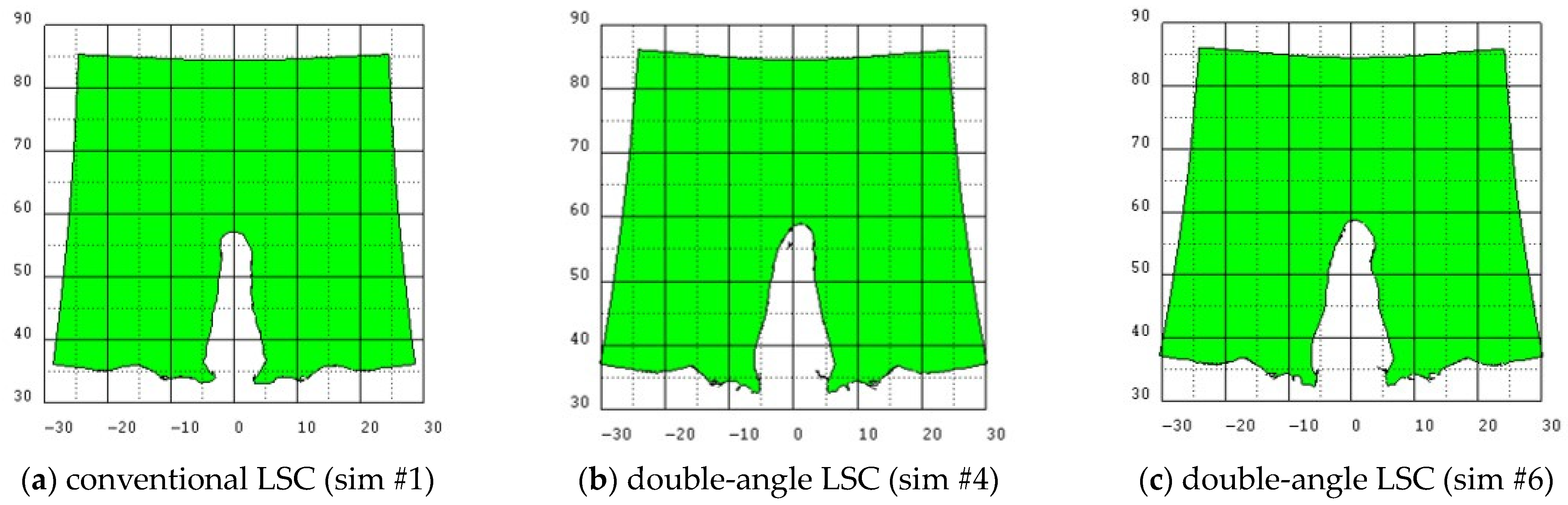
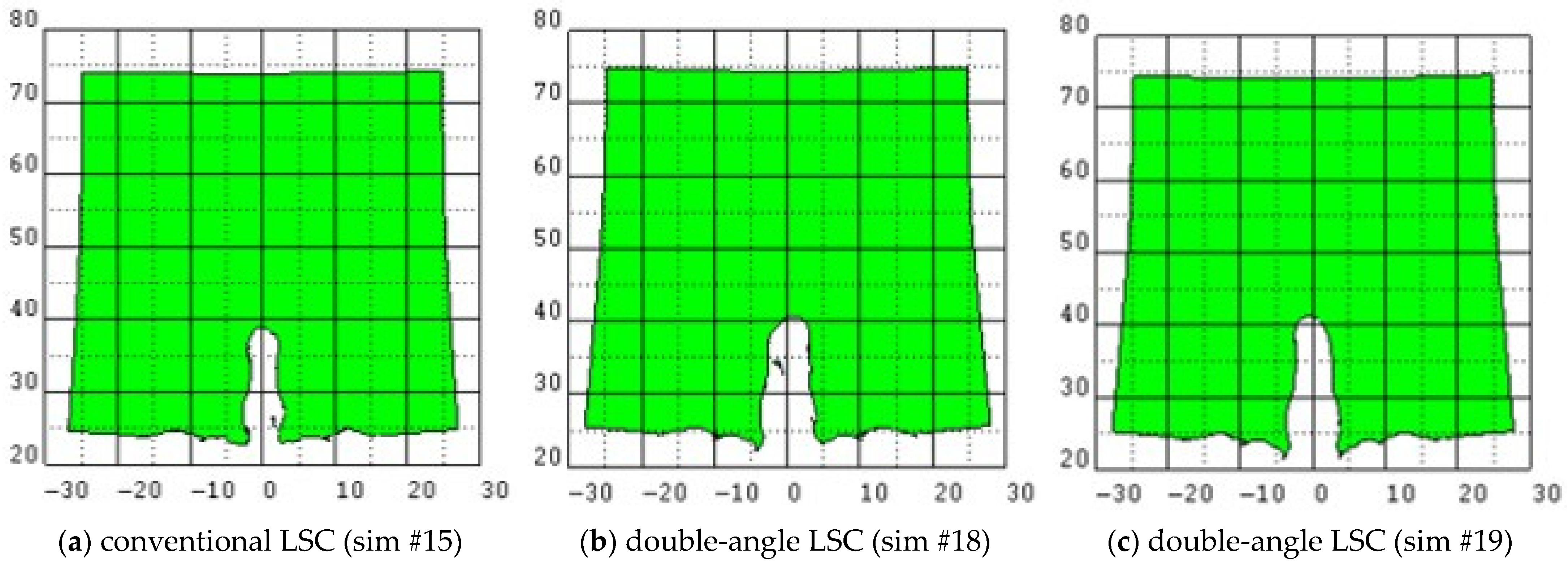
5.3. Additional Numerical Analysis and Results

Only a miniaturized linear shaped charge can be applied to stage separation devices. To miniaturize the linear shaped charge, additional numerical analysis was performed with both the explosive height and standoff distance set to 1 CD. Representative simulation models are presented in Figure 10. The numerical analysis settings were the same as those performed previously. Additional numerical analysis results are shown in Table 10, and the target shapes of the representative numerical analysis results are presented in Figure 11.
In the linear shaped charges with both the explosive height and standoff distance as 1 CD, all double-angle liner shapes had better penetration performances than the conventional liner shape. Among them, the sim #19 shape had a 14.6% better penetration performance than the conventional shape.

6. Conclusions

In this study, the penetration performance of the double-angle linear shaped charge was investigated. The double-angle liner applied in this study has a large inner apex angle and a small outer liner angle. Experiments were performed to verify the numerical analysis method, and it was confirmed that the numerical analysis results followed the experimental results well. Through numerical analysis, we determined that at the explosive height of 1.5 CD and standoff distance of 1.5 CD, the penetration performance of the double-angle linear shaped charge was 14.5% superior to that of the conventional linear shaped charge. At the explosive height of 1.5 CD and standoff distance of 2.5 CD, the performance of the new linear shaped charge was superior by 12.5%. The shape of the double-angle liner with the maximum penetration performance varies depending on the standoff distance. Therefore, optimization of the liner shape according to the conditions and environment is necessary. For miniaturization, numerical analysis was performed by reducing the explosive height and separation distance to 1 CD each, and the results showed that the penetration performance of the double-angle linear shaped charge was 14.6% better than that of the conventional linear shaped charge. Considering the previous results, it seems it is effective to apply a double-angle liner to improve the penetration performance of a linear shaped charge.

Author Contributions

Conceptualization, J.P. and S.K.; methodology, J.P. and S.K.; software, J.P.; validation, J.P. and S.K.; formal analysis, J.P.; investigation, J.P.; resources, J.P. and S.K.; data curation, J.P.; writing—original draft, J.P.; writing—review and editing, S.K.; supervision, S.K. All authors have read and agreed to the published version of the manuscript.

Funding

This research received no external funding.

Data Availability Statement

The original contributions presented in the study are included in the article, further inquiries can be directed to the corresponding author.

Conflicts of Interest

The authors declare no conflicts of interest.

References

  1. Birkhoff, G.; MacDougall, D.P.; Pugh, E.M.; Taylor, G. Explosives with Lined Cavities. J. Appl. Phys. 1948, 19, 563–582. [Google Scholar] [CrossRef]
  2. Pugh, E.M.; Eichelberger, R.J.; Rostoker, N. Theory of Jet Formation by Charges with Lined Conical Cavities. J. Appl. Phys. 1952, 23, 532–536. [Google Scholar] [CrossRef]
  3. Walters, W.P.; Zukas, J.A. Fundamentals of Shaped Charges; A Wiley-Interscience Publication: Hoboken, NJ, USA, 1989. [Google Scholar]
  4. Shekhar, H. Theoretical Modelling of Shaped Charges in the Last Two Decades (1990–2010): A Review. Cent. Eur. J. Energetic Mater. 2012, 9, 155–185. [Google Scholar]
  5. Vigil, M.G. Design of Linear Shaped Charges Using the LESCA; Sandia Report; Sandia National Laboratories: Albuquerque, NM, USA, 1990; p. SAND90-0243.
  6. Vigil, M.G. Precision Linear Shaped Charge Analyses for Severance of Metal; Sandia Report; Sandia National Laboratories: Albuquerque, NM, USA, 1996; p. SAND96-2031.
  7. Lim, S. Steady State Equation of Motion of a Linear Shaped Charges Liner. Int. J. Impact Eng. 2012, 44, 10–16. [Google Scholar] [CrossRef]
  8. Lim, S. Jet Velocity Profile of Linear Shaped Charges Based on an Arced Liner Collapse. J. Energetic Mater. 2013, 31, 239–250. [Google Scholar] [CrossRef]
  9. Lim, S. Liner Collapse Line of Linear Shaped Charges. J. Energetic Mater. 2017, 35, 125–135. [Google Scholar] [CrossRef]
  10. Lim, S.; Baldovi, P.; Rood, C. Jet Grouping of Linear-Shaped Charges and Penetration Performance. Appl. Sci. 2022, 12, 12768. [Google Scholar] [CrossRef]
  11. Li, Y.; Zhai, Z.; Fan, X.; Han, H.; Zhao, Y.; Cao, H. Orthogonal Structure Design of the Linear Shaped Charge based on Steady State Velocity Model. J. Phys. Conf. Ser. 2023, 2478, 072057. [Google Scholar] [CrossRef]
  12. Bohanek, V.; Dobrilovic, M.; Skrlec, V. The Efficiency of Linear Shaped Charges. Teh. Vjesn.—Tech. Gaz. 2014, 21, 525–531. [Google Scholar]
  13. Sterbentz, D.M.; Jekel, C.F.; White, D.A.; Rieben, R.N.; Belof, J.L. Linear Shaped Charge Jet Optimization using Machine Learning Method. J. Appl. Phys. 2023, 134, 045102. [Google Scholar] [CrossRef]
  14. Cheng, X.; Huang, G.; Liu, C.; Feng, S. Design of a Novel Linear Shaped Charge and Factors Influencing its Penetration Performance. Appl. Sci. 2018, 8, 1863. [Google Scholar] [CrossRef]
  15. Bui, X.S.; Do, V.M.; Dang, V.L. Effect of Shaped of Double-Cone Liner on Penetration Depth of Shaped Charge without Wave Shaper. J. Sci. Tech. 2021, 16, 72–84. [Google Scholar] [CrossRef]
  16. El-Sayed, E.E.; Elshenawy, T.A.; Shaker, M.A. Influence of Different Shaped Charge Parameters on Jet Penetration into Metallic Target. J. Phys. Conf. Ser. 2022, 2299, 012016. [Google Scholar] [CrossRef]
  17. Li, H.; Li, P.; Duan, H.; Zhang, Z. Study on Jet Formation and Penetration Performance of Shaped Charge with Untypical Double-cone Titanium Liner. J. Phys. Conf. Ser. 2023, 2599, 012028. [Google Scholar] [CrossRef]
  18. Gürel, E. Modeling and Simulation of Shaped Charge. Master’s Thesis, Middle East Technical University, Ankara, Turkey, 2009. [Google Scholar]
  19. Ralph, M. JWL Equation of State; Los Alamos National Laboratory: Los Alamos, NM, USA, 2017; p. LA-UR-15-29536.
  20. Baudin, G.; Serradeil, R. Review of Jones-Wilkins-Lee equation of state. In Proceedings of the EPJ Web of Conferences 10, Poitiers, France, 4–9 July 2010; p. 00021. [Google Scholar]
  21. Heuze, O. General form of the Mie-Gruneisen equation of state. C. R. Mec. 2012, 340, 679–687. [Google Scholar] [CrossRef]
  22. Zocher, M.A.; Maudlin, P.J.; Chen, S.R.; Flower-Maudlin, E.C. An Evaluation of Several Hardening Models Using Taylor Cylinder Impact Data. In Proceedings of the European Congress on Computational Methods in Applied Sciences and Engineering, Barcelona, Spain, 11–14 September 2000. [Google Scholar]
Figure 1. Schematic diagram of a (a) conventional linear shaped charge and (b) double-angle linear shaped charge. The inner apex angle (A2) and inner explosive width (C2) are variable design parameters.
Aerospace 11 00310 g001
Figure 2. Representative simulation models with 1.5 CD standoff distance: (a) material index; (b) #1 simulation model of conventional LSC: apex angle is 70°; (c) #4 simulation model of double-angle LSC: outer liner angle is 70° and inner apex angle is 110°, while inner explosive width is 0.6 CD; (d) #6 simulation model of double-angle LSC: outer liner angle is 70° and inner apex angle is 120°, while inner explosive width is 5 CD.
Aerospace 11 00310 g002
Figure 3. The double-angle linear shaped charges used in the experiments. (a) The same as the #4 simulation model: outer liner angle is 70° and inner apex angle is 110°, while inner explosive width is 0.6 CD; (b) The same as the #6 simulation model: outer liner angle is 70° and inner apex angle is 120°, while inner explosive width is 0.5 CD.
Aerospace 11 00310 g003
Figure 4. The experimental setups.
Aerospace 11 00310 g004
Figure 5. Components of the experimental setup.
Aerospace 11 00310 g005
Figure 6. Experimental result of double-angle linear shaped charge with 1.5 CD standoff. The target block is penetrated by specimen #3. The penetration depth is 2.37 CD (23.7 mm).
Aerospace 11 00310 g006
Figure 7. Experimental results of double-angle linear shaped charge with 1.5 CD standoff. The target block is penetrated by specimen #4. The penetration depth is 2.43 CD (24.3 mm).
Aerospace 11 00310 g007
Figure 8. Experimental results of double-angle linear shaped charge with 2.5 CD standoff. The target blocks were destroyed and the penetration depth could not be measured.
Aerospace 11 00310 g008
Figure 9. Representative simulation results with 1.5 CD standoff distance. The unit of the axis is mm. The target size is 50 mm × 50 mm. The penetration depth is (a) conventional LSC: 2.27 CD; (b) #4 double-angle LSC: 2.43 CD; (c) #6 double-angle LSC: 2.41 CD.
Aerospace 11 00310 g009
Figure 10. The representative simulation models with 1 CD standoff distance and 1 CD explosive height: (a) material index and location; (b) #15 simulation model of conventional LSC: apex angle is 70°; (c) #18 simulation model of double-angle LSC: outer liner angle is 70° and inner apex angle is 110°, while inner explosive width is 0.6 CD; (d) #19 simulation model of double-angle LSC: outer liner angle is 70° and inner apex angle is 120°, while inner explosive width is 0.4 CD.
Aerospace 11 00310 g010
Figure 11. The representative simulation results with 1 CD standoff distance and 1 CD explosive height. The unit of the axis is mm. The target size is 50 mm X 50 mm. The penetration depth is (a) conventional LSC: 1.51 CD; (b) #18 double-angle LSC: 1.65 CD; (c) #19 double-angle LSC: 1.73 CD.
Aerospace 11 00310 g011
Table 1. Parameters of the conventional linear shaped charge and double-angle linear shaped charge.
SimTypeA1 (º)A2 (º)CD (mm)C2 (CD)H (CD)t (mm)
#1Conventional70-10-1.51
#2
#3
#4
Double-angle70110100.4
0.5
0.6
1.51
#5
#6
#7
Double-angle70120100.4
0.5
0.6
1.51
Table 2. Material, EOS and strength model for each part.
PartMaterialEOSStrength ModelErosion
ExplosiveHMX-TNTJWL--
LinerCu-OFHCMie–Gruneisen shockSteinberg–Guinan-
CaseAl 6061 T6Mie–Gruneisen shockSteinberg–Guinan-
TargetAl 6061 T6Mie–Gruneisen shockSteinberg–GuinanInstantaneous
geometric strain
Table 3. JWL EOS parameters of HMX-TNT.
Density (g/cc)A (GPa)B (GPa) R 1 R 2 ωC-J Detonation Velocity (m/s)C-J Energy per Unit Volume (GJ/m3)C-J Pressure (GPa)
1.776700.812.124.51.100.3082108.931.1
Table 4. Mie–Gruneisen EOS parameters of Cu-OFHC and Al 6061 T6.
MaterialDensity (g/cc)Γ C 0 (m/s)S T 0 (K)Specific Heat (J/kgK)
Cu-OFHC8.9302.0239401.489300383
Al 6061 T62.7031.9752401.400300885
Table 5. Steinberg–Guinan strength model parameters of Cu-OFHC and Al 6061 T6.
MaterialShear Modulus (GPa)Yield Stress (GPa)Maximum Yield Stress (GPa)Hardening
Constant
Melting
Temperature (K)
Cu-OFHC47.700.120.64361790
Al 6061 T627.600.290.681251220
Table 6. Dimensions of the double-angle linear shaped charge used in the experiment.
SpecimenSimulationA1 (º)A2 (º)CD (mm)C2 (CD)H (CD)t (mm)Standoff (CD)
#3#4
#11
70110100.61.511.5
2.5
#4#6
#13
70120100.51.511.5
2.5
Table 7. Penetration depths of experiments.
DALSC #A1 (º)A2 (º)C2 (CD)Standoff
(CD)
Penetration
Depth (CD)
#3701100.61.52.37
#4701200.51.52.43
Table 8. Comparison of numerical analysis results and experimental results.
SpecimenTypeStandoff (mm)Simulation (mm)Experiment (mm)Sim-Exp (mm)Err (%)
#3DALSC1524.323.70.62.5
#4DALSC1524.124.3−0.2−0.8
Table 9. Numerical analysis results. The reference increase rate is the penetration depth of the conventional LSC.
SimSpecimenTypeA1 (º)A2 (º)C2 (CD)Standoff (CD)Penetration Depth (Sim) (CD)Increase Rate
(%)
#1 LSC70--1.52.27-
#2 DALSC701100.41.52.5813.7
#3 DALSC701100.51.52.6014.5
#4#3DALSC701100.61.52.437.0
#5 DALSC701200.41.52.5713.2
#6#4DALSC701200.51.52.416.2
#7 DALSC701200.61.52.322.2
#8 LSC70--2.52.48-
#9 DALSC701100.42.52.708.9
#10 DALSC701100.52.52.594.4
#11#3DALSC701100.62.52.594.4
#12 DALSC701200.42.52.7912.5
#13#4DALSC701200.52.52.604.8
#14 DALSC701200.62.52.45−1.2
Table 10. Additional numerical analysis results for short height and short standoff distance.
Sim #TypeA1 (º)A2 (º)C2 (CD)H(CD)Standoff (CD)Penetration
(CD)
Increase Rate
(%)
#15LSC70--111.51-
#16DALSC701100.4111.542.0
#17DALSC701100.5111.659.3
#18DALSC701100.6111.659.3
#19DALSC701200.4111.7314.6
#20DALSC701200.5111.648.6
#21DALSC701200.6111.574.0
Disclaimer/Publisher’s Note: The statements, opinions and data contained in all publications are solely those of the individual author(s) and contributor(s) and not of MDPI and/or the editor(s). MDPI and/or the editor(s) disclaim responsibility for any injury to people or property resulting from any ideas, methods, instructions or products referred to in the content.

