
Variable Switching System for Heat Protection and Dissipation of Ultra-LEO Satellites Based on LHP Coupled with TEC


Abstract
1. Introduction
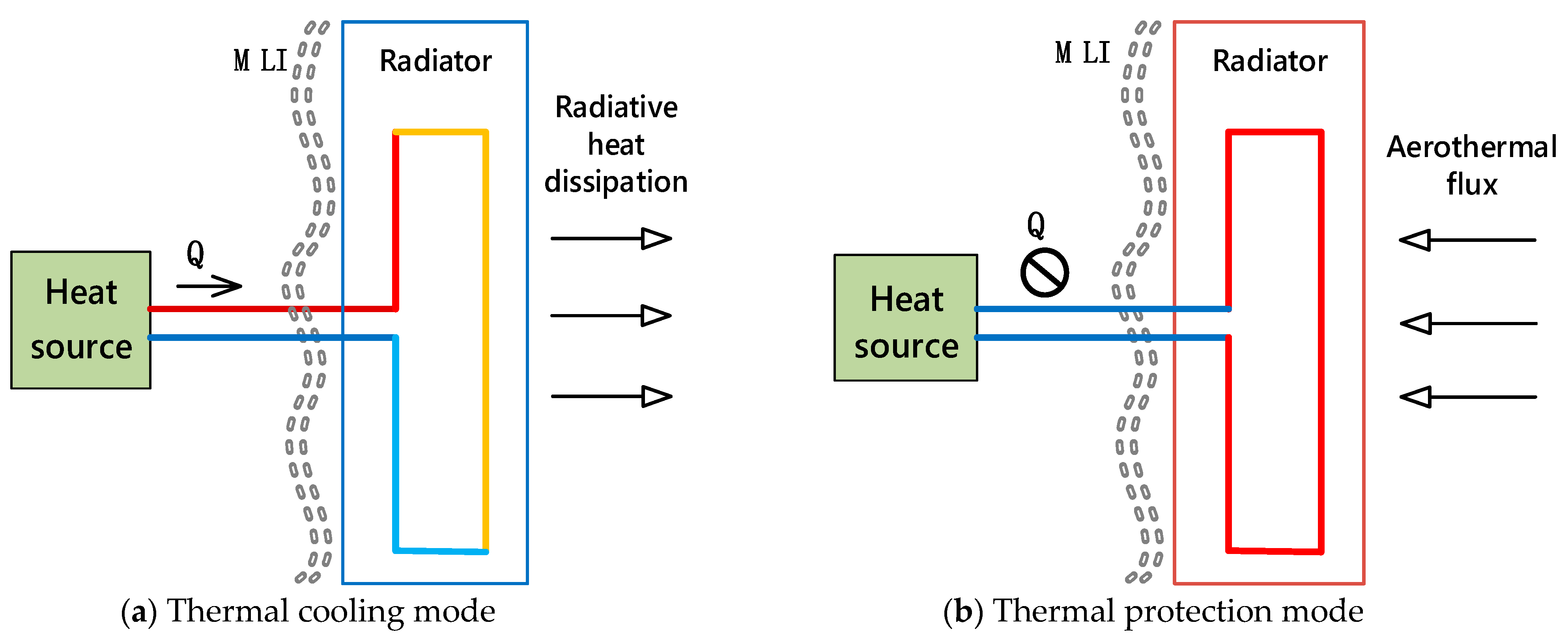
2. System Scheme
2.1. Design of Variable Heat Dissipation System
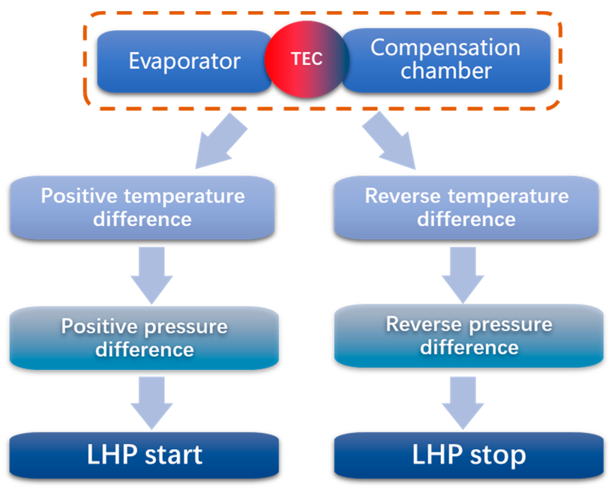
2.2. Design of TEC Control
3. Mission Flow and Aerothermal Flux Calculation
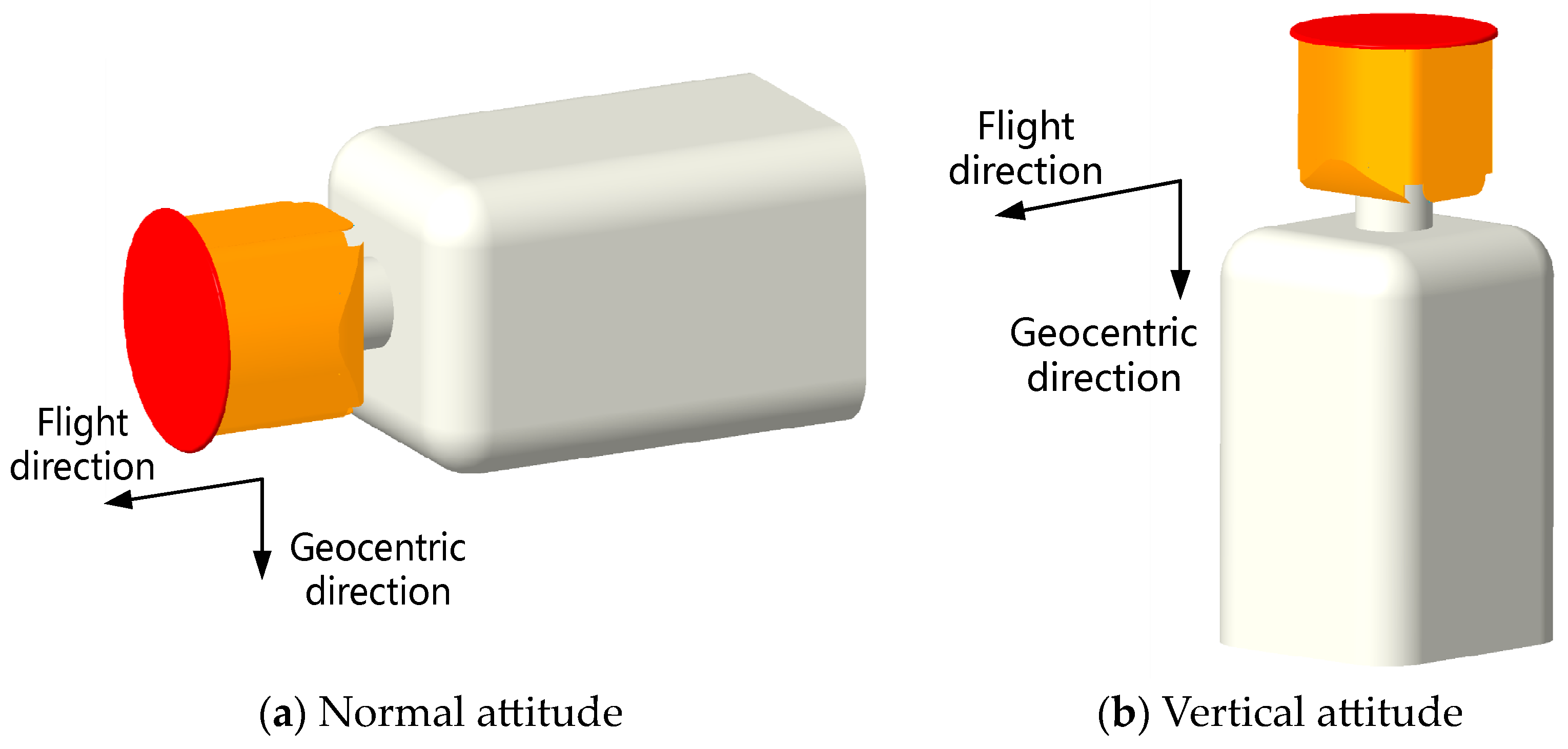
3.1. Introduction of Mission Flow
3.2. Calculation of Aerothermal Flux
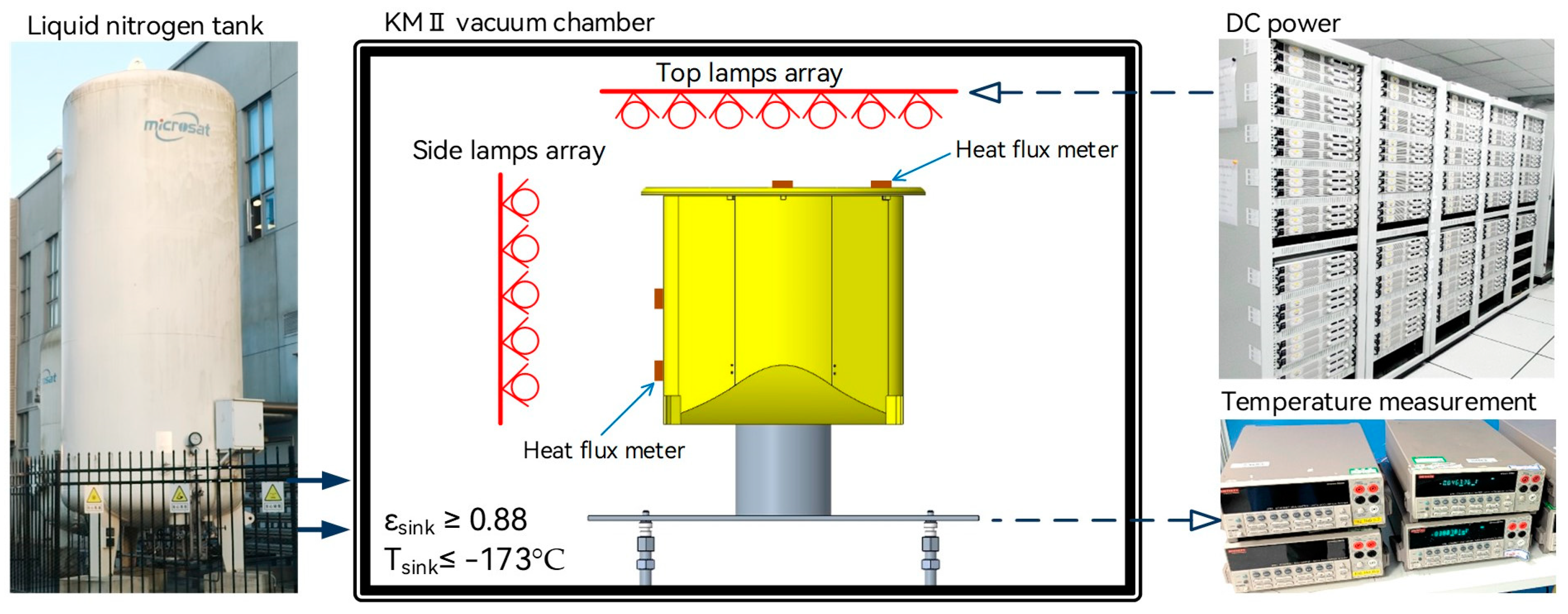
4. Experimental Setup
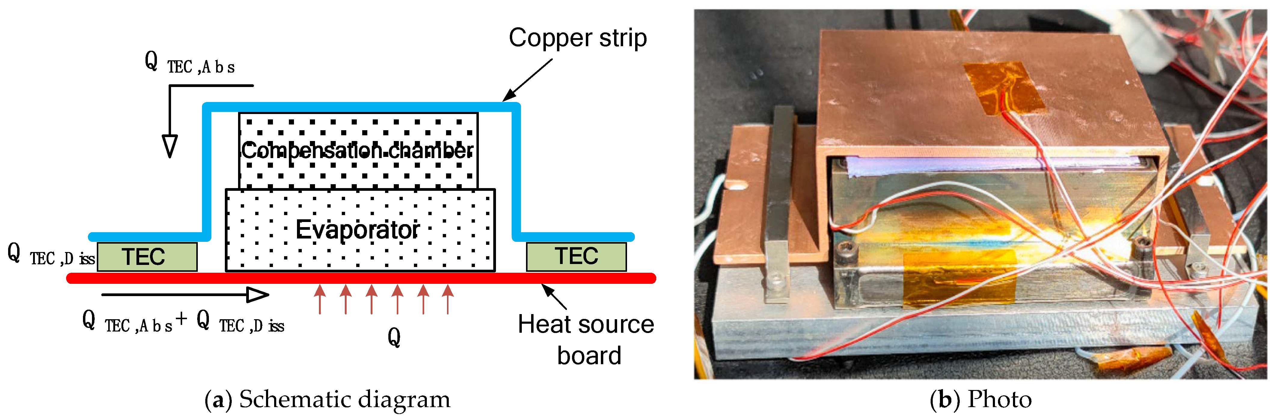
4.1. LHP Coupled with TEC
4.2. Aerothermal Flux Loading
4.3. Test Methods
5. Experiments and Results
5.1. Effect of TEC Power on System Temperature
5.2. Heat Protection and Temperature Tolerance Test
5.3. LHP Startup Response and Cooling Test
5.4. Whole Process Thermal Test of the Ultra-LEO Mission
6. Conclusions
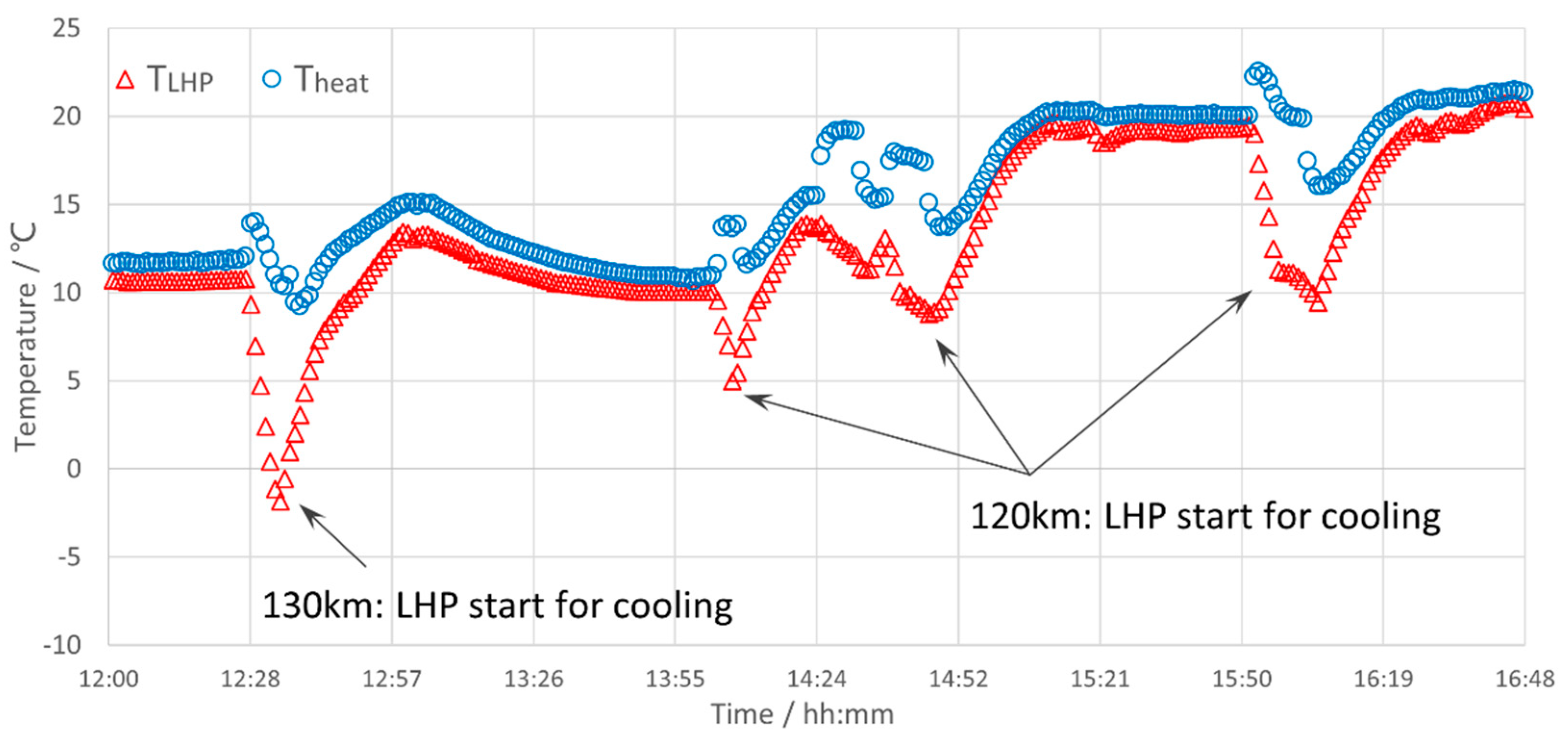
- When the orbital altitude is below 160 km, the surface of the satellite will produce non-negligible aerothermal flux. When the orbital altitude is 120 km, the aerothermal flux on the windward side of the satellite will reach 5100 W/m2.
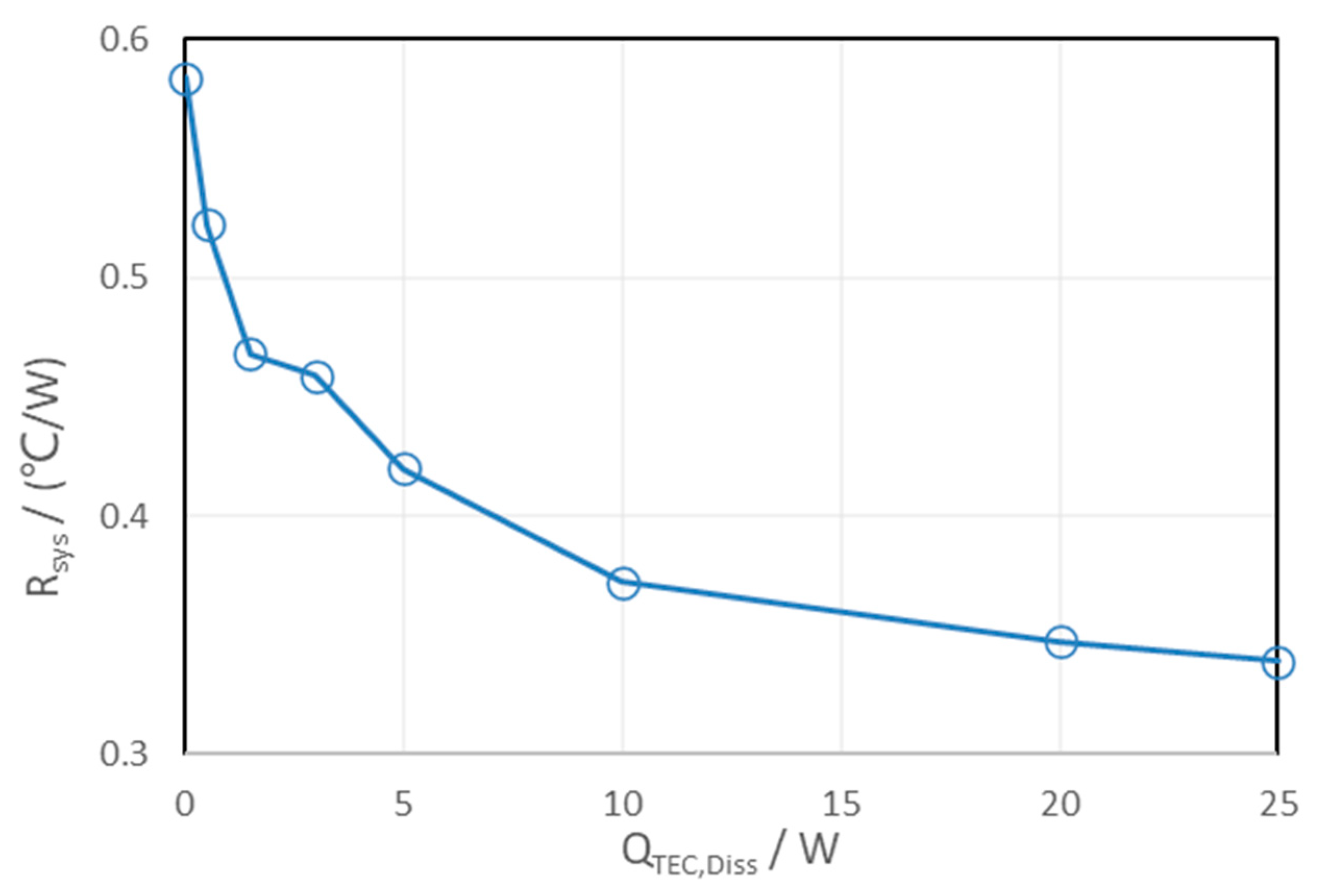
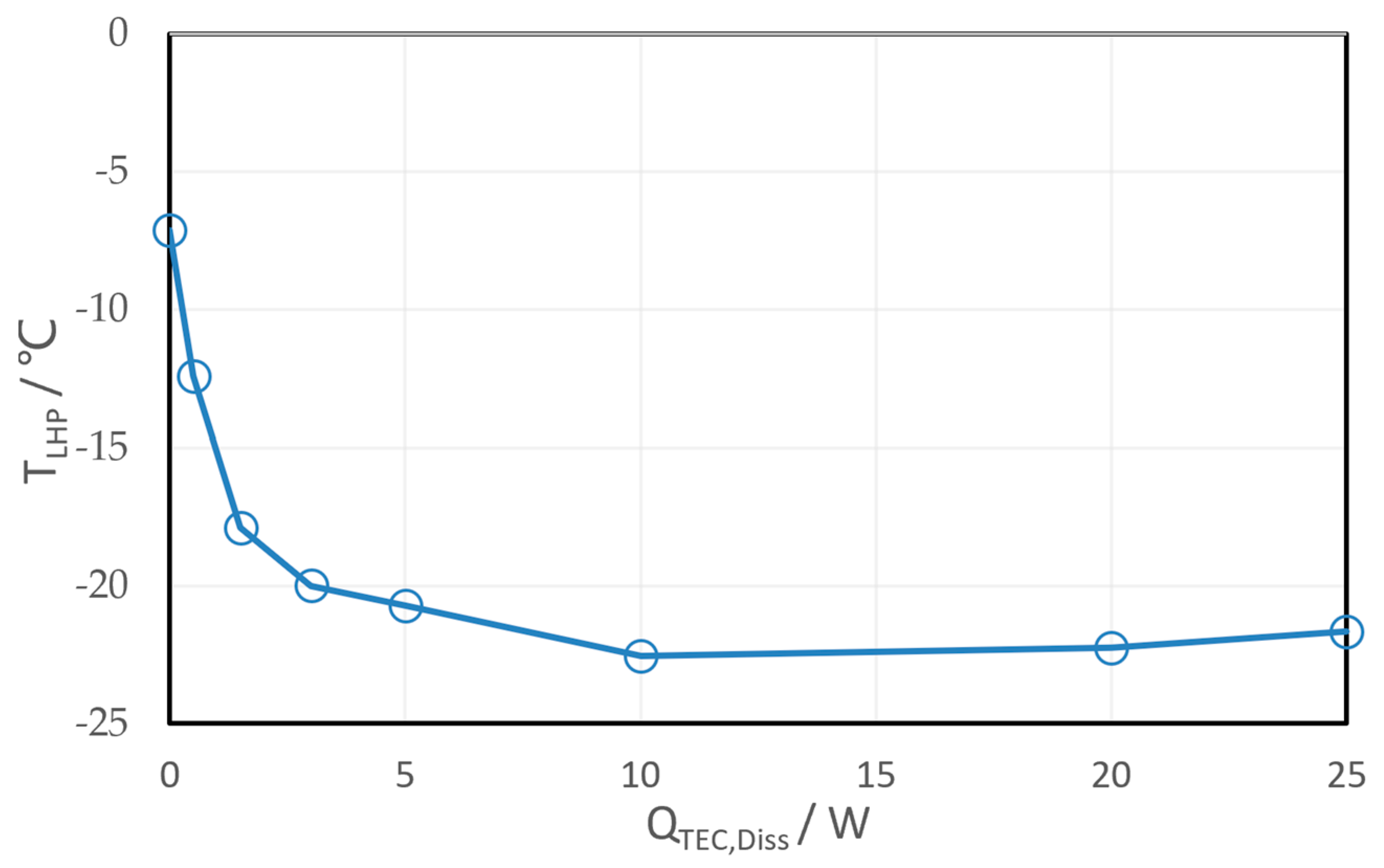
- TEC low power supply can greatly enhance the cooling effect of the system. At a TEC power supply power of 10 W, the system operating temperature dropped to its lowest—if the TEC power further increased, the system temperature began to gradually rise.
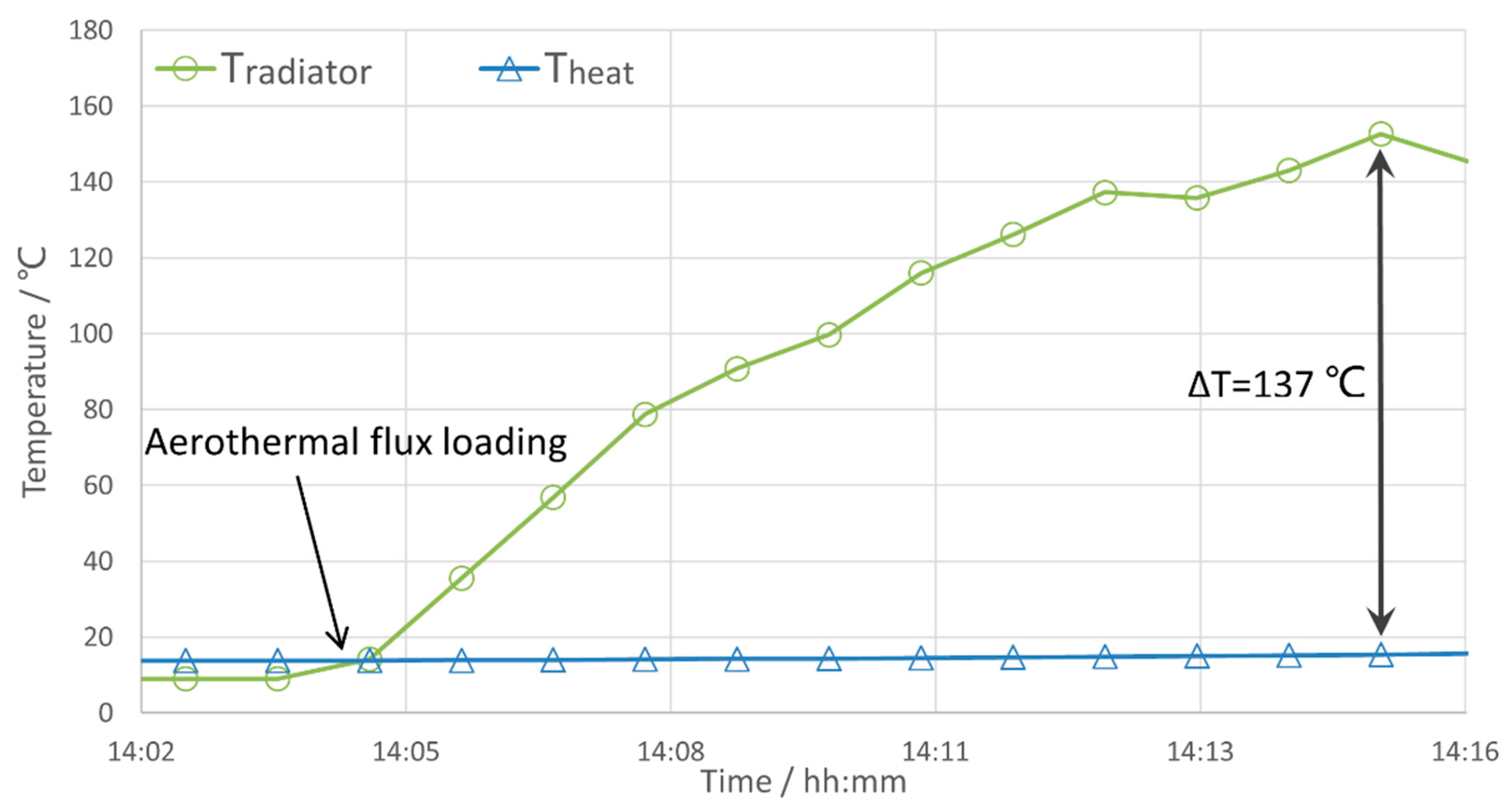
- The heat protection test showed that when the temperature difference between the external radiator and the internal temperature was as high as 137 °C, the internal temperature of the system showed only a small rise of 1.5 °C, so the system has a good heat protection effect.
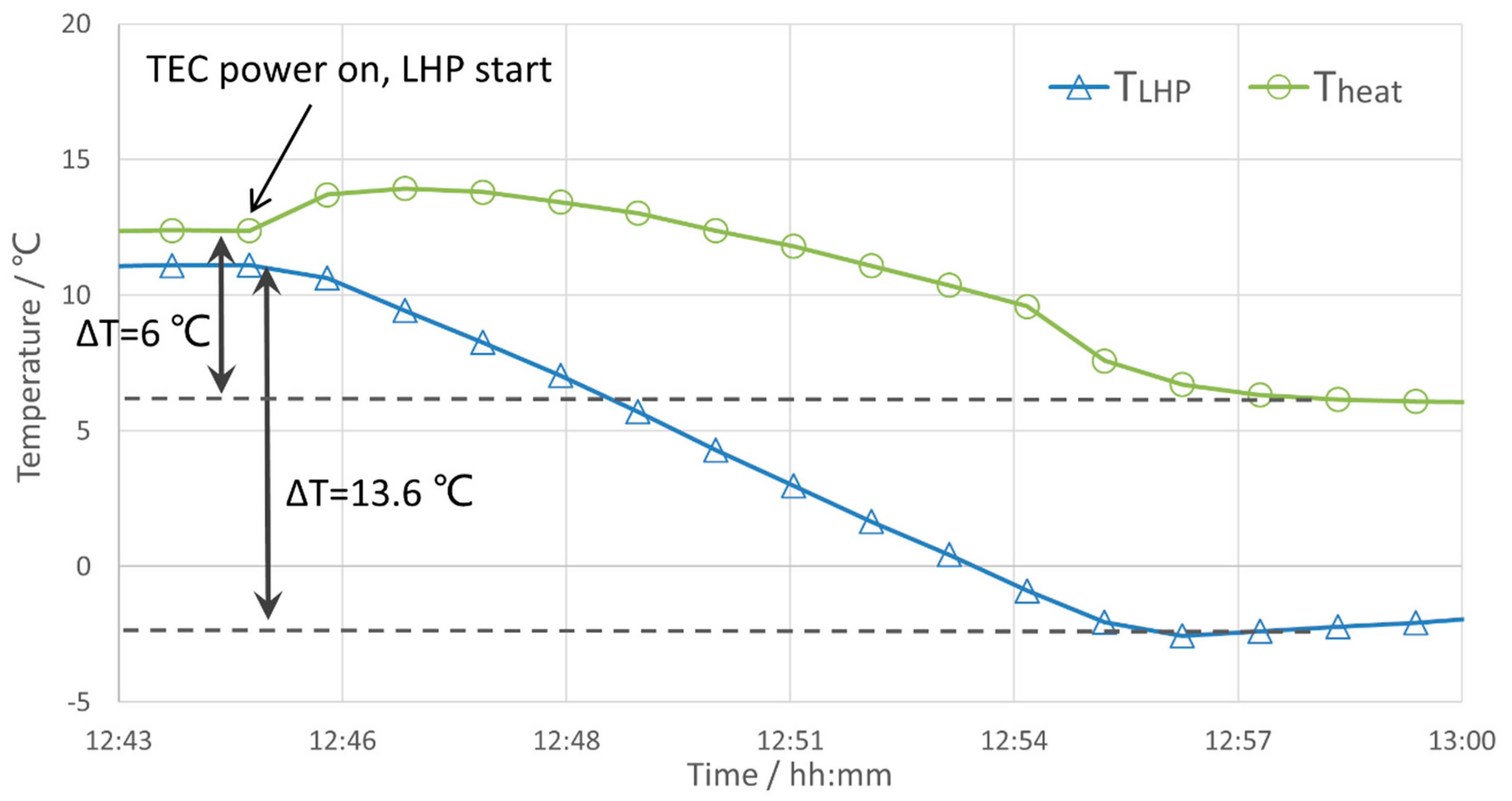
- The LHP coupled with the TEC can start quickly within 1.5 min. The LHP operating temperature can be reduced by 13.6 °C within only 10 min, and the temperature of the heat source inside the system can be reduced by about 6 °C.
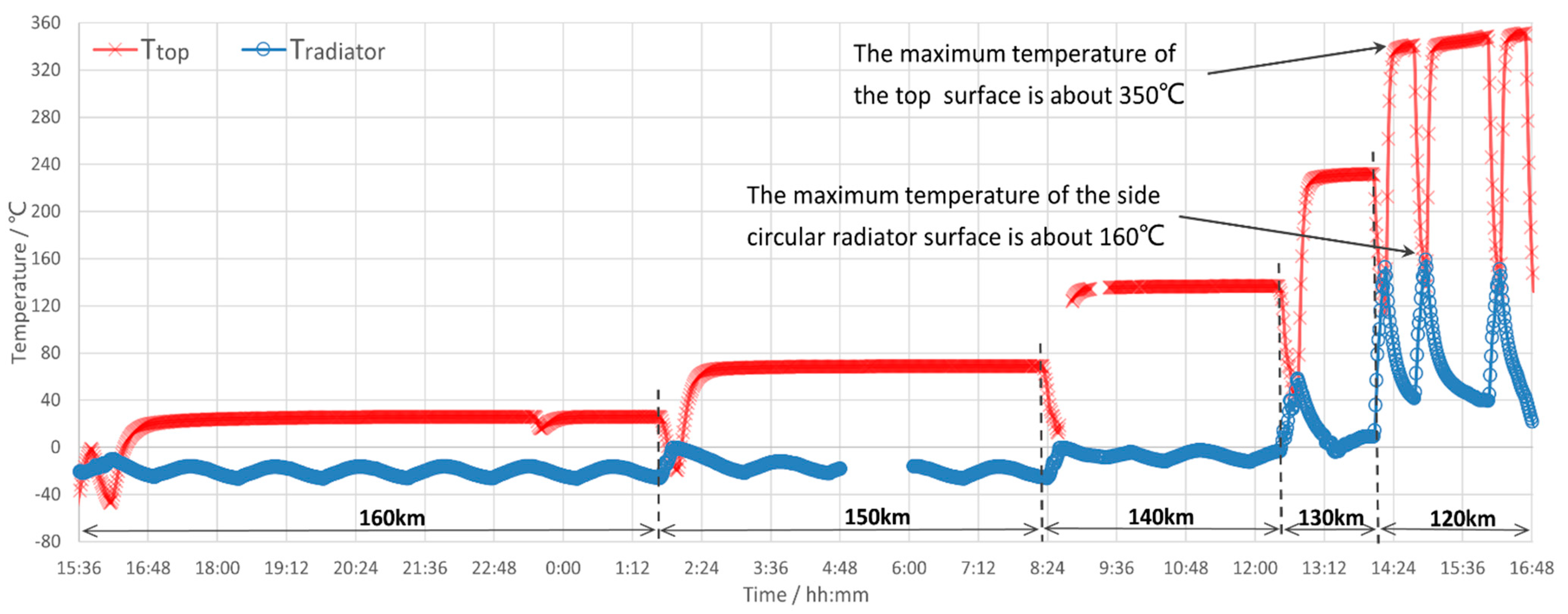
- The system has passed the assessment of the whole aerothermal test process even if the top temperature rose to 350 °C and the temperature of the side radiator rose to 160 °C, the temperature of the internal heat source can be controlled within 22.5 °C through the efficient work of the variable switch system for heat protection and dissipation.
Author Contributions
Funding
Data Availability Statement
Conflicts of Interest
Nomenclature
| k | Boltzman’s Constant, J/K | |
| M | Mach Number | |
| N | Number of molecules per unit volume, mol/m3 | |
| n | Number of molecules striking unit surface area per unit time, mol/(m2.s) | |
| P | Pressure, Pa | |
| q | Heating flux, W/m2 | |
| Q | Heat load, W | |
| R | Thermal resistance, K/W | |
| S | Molecular speed ratio | |
| T | Temperature, °C | |
| v | Velocity, m/s | |
| CC | Compensation chamber | |
| LHP | Loop heat pipe | |
| ρ | Density | |
| γ | Specific heat ratio | |
| α | Coefficient accommodation | |
| θ | Angle of incidence, ° | |
| Subscripts | ||
| ∞ | Free-stream | |
| e | Evaporator | |
| w | Wall | |
| heat | Heat source equipment | |
| sink | Heat sink | |
References
- Crisp, N.H.; Roberts, P.C.E.; Livadiotti, S.; Oiko, V.; Edmondson, S.; Haigh, S.; Huyton, C.; Sinpetru, L.; Smith, K.; Worrall, S.; et al. The benefits of very low earth orbit for earth observation missions. Prog. Aerosp. Sci. 2020, 117, 100619. [Google Scholar] [CrossRef]
- Llop, J.V.; Roberts, P.C.; Hao, Z.; Tomas, L.R.; Beauplet, V. Very low earth orbit mission concepts for earth observation: Benefits and challenges. In Proceedings of the 12th Reinventing Space Conference, London, UK, 18–20 November 2014; pp. 18–21. [Google Scholar]
- Najafabadi, M.A.; Kazemi, I. Systemic design of the very-high-resolution imaging payload of an optical remote sensing satellite for launch into the VLEO using an small launch vehicle. Heliyon 2024, 10, e27404. [Google Scholar] [CrossRef] [PubMed]
- Crisp, N.H.; Roberts, P.C.E.; Romano, F.; Smith, K.; Oiko, V.; Sulliotti-Linner, V.; Hanessian, V.; Herdrich, G.; García-Almiñana, D.; Kataria, D.; et al. System modelling of very low Earth orbit satellites for Earth observation. Acta Astronaut. 2021, 187, 475–491. [Google Scholar] [CrossRef]
- Zhang, X.; Zhu, Z.; Chen, H. Aerodynamic passive stabilization design and flight data analyses for transitional regime satellite LX-1. Acta Astronaut. 2020, 167, 232–238. [Google Scholar]
- Kimoto, Y.; Yukumatsu, K.; Goto, A.; Miyazaki, E.; Tsuchiya, Y. MDM: A flight mission to observe materials degradation in-situ on satellite in super low Earth orbit. Acta Astronaut. 2021, 179, 695–701. [Google Scholar] [CrossRef]
- Votta, R.; Schettino, A.; Bonfiglioli, A. Hypersonic high altitude aerothermodynamics of a space re-entry vehicle. Aerosp. Sci. Technol. 2013, 25, 253–265. [Google Scholar] [CrossRef]
- Marshall, L.; Corpening, G.; Sherrill, R. A chief engineer’s view of the NASA X-43A scramjet flight test. In Proceedings of the AIAA/CIRA 13th International Space Planes and Hypersonics Systems and Technologies Conference 2005, Capua, Italy, 16–20 May 2005; p. 3332. [Google Scholar]
- Uyanna, O.; Najafi, H. Thermal protection systems for space vehicles: A review on technology development, current challenges and future prospects. Acta Astronaut. 2020, 176, 341–356. [Google Scholar] [CrossRef]
- Tian, Y.; Zhang, X.; Dou, S.; Zhang, L.; Zhang, H.; Lv, H.; Wang, L.; Zhao, J.; Li, Y. A comprehensive study of electrochromic device with variable infrared emissivity based on polyaniline conducting polymer. Sol. Energy Mater. Sol. Cells 2017, 170, 120–126. [Google Scholar] [CrossRef]
- Granqvist, C.G.; Hultåker, A. Transparent and conducting ITO films: New developments and applications. Thin Solid Film. 2002, 411, 1–5. [Google Scholar] [CrossRef]
- Darrin, A.G.; Osiander, R.; Champion, J.; Swanson, T.; Douglas, D.; Grob, L. Variable emissivity through MEMS technology. Space Technol. Appl. Int. Forum 2000, 504, 803. [Google Scholar]
- Matovic, J.; Vujanic, A.; Reichenberger, K. Variable Emissivity Surfaces for Micro and Nanosatellites. CANEUS MNT Aerosp. Appl. 2006, 42541, 135–140. [Google Scholar]
- Nagano, H.; Ohnishi, A.; Nagasaka, Y. Development of a lightweight deployable/stowable radiator for interplanetary exploration. Appl. Therm. Eng. 2011, 31, 3322–3331. [Google Scholar] [CrossRef]
- Nagano, H.; Nagasaka, Y.; Ohnishi, A. Simple deployable radiator with autonomous thermal control function. J. Thermophys. Heat Transf. 2006, 20, 856–864. [Google Scholar] [CrossRef]
- Maydanik, Y.F. Loop heat pipes. Appl. Therm. Eng. 2005, 25, 635–657. [Google Scholar] [CrossRef]
- Mitomi, M.; Nagano, H. Long-distance loop heat pipe for effective utilization of energy. Int. J. Heat Mass Transf. 2014, 77, 777–784. [Google Scholar] [CrossRef]
- Franzoso, A.; Tjiptahardja, T.; Ruzza, P.; Vettore, C. TECLA: A TEC-enhanced Loop Heat Pipe. In Proceedings of the 43rd International Conference on Environmental Systems, Vail, CO, USA, 14–18 July 2013. [Google Scholar]
- Fang, Z.; Xie, Y.; Xu, Y.; Wu, H.; Zhang, H.; Han, L. Performance investigation of a loop heat pipe integrated with thermo-electric cooler under acceleration field. Int. J. Heat Mass Transf. 2021, 178, 121476. [Google Scholar] [CrossRef]
- Tsien, H.S. Superaerodynamics, mechanics of rarefied gases. J. Aeronaut. Sci. 1946, 13, 653–664. [Google Scholar] [CrossRef]
- Engel, C.D.; Praharaj, S.C. MINIVER Upgrade for the AVID System. Volume 1: LANMIN User’s Manual; NASA Contractor Report 172212; NASA: Greenbel, MD, USA, 1983. [Google Scholar]
- Oppenheim Antoni, K. Generalized theory of convective heat transfer in a free-molecule flow. J. Aeronaut. Sci. 1953, 20, 49–58. [Google Scholar] [CrossRef]


| Orbit Altitude | Mission Statement | Vertical Flight Time | Internal Payload Heat Dissipation |
|---|---|---|---|
| 160–130 km | One task per 10 km reduction | 20 min | 90 W |
| 120 km | Three vertical attitude tasks | 12 min | 90 W |
| Orbit Altitude | Atmospheric Density (kg/m3) | Aerothermal Flux in Various Regions (W/m2) | ||
|---|---|---|---|---|
| θ = 90° | θ = 30° | θ = 0° | ||
| More than 200 km | Aerothermal Flux Need Not Be Considered | |||
| 160 km | 1.23 × 10⁻⁹ | 300 | 33 | 7.7 |
| 150 km | 2.07 × 10⁻⁹ | 500 | 55 | 13 |
| 140 km | 3.83 × 10⁻⁹ | 910 | 100 | 22 |
| 135 km | 5.07 × 10⁻⁹ | 1300 | 140 | 29 |
| 130 km | 8.15 × 10⁻⁹ | 1900 | 210 | 42 |
| 120 km | 2.22 × 10⁻⁸ | 5100 | 560 | 110 |
| 110 km | 9.70 × 10⁻⁸ | 21,000 | 2300 | 460 |
Disclaimer/Publisher’s Note: The statements, opinions and data contained in all publications are solely those of the individual author(s) and contributor(s) and not of MDPI and/or the editor(s). MDPI and/or the editor(s) disclaim responsibility for any injury to people or property resulting from any ideas, methods, instructions or products referred to in the content. |
© 2024 by the authors. Licensee MDPI, Basel, Switzerland. This article is an open access article distributed under the terms and conditions of the Creative Commons Attribution (CC BY) license (https://creativecommons.org/licenses/by/4.0/).
Share and Cite
Huang, J.; Chang, L.; Dong, B.; Wang, J.; Huang, H. Variable Switching System for Heat Protection and Dissipation of Ultra-LEO Satellites Based on LHP Coupled with TEC. Aerospace 2024, 11, 539. https://doi.org/10.3390/aerospace11070539
Huang J, Chang L, Dong B, Wang J, Huang H. Variable Switching System for Heat Protection and Dissipation of Ultra-LEO Satellites Based on LHP Coupled with TEC. Aerospace. 2024; 11(7):539. https://doi.org/10.3390/aerospace11070539
Chicago/Turabian StyleHuang, Jin, Liang Chang, Baiyang Dong, Jianping Wang, and Hulin Huang. 2024. "Variable Switching System for Heat Protection and Dissipation of Ultra-LEO Satellites Based on LHP Coupled with TEC" Aerospace 11, no. 7: 539. https://doi.org/10.3390/aerospace11070539
APA StyleHuang, J., Chang, L., Dong, B., Wang, J., & Huang, H. (2024). Variable Switching System for Heat Protection and Dissipation of Ultra-LEO Satellites Based on LHP Coupled with TEC. Aerospace, 11(7), 539. https://doi.org/10.3390/aerospace11070539