Abstract
This study investigates the evaporation and ignition characteristics of a single droplet of ammonium dinitramide (ADN)-based liquid propellant utilizing a waveguide resonant cavity device, in conjunction with a high-speed photographic imaging system and testing system. Experimental methods are employed to analyze the impact of microwave pulse width and duty cycle on the puffing and meicro-explosion phenomena of the droplet, as well as the delay time and duration of ignition. The experimental findings reveal that increasing the duty cycle enhances the ignition success rate and diminishes flame development time. Specifically, elevating the microwave duty cycle from 60% to 80% reduces the ignition delay time of the droplet from 132.8 ms to 88.1 ms, and the ignition duration from 23.1 ms to 19.9 ms. Furthermore, an increase in microwave energy pulse width expedites the combustion process of the flame and influences plasma generation. Increasing the pulse width of microwave energy from 20 µs to 40 µs prolongs the ignition delay time from 140.3 ms to 200.5 ms and extends the ignition duration from 56.7 ms to 77.8 ms. Additionally, it is observed that a higher duty cycle leads to a more pronounced puffing phenomenon that initiates earlier. In contrast, a higher pulse width results in a more pronounced puffing phenomenon that commences later. This study provides a thorough investigation into the microwave ignition mechanism of ADN-based liquid propellants, offering theoretical insights into the ignition and combustion stability of such propellants in microwave-assisted ignition systems.
1. Introduction
In recent years, seeking novel propellant alternatives characterized by environmental friendliness, cost-effectiveness, and reliability has marked a significant trajectory in aerospace development [1]. The conventional use of hydrazine propellants has been prevalent owing to their commendable attributes such as high density and energy content [2]. However, these traditional hydrazine-based propellants exhibit drawbacks including low specific impulse, operational intricacies [3], hazardous health and environmental implications, flammability, and explosiveness, and may release harmful gases and contaminate the environment. In contrast, ADN propellants offer a promising alternative with low operational risks, shortened preparation cycles, and the generation of harmful polluting gases is relatively low [4,5]. Notably, ADN propellants boast advantages such as reduced toxicity, heightened specific impulse, environmental benignity, and convenient storage [6]. In 2010, Sweden launched the PRISMA technology test satellite, providing strong support for the research of subsequent propulsion systems. ADN-based thrusters achieved their first on-orbit operation, which is hailed as the greatest progress in the history of chemical propulsion technology since the invention of the first hydrazine thruster 40 years ago [7]. Scientists positioning them as prospective replacements for traditional propellants in forthcoming applications.
Currently, a significant number of ADN space thrusters undergoing extensive ground testing and in-orbit validation have adopted the catalytic ignition method [8,9,10,11]. However, this method entails demanding prerequisites such as elevated gas pressure, specialized catalytic bed materials, and preheating temperatures [12]. Moreover, challenges arise from issues like catalyst particle deactivation, sintering, and the inability to achieve cold starts within high-temperature operational environments [13]. Alternative approaches have been explored, such as the utilization of resistive heating by Andreasson et al. for propellant ignition [14], and the adoption of a torch igniter by Negri et al. to facilitate propellant ignition in hot atmospheres [15].
Microwave ignition, emerging as a promising and safe ignition method in aerospace propulsion, holds vast potential for development and has garnered considerable attention from researchers worldwide. Hirsch et al. found that microwave radiation-induced ignition markedly enhances gasoline combustion velocity compared to traditional ignition methods, thereby fostering improvements in cycle stability, combustion speed, and efficiency [16]. During microwave ignition, the excitation of a high-intensity electric field generates abundant plasma, which, through thermal, kinetic, and transport pathways, synergistically enhances combustion effectiveness [17]. Joonsik Hwang et al. investigated microwave-assisted plasma ignition in a constant volume combustion chamber (CVCC) and observed substantial acceleration in combustion compared to conventional spark ignition. They noted significant lean limit extension, pronounced flame development acceleration, and a 20% increase in flame speed with microwave-assisted plasma ignition [18]. Defilippo et al. identified a critical threshold in microwave impact on combustion; beyond this point, increasing microwave pulse width ceased to yield discernible benefits in energy input [19]. Wolk et al. explored the effects of microwave-assisted ignition on methane-air laminar flame development, observing a 10% extension of the rarefied combustion limit in constant-volume combustion chamber tests [20].
This research highlights the diverse advantages of microwave-assisted ignition in aerospace propulsion, providing insights into combustion enhancement mechanisms and optimization strategies. By leveraging microwave radiation-induced plasma and electric field effects, significant improvements in combustion efficiency, flame development, and extension of lean combustion limits can be achieved. Furthermore, the critical threshold observed in microwave impact on combustion highlights the importance of pulse width optimization for sustained effectiveness. These findings pave the way for advanced ignition technologies that not only improve the performance of propulsion systems but also promote environmental sustainability by improving combustion efficiency and reducing emissions.
Moreover, studies on droplet oscillation phenomena illuminate the complex interactions among electric fields, pressure differentials, and droplet evaporation dynamics. Understanding these phenomena enables precise control and optimization of droplet combustion processes, paving the way to enhance combustion stability and efficiency in various aerospace applications. Overall, the collective research efforts outlined here emphasize the revolutionary potential of microwave-assisted ignition in advancing aerospace propulsion technologies toward safer, more efficient, and environmentally sustainable solutions.
Furthermore, extensive research has been conducted on the impact of microwave pulse characteristics, including pulse width and duty cycle, on the combustion processes and ignition characteristics, elucidating their interrelated dynamics within the framework of microwave ignition of single droplet tests.
Z. Wang et al. investigated the impact of various pulsed microwave signals on ignition and combustion processes within a constant-capacitance combustion chamber. Their study revealed that average power significantly affects the initiation and subsequent development of microwave discharge. Moreover, pulse width emerged as a crucial factor in sustaining plasma combustion. Interestingly, under constant total applied power, microwave pulses with shorter widths demonstrated the ability to forestall non-equilibrium plasma generation by prolonging heating durations, thereby enhancing the stability of microwave-assisted combustion and expanding the dilute combustion limit [21].
In a separate study, Hemawan et al. from Michigan State University investigated microwave plasma-enhanced premixed flames. They observed a sharp increase in discharge power density with rising microwave power input, leading to an increase in discharge size. However, further increments in microwave input power resulted in decreased power density. Their research highlighted the role of microwave plasma in improving flame stability and broadening the combustible limit of rarefied combustion [22].
In 2009, Hemawan et al. delved into the coupling between microwaves and flames utilizing a tunable and compact quasi-waveguide combustion chamber resonator (QWCCR) with a tapered inner conductor. Through quantitative analyses of microwave power, gas flow rate, flame volume, equivalence ratio, and spectral intensity, they concluded that microwaves have the potential to augment flame length and intensity, widen the thin combustion flammability limit, and increase the abundance of various radicals [23].
According to a recent study, as internal nucleation and bubble growth mechanisms proceed, gas-phase alcohols within the bubbles are released from bubbles while the droplets continue heating, leading to a gradual decrease in methanol content. Simultaneously, the water component within the droplets reaches its boiling point, initiating evaporation and bubble formation. With each expansion, a portion of sub-droplets is ejected, causing the mother droplet to lose mass [24].
However, research on the ignition and combustion behavior of ADN-based liquid propellants within a microwave environment remains currently limited, particularly regarding how variations in microwave pulse width and duty cycle affect ADN combustion characteristics. There is a lack of comprehensive investigation and experimental validation in this area. To fill this gap, we have developed a liquid droplet microwave ignition test platform. This setup incorporates a rectangular waveguide resonant cavity device and a high-speed camera, enabling us to experimentally analyze the effects of changes in microwave pulse width and duty cycle on droplet morphology and the dynamics of flame development. Using the hanging droplet ignition method, our experiments aim to provide empirical insights into the complex interaction between microwave parameters and the combustion behavior of ADN-based liquid propellants.
2. Materials and Methods
2.1. Materials
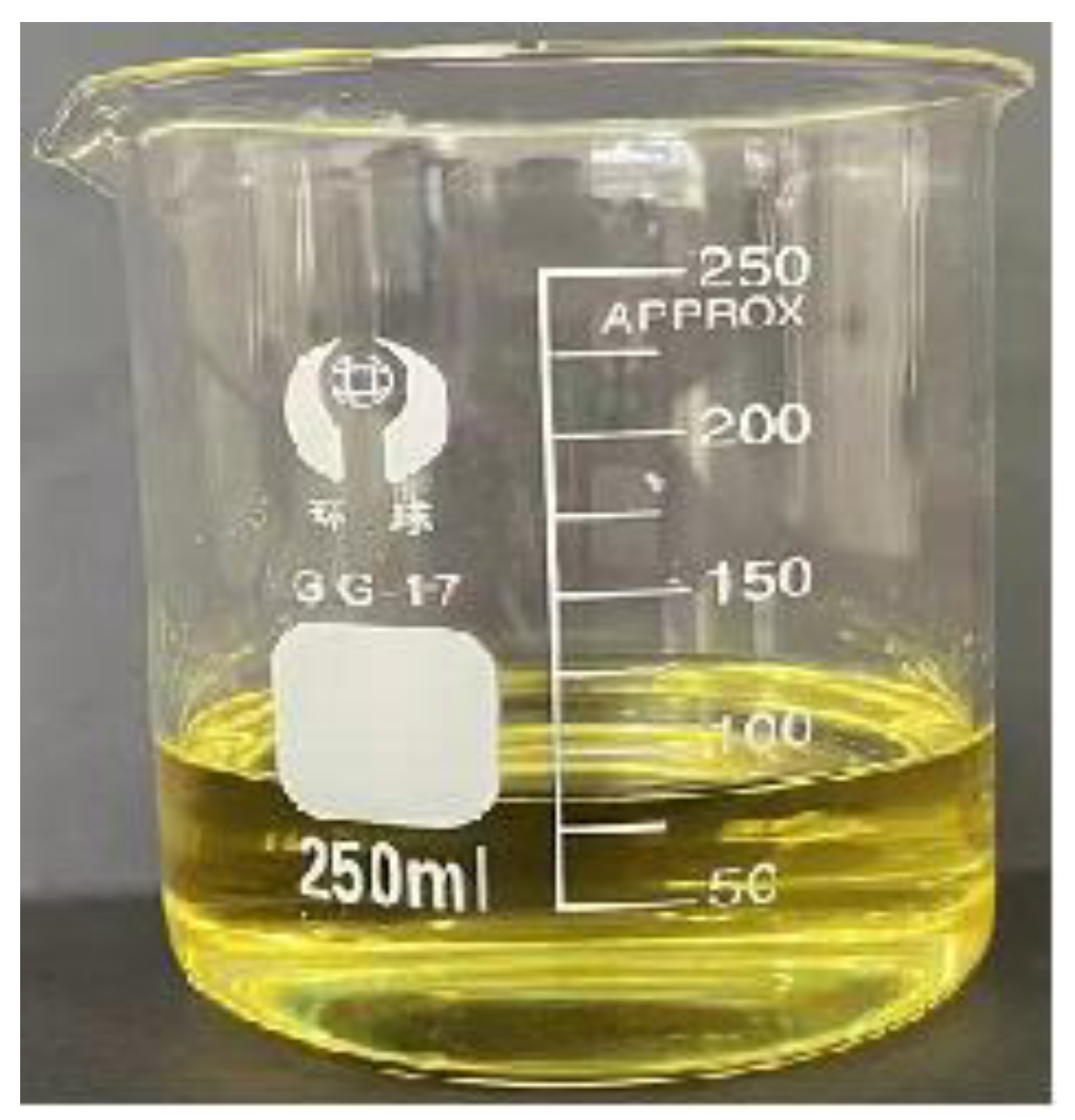
ADN is a high-energy-density material that typically appears as a white or yellowish solid under standard room temperature and pressure conditions. It comprises an amino cation paired with a dinitramide anion. Researchers have leveraged ADN’s high solubility in water to develop formulations combining ADN, water, and fuel in specific ratios. The ADN-based liquid propellant formulation employed in this study consists of 62% ADN, 26% water, and 12% methanol. Figure 1 illustrates the ADN liquid propellant utilized in our experimentation.

Figure 1.
ADN-based liquid propellant.
2.2. Test Devices and Methods
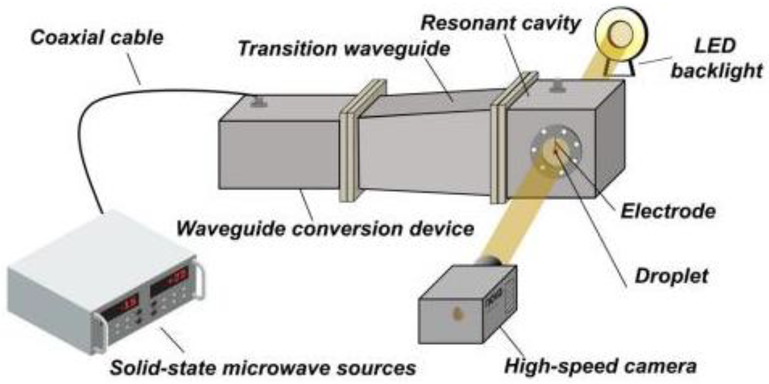
The droplet microwave ignition device utilized in this experiment consists of three primary components: the microwave generation segment, the microwave ignition segment, and the test image acquisition segment, as depicted schematically in Figure 2 [25].

Figure 2.
Schematic diagram of the droplet microwave ignition device.
As illustrated in Figure 2 and Figure 3, the microwave generation component includes a solid-state microwave source that delivers 250 W of power. This source offers an output power range from 1 to 300 W and maintains a frequency stability of 650 ppm, capable of supplying microwave energy at 2.45 GHz. Microwave energy is transmitted to the resonant cavity through a waveguide, where it propagates in the TE10 mode along the cavity. The maximal electric field strength is achieved at positions corresponding to 1/4 odd multiples of the cavity’s wavelength.

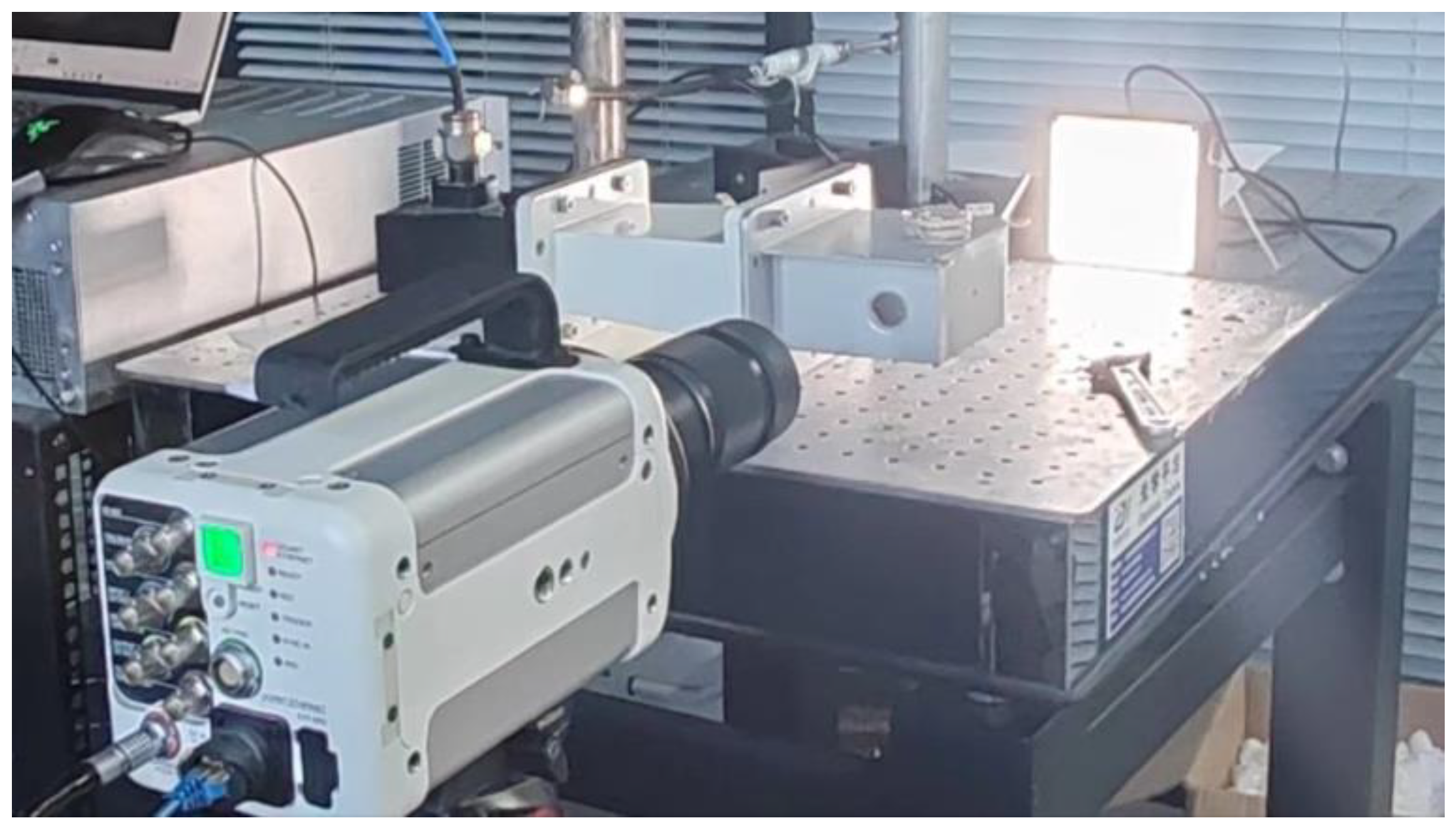
Figure 3.
Physical diagram of the microwave ignition experimental setup.
The resonant cavity, based on a BJ26 rectangular waveguide, measures 109.22 mm in length, 64.77 mm in width, and 96.1 mm in height, and is constructed entirely from pure aluminum. For test image acquisition purposes, windows with a 19 mm diameter are integrated at both the front and back ends of the resonator. These windows are positioned 30.5 mm (which corresponds to 1/4 wavelength) from the metal wall at the cavity’s end. They are made of indium tin oxide-coated glass, ensuring over 84% light transmittance while effectively containing microwave leakage.
Using tungsten wire electrodes is advantageous due to their excellent electrical and thermal conductivity, as well as their durability. Electrodes with a diameter of 0.5 mm are suspended 30.5 mm away from the rear wall of the resonant cavity, corresponding to a quarter-wavelength. These electrodes play a crucial role in concentrating the electromagnetic field within a limited area. The droplet suspended at the base of the electrode has a diameter of approximately 1.5 mm.
The experimental setup for image acquisition included a high-speed video camera (Photron Nova S9, Photron Ltd., Tokyo, Japan), a macro lens (Nikon 85 mm f/2.8 1–5× super macro, ZhongYi Optics Co., Ltd., Shenyang, China), a 100 W light-emitting diode (LED) backlight, and a computer. To ensure accurate observation and recording of instantaneous droplet combustion changes, the high-speed camera was set to a resolution of 1024 × 1024 (one million pixels) and a frame rate of 4000 frames per second (fps).
Before beginning the tests, the experimental setup, including the test bench and apparatus, was arranged to ensure the high-speed camera was aligned correctly with the droplet for optimal observation. Once the microwave resonance chamber was activated, the power was set to 250 W with a pulse width of 10 µs and varied duty cycles. Upon detecting the onset of the combustion phenomenon on the display, the camera was halted, and the entire ignition process was captured through photography. Subsequently, the acquired photos were subjected to data processing and analysis to generate test results. This testing procedure was repeated by adjusting the duty cycle and varying the pulse width accordingly.
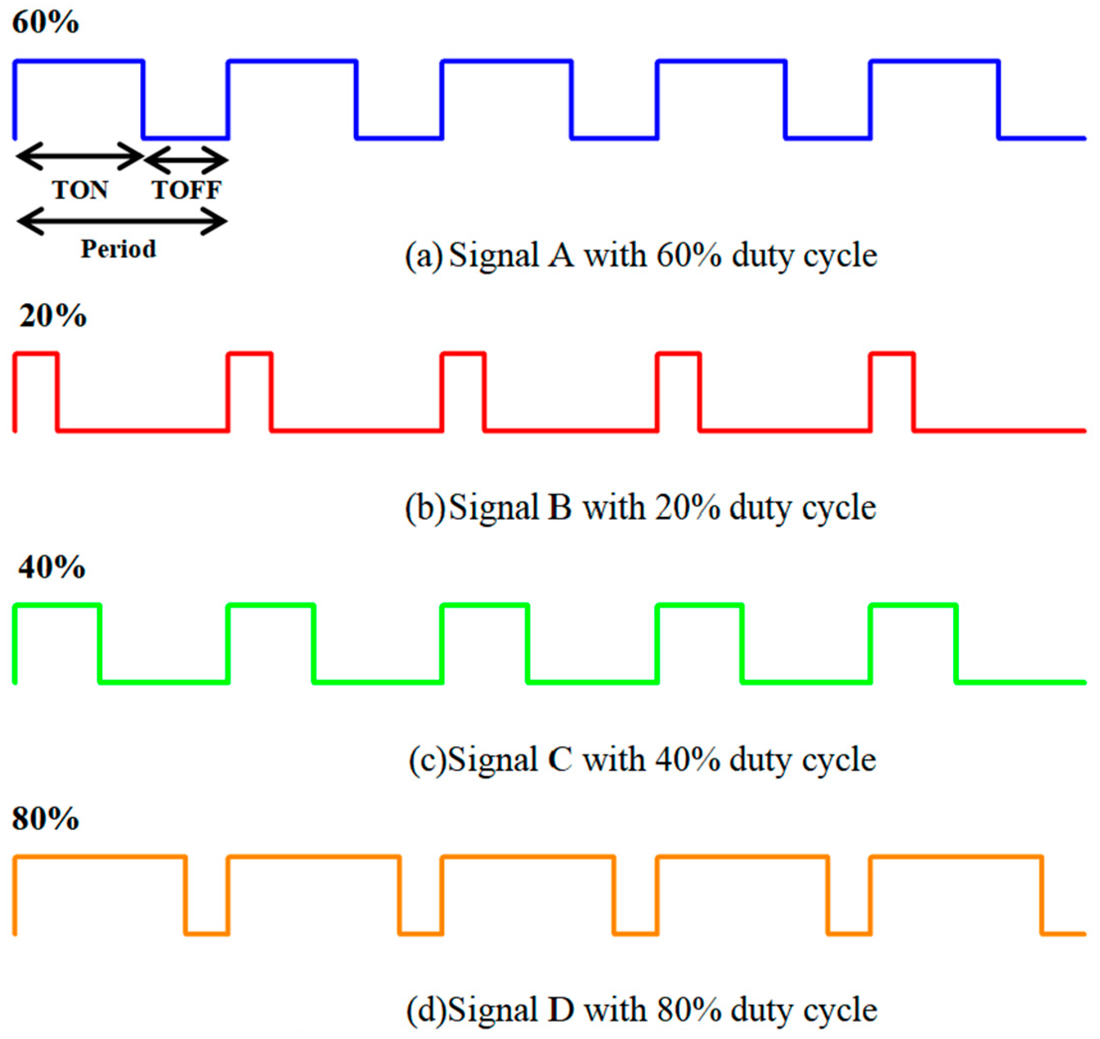
The square wave with a centralized duty cycle utilized in this study is depicted in Figure 4.

Figure 4.
Schematic diagram of a concentrated duty cycle square wave.
Five groups of experiments with different duty cycles and pulse widths are carried out and described in the following sections. In Figures 9, 12, 15, and 17, only the most representative group of data is selected for plotting to achieve the purpose of showing the change rule of droplet diameter and, at the same time, make the data points of the whole picture clearer.
2.3. Uncertainty Analysis
The error in this test primarily arises from the measurement of the droplet diameter, predominantly attributed to image processing. This error is largely influenced by factors such as environmental noise, pixel values in the image, and the accuracy of spatial resolution scale detection. To quantify this uncertainty, we utilize the Class A uncertainty combined with Kline’s uncertainty formula [26].
Let us consider a physical expression R:
Then, the variable representation of R is
The relative uncertainty of R is
where is a certain value of the expression R and is a variable with the value X.
Assuming that the droplets during ignition are always spherical, the uncertainty formula for the square of the droplet diameter is derived from Equation (3) as
Knowing that the uncertainty of the droplet volume is mm3 and the droplet volume is considered to be 1.8 μL, and the uncertainty of the square of the diameter of the droplet is 2.3%. The uncertainty of the flame area is about 4.2%.
3. Results
3.1. Effect of Microwave Duty Cycle on Single Droplet Evaporation and Ignition Characteristics
To investigate the influence of the microwave duty cycle on the evaporation and ignition characteristics of a single droplet, the microwave power was set to 250 W, and the microwave pulse width was fixed at 10 μs. The experiment was conducted under four different microwave duty cycle settings: 20%, 40%, 60%, and 80%, respectively.
In this experiment, the reference point (0s) marks the moment when the droplet shape initially undergoes slight changes. By closely observing the droplet ignition process, this study categorizes the microwave ignition process of ADN-based liquid propellant droplets into three distinct phases: bubble growth phase, expansion and micro-explosion phase, and combustion phase.
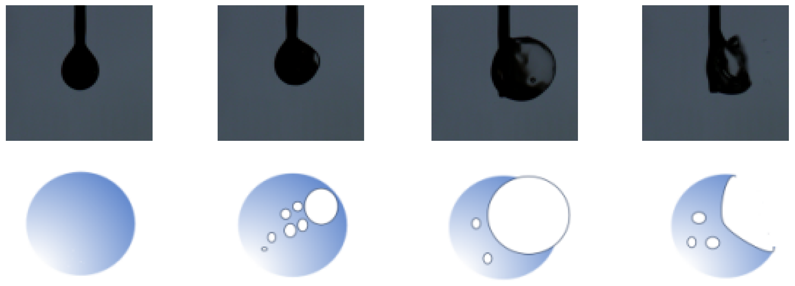
During the bubble growth stage of the droplet, a portion of the fuel inside the droplet undergoes evaporation and gasification, leading to the formation of bubbles. Figure 5 illustrates this stage, showing how droplets evolve under microwave influence during the test. Throughout this phase, the droplets undergo continuous volume changes and exhibit continuous vibrations along the tungsten rod due to microwave excitation. The emergence of numerous bubbles within the droplet is likely due to the microwave’s action mechanism. As these bubbles move toward the droplet surface, the forces acting at the gas–liquid interface become unbalanced against the surface tension, causing the bubbles to rupture.

Figure 5.
Schematic diagram of droplet expansion.
During the micro-explosion phase, the rapid vaporization of liquid droplets and the absorption of latent heat of vaporization result in a sharp decrease in droplet temperature. This temperature reduction is accelerated by a decrease in ambient pressure within the test vessel, which promotes intense convective evaporation. Consequently, the droplet’s cooling rate accelerates until equilibrium is reached with the ambient pressure inside the vessel. At this stage, the droplet’s evaporation rate slows down, eventually reaching its minimum temperature.
Following the accumulation of sufficient vapor within the droplet, internal pressure increases excessively, causing the vapor to rupture the droplet membrane, leading to a micro-explosion. This event releases a substantial amount of superheated vapor, which subsequently condenses upon contact with the low-temperature ambient gas, forming a significant amount of fog.
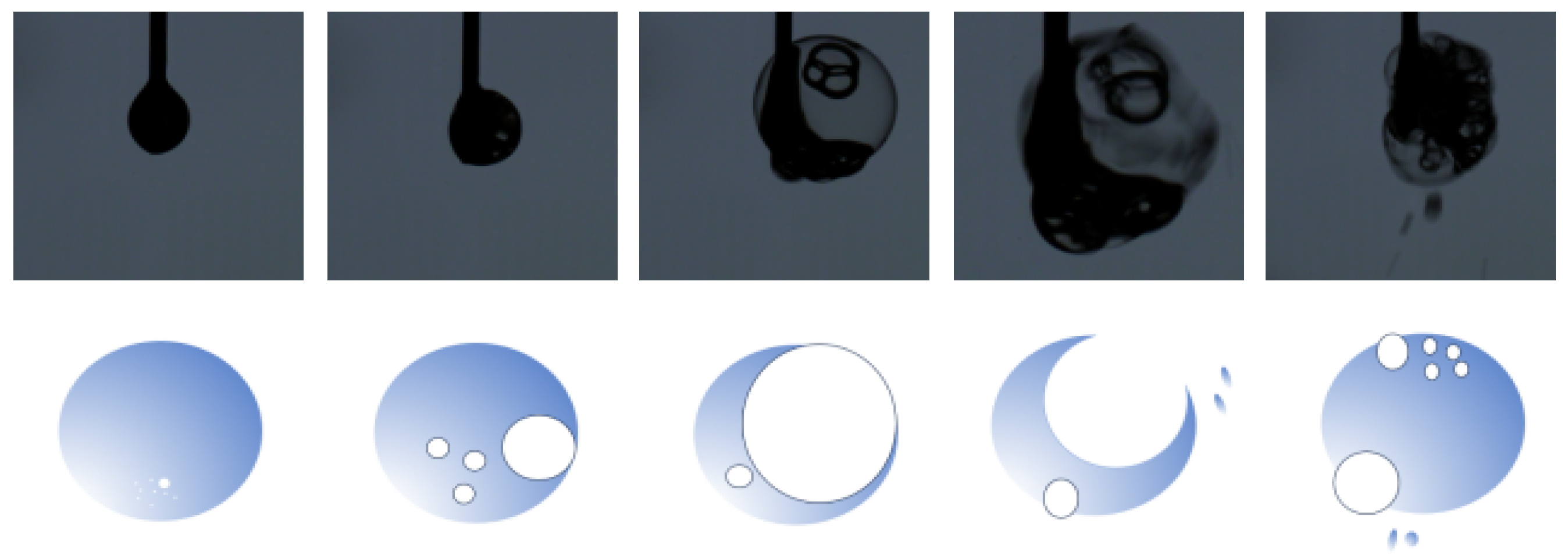
Figure 6 illustrates the process of droplet expansion micro-explosion under microwave excitation during the test. The micro-explosion phenomenon within the droplet is depicted, showing the formation of numerous bubbles inside the droplet and eventually protruding through its surface in microseconds.

Figure 6.
Schematic diagram of a droplet micro-explosion.
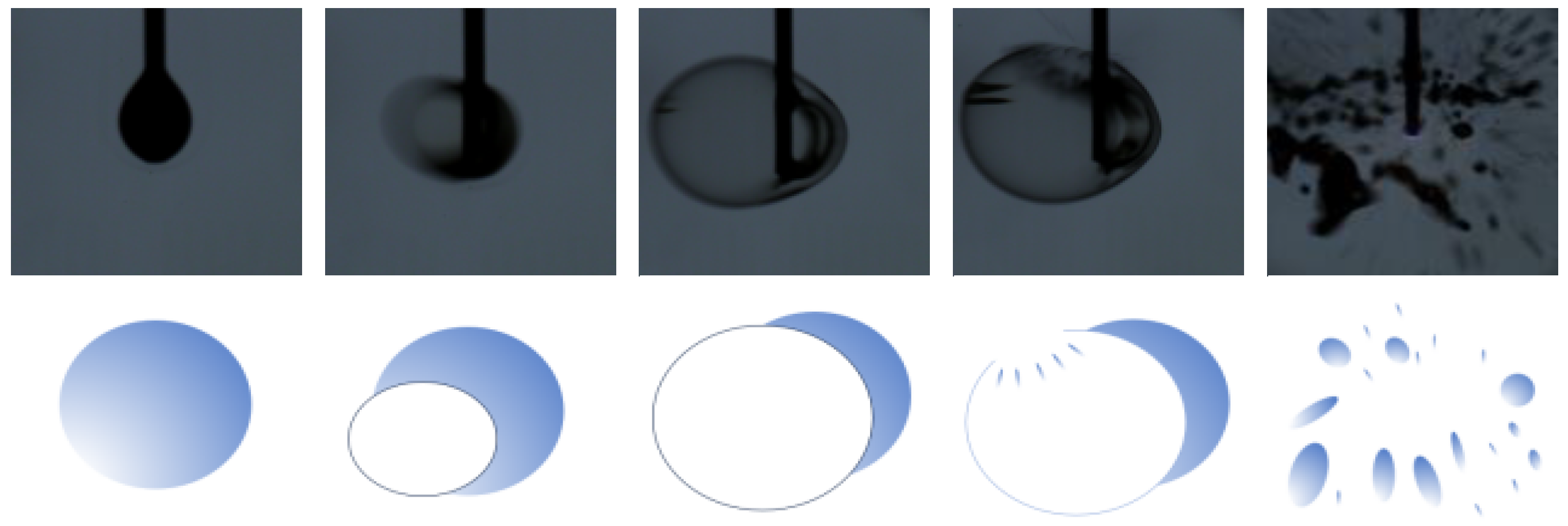
The test also observed a distinctive form of expansion, illustrated in Figure 7, where the droplet undergoes evaporation until reaching a critical temperature. Similar to a balloon, the droplet expands rapidly, transforming entirely into a bubble film. This remarkable expansion continues until the droplet ruptures, leaving no residual droplet attached to the tungsten rod. Subsequently, discharge ignition occurs at the end of the tungsten rod, initiating plasma combustion with ADN vapor. The outer layer of the flame appears yellow and is surrounded by bright white light, with no droplets remaining on the tungsten rod above the flame, indicating complete transformation into plasma combustion.

Figure 7.
Expansion processes in special cases.
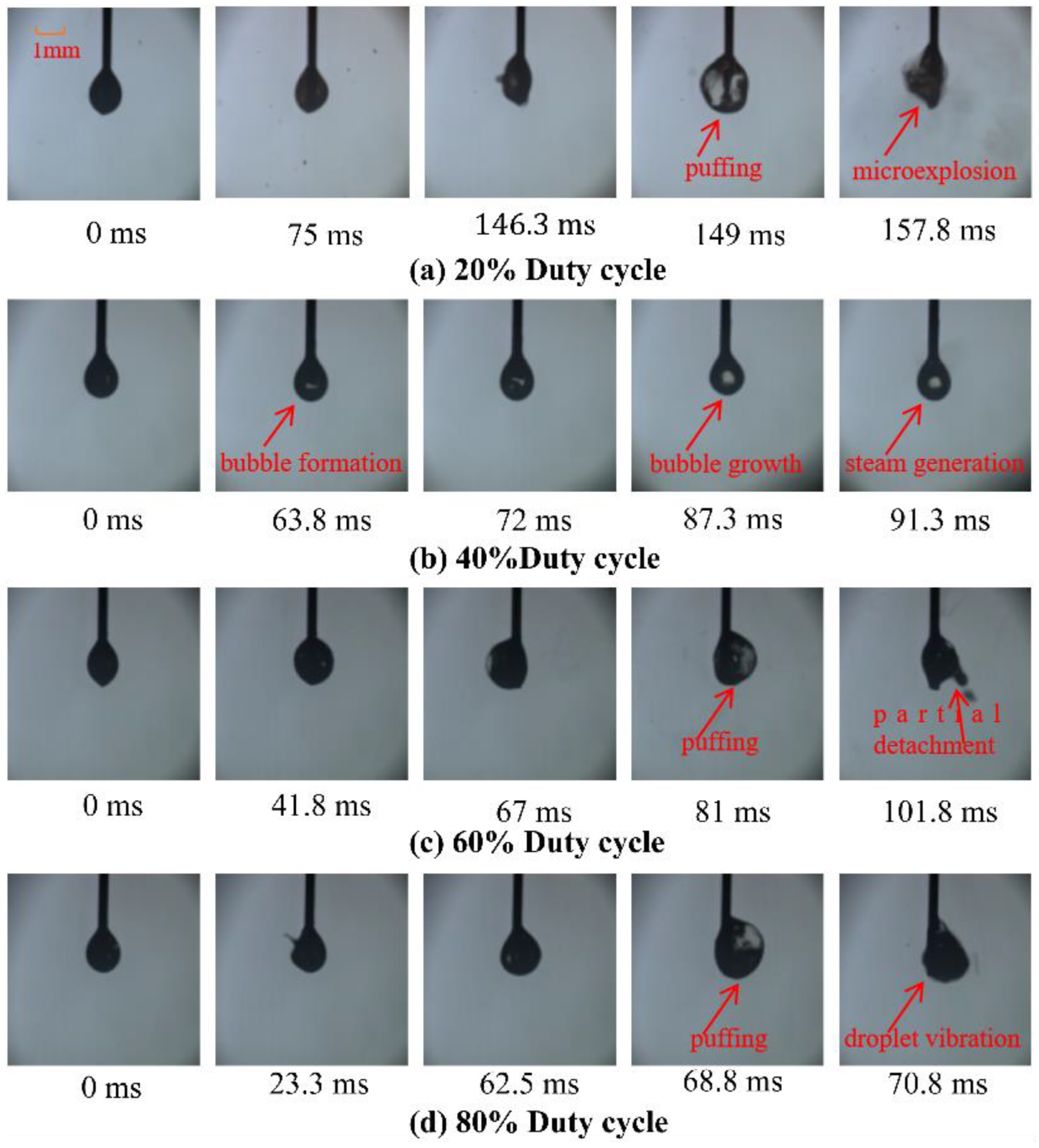
Figure 8 illustrates a sequence diagram depicting the stage of bubble growth and the expansion of the droplet microburst stage across various microwave duty cycles. Upon microwave excitation, the droplet’s surface exhibits slight vibration. Subsequently, the methanol component within the droplet, confined by the tungsten rod, begins to evaporate, leading to the formation of small bubbles of varying sizes. These small bubbles may initially display irregular movement and gradually expand over time, eventually merging with adjacent bubbles. Consequently, the droplet experiences outward pressure from the expanding bubbles, resulting in a phased expansion and contraction phenomenon. During the bubble generation stage, the absence of boiling on the outer surface of the droplet indicates a lower temperature on the outer surface compared to its interior. It can be inferred that evaporation occurs earlier on the inner surface of the droplet than on its liquid surface. This phenomenon may be attributed to the experimental utilization of the drop-hanging configuration, whereby the tungsten rod’s focusing effect on the electric field leads to enhanced heating within the droplet’s interior. Given the disparate evaporation characteristics of the components within the ADN droplet, particularly the lower boiling point of methanol, it is deduced that small bubbles form inside the droplet due to the earlier evaporation of the methanol component. As the droplet continues to absorb microwave energy, these small bubbles undergo growth and polymerization, rapidly expanding in volume. Additionally, influenced by surface tension and viscous forces, they undergo irregular movement and expansion.

Figure 8.
Schematic diagram of droplet evaporation and puffing under variable duty cycle.
Figure 9 illustrates the temporal variation of the visible diameter of the droplet over different microwave duty cycles. Due to the droplet’s irregular shape while suspended, the equivalent diameter mentioned here represents the circular diameter equivalent derived from its shaded area, adjusted by subtracting the area occupied by the tungsten filament inside the droplet at the corresponding moment. During the initial phase of bubble growth, the droplet volume remains relatively stable. However, in the later stages of bubble growth, there are notable fluctuations in the visible volume of the droplet, showing a discernible pattern of expansion, contraction, and subsequent expansion in its continuous cycle. As the duty cycle increases, the energy injected per unit of time rises, resulting in intensified heat accumulation around the tungsten rod. Consequently, the expansion phenomenon occurs earlier and becomes more pronounced, accompanied by a more significant volume change. For instance, at a duty cycle of 80%, at 68.8 ms, the expansion phenomenon becomes notably evident. This event occurs noticeably earlier compared to the expansion observed in the lower duty cycle test groups. Initially, the outer surface of the droplet ruptures prematurely, releasing internal gas, which causes the droplet’s surface to transit from a smooth curve to an undulating contour. Subsequently, the droplet experiences successive cycles of bubble growth, expansion, sharp contraction, and eventual complete fragmentation due to the microburst phenomenon. Additionally, some small droplets are ejected from the main droplet due to centrifugal force and gravity during this process. In the test group where expansion occurs earlier, the visualization of the droplet post-expansion reveals an increase in its visible diameter. However, owing to potential hollowness within and the intricate nature of the evaporation process, a simplistic correlation between droplet surface diameter and evaporation rate cannot adequately capture the complexity. Given the limitations of our experimental setup, distinguishing between the liquid and gas phases of the droplet in terms of volume distribution, internal pressure, flow field, and temperature distribution presents significant challenges. Consequently, to investigate the impact of the duty cycle and pulse width on the quantitative outcomes mentioned before, we measure the equivalent diameter of the expanded droplet and analyze its temporal evolution. This approach provides a more detailed understanding of how the duty cycle and pulse width impact the observed phenomena.

Figure 9.
Diagram of droplet diameter variation under variable duty cycle.
In this test, the delayed onset of ignition is defined as the period from the moment when there is a slight alteration in droplet shape to the ignition point at the tip of the tungsten rod. Subsequently, the ignition duration extends from the ignition point at the tungsten rod’s tip to the flame extinguishes. Figure 10 depicts sequence diagrams that illustrate the stages leading up to partial ignition at various microwave duty cycles, distinguishing the process into two distinct phases: the evaporation of the high-temperature droplet and the combustion of the ignited droplet.

Figure 10.
Image of droplet change before the first-time ignition: 20% duty cycle, 40% duty cycle, 60% duty cycle, and 80% duty cycle.
During the initial phase, the droplet undergoes microwave-induced evaporation within a high-temperature environment, with ADN vapor filling the resonant cavity. As the droplet evaporates, the air pressure within the droplet’s bubbles increases along with temperature, leading to gradual expansion. Upon reaching a critical threshold, the bubble film ruptures, leading to irregular deformation of the droplet influenced by various factors. Simultaneously, the evaporation process continues until the ADN vapor pressure reaches saturation. The presence of an oxidizing environment further enhances the evaporation process. The heat released during oxidation accelerates the evaporation rate of unburned fuel, thereby enhancing the overall evaporation rate.
Figure 11 illustrates the combustion sequence observed under different microwave duty cycles. In the test at the 20% duty cycle, the droplet undergoes continuous evaporation under the influence of microwave radiation. As the microwave exposure continues, vapor generated by the droplet’s evaporation undergoes combustion. At 177.8 ms, flame emerges from the thin filament discharge at the tip of the tungsten rod, igniting nearby methanol vapor within the droplet. This ignition results in a bright-colored flame surrounded by a dark mist in the immediate vicinity.

Figure 11.
Image of whole process of droplet change during the ignition: 20% duty cycle, 40% duty cycle, 60% duty cycle, and 80% duty cycle.
Upon ignition of the flame at the tip of the tungsten rod, residual droplets above it experience an accelerated evaporation rate, resulting in an intensification of the flame’s brightness. At 185 ms, the flame area reaches its maximum area. Subsequently, the flame begins to extinguish and gradually moves upward, following typical characteristics of gas-phase combustion. By 198.5 ms, the flame has completely disappeared from view.
Furthermore, the ignition and combustion process consumes a substantial amount of redox gas products from gasification decomposition, making the entire process exceptionally clean.
When the duty cycle is set at 40%, a visible bubble emerges within the droplet, accompanied by the high-temperature effect of the microwave. This bubble gradually expands at the center of the droplet, and ignition occurs between 91.5 ms and 91.9 ms. The resulting flame undergoes rapid changes, lasting only 14.3 ms before disappearing.
At a duty cycle of 60%, the emergence of black mist and scattering droplets coincides with the flame appearing at 132.5 ms. Within 0.3 ms, the flame emerges, transitioning to a white hue by 134.3 ms, indicative of plasma combustion. Subsequently, at 139 ms, the flame turns a bright yellow color. At 149.8 ms, the flame reaches its peak area, with intermittent plasma combustion within, while the outermost layer primarily comprises droplet vapor combustion. After 23 ms of combustion, the flame extinguishes.
Upon adjusting the duty cycle to 80%, the droplet undergoes an expansion process, generating bubbles that rupture multiple times, with peaks observed at 68.5 ms and 77.3 ms, respectively. At 88 ms, the flame reaches its maximum area after 14.3 ms. The flame disappears at 108.5 ms, marking the end of combustion.
Figure 12 presents the combustion delay time and combustion duration at various duty cycles. In the test conducted at 250 W, 10 µs, and 20% duty cycle, the ignition delay of the droplet was recorded at 177.8 ms. Subsequently, increasing the duty cycle to 40% resulted in a significant reduction of the ignition delay to 91.5 ms, marking a decrease of 48.5%. Further increasing the duty cycle to 60% resulted in an ignition delay of 132.8 ms. Finally, at an 80% duty cycle, the ignition delay further decreased to 88 ms. The longest ignition delay occurs at the 20% duty cycle, while the shortest ignition delay is observed at the 40% duty cycle. From the experimental results, it can be observed that as the duty cycle increases gradually from 20% to 60%, both ignition delay time and duration exhibit a trend of initially decreasing followed by increasing. This phenomenon is analyzed to be the result of the coupled influence of various factors on the combustion characteristics of ADN droplets, involving a complex interplay of multiple positive and negative factors in the combustion process. According to Figure 10 and Figure 11, the ignition and combustion states of droplets are influenced not only by the microwave energy duty cycle but also by the instantaneous bubble state inside the droplets. Compared to droplets without bubbles or with weak bubbles inside (Figure 10c), droplets with larger bubbles (Figure 10b,d) experience ionization and ignition earlier under the high-energy electric field of the microwave antenna, resulting in more intense combustion.

Figure 12.
Ignition delay and ignition time under variable duty cycle.
Figure 13 illustrates the flame width achieved under various duty cycle conditions. Using ImageJ software (ImageJ bundled with 64-bit Java 8) to identify the flame outline in the images, the maximum horizontal flame width during flame development is defined as the maximum flame width. The results indicate that the maximum flame width was observed at a duty cycle of 20%. In this particular test set, the ignition delay time was the longest, and droplet evaporation was the most thorough. Consequently, the fuel vapor was evenly distributed within the chamber, leading to a notably wide flame width.

Figure 13.
Flame widest equivalents under variable duty cycle.
Conversely, the other three duty cycle settings exhibited incomplete evaporation before ignition, resulting in smaller flame widths compared to the 20% duty cycle case.
3.2. Effect of Microwave Pulse Width on Single Droplet Evaporation and Ignition Characteristics
To investigate the influence of microwave pulse width on droplet combustion characteristics, microwave pulse widths of 10, 20, 30, 40, and 50 µs were selected. The microwave duty cycle was fixed at 40%, and the microwave power was set at 250 W.
Figure 14 depicts sequence diagrams illustrating the stages of bubble growth and puffing micro-explosion of the droplet under various microwave pulse widths. It is evident that as the pulse width increases, the duration of bubble puffing gradually extends. With smaller pulse widths, numerous small bubbles form inside the droplet, which absorb heat, constantly move, polymerize, and expand. Conversely, when the pulse width is 50 µs, typically only one bubble appears very stably near the tip of the tungsten rod, steadily increasing in volume. The shape and position of this bubble remain almost unchanged until it reaches a critical value, leading to an instantaneous microburst that causes the bubble to vanish. Consequently, the droplet’s surface vibrates irregularly, eventually causing the droplet to detach from the tungsten rod.

Figure 14.
Schematic diagram of droplet evaporation and expansion under variable microwave pulse width.
Furthermore, it is observed that the phenomenon occurs earlier and with more intense expansion when using smaller pulse widths. The rapid aggregation and expansion of small bubbles lead to their quick breakthrough through the droplet’s outer surface. As a result, a few droplets detach, causing a sharp reduction in the droplet’s outer diameter. Subsequently, the droplet expands again, and its visible diameter increases until it completely separates from the tungsten rod.
When a bubble escapes from the droplet, the surface tension equilibrium on the outer surface of the droplet is disrupted, causing the droplet’s outer contour to lose its smooth curvature. Additionally, a portion of the droplet’s surface undergoes microwave plasma evaporation, resulting in liquid fragmentation. While only a small amount of liquid exits the droplet, the loss of spherical shape increases the droplet’s surface area. Consequently, the contact area between the droplet and the microwave environment also expands, intensifying their interaction.
Microwave energy input induces localized changes in the droplet’s surface tension, leading to deformation from its original smooth, curved profile. Furthermore, microwave energy may trigger molecular vibrations within the droplet, further influencing its state and behavior. As sub-droplets dislodge and splash out from the parent droplet, there is a sudden decrease in the contact area between the droplet and the tungsten filament. This results in the complete detachment of the droplet from the tungsten filament.
During the free-fall process of the splashed droplets, the expansion phenomenon continues. While continuous growth and expansion of bubbles contribute to this phenomenon, it is primarily driven by pressure differences between the interior and exterior of the bubbles. These pressure differences cause the bubbles to rupture the surface of the droplets, influenced by centrifugal force and gravity.
Continued exposure to microwave energy results in more drastic changes in the droplet’s morphology, ultimately leading to micro-explosion or detachment from the tungsten rod. Droplets that are partially dislodged experience elevated temperatures, leading to secondary expansion and fragmentation under the influence of microwave energy.
Figure 15 illustrates the relationship between the equivalent diameter of the droplet and time during the micro-explosion stage of droplet expansion under different microwave pulse widths (10 µs, 20 µs, 30 µs, 40 µs, 50 µs). The curve in the figure exhibits sharp fluctuations, corresponding to various stages of droplet expansion, contraction, and micro-explosion. Observing the curve, it becomes evident that the droplet undergoes a cyclic process characterized by bubble generation and expansion, followed by visible volume increase, rupture, and ejection, resulting in droplet shrinkage. Subsequently, following the droplet expansion phenomenon, sub-droplets separate from the main droplet and are ejected. This is followed by a rapid contraction of the droplet, leading to a sudden reduction in equivalent diameter and distortion of the droplet’s shape. Throughout this process, the droplet continues to generate small bubbles, leading to bubble formation and growth, which ultimately triggers the next expansion phase. Analysis of the curves in the figure reveals that the initial expansion process of the low pulse width begins earlier compared to that of the group with high pulse widths. However, the volume change of the high pulse width group is larger, indicating more pronounced cycles of expansion and contraction.

Figure 15.
Diagram of droplet diameter variation under variable microwave pulse width.
Figure 16 and Figure 17 provide insights into the ignition delay and combustion duration under various pulse width conditions. As depicted, the longest ignition delay time occurs with a pulse width of 50 µs, while the longest combustion duration is observed with a pulse width of 40 µs. Figure 16 complements this by illustrating sequence diagrams of the ignition and combustion stages of the droplet across different pulse widths. Observations from the data reveal that ignition delay progressively lengthens with increasing microwave pulse width. For instance, at a pulse width of 10 µs, the minimum ignition delay recorded is 89 ms. However, when the pulse width is extended to 20 µs, the droplet’s evaporation rate decreases, slowing down the expansion process, thereby leading to a 57.6% increase in ignition delay compared to the previous group. Furthermore, the difference in ignition delay between the 20 µs and 30 µs pulse width groups is not significant. However, in the 30 µs group, droplet expansion leads to rupture and splashing. At 40 µs, although droplet expansion is noticeable, the slower expansion process due to the increased pulse width affects energy absorption and significantly delays ignition, with an ignition delay of 200.5 ms, representing a 57.6% increase compared to the 30 µs pulse width. This delay is also 39.9% longer than that observed with a 30 µs pulse width. Under the 50 µs condition, the droplet absorbs enough energy to expand directly from its center, resulting in rupture. The ignition delay reaches 243.3 ms, with only a few droplets remaining above the tungsten rod at ignition. Moreover, under identical duty cycle conditions, smaller pulse widths result in faster droplet evaporation, greater heat absorption, shorter ignition delays, and quicker droplet ignition.

Figure 16.
Droplet change before the first-time ignition: 10 μs, 20 μs, 30 μs, 40 μs, and 50 μs.

Figure 17.
Ignition delay and ignition time under variable pulse width.
Figure 18 illustrates the combustion sequence diagrams at different microwave pulse widths, highlighting changes in ignition duration with varying pulse widths. Notably, with a pulse width of 50 µs, the shortest ignition time recorded is 51.7 ms. In contrast, the 40 µs group exhibits 50% longer ignition time than the 50 µs group, a difference attributed to variations in droplet behavior during the evaporation process. Specifically, the 50 µs group retains more droplets on the tungsten rod throughout the combustion process, thereby accelerating droplet combustion. Conversely, in the 20 µs group, more droplets are observed to remain above the flame, resulting in shorter ignition times. This observation suggests that the ignition duration correlates closely with droplet residue, where greater residue is associated with shorter ignition times. Additionally, the time of droplet fragmentation is also believed to influence ignition duration.

Figure 18.
Process of droplet change during the ignition: 10 μs, 20 μs, 30 μs, 40 μs, and 50 μs.
As depicted in Figure 19, the maximum flame width varies across different pulse widths, with an increasing trend as the microwave pulse width increases. This phenomenon can be attributed to several factors. Firstly, as the pulse width increases, the droplet’s absorption of energy weakens, leading to a decrease in the droplet evaporation rate. However, despite the slower evaporation rate, the droplet’s evaporation becomes more thorough. This results in a more uniform distribution of fuel vapor throughout the container, which correlates positively with flame width. Consequently, the flame width is closely related to the ignition delay; a longer ignition process leads to more complete droplet evaporation and a more uniform fuel distribution, resulting in a larger flame width. Furthermore, as the flame width reaches its maximum, all droplets are completely evaporated, and none remains on the tungsten rod. Additionally, it is observed that the time taken to reach the maximum flame width also increases with the pulse width.

Figure 19.
Flame widest equivalents under variable pulse width.
The findings align with those discussed in the duty cycle group: a longer ignition delay leads to more thorough droplet evaporation under the action of microwaves. This results in a more uniform distribution of fuel vapor throughout the chamber, which allows the flame to burn with a larger volume of fuel vapors participating in combustion, therefore presenting a larger flame width.
4. Discussion
The analysis of Figure 20 reveals significant insights into the ignition position points relative to the tip of the tungsten rod, with a few situated on the shoulder of the tip. Notably, the ignition positions vary with changes in both the duty cycle and pulse width. In the variable duty cycle group, the ignition position gradually shifts to the right as the duty cycle increases. Similarly, in the variable pulse width group, the ignition positions move to the right as the pulse width increases. One plausible hypothesis for these observations is the shape of the microwave antenna’s tip. The inclination and smoothness of the antenna’s tip cross-section likely play a role in determining the ignition location. Furthermore, at the onset of ignition, the flame typically displays a predominantly spherical shape. However, as time advances, the surrounding fuel vapor gradually ignites, and the flame tends to become spherical form. Nevertheless, there are instances, such as the one depicted above, where liquid droplets above the flame have not completely evaporated, influencing the overall shape of the flame. Future research endeavors could concentrate on delving deeper into the factors that impact ignition position points, encompassing the design and geometry of the microwave antenna. Additionally, studying the effects of droplet characteristics and the surrounding atmosphere on flame shape evolution could provide deeper insights into combustion dynamics in similar setups. Such investigations could contribute to optimizing combustion systems for enhanced performance and efficiency.

Figure 20.
Images of the moment of ignition and special circumstances.
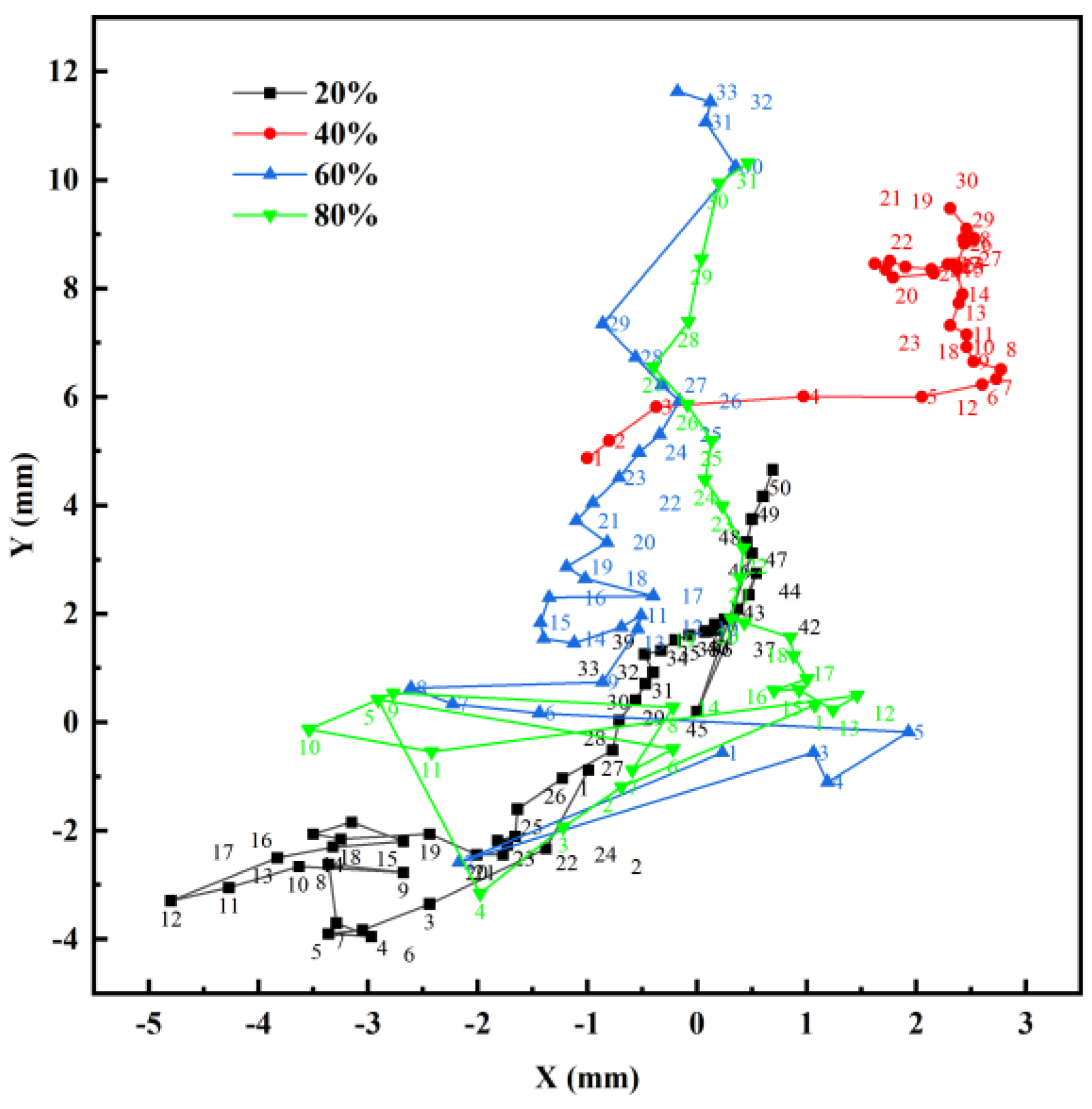
Figure 21 presents the trajectory diagram illustrating the movement of the flame center relative to the tip of the needle, which serves as the coordinate origin. The trajectory begins with the ignition point near the coordinate origin, gradually shifting upward over time. The left and right orientation of the flame center is influenced by the density of fuel vapor within the combustion chamber. Additionally, the presence of liquid droplets above the flame, if not completely evaporated, can also impact both the shape of the flame and the position of its center.

Figure 21.
Image of the movement trajectory of the center of the flame with a variable duty cycle.
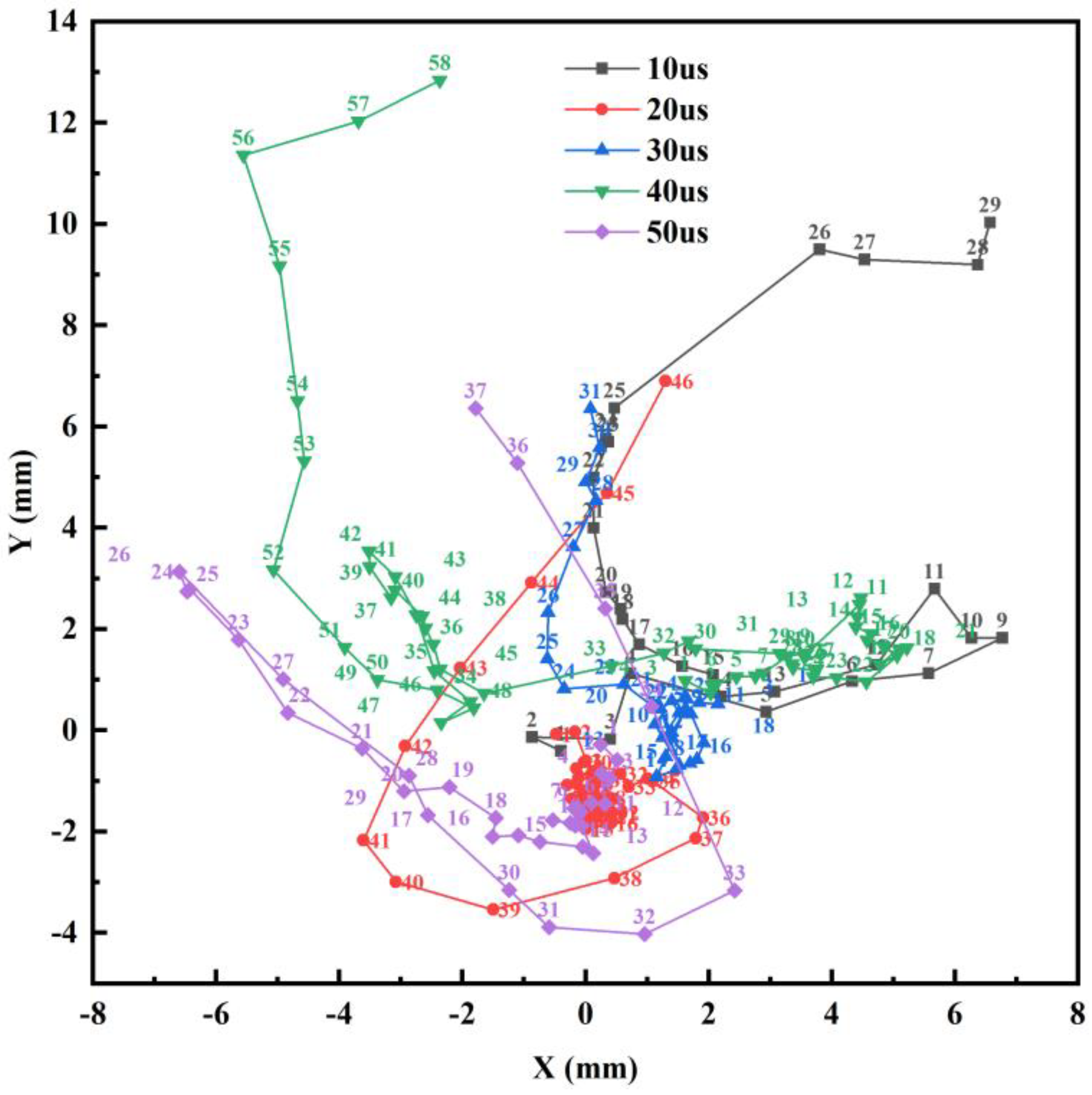
Figure 22 illustrates the trajectory diagram depicting the movement of the flame center relative to the tip of the needle, used as the coordinate origin, for the variable pulse width group. The trajectory begins with ignition near the coordinate origin, followed by a phenomenon of a left-right offset. Compared to the variable duty cycle group test, this group exhibits a more common and pronounced flame center shift phenomenon. These shifts are predominantly attributed to the presence of droplets above the flame that have not completely evaporated.

Figure 22.
Image of the movement trajectory of the flame center with a variable pulse width.
Regarding the experimental results, it was initially assumed that higher duty cycles would result in smaller ignition delays for the droplets, following a linear trend. However, the experimental findings have shown otherwise. Specifically, the results indicate that while the 80% duty cycle exhibits the smallest ignition delay, the delay for the 40% duty cycle is larger but very close to that of the other two groups. This suggests a non-linear relationship between duty cycle and ignition delay, highlighting the complex interplay of factors influencing droplet combustion dynamics. Further investigation is warranted to elucidate the underlying mechanisms governing these observed phenomena and to optimize combustion processes for improved efficiency and performance.
In the experiments with variable pulse width, a 40% duty cycle was chosen for quantitative analysis. This decision was motivated by several factors. Firstly, selecting a low duty cycle with a low firing delay holds particular significance as it represents a scenario where ignition occurs promptly despite minimal microwave energy input. Additionally, opting for a low duty cycle signifies a smaller proportion of high-power microwave radiation, potentially conserving energy and facilitating subsequent microwave effects.
In this set of experiments, a clear trend emerges where larger pulse widths result in longer ignition delays. However, it is noteworthy that there are slight variations in firing delays under identical conditions across the two sets of experiments. Such minor differences are deemed acceptable considering the timing constraints and external conditions inherent in the experiments.
One important factor contributing to these differences could be the variance in experimental time, leading to fluctuations in external temperature conditions. Additionally, variations in droplet size and the specific positioning of each experiment may also contribute to subtle differences in firing delays. These factors underscore the intricate nature of droplet combustion dynamics and highlight the need for careful consideration of experimental parameters to ensure accurate and reliable results.
5. Conclusions
This study explores the influence of microwave duty cycle and pulse width on the evaporation and ignition behavior of ADN-based liquid droplets. By varying the microwave duty cycle and pulse width, the micro-explosion, evaporation, and ignition processes are analyzed. The main conclusions are as follows:
- (1)
- When subjected to microwave irradiation, ADN-based liquid propellant droplets undergo expansion and micro-explosion phenomena. As the duty cycle increases, so does the energy injected per unit of time, resulting in heightened heat accumulation around the tungsten rod. The expansion phenomenon occurs earlier and becomes more pronounced, accompanied by a more intense volume change.
- (2)
- The ignition and combustion state of droplets are influenced not only by the microwave energy duty cycle but also by the instantaneous bubble state inside the droplets. Compared to droplets without bubbles or with weak bubbles inside, droplets with larger bubbles experience ionization and ignition earlier under the high-energy electric field of the microwave antenna, resulting in more intense combustion.
- (3)
- As the pulse width increases, the duration of bubble puffing gradually extends. With smaller pulse widths, numerous small bubbles form inside the droplet. When the pulse width is large, typically only one bubble appears very stably near the tip of the tungsten rod, steadily increasing in volume. The ignition delay gradually increases with the rise in microwave pulse width. Smaller pulse widths result in faster droplet evaporation, greater heat absorption, shorter ignition delays, and quicker droplet ignition. The maximum flame width varies across different pulse widths, with an increasing trend observed as the microwave pulse width increases.
- (4)
- The majority of firing positions are located below the tip of the needle, with a few situated on the shoulder of the tip. Notably, the ignition position point exhibits variation with changes in both the duty cycle and pulse width. In the variable duty cycle group, the ignition position point gradually shifts to the right as the duty cycle increases.
This study explores the effects of microwave energy duty cycle and pulse width on the micro-explosion and ignition characteristics of ADN-based propellant droplets, providing crucial foundational data for the development of microwave ignition propulsion systems. Current research findings highlight the significant influence of bubble development and spatial positioning within droplets under microwave irradiation on micro-explosion and ignition performance. Future studies could delve into aspects such as bubble kinematics, dynamics, and composition.
Author Contributions
Conceptualization, D.Y. and Y.Y.; methodology, Y.H.; validation, D.Y., J.Y., and J.M.; formal analysis, D.Y.; resources, Y.Y.; writing—original draft preparation, D.Y., J.Y., and J.M.; writing—review and editing, S.Z.; supervision, Y.Y. All authors have read and agreed to the published version of the manuscript.
Funding
This research was supported by the National Natural Science Foundation of China (Grant No. U21B2074), and Beijing Engineering Research Center of Efficient and Green Aerospace Propulsion Technology and Advanced Space Propulsion Laboratory of BICE, No: LabASP-2023-08.
Institutional Review Board Statement
Not applicable.
Informed Consent Statement
Not applicable.
Data Availability Statement
Some data, models, or code that support the findings of this study are available from the corresponding author upon reasonable request.
Conflicts of Interest
The authors declare no conflicts of interest.
References
- Omer, A.M. Energy, environment and sustainable development. Renew. Sustain. Energy Rev. 2008, 12, 2265–2300. [Google Scholar] [CrossRef]
- Wu, J.; Bruce, F.N.O.; Bai, X.; Ren, X.; Li, Y. Insights into the Reaction Kinetics of Hydrazine-Based Fuels: A Comprehensive Review of Theoretical and Experimental Methods. Energies 2023, 16, 6006. [Google Scholar] [CrossRef]
- Clark, D.A. Pharmacology and Toxicology of Propellant Hydrazines; USAF School of Aerospace Medicine, Aerospace Medical Division: San Antonio, TX, USA, 1968. [Google Scholar]
- Lei, L.I.; Guoxiu, L.I.; Hongmeng, L.I.; Zhaopu YA, O.; Zhang, T.; Jinze, W.U.; Zhang, S. Effects of ignition voltage and electrode structure on electric ignition and combustion characteristics of Ammonium Dinitramide (ADN)-based liquid propellants in electric ignition mode in inert gas environment. Chin. J. Aeronaut. 2024, 37, 229–242. [Google Scholar] [CrossRef]
- Amrousse, R.; Hori, K.; Habu, H.; Fujisato, K.; Royer, S.; Laassiri, S. Characterization and decomposition of ammonium dinitramide as liquid propellant. Int. J. Energetic Mater. Chem. Propuls. 2011, 10, 245–257. [Google Scholar] [CrossRef]
- Yoon, W.; Bhosale, V.K.; Yoon, H. Performance Evaluation of Ammonium Dinitramide-Based Monopropellant in a 1N Thruster. Aerospace 2024, 11, 110. [Google Scholar] [CrossRef]
- Anflo, K.; Crowe, B.; Persson, M. The fist in-space demonstration of a green propulsionsystem. In Proceedings of the 24th Annual Conference on Small Satellites, Logan, UT, USA, 9–11 August 2010. [Google Scholar]
- Yao, Z.; Zhang, W.; Wang, M.; Chen, J.; Shen, Y.; Wei, Y.; Yu, X.; Li, F.; Zeng, H. Tunable diode laserabsorption spectroscopy measurements of high-pressure ammonium dinitramidecombustion. Aerosp. Sci. Technol. 2015, 45, 140–149. [Google Scholar] [CrossRef]
- Zhang, T.; Li, G.X.; Yu, Y.S.; Sun, Z.Y.; Wang, M.; Chen, J. Numerical simulation ofammonium dinitramide (ADN)-based non-toxic aerospace propellantdecomposition and combustion in a monopropellant thruster. Energ. Conver. Manag. 2014, 87, 965–974. [Google Scholar] [CrossRef]
- Zhang, T.; Li, G.X.; Yu, Y.S.; Chen, J.; Wang, M. Effects of catalytic bed thermacharacteristics on liquid monopropellant decomposition and combustioncharacteristics within an eco-friendly thruster based on ammonium dinitramide. Combust. Sci. Technol. 2016, 188, 910–923. [Google Scholar] [CrossRef]
- Jing, L.; Zhu, M.; Wang, H.; You, X.; Yao, Z. Flame structure of ammonium-dinitramide-based liquid propellant in a small thruster. J. Propuls. Power 2018, 34, 1131–1139. [Google Scholar] [CrossRef]
- Trimm, D.L.T. Catalytic combustion. Appl. Catal. 1983, 7, 249–282. [Google Scholar] [CrossRef]
- Bernhardt, W.E.; Hoffmann, E. Methods for fast catalytic system warm-up during vehicle cold starts. SAE Trans. 1972, 81, 1654–1667. [Google Scholar]
- Andreasson, S.; Bemm, E.; Larsson, A.; Nyholm, S.E. Evaluation of an electrothermal-chemical concept where propellant combustion is stimulated by conducting electric current through the flame. IEEE Trans. Magn. 2005, 41, 338–343. [Google Scholar] [CrossRef]
- Negri, M.; Wilhelm, M.; Hendrich, C.; Wingborg, N.; Gediminas, L.; Adelöw, L.; Maleix, C.; Chabernaud, P.; Brahmi, R.; Beauchet, R.; et al. New technologies for ammonium dinitramide based monopropellant thrusters—The project RHEFORM. Acta Astronaut. 2018, 143, 105–117. [Google Scholar] [CrossRef]
- Hirsch, N.; Gallatz, A. Space ignition method using microwave radiation. MTZ Worldw. 2009, 70, 32–35. [Google Scholar] [CrossRef]
- Cheng, J.; Cao, J.; Li, F.; Zhang, Z.; Xu, J.; Ouyang, K.; Rossi, C.; Ye, Y.; Shen, R. Microwave controlled ignition and combustion characteristics of ADN-based ionic liquid propellant with fast response and environmental friendliness. Chem. Eng. J. 2023, 471, 144412. [Google Scholar] [CrossRef]
- Hwang, J.; Bae, C.; Park, J.; Choe, W.; Cha, J.; Woo, S. Microwave-assisted plasma ignition in a constant volume combustion chamber. Combust. Flame 2016, 167, 86–96. [Google Scholar] [CrossRef]
- DeFilippo, A.C. Microwave-Assisted Ignition for Improved Internal Combustion Engine Efficiency; University of California: Berkeley, CA, USA, 2013. [Google Scholar]
- Wolk, B.; DeFilippo, A.; Chen, J.Y.; Dibble, R.; Nishiyama, A.; Ikeda, Y. Enhancement of flame development by microwave-assisted spark ignition in constant volume combustion chamber. Combust. Flame 2013, 160, 1225–1234. [Google Scholar] [CrossRef]
- Wang, Z.; Wang, Y.; Zhu, L.; Ma, W.; Shan, J.; Liu, F. Experimental study of influence on microwave plasma ignition combustion performance of pulse microwave signals. IEEE Access 2019, 7, 23951–23958. [Google Scholar] [CrossRef]
- Hemawan, K.W.; Romel, C.L.; Zuo, S.; Wichman, I.S.; Grotjohn, T.A.; Asmussen, J. Microwave plasma-assisted premixed flame combustion. Appl. Phys. Lett. 2006, 89, 141501. [Google Scholar] [CrossRef]
- Hemawan, K.W.; Wichman, I.S.; Lee, T.; Grotjohn, T.A.; Asmussen, J. Compact microwave re-entrant cavity applicator for plasma-assisted combustion. Rev. Sci. Instrum. 2009, 80, 053507. [Google Scholar] [CrossRef]
- Hou, Y.; Yu, S.Y.; Li, Y.; Liu, X.; Yao, Z.; Zhang, Y.S. Experimental study on microwave ignition of ADN-based liquid propellant droplets doped with alumina nanoparticles. J. Phys. D Appl. Phys. 2024, 57, 145505. [Google Scholar] [CrossRef]
- Shen, J.; Yu, Y.; Liu, X.; Cao, J. Experimental research on microwave ignition and combustion characteristics of ADN-based liquid propellant. Micromachines 2022, 13, 510. [Google Scholar] [CrossRef] [PubMed]
- Hou, Y.; Yu, Y.; Li, Y.; Liu, X.; Wang, X. Experimental study on microwave-induced puffing, micro-explosion, and combustion characteristics of ammonium dinitramide-based liquid propellant droplets. Phys. Fluids 2023, 35, 117122. [Google Scholar] [CrossRef]
Disclaimer/Publisher’s Note: The statements, opinions and data contained in all publications are solely those of the individual author(s) and contributor(s) and not of MDPI and/or the editor(s). MDPI and/or the editor(s) disclaim responsibility for any injury to people or property resulting from any ideas, methods, instructions or products referred to in the content. |
© 2024 by the authors. Licensee MDPI, Basel, Switzerland. This article is an open access article distributed under the terms and conditions of the Creative Commons Attribution (CC BY) license (https://creativecommons.org/licenses/by/4.0/).