Article

Semianalytical Research on Aerothermoelastic Behaviors of Functionally Graded Plates under Arbitrary Temperature Fields in Hypersonic Vehicles

1
School of Aeronautic Science and Engineering, Beihang University, Beijing 100191, China
2
Institute of Unmanned System, Beihang University, Beijing 100191, China
*
Author to whom correspondence should be addressed.
Aerospace 2024, 11(7), 572; https://doi.org/10.3390/aerospace11070572
Submission received: 28 March 2024 / Revised: 8 July 2024 / Accepted: 10 July 2024 / Published: 12 July 2024
(This article belongs to the Special Issue Aeroelasticity, Volume IV)

Abstract

:
Hypersonic vehicles are susceptible to considerable aerodynamic heating and noticeable aerothermoelastic effects during flight due to their high speeds. Functionally graded materials (FGMs), which enable continuous changes in material properties by varying the ratio of different materials, provide both thermal protection and load-bearing capabilities. Therefore, they are widely used in thermal protection structures for hypersonic vehicles. In this work, the aerothermoelastic behaviors of functionally graded (FG) plates under arbitrary temperature fields are analyzed via a semianalytical method. This research develops a method considering the influence of thermal loading, specifically the decrease in stiffness due to thermal stresses, as well as the correlation between material properties and temperatures under arbitrary temperature fields, based on Ritz’s method. The classical plate theory, von–Karman’s large defection plate theory and piston theory are employed to formulate the strain energy, kinetic energy and external work functions of the system. This paper presents a novel analysis of static aerothermoelasticity of FG plates, in addition to the linear/nonlinear flutter under arbitrary temperature fields, such as uniform, linear and nonlinear temperature fields. In addition, the effects of the volume fraction index, dynamic pressure, and temperature increase on the aerothermoelastic characteristics of FG plates are analyzed.

1. Introduction

Hypersonic vehicles, defined as vehicles with a flight Mach number greater than 5, have emerged as a crucial area of interest in aerospace applications due to their rapid flight speed, robust defense capability, and extended flight range. A substantial amount of aerodynamic heat is generated during flight because of the significant air friction. There is a complex coupling effect with the structure, resulting in aerothermoelastic behaviors. Notably, panel flutter occurs in supersonic vehicles and can drastically affect their safety and durability. Several scholars have conducted groundbreaking studies on panel flutter. In earlier researches, linear analysis was used to study panel flutter [1]. Later, Dowell [2] conducted a study of two- and three-dimensional plates undergoing limit cycle oscillations using von Karman’s large deflection plate theory and quasisteady aerodynamic theory. Additionally, the Galerkin method was used to solve discretely considered in-plane and static pressure differentials. The findings indicated that the limit cycle deflection, stress, and frequency are functions of the dynamic pressure, air/panel mass ratio, static pressure differential, in-plane load and length-to-width ratio. The findings indicated that four to six modes can yield accurate results. There are also numerous methods for the nonlinear analysis of panel flutter, such as the finite element frequency domain method proposed by Xue and Mei [3] and the aeroelastic modes proposed by Guo and Mei [4]. McNamara and Friedmann concluded the aeroelastic and aerothermoelastic analyses of hypersonic flow in their review paper [5]. Zhou [6] conducted an aerothermoelastic analysis of moderately thick orthotropic plates with general boundary conditions. Quan [7] conducted an analysis of the post-flutter aerothermoelastic characteristics of hypersonic skin panels using a CFD-based approach.
Due to severe aerodynamic heating, it is often crucial to apply a thermal protective layer on the surface to safeguard the structures and devices inside a vehicle. The thermal insulation layer and the structural layer consist of disparate materials with distinct mechanical characteristics, which can cause stress concentration, delamination, peeling, and other interfacial phenomena, impairing structural integrity and safety. In order to avoid this phenomenon, Japanese researchers proposed the concept of functionally graded materials (FGMs), which involves the continuous alteration of the material properties of two or more materials by varying their compositions and structures. This ensures that there is no discernible interface or structural mutation. This continuous variation in material properties promotes the use of FGMs as crucial elements of thermal protective systems for hypersonic vehicles, which has been extensively researched by scholars investigating the phenomenon of panel flutter. It is beneficial to investigate panel flutter for suppression of flutter and optimization. Song [8] moderated the mode of localized airflow in the direction of the flow, for supersonic airflows, by designing axial FGMs to alter the thickness and material properties according to a specific law. The introduction of material property changes led to a significant enhancement in comparison to solely adjusting the thickness, resulting in the passive suppression of flutter. Wei [9] examined the flutter characteristics of axial functionally graded column shells, which could be improved by adjusting the thickness and material properties in the axial direction. Muc and Flis [10] studied the flutter and free vibration characteristics of functionally graded porous plates using analytical and Rayleigh–Ritz methods. Optimization can effectively increase the natural frequency and critical dynamic pressure according to the outcome of a variable parameter analysis. In recent years, novel structures based on the concept of FGMs have been created and analyzed. These structures include functionally graded graphene nanoplatelet-reinforced composite (FG-GPLRC) cylindrical panels [11,12,13], cracked functionally graded plates [14], FG multilayered graphene platelet-reinforced polymer composites (GPL-RPC) [15,16], FG porous doubly curved panels with piezoelectric layers [17], imperfect FG cylindrical shells [18], magnetic–electric–thermoelastic functionally graded plates [19], carbon-based nanohybrid composite panels [20], FG variable thickness blades [21], and cylindrical sandwich panels with FG-saturated porous cores [22], etc.
Thermal loads significantly impact the structural integrity of hypersonic vehicles, so there have been numerous investigations into the panel flutter of FGM structures in thermal environments. Several plate theories are commonly used in FGM modeling, including classical plate theory (CPT), first-order shear deformation theory (FSDT) [23,24,25], higher-order shear deformation theory (HSDT) [26], and other novel shear deformation theories, such as trigonometric shear deformation theory [27]. Equations governing shear-deformation theories of plates are typically more complicated and can take shear effects into consideration, which should be not neglected in thick plates [28]. However, the shear deformation theories lead to more complicated and less intuitive results than CPT that can characterize physical laws of plates directly. In aircrafts, thin-wall structures are commonly used. For thin plates, shear effects are so tiny that CPT can satisfy the accuracy need through fewer computations. Different methods are used to analyze the panel flutter of FG plates, such as finite element method (FEM) [29,30], Rayleigh–Ritz methods [10], Galerkin method [31,32], meshless method [33] and generalized differential quadrature method (GDQM) [34,35]. Praveen and Reddy [36] employed a finite element approach that considered shear strain to assess both the static and dynamic responses of ceramic–metal FG plates under different transient temperature fields. Ibrahim [37,38,39] employed a finite element technique based on first-order shear deformation theory and classical plate theory, respectively, to analyze the nonlinear flutter and thermal buckling issues of FG plates subjected to aerodynamic, thermal, and random acoustic loads. Navazi and Haddadpour [31,32] examined the impact of various parameters on the nonlinear aeroelastic behavior of semi-infinite FG plates using the Galerkin method. It was found that FG plates made of temperature-sensitive materials using the Mori–Tanaka model demonstrated less stability than those utilizing a simple power-law model. Su [40] proposed a unified method for the consideration of vibrations and flutter in elastically constrained FG plates under nonlinear temperature fields. The method involved the use of a modified Fourier series as a displacement basis function to express the displacement field of the reinforcement through the displacement variable of the plate, thereby eliminating the need for additional displacement variables. Lee and Kim [41] investigated the thermal postbuckling and snap-through instabilities of FG plates in hypersonic flows.
Most studies on panel flutter of FG plates are conducted in uniform or nonlinear temperature fields. However, the temperature field inside the structure of hypersonic vehicles can often become complex due to the influence of thermal loads. Therefore, it is necessary to establish an aerothermoelastic analysis method that can accommodate arbitrary temperature fields. Additionally, thermal stress and the relationship between properties and temperature should be taken into account simultaneously in thermal environments.
However, among the various aerothermoelastic behaviors, current studies have mostly concentrated on panel flutter for FG plates. There is a glaring lack of static aerothermoelastic studies examining aeroelastic responses in a certain temperature field in hypersonic flows. To investigate the influence of different variables on aerothermoelastic behaviors of FGM plates and provide a basis for design and optimization of FGM structures, concise solutions are needed. Therefore, aerothermoelastic analysis based on CPT and Ritz method is helpful to acquire a semianalytical solution for the FGM plate response.
In this study, an aerothermoelastic analysis was conducted via a semianalytical method. Static aerothermoelastic, linear panel flutter, and nonlinear panel flutter behaviors were imposed on simply supported FG plates. Equilibrium equations were established using classical plate theory and the Ritz method under arbitrary temperature fields in general forms, such as uniform, linear, and nonlinear temperature fields. Thermal stress and temperature-dependent properties were focused on in analytical expressions. The von Karman’s strain–displacement relationship was used to consider geometric nonlinearity, and the stress function is used for simplification in case of jointly solved the multivariable partial differential equations. The effects of the volume fraction index, aerodynamic pressure, and thermal load were investigated.

2. Methods

In this section, the relevant theories including structure modeling of FGM, thermal effects, and aerodynamic modeling are briefly presented to serve for theoretical derivations. The semianalytical expressions of aerothermoelasic behaviors of FG plates are also presented.

2.1. FGM Properties

Unlike those of conventional homogeneous materials, the properties of FGMs vary because they consist of a blend of two components. For metal–ceramic FGMs, which are commonly used in hypersonic vehicles, modifications in properties are attained based on a continuous component gradient.
The Voigt model is used here to determine the effective material properties. The FGM properties can be represented by the following equation:
P ( z ) = P m ( 1 V c ( z ) ) + P c V c ( z )
where P(z), Pc, and Pm express the properties of the FGM, ceramic and metal, respectively. The subscripts c, m and cm denote the properties of the ceramic and metal and the difference between the ceramic and metal, that is,
P c m = P c P m
The FG plate coordinates are presented in Figure 1. The airflow is assumed to be in the x-direction, and the z-coordinate is measured from the mid-plane of the plates, where a, b, and h denote the length, the width, and the thickness of the FG plate, respectively. The relationship between the ceramic volume ratio, Vc and the z-coordinate can be expressed as follows:
V c ( z ) = ( 1 2 + z h ) k
where k is the volume fraction index of the FGM.
Therefore, for FG plates, the material properties vary according to the location in the thickness direction as follows:
P ( z ) = P m + P c m ( 1 2 + z h ) k

2.2. Constitutive Relations

This study focuses on the modeling and characterization of FG thin plates, which are predominantly utilized in aircrafts. Thin-walled structures with small shear effects are commonly used in aircraft, making the classical plate theory (CPT) an appropriate choice for analysis due to its speed and simplicity of application. Because of the asymmetry of the material in the thickness direction of FG plates, the strain on the geometric middle surface is not 0. Instead, the physical neutral surface has a strain of zero. When subjected to a bending load, only the axial force is applied on this plane, with no moment. The distance between the physical neutral surface and the geometric middle surface, z0 can be expressed as [42]
z 0 = h / 2 h / 2 z E ( z ) d z h / 2 h / 2 E ( z ) d z = ( E c E m ) h k 2 ( E c + E m k ) ( k + 2 )
where E(z), Ec, and Em are the elastic moduli of the FGM, the ceramic, and the metal, respectively.
The strains on the FG plates can be expressed through the deflection function, w, as
ε x = 2 w x 2 ( z z 0 ) ε y = 2 w y 2 ( z z 0 ) γ x y = 2 2 w x y ( z z 0 )
According to the plane stress assumption, the stress on the FG plates can be expressed as
σ x = E ( z ) 1 ν 2 ( ε x + ν ε y ) σ y = E ( z ) 1 ν 2 ( ε y + ν ε x ) τ x y = E ( z ) 2 ( 1 + ν ) γ x y
where υ is Poisson’s ratio.

2.3. Thermal Effects on FGM

High-temperature environments are frequently encountered when using FGMs. Such environments subject structures to intense conditions, revealing structural flaws that might not surface at lower temperatures. The impacts of thermal environments on structures are typically apparent in two forms:
(1)
Thermal stresses related to temperature changes lower the overall structural stiffness.
(2)
Material properties are subject to changes in response to temperature, often resulting in a decrease in overall material performance.
In the following section, the dual impacts of thermal environments on FGMs are outlined.
The thermal environment in hypersonic vehicles is intricate, necessitating the characterization of the temperature field through a general form. This would facilitate the analysis of thermal loads and aerothermoelastic behaviors for FG plates. The polynomial expansion form can fulfil the requirement of modeling FG plates with volume fraction as a power function, and also represent various types of temperature fields with satisfactory accuracy. Consequently, in this paper, the temperature field is characterized by means of a polynomial expansion.
The temperature increase in the FG plates can be expressed as
Δ T = c 0 + c 1 z ¯ + c 2 z ¯ 2 + c n z ¯ n
where z ¯ is the nondimensional z-coordinate, which is defined as z ¯ = 1 / 2 + z / h , and c i is the coefficient of the temperature increase with respect to the nondimensional z-coordinate.
The thermal stresses can be expressed as
σ T = E ( z ) 1 ν α ( z ) Δ T ( z )
where σT, α, υ, and ΔT denote the thermal stress, coefficient of thermal expansion, Poisson’s ratio and temperature increase caused by thermal loads, respectively.
The effect of temperature loading on the structure can be considered by the in-plane compression force as
N T = h / 2 h / 2 σ T d z
where NT is the thermal force.
From an energy perspective, the work performed by thermal stress can be defined as
W T = 1 2 0 a 0 b N T ( 2 w x 2 + 2 w y 2 ) d x d y
where WT is the thermal work.
In addition, temperature influences FGMs by altering the material properties and can significantly affect the structure. This phenomenon can be described as the correlation between material properties and an increase in environment temperature, where P0, P−1, P1, P2, and P3 denote the coefficients of properties and the subscript i denotes the constituent material, such as ‘m’ for metal and ‘c’ for ceramic:
P i ( T ) = P 0 ( P 1 T 1 + 1 + P 1 T + P 2 T 2 + P 3 T 3 )
To ensure clarity and conciseness, only the primary term impact of temperature on the material properties is explored:
P i ( T ) = P 0 ( 1 + P 1 T )
The material properties of Ti-6Al-4V and ZrO2 are shown in Table 1.
Changes in material properties primarily impact the elastic modulus and thermal conductivity, which significantly affects the structure. The correlation between material properties and temperature alters the strain energy and the work performed by thermal stresses. The general forms of the thermal forces and the position of the physical neutral surface at arbitrary temperature fields are listed in the Appendix A.
In this paper, the distribution of temperature fields within the FG plate can be designated as uniform, linear or nonlinear. By determining the temperature field within the plate, the thermal force can be obtained.
In the uniform temperature field, the temperature increase in the FG plate is uniform, where the corresponding coefficients in Equation (8) are
c 0 = Δ T , c 1 = = c N = 0
When there is no internal heat source and the temperature increase (ΔT) remains constant, known as steady-state heat transfer, Fourier’s law dictates that
d d z ( λ ( z ) d Δ T ( z ) d z ) = 0
where λ is the thermal conductivity.
When the thermal conductivity is assumed to be constant, the temperature distribution is linear through the thickness. The corresponding coefficients of the linear temperature field in Equation (8) become
c 0 = T m , c 1 = T cm , c 2 = = c N = 0
Due to the nonuniformity of the material properties in the thickness direction, the thermal conductivity is related to the spatial location in the FGM as follows:
λ ( z ) = λ m + ( λ c λ m ) ( 1 2 + z h ) k
For FG plates, the differential equation Equation (15) is no longer linear, and the temperature field solved is also nonlinear. By using Taylor expansion, the nonlinear temperature field in the FG plates can be acquired. The corresponding coefficients in Equation (8) are
c 0 = T m , c 1 = c t T cm , c k = c t λ cm ( 1 + k ) λ m , , c N k = ( 1 ) N λ cm N ( 1 + N k ) λ m N
The thermal forces and the position of the physical neutral surface under uniform, linear and nonlinear temperature fields can be acquired by substituting the coefficients above into the general equations in the Appendix A. Temperature and property distributions of FG plates under uniform, linear and nonlinear temperature fields can be found in the previous study [43].

2.4. Aerodynamic Modeling

In this paper, the aerodynamic forces are calculated using piston theory, which is analogous to the propagation of a perturbation generated by a wing in the normal direction at supersonic speeds. When M a 1 , the first-order piston theory can be expressed as
q = 2 q d M a ( w x α 0 + 1 c M a w t )
where q is the applied aerodynamic pressure, qd is the dynamic pressure, Ma is the Mach number, α 0 is the initial angle of attack, c is the velocity of sound and t is the time.
The aerodynamic forces can be decomposed into three parts: first, a spatially relevant term concerning the normal disturbance of the incoming flow caused by the variations in the slope of the plate surface; second, a constant term related to the downwash produced by the initial angle of attack; and third, a time-varying term originating from the oscillations of the plate surface.
The displacement function can be selected as a double sine function under a simply supported boundary condition. To examine the work carried out by the theoretical aerodynamic force, we apply the first-order function in the vertical inflow direction, and two separate ordered functions as the m1- and m2-order functions in the downstream flow direction:
w = w 1 ( t ) sin ( m 1 π x a ) sin ( π y b ) + w 2 ( t ) sin ( m 2 π x a ) sin ( π y b )
The influence of the applied aerodynamic forces can be quantified by the work of the external force as
w q d = b q d 2 M a 2 ( 8 ( 1 + ( 1 ) m 1 ) a α 0 M a m 1 π 2 a w 1 ( t ) c + 2 ( 1 + ( 1 ) m 1 + m 2 ) m 1 m 2 M a w 2 ( t ) m 1 2 m 2 2 )

2.5. Nonlinear Characterization

Dowell [2] derived a form of geometrical nonlinearity in differential equations by employing a stress function. The impact of von Karman’s nonlinear strain—displacement relation on the structure manifests in the integrated stress value throughout the plate thickness, influencing the neutral surface. Because of the variation in the elastic modulus through the thickness of FGMs, the internal force calculation is slightly different from that for homogenous plates.
As in Dowell’s calculation in [2], the effect of the geometric nonlinear term can be expressed in energy form as shown in Equation (23), where A, B, C, D, E, F, and G are integration coefficients. The specific expression is shown in Equation (A5) in Appendix A, where EFGM is the equivalent elastic modulus of the FGM:
E FGM = 12 E c 2 + 4 E c E m k ( k 2 + 4 k + 7 ) + E m 2 k 2 ( k 2 + 4 k + 7 ) ( 2 + k ) 2 ( 3 + k ) ( E c + E m k )
W non = E c + E m k ( 1 + k ) E FGM 3 π 2 ( 1 ν 2 ) ( w m 2 ( t ) 4 ( m 2 A + ( a b ) 2 B ) + w m ( t ) ( a b ) 4 ( C + D + E 4 F 2 ) )

2.6. Static Aerothermoelastic Analysis

In this paper, the aerothermoelastic behaviors of the FG plate are determined with the Ritz method and classical plate theory, in which only one unknown variable, the deflection function, is necessary to express other physical quantities. The double sine function can be used as the basis function based on simply supported boundary conditions. The deflection function can be expressed as follows:
w ( x , y ) = c m n sin ( m π x a ) sin ( n π y b )
where cmn is an unknown coefficient. The partial differential equations can be transformed into algebraic equations or ordinary differential equations via the Ritz method.
By substituting the deflection function, the strain energy, thermal strain energy, and kinetic energy can be obtained. These quantities are determined under uniform temperature conditions and when the material properties are temperature independent as follows:
U = 1 2 0 a 0 b h / 2 h / 2 ( σ x ε x + σ y ε y + τ x y γ x y ) d x d y d z = c m n 2 ( ( b / a ) 2 m 2 + n 2 ) 2 L 1
W T = 1 2 0 a 0 b N T ( 2 w x 2 + 2 w y 2 ) d x d y = c m n 2 Δ T ( ( b / a ) 2 m 2 + n 2 ) L 2
E k = 1 2 0 a 0 b h / 2 h / 2 ρ ( z ) w ˙ ( x , y , t ) 2 d x d y d z
where
L 1 = a ( 12 E c 2 + 4 E c E m k ( 7 + k ( 4 + k ) ) + E m 2 k 2 ( 7 + k ( 4 + k ) ) ) π 4 96 ( b / h ) 3 ( 2 + k ) 2 ( 3 + k ) ( E c + E m k ) ( 1 ν 2 )
L 2 = a ( α c ( E c + E c k + E m k ) + α m k ( E c + 2 E m k ) ) π 2 8 ( b / h ) ( 1 + k ) ( 1 + 2 k ) ( 1 ν )
In aeroelastic analyses, it is essential to consider the impact of the work by the applied aerodynamic forces. In the static analysis, the time-dependent term in Equation (20) is not considered. When two separate ordered functions are selected, the deflection function can then be expressed as
w = c w 1 sin ( m 1 π x a ) sin ( π y b ) + c w 2 sin ( m 2 π x a ) sin ( π y b )
where cw1 and cw2 are unknown coefficients.
The general applied aerodynamic forces can be expressed as
q p m 1 = b q d 2 m a 2 ( 8 ( 1 + ( 1 ) m 1 ) a α 0 M a m 1 π 2 + 2 ( 1 + ( 1 ) m 1 + m 2 ) m 1 m 2 M a c w 2 m 1 2 m 2 2 )
In this case, the constant component of the odd-order term is effective, whereas the even-order term is not. The aerodynamic forces of the same order of the spatially relevant term do not influence the deformations of the same order, and there is a coupling effect between the different orders.
From Hamilton’s principle, the governing equation of static aerothermoelastic behaviors can be derived as
c w i ( U W T ) q p = 0
Using two orders as an example, we can derive the algebraic equation as
{ a 10 + a 11 c w 1 + a 12 c w 2 = 0 a 20 + a 21 c w 1 + a 22 c w 2 = 0
where when the temperature-independent FG plates are under a uniform temperature field, the corresponding coefficients can be expressed as shown in Equation (35).
The solution of the unknown coefficients is given by
c w 1 = a 10 a 22 a 20 a 12 a 21 a 12 a 11 a 22 c w 2 = a 20 a 11 a 10 a 12 a 21 a 12 a 11 a 22
a 10 = 4 ( 1 + ( 1 ) m 1 ) a b q d α 0 m 1 M a π 2 a 11 = 2 ( ( b / a ) 2 m 1 2 + 1 ) 2 ( L 1 L 2 Δ T ) a 12 = ( 1 ( 1 ) m 1 + m 2 ) b q d m 1 m 2 M a ( m 1 2 m 2 2 ) π 2 a 20 = 4 ( 1 + ( 1 ) m 2 ) a b q d α 0 m 2 M a π 2 a 21 = ( 1 ( 1 ) m 1 + m 2 ) b q d m 1 m 2 M a ( m 2 2 m 1 2 ) π 2 a 22 = 2 ( ( b / a ) 2 m 2 2 + 1 ) 2 ( L 1 L 2 Δ T )

2.7. Linear Analysis of the Thermal Panel Flutter

In linear analyses of thermal panel flutter, with the assumption of harmonic oscillations, the deflection function can be expressed as
w = m = 1 M c w m sin ( m π x a ) sin ( π y b ) e i ω t
Then the kinetic energy can be expressed as
E k = a b c w 2 h ω 2 ( ρ c + k ρ m ) 8 ( 1 + k )
Linear thermal panel flutter analysis can be formulated as a generalized eigenvalue problem to acquire the flutter modes and frequencies. In this analysis, only the homogeneous terms are retained, and the constant term is eliminated. Consequently, the generalized aerodynamic force can be expressed as
q p m 1 = b q d 2 M a ( 2 ( 1 + ( 1 ) m 1 + m 2 ) m 1 m 2 c w 2 m 1 2 m 2 2 )
From Hamilton’s principle, the governing equation can be derived, as
c w ( U W T W q + E k ) = 0
A generalized eigenvalue problem can be formulated as A c = λ B c with the corresponding eigenvalues λ m = ω m 2 , in which, ωm denotes the flutter frequency for the corresponding mode shape number m in the x direction. For temperature-independent FG plates under a uniform temperature field, this problem can be solved by expressing the i-th diagonal term of the coefficient matrix A as
A i i = 2 ( ( b / a ) 2 i 2 + 1 ) 2 ( L 1 L 2 Δ T )
The nondiagonal term primarily comprises coupling terms of different orders of the generalized aerodynamic forces. The i-th row and j-th column can be expressed as
A i j = b q d 2 M a ( 2 ( 1 + ( 1 ) i + j ) i j i 2 j 2 )
Matrix B, which represents the coefficient of mass, consists solely of diagonal entries. The i-th element can be expressed as
B i i = a b c w i 2 h ( ρ c + k ρ m ) 4 ( 1 + k )

2.8. Nonlinear Analysis for the Thermal Panel Flutter

In nonlinear analysis, the effect of geometric nonlinearity is considered. The aerodynamic forces consist of constant, time-dependent and spatially dependent terms and are explicitly defined as
q = 2 q d M a ( w x α 0 + 1 c M a w t )
The deflection function can be defined as
w = m = 1 M w m ( t ) sin ( m π x a ) sin ( π y b )
Then the generalized aerodynamic forces are expressed as
q p = { a b q d 2 M a 2 ( 8 ( 1 + ( 1 ) m 1 ) α 0 M a m 1 π 2 + w 1 ' ( t ) c ) , m 1 = m 2 ( 1 + ( 1 ) m 1 + m 2 ) b q d m 1 m 2 w 2 ( t ) M a ( m 1 2 m 2 2 ) , m 1 m 2
From Hamilton’s principle, the governing equation can be derived as
w m ( t ) ( U + W non W T + d d t ( E k w ˙ m ( t ) ) ) q p = 0
When the temperature-independent FG plates are under a uniform temperature field, a set of M differential equations for deflection coefficients can be derived. The m-th differential equation is shown in Equation (48). where DFGM is the equivalent flexural rigidity:
D FGM = ( 12 E c 2 + 4 E c E m k ( 7 + k ( 4 + k ) ) + E m 2 k 2 ( 7 + k ( 4 + k ) ) ) h 3 12 ( 2 + k ) 2 ( 3 + k ) ( E c + E m k ) ( 1 ν 2 )
2 ( ( b / a ) 2 m 2 + 1 ) 2 ( L 1 L 2 Δ T ) w m ( t ) i = 1 M q p ( m , i ) + a b h ( ρ c + k ρ m ) w ¨ m ( t ) 8 ( 1 + k ) + E c + E m k ( 1 + k ) E FGM 3 π 2 ( 1 ν 2 ) D FGM ( b / a ) 4 a 2 ( w m 2 ( t ) 4 ( m 2 A + ( a b ) 2 B ) + w m ( t ) ( a b ) 4 ( C + D + E 4 F 2 ) ) = 0

3. Numerical Results of Static Aerothermoelasticity

In this section, vibration analysis and static aerothermoelastic analysis of simple supported FG thin plates are conducted under a uniform/linear/nonlinear temperature field. The impact of the thermal environment is particularly explored.
Case 1: A ceramic/metal FG plate composed of ZrO2/Ti-6Al-4V with a length of a = 0.5 m, a width of b = 0.5 m and a thickness of h = 0.05 m. The material properties of ZrO2 and Ti-6Al-4V are shown in Table 1.
The following numerical results are based on the model in Case 1. The results are displayed as dimensionless variables, including the dimensionless time, dynamic pressure, and air-to-plate mass ratio, as shown in Equation (49).
τ = t ( D F G M ρ c h a 4 ) 1 2 , λ d = 2 q d a 3 M a D F G M , μ = ρ a a ρ c h

3.1. Validation

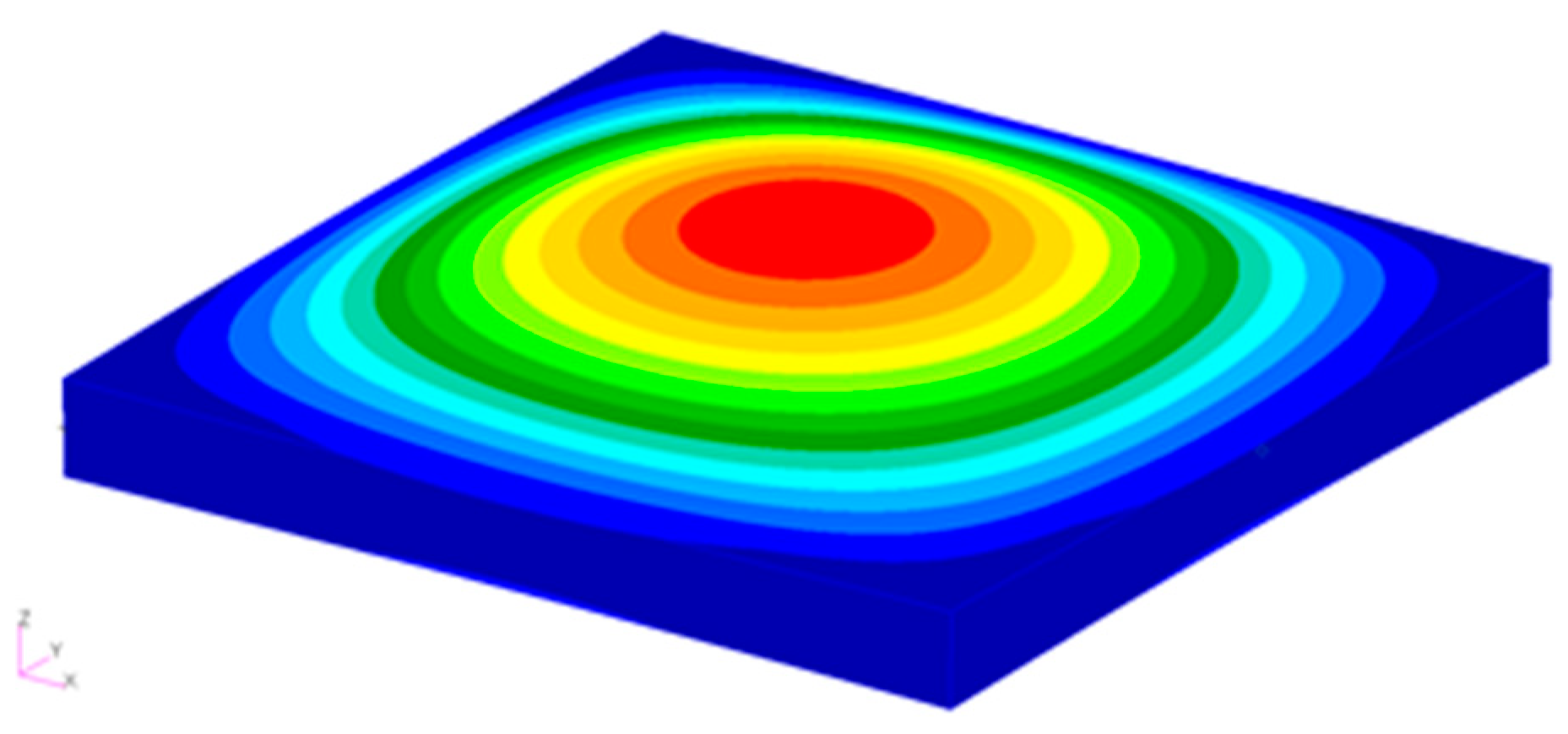
To validate the FGM modeling method in this study, a vibration analysis is conducted for comparison with the FEM. The finite element model is partitioned into 50 sections in the length and width directions, and 10 segments in the thickness direction, resulting in 250,000 solid elements with the simple-supported boundary conditions, as shown in Figure 2. The first-order vibration frequencies, which correspond to the bending modes, are compared between the semianalytical method and the FEM results solved by sol 103 in MSC. Nastran, as shown in Figure 3. Firstly, the stiffness matrix under thermal loading is solved by sol 153. Based on the updated stiffness matrix as a static pre-stress field, the vibration characteristics are solved by sol 103.
Table 2 shows the dimensionless frequencies ( ω ¯ 1 ) of the FG plates, defined in Equation (50) under different temperature fields obtained with the Ritz-based method and FEM at k = 1 and a temperature increase of 30 K, which means that ΔT = 30 K under a uniform temperature field and Tm = 30 K and Tcm = 30 K under a linear and nonlinear temperature fields. In addition, the results under room temperature without the influence of thermal gradient are listed as a reference. The relative errors between the semianalytical method and the finite element method are trivial, thus confirming the accuracy of the proposed approach. Errors arise from the use of the semianalytical method based on the CPT, which neglects the shear effect, while the FEM utilizes three-dimensional solid element modeling to account for this effect. In addition, the semianalytical method involves a continuous theoretical approach in the thickness direction whereby the material properties and individual response quantities vary continuously. Conversely, the FEM provides discrete results and hence does not accurately represent the material properties at that specific location.
ω ¯ 1 = ω 1 a 2 h ( ρ m ( 1 υ 2 ) E m ) 1 2

3.2. Static Aerothermoelastic Analysis

First, the static aerothermoelastic behaviors are analyzed under a uniform temperature field. The first six orders are considered in the Ritz function. The conditions are assumed to be as follows: the flight Mach number is Ma = 5, the dimensionless mass-to-Mach number ratio is μ/Ma = 0.01, and the dimensionless dynamic pressure is λd = 200, the temperature increase is ΔT = 20 K, and the initial angle of attack is α0 = 0.01.
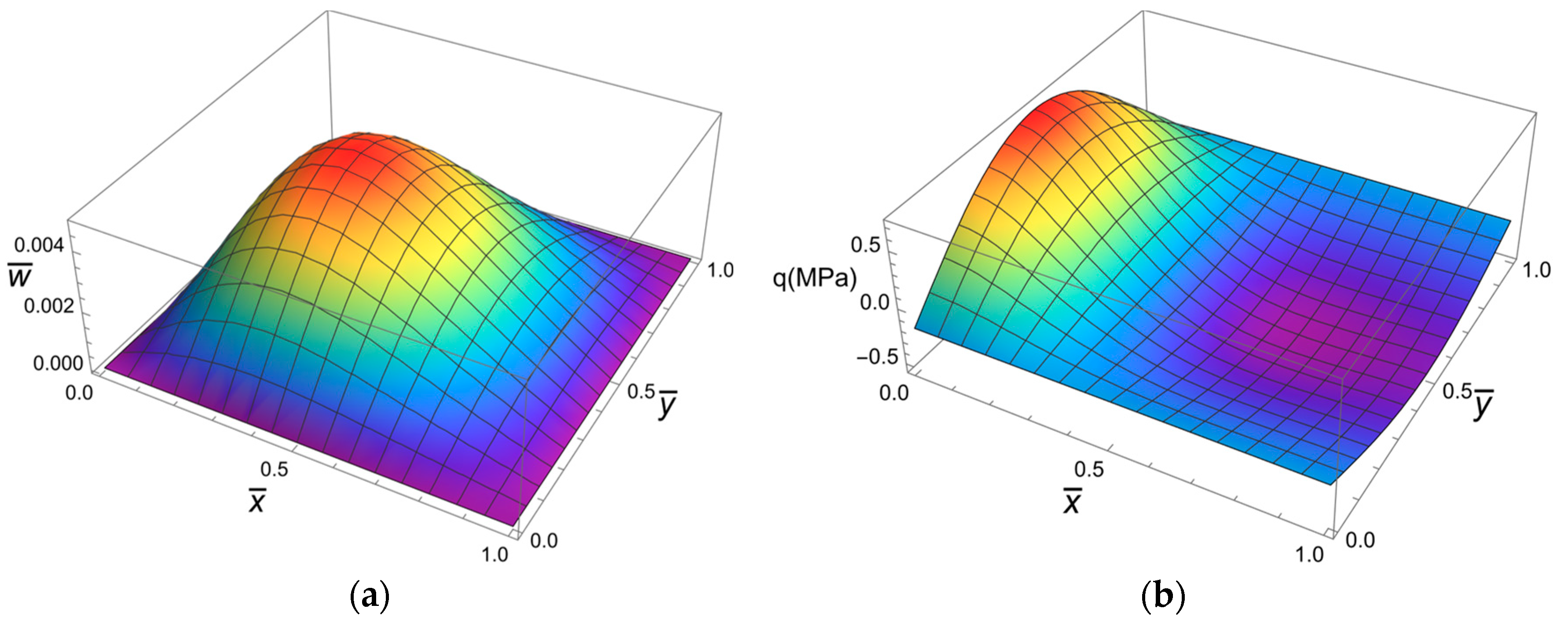
When k = 1, Figure 4 reveal the deformation of the FG plate and the corresponding applied aerodynamic pressures, respectively. The deformation is symmetric perpendicularly to the flow direction and exhibits a half-period of the sinusoidal function, as the first-order deflection function is the only one applied. In the direction of the incoming flow, the first-order coefficient dominates and generates a slight forward tilt of the deformation due to aerodynamic forces, resembling a sinusoidal function. In terms of the aerodynamic distribution on the FG plates, the distribution in the x-direction follows a cosine function law since the spatial correlation term is proportional to the first-order derivative of the de-flection function. The front half of the FG plate is designated the positive pressure zone, while the rear half is the negative pressure zone, and the maximum positive pressure zone occurs at the front end.
Research has revealed that the FG plate response is temperature sensitive, particularly in terms of the variation in the response versus the volume fraction index. Figure 5 shows the variance patterns of the maximum deformation with respect to the volume fraction index at ΔT = 0, 2 K, 4 K, 6 K, 8 K and 20 K. As the temperature increases, the correlation between the maximum deformation and the volume fraction index shifts from a monotonically increasing trend to a monotonically decreasing trend, revealing a highly intricate pattern of change. This is because structural stiffness is associated with mechanical stiffness, which leads to a positive contribution, and thermal stiffness related to the temperature increase, which leads to a reduction in stiffness. As the volume fraction index increases, metals with a lower elastic modulus and coefficient of thermal expansion than those of ceramic become more dominant. Simultaneously, the absolute values of both the mechanical stiffness and the thermal stiffness decrease. As the temperature increases, the reduction influence of the thermal stiffness increases, while the influence of the mechanical stiffness remains constant. Therefore, at lower temperatures, the mechanical stiffness dominates, and the maximum deformation grows with increasing volume fraction index. On the other hand, at higher temperatures, the thermal stiffness takes over, resulting in a decrease in the maximum deformation. Due to the contrasting trends of mechanical stiffness and thermal stiffness with respect to the volume fraction index, which have varying rates of change, the trend with respect to the volume fraction index becomes more intricate when the temperature increases moderately.
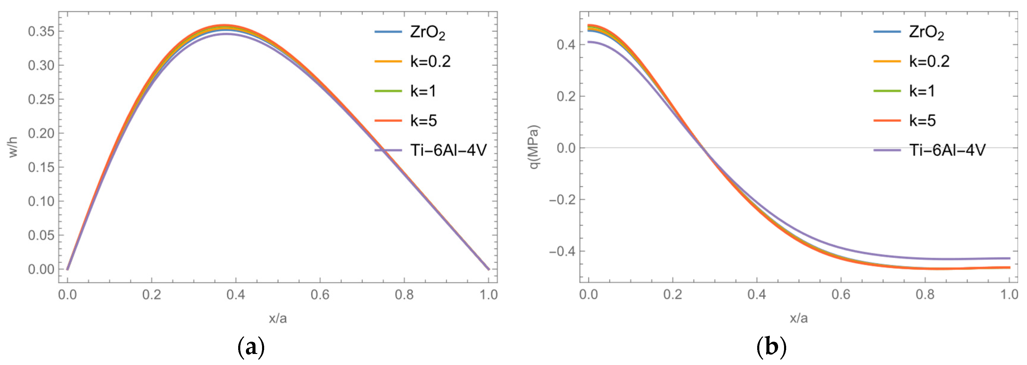
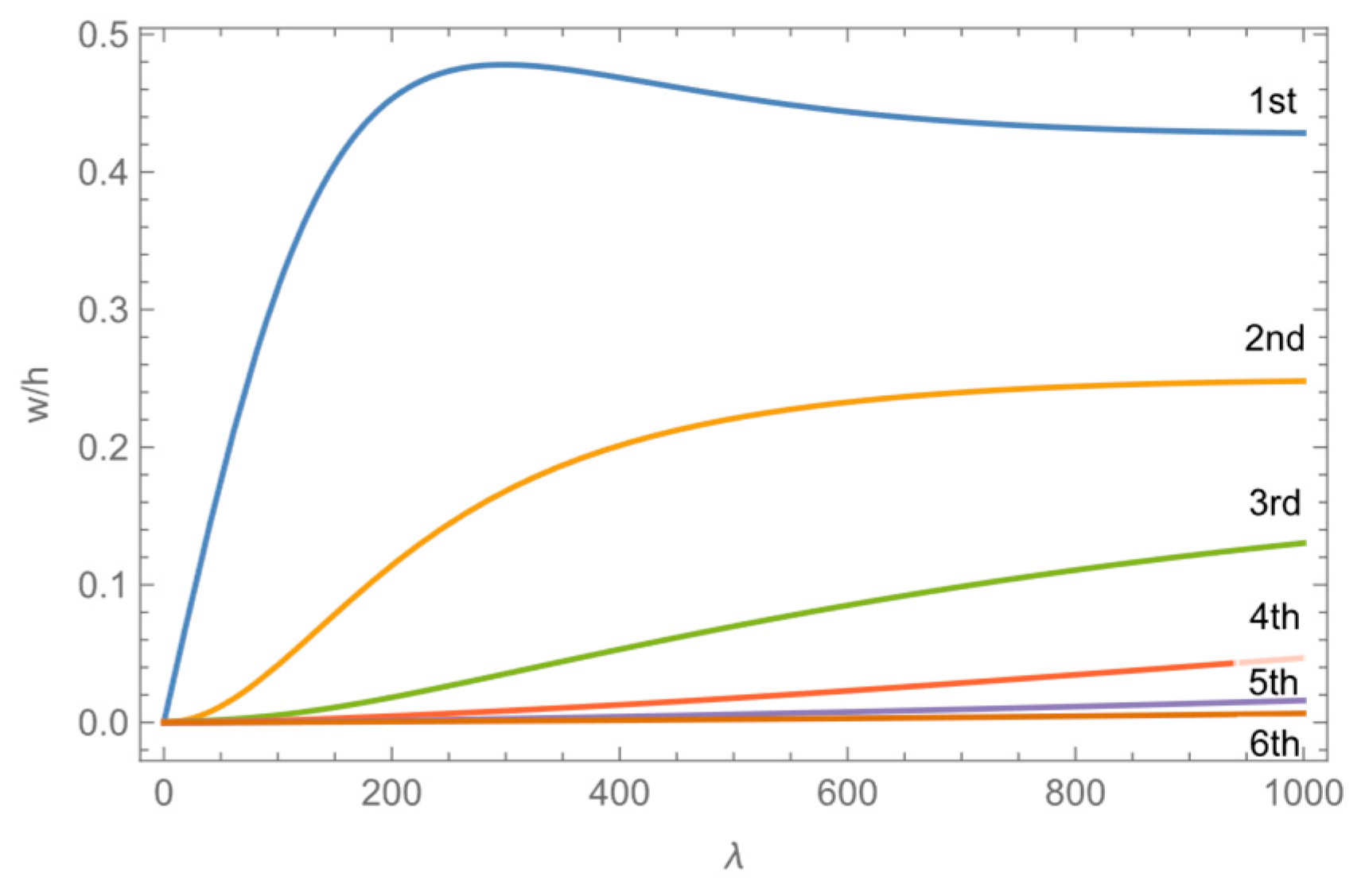
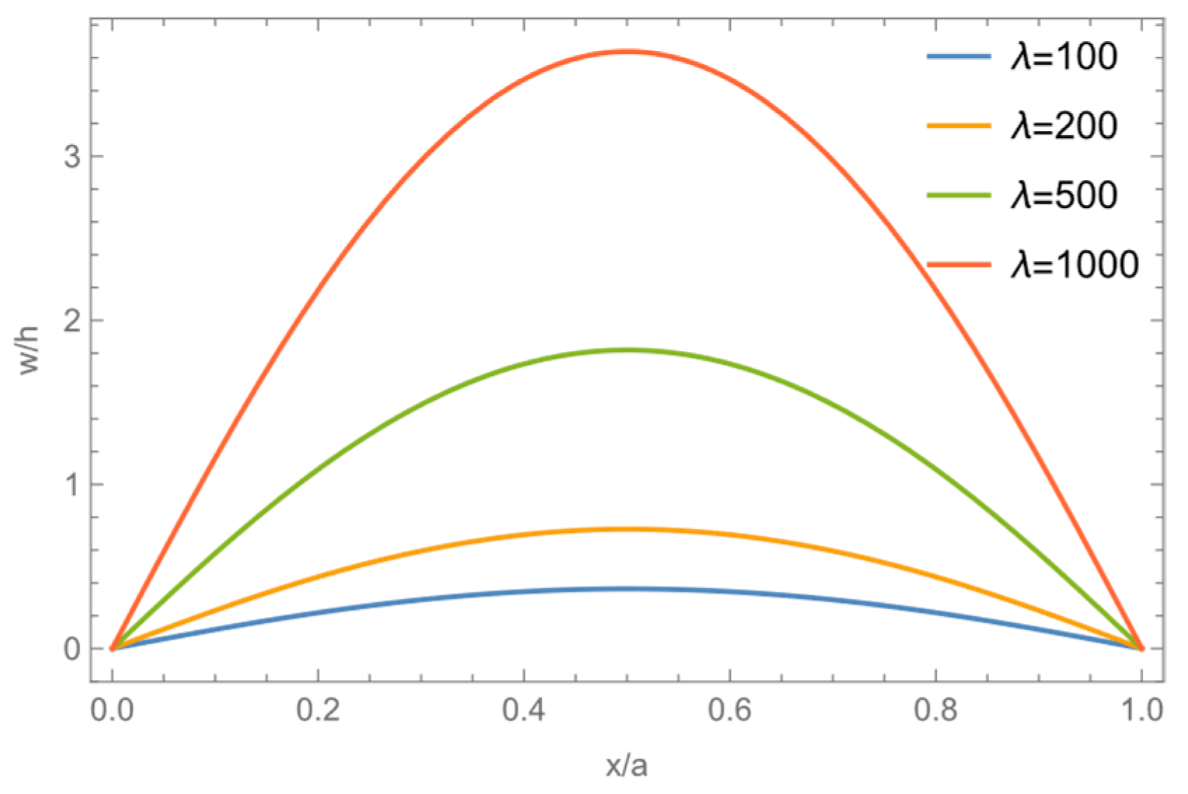
When the temperature increase is 20 K or 2 K, the deformation of the FG plate and the applied aerodynamic pressure in relation to the volume fraction index are illustrated in Figure 6 and Figure 7. The volume fraction index predominantly affects the overall stiffness of the structure. However, the influence does not directly alter the distribution pattern of the aerodynamic force. Additionally, the deformation in the flow direction remains consistent with the prescribed rules. The deformation and aerodynamic force of the FG plate fall between those of the metal and ceramic plates. At a temperature of 20 K, as the volume fraction index increases, the decrease in thermal stiffness is greater than the increase in mechanical stiffness, resulting in an overall stiffer FG plate. This leads to reduced deformation, decreased aerodynamic force due to aeroelastic deformation, and, consequently, a decreased aerodynamic force. When the temperature is 2 K, the overall stiffness increases since the reduction in thermal stiffness is less than the increase in mechanical stiffness, in contrast to the trend observed at ΔT = 20 K. The deformation and aerodynamic force of the FG plate have direct relationships with the dynamic pressure. Figure 8 and Figure 9 depict the relationships between the deformation, aerodynamic force and deflection coefficients at each order and the dynamic pressure. When the dynamic pressure increases from λ = 100 to λ = 1000, the maximum dimensionless deformation shifts from 0.321 to 0.638 as the position of appearance moves forward, from 0.420 to 0.215. Additionally, the peak of the aerodynamic force rapidly increases, appearing at the leading edge. The first-order coefficient initially increases rapidly, reaching a maximum value at a dimensionless pressure of 0.478 before gradually decreasing, while the remaining coefficients increase as the dynamic pressure increases. As the dynamic pressure increases, the energy from the first order slowly spreads to subsequent orders, causing the other order coefficients to gradually increase while the first order becomes less dominant. This results in a gradual change in the deformation and the subjected aerodynamic force pattern, with the first order initially dominating and then spreading to the second and third orders.
The maximum deformation and maximum stress of the FG plate under varying temperature fields, with a volume fraction index of k = 1 and temperature increase of 20 K and 2 K, are outlined in Table 3. The results show that the maximum deformation and maximum stress are the largest under the uniform temperature field, but are the smallest under the nonlinear temperature field. This is because at the same temperature increase, the FG plate experiences the highest internal temperature, the highest thermal stress, the lowest total stiffness, and the largest deformation and stress within the uniform temperature field. Conversely, this effect is associated with the lowest internal temperature and the smallest deformation and stress within the nonlinear temperature field. Considering the temperature-dependent properties, when subjected to a larger temperature increase of 20 K, the coefficient of thermal expansion of the ceramic component decreases more, resulting in less thermal stiffness but higher total stiffness. Conversely, a smaller temperature increase of 2 K causes the coefficient of thermal expansion and elastic modulus of the metal component to increase further, leading to decreased thermal stiffness and lower total stiffness.

3.3. Research on Aeroelastic Effects

Furthermore, this study examines the impact of aeroelastic effects. The investigation is conducted in the absence of aeroelastic effects, i.e., when the aerodynamic force contains only the constant term originating from the angle of attack and not the component caused by deformation. Figure 10, Figure 11 and Figure 12 display the deformation of the structure and its corresponding variations with the volume fraction index and dynamic pressure. The deformation approximates a sinusoidal function and is symmetrically distributed when the aeroelastic effect is not considered due to the constant aerodynamic force on the FG plate. As the dynamic pressure increases, the stringwise deformation increases, while the deformation distribution remains symmetric. With a temperature increase of ΔT = 20 K, the maximum deformation decreases with increasing volume fraction index, but still exceeds that considering aeroelastic effects. Therefore, the aeroelastic effect primarily reduces structural deformation and alters its form to direct the deformation toward the leading edge. In addition, deformations display variations under distinct dynamic pressures, with increased pressures moving the deformation increasingly forward.

4. Numerical Results of Panel Flutter in Thermal Environments

In this section, linear and nonlinear analyses of the panel flutter of FG plates in thermal environments are conducted under a uniform/linear/nonlinear temperature field based on Case 1.

4.1. Linear Analysis

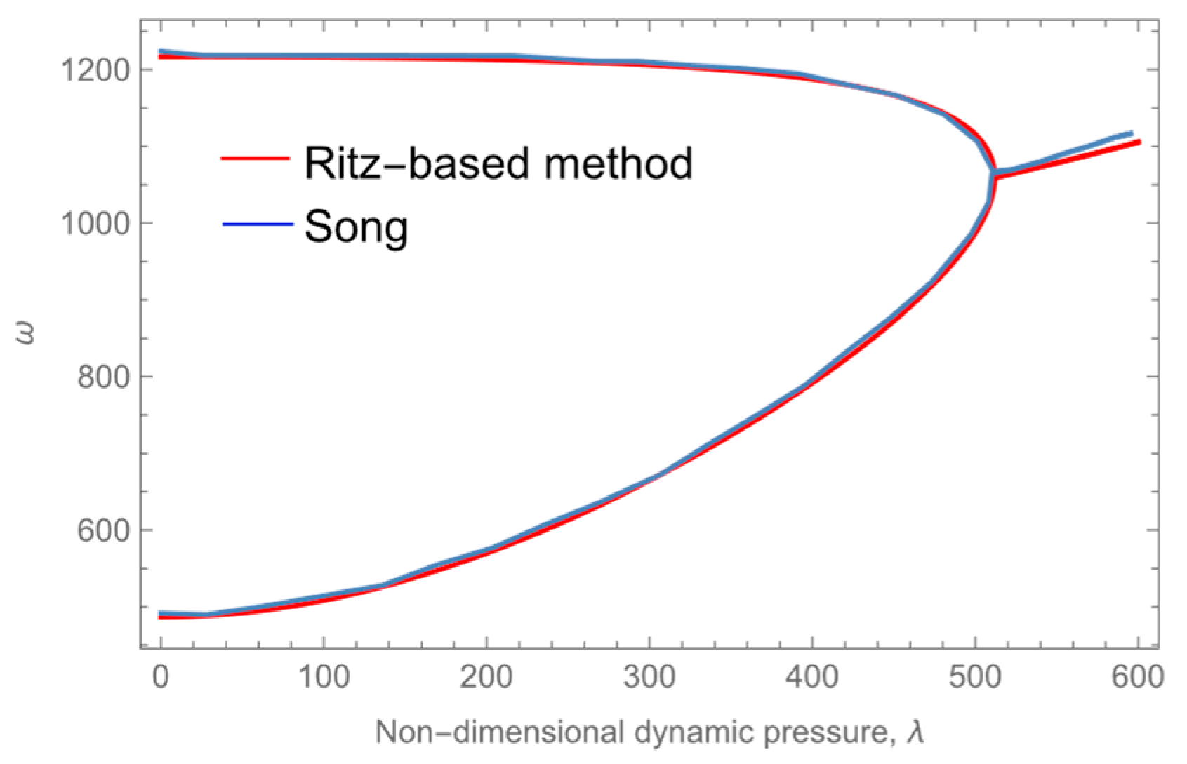
First, the results of the Ritz-based method in this study are compared with those of Song’s method [44] for a metal plate. The relationship between the natural frequencies and dynamic pressure of the plates when k = 0 in Case 1 is depicted in Figure 13. It can be seen that the curves are very close to each other, which verifies the correctness of the method used in this paper.
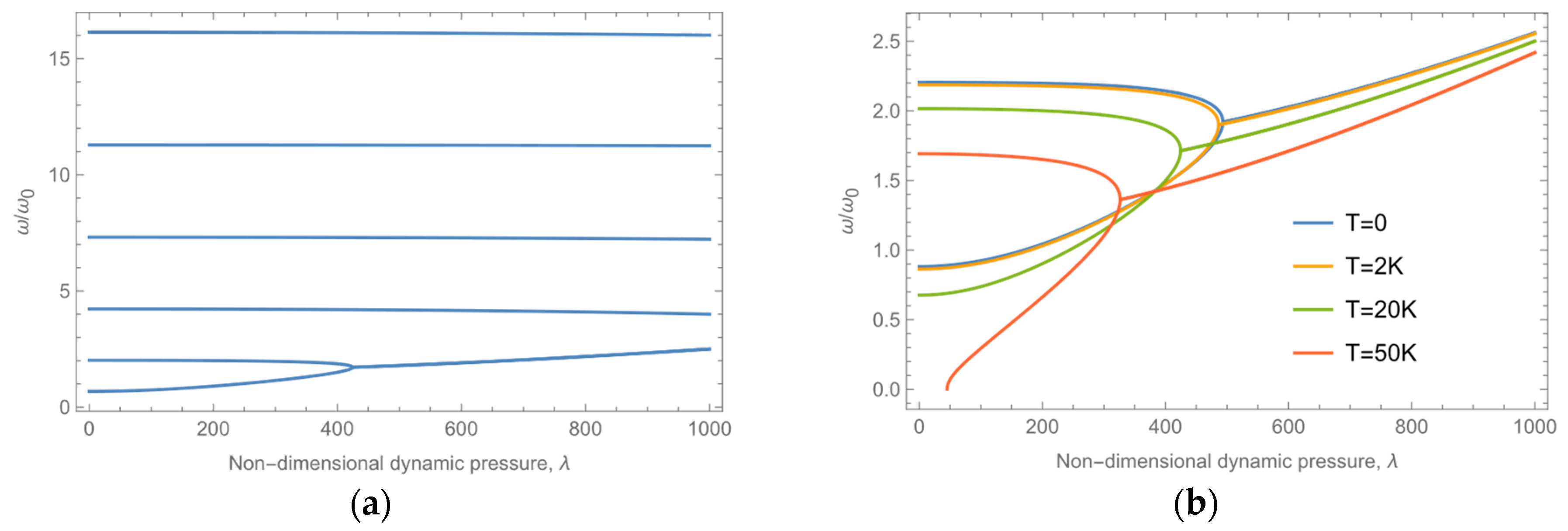
In this section, linear analysis is conducted for the FG plate in Case 1 using the first six Ritz orders. Figure 14a illustrates the relationship between the dynamic pressure and flutter frequency for each order at a Mach number of Ma = 5, a temperature increase of ΔT = 20 K of each order experiences different changes. Low-order frequency changes are more pronounced, while the first-order frequency gradually increases, and the high-order frequency slightly decreases. At a dimensionless dynamic pressure of 424, the first two orders of frequency coincide, and the eigenvalues of the first two orders of the system transform from two real roots into a pair of conjugate complex roots, thus inducing panel flutter. This is due to the mutual coupling between different orders of aerodynamic forces in the spatial correlation term in piston theory. This coupling results in the higher-order term providing additional aerodynamic stiffness for the lower-order term, improving the lower-order natural frequencies. Similarly, the lower-order term weakens the aerodynamic stiffness of the higher-order term. As the dynamic pressure increases, the frequency of the first coupled orders becomes the lowest-order term and increases with increasing dynamic pressure, while the higher-order dynamic pressure decreases with increasing dynamic pressure. The nondimensional frequency can be defined as the ratio of the frequency to the first-order natural frequency of ceramic plates, ω0, as
ω 0 = π 2 ( 1 a 2 + 1 b 2 ) E c h 2 12 ( 1 ν 2 ) ρ c
To examine the flutter characteristics at various temperatures, Figure 14b shows the fluctuations in the frequencies in the first two orders, corresponding to dynamic pressure increases at different temperatures. Furthermore, higher temperatures are shown to have a more notable effect in this regard. The results indicate that as the temperature increases, the overall stiffness of the FG plate decreases, causing a reduction in the frequency and flutter dynamic pressure. Due to the presence of aerodynamic forces, the first-order stiffness increases, allowing the FG plate to regain a stable state within a certain range even after buckling under no aerodynamic loading.
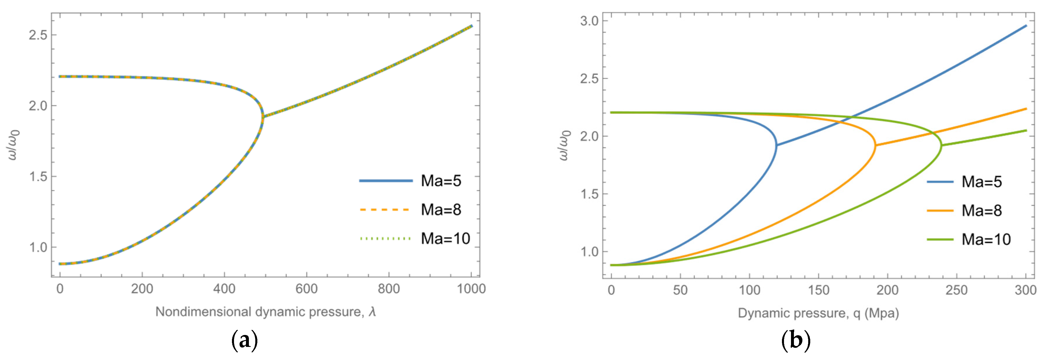
In order to investigate the influence of the Mach number, Figure 15 show the variation of flutter frequencies with the nondimensional dynamic pressure and the actual dynamic pressure under various Mach numbers, respectively. It can be observed that the flutter characteristics are independent of the dimensionless dynamic pressure, as the Mach number is already accounted for in the nondimensionalization, which is also shown in Equation (49). In contrast, the flutter characteristics are dependent of the actual dynamic pressure. The flutter dynamic pressure is higher at the higher Mach number when the dynamic pressure is dimensional.
Table 4 shows the flutter dynamic pressure under various temperature fields. With the same temperature increase, the internal temperature of the uniform temperature field plate is the highest, while the internal temperature of the nonlinear temperature field plate is the lowest and the opposite is true for the flutter dynamic pressure. Additionally, considering the temperature-dependent properties of FG plates, the total stiffness is lower, leading to larger deformations and a lower critical flutter dynamic pressure at lower temperatures.
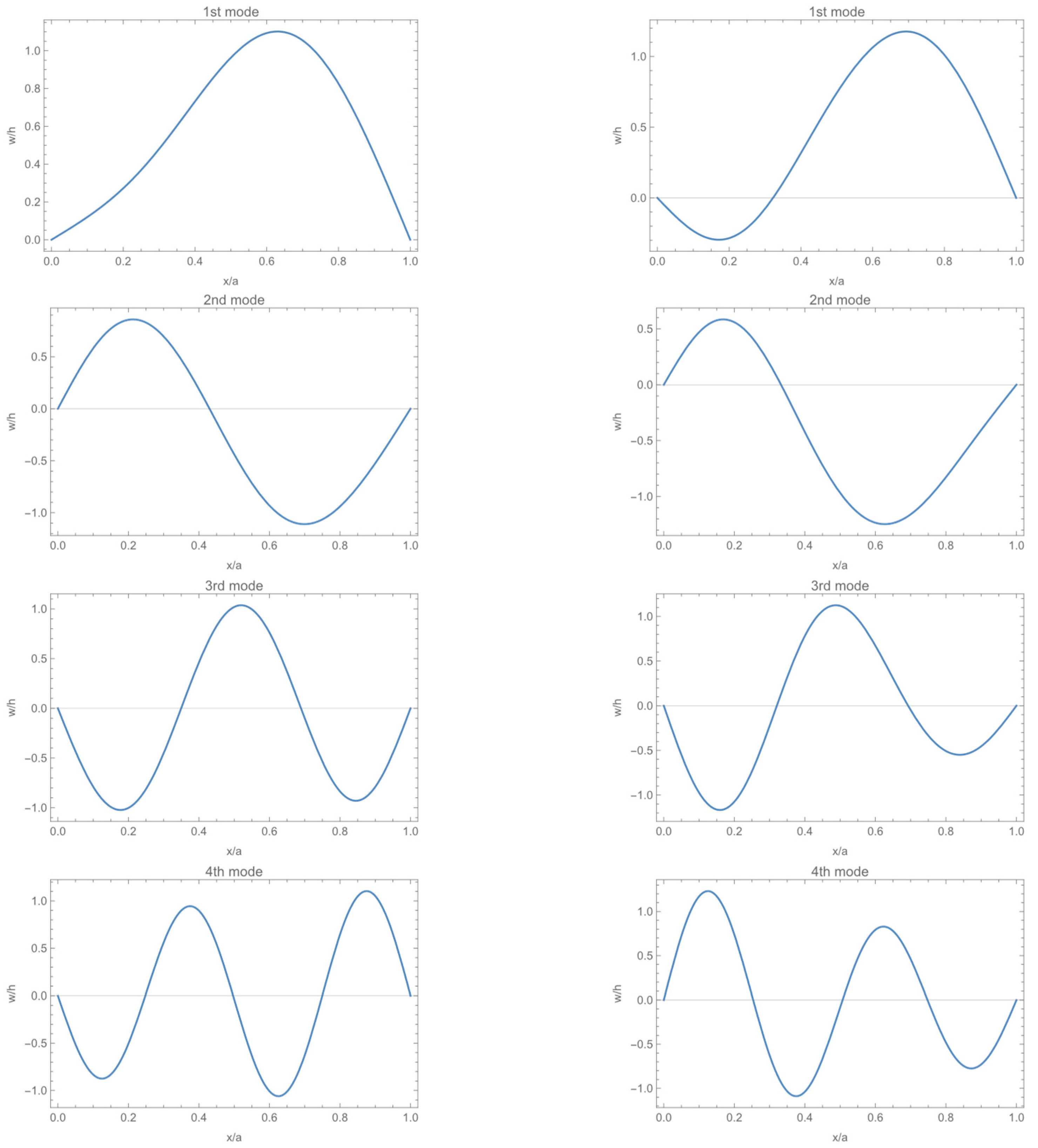
Figure 16 displays the modes of each order for the FG plate at dynamic pressures of λ = 200 (before the flutter boundary) and λ = 424 (near the flutter boundary). The aerodynamic forces lead to distinct modes at varying dynamic pressures. When the dynamic pressure does not reach the flutter boundary, each mode is directly influenced by its respective sinusoidal order, and the other sinusoidal functions have a lesser impact. However, when the dynamic pressure approaches the flutter boundary, the modes of each order exhibit changes compared to when the plate is not near the boundary. Specifically, the first few orders experience more dramatic changes, while the first two modes display almost identical shapes, indicating that they are coupled. This coupling results in the occurrence of flutter.

4.2. Nonlinear Analysis

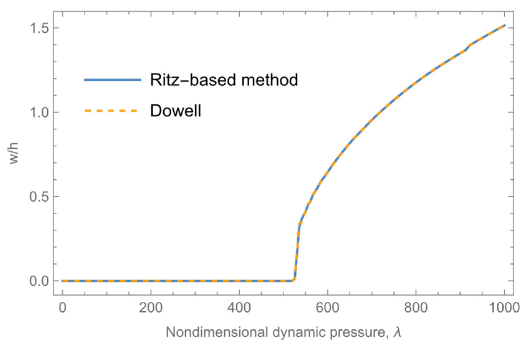
First, the results of the Ritz-based method in this study are compared with those of Dowell’s method [2] at a dimensionless mass-to-Mach number ratio of μ/Ma = 0.01 and Mach number of Ma = 5. The relationship between the limit-cycle amplitudes and dynamic pressure of the ceramic plates when k = 0 in Case 1 is depicted in Figure 17. The results of this study resemble those of Dowell, indicating the accuracy of the method used in this study.
A nonlinear analysis of panel flutter in thermal environments is conducted for the FG plate in Case 1 at a dimensionless mass-to-Mach number ratio of μ/Ma = 0.01, Mach number of Ma = 5 and angle of attack of α0 = 0.01. With the initial condition that all order deflection coefficients have displacement and velocity values of 0, the differential equations described in Equation (48) can be numerically integrated in the time domain to determine various types of response quantities.
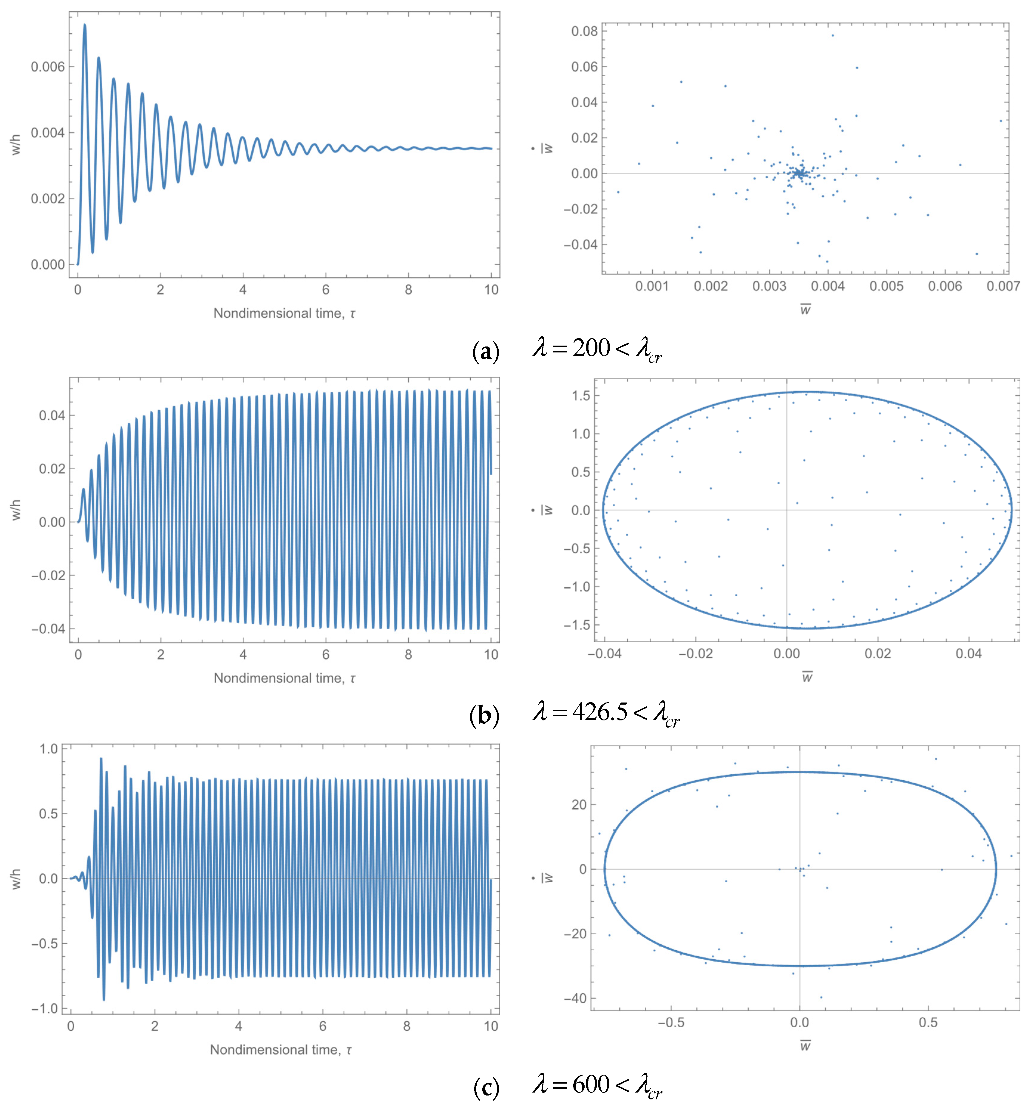
The dynamic responses and phase charts of the FG plate under different dynamic pressures at representative coordinates chosen as x/a = 0.75 and y/b = 0.5 are shown in Figure 18. The time-domain response characteristics vary significantly under various dynamic pressures. When the dynamic pressure is low, the FG plate remains dynamically stable. Initially, the perturbations decrease gradually while the system dissipates the perturbation energy, yielding a finite value. The phase diagram shows the convergence of the displacement and velocity of the representative coordinates toward a single point. As the dynamic pressure increases, the initial perturbation becomes increasingly larger.
However, the system is unable to dissipate the initial perturbation energy. Consequently, the perturbation gradually accumulates and increases, resulting in the displacement and velocity of the representative coordinates converging to those of the limit cycle at λd = 426.5. The system response then moves slowly from the center of the phase diagram to the outside and ultimately reaches the limit cycle. As the pressure increases, the amplitude of the limit cycle also increases because of the geometrically nonlinear effect of the structure. As the deformation becomes larger, the stiffness increases, which restricts further amplitude expansion. The system begins with a slight amplitude vibration near the equilibrium position. The system response swiftly expands from the center of the phase diagram to the limit ring and ultimately converges.
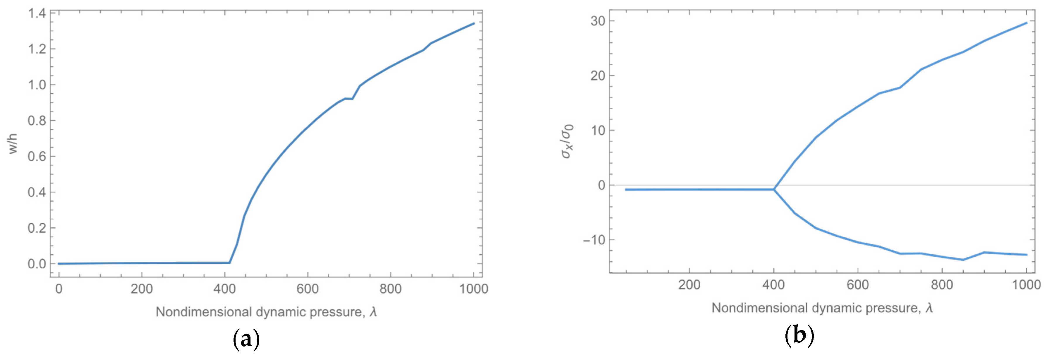
The limit-cycle amplitude for the dynamic pressure is illustrated in Figure 19a. When the critical dynamic pressure is not reached, the maximum deformation is minor, resulting solely from static forces. However, when the critical dynamic pressure is achieved, nonlinear panel flutter occurs due to the mutual influence of aerodynamic forces and the structure, and the limit-cycle amplitude grows rapidly. The relationship between the stress and dynamic pressure is illustrated in Figure 19b. The stresses can be divided into three parts: bending stresses, which are symmetrically related to the neutral surface; membrane stresses, which act on the neutral surface due to geometrical nonlinearities; and thermal stresses due to temperature loading. In bending stresses, the maximum tensile stresses are reached at the top while the minimum compressive stresses are reached at the bottom. On the other hand, in a uniform temperature field, the tensile membrane stresses and compressive thermal stresses are uniform in the FG plates. Both bending and membrane stresses are influenced by deformation, and the geometrically nonlinear effect becomes more prominent in large deformation cases. Prior to reaching the critical dynamic pressure, the stresses remain low due to minimal deformation, which is primarily controlled by thermal stresses. The maximum stresses at the top and bottom of the plate are similar and are both compressive. Once the flutter dynamic pressure is reached, rapid deformation and membrane stress expansion occur. Furthermore, due to the upward direction of the aerodynamic force in most cases, the maximum upward deformation is greater than the maximum downward deformation. Consequently, the absolute value of the maximum tensile stress exceeds that of the compressive stress, with a ratio of approximately 3:1. Therefore, the location of the maximum stress is at x/a = 3/4, y/b = 1/2, and z/h = 1/2. The stress is expressed in a dimensionless form, where
σ 0 = E c ( h / a ) 2 1 ν 2
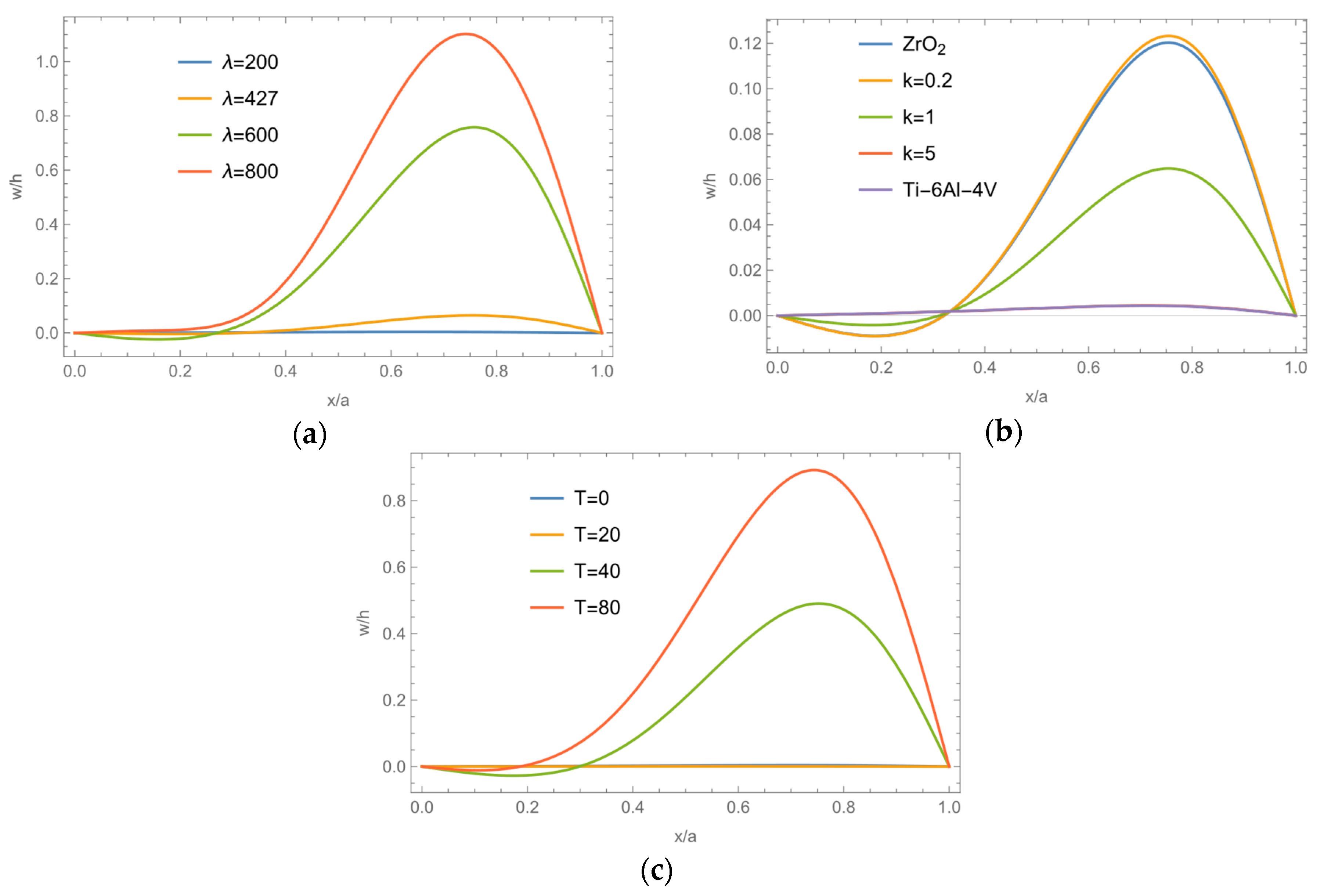
To investigate the relationships between the limit-cycle amplitude and the dynamic pressure, volume fraction index, and temperature increase, the characteristics of nonlinear panel flutter are analyzed based on the basic state at λ = 427, k = 1 and ΔT = 20 K, which is near the critical conditions, as shown in Figure 20. Before reaching the critical dynamic pressure, the FG plate remains dynamically stable with minimal deformation due to static aerodynamic forces. However, after the critical dynamic pressure is reached, the limit-cycle amplitude expands rapidly. The amplitude is minimal near the leading edge, where it is downward, and it increases steadily toward the trailing edge. This is due to the increase in the limit-cycle amplitude, which causes the deformation to move toward the center. As the mechanical properties of the metal and ceramic components are quite similar in this example, the volume fraction index has less influence. However, as the volume fraction index increases and the proportion of the metal component increases, the total stiffness of the FG plate also increases, leading to an increase in the flutter dynamic pressure. The response of the FG plate is not always situated in the center between the metal plates and ceramic plates, such that the maximum deformation of the FG plate at k = 0.2 is slightly greater than that of the ceramic plates. This is because the responses of the plates are impacted by both the mechanical and thermal stiffness terms, which are related to the elastic modulus and thermal strains, respectively. Furthermore, at different volume fraction indexes, the various proportions of ceramic and metal components have different properties following a certain temperature increase, resulting in complex stiffness variations. At low temperatures and given dynamic pressures, the critical dynamic pressure is not reached. However, with an increase in temperature, the stiffness of the FG plate decreases, leading to deteriorated stability. Gradually, the plate becomes dynamically unstable, and the limit-cycle amplitude increases progressively.

5. Discussion

In this study, a semianalytical aerothermoelastic analysis based on the energy method is conducted, encompassing static aerothermoelastic, linear and nonlinear analyses of the panel flutter of functionally graded (FG) plates in thermal environments. The influence of the thermal environment is focused on the thermal stiffness and thermal degradation under different temperature fields. In addition, the impacts of the volume fraction index, temperature increase, and dynamic pressure on the aerothermoelastic behaviors of the FG plates are also investigated. The method can theoretically aid in investigating the influences of different variables and in the efficient analysis and optimization of FG structures.
The results obtained using the semianalytical method in this paper are compared to those obtained using the finite element method and with the results reported in the literature. The comparison reveals a high degree of agreement, which provides evidence of the effectiveness of the method presented in this paper. However, due to the limitations of the conditions under which the work was conducted, the results have not been verified experimentally. Consequently, further verification of the method can be achieved through the ground vibration test of a FG plate and other methods.

6. Conclusions

(1)
The paper presents a semianalytical analysis method for solving the unknown deflection coefficients to acquire the explicit solutions for static areothermoelastic responses and to solve the eigenvalues for the coefficient matrix and a system of ordinary differential equations in linear and nonlinear analysis for panel flutter, respectively.
(2)
According to the static aerothermoelastic analysis, the aeroelastic effect reduces the maximum deformation and the peak of the applied aerodynamic force. The coupling effect between the orders of aerodynamic forces shifts the deformation of the structure toward the leading edge and reduces the maximum deformation.
(3)
FG plates exhibit sensitivity to thermal loading, particularly concerning the correlation between stiffness and the volume fraction index. It is important to note that the ratio of mechanical stiffness to thermal stiffness was not consistent at different temperatures, as both of these stiffnesses progressively decrease with an increase in the volume fraction index despite contributing to the total stiffness in opposite directions. At lower temperatures, mechanical stiffness prevails, resulting in a decrease in total stiffness with an increase in the volume fraction index.
(4)
The general form of arbitrary temperature fields proposed in this paper can deal with complex thermal loads and provides a foundation for practical aerothermoelastic engineering problems. With the same temperature increase, the internal temperature of the uniform temperature field plate is the highest, while the internal temperature of the nonlinear temperature field plate is the lowest.

Author Contributions

Conceptualization, C.L., Z.W., X.W. and C.Y.; methodology, C.L.; software, C.L. and K.L.; validation, C.L.; formal analysis, C.L.; investigation, C.L.; resources, C.L.; data curation, C.L.; writing—original draft preparation, C.L. and K.L.; writing—review and editing, Z.W. and X.W.; visualization, C.L.; supervision, X.W. and Z.W.; project administration, Z.W.; funding acquisition, C.Y. All authors have read and agreed to the published version of the manuscript.

Funding

This research was funded by the Aeronautical Science Foundation of China, No.: 2022Z012051001.

Data Availability Statement

The original contributions presented in the study are included in the article, further inquiries can be directed to the corresponding author.

Conflicts of Interest

The authors declare no conflicts of interest.

Correction Statement

This article has been republished with a minor correction to resolve spelling and grammatical errors. This change does not affect the scientific content of the article.

Appendix A

The general form of thermal forces under arbitrary temperature fields can be acquired as
N T = h 1 ν ( α m E m i = 0 N c i i + 1 + α cm E cm i = 0 N c i i + 1 + 2 k + ( α m E cm + α cm E m ) i = 0 N c i i + 1 + k )
When the properties of FGM are temperature-dependent, the thermal forces become more complex in form, as shown in Equation (A2) where Tij (i = 1, 2, 3, j = 0, 1, 2) denotes the intermediate coefficients, as shown in Equation (A3).
N T = h 1 ν ( i = 0 N c i ( T 10 i + 1 + T 11 i + k + 1 + T 12 i + 2 k + 1 ) + i = 0 N j = 0 N c i c j ( T 20 i + j + 1 + T 21 i + j + k + 1 + T 22 i + j + 2 k + 1 ) + i = 0 N j = 0 N l = 0 N c i c j c l ( T 30 i + j + l + 1 + T 31 i + j + l + k + 1 + T 32 i + j + l + 2 k + 1 ) )
T 10 = α m 0 E m 0 ; T 11 = α m 0 E c 0 + α c 0 E m 0 2 α m 0 E m 0 ; T 12 = α c 0 E c 0 α m 0 E c 0 α c 0 E m 0 + α m 0 E m 0 ; T 20 = α m 0 α m 1 E m 0 + α m 0 E m 0 E m 1 ; T 21 = α m 0 α m 1 E c 0 + α m 0 E c 0 E c 1 + α c 0 α c 1 E m 0 2 α m 0 α m 1 E m 0 + α c 0 E m 0 E m 1 2 α m 0 E m 0 E m 1 ; T 22 = α c 0 α c 1 E c 0 α m 0 α m 1 E c 0 + α c 0 E c 0 E c 1 α m 0 E c 0 E c 1 α c 0 α c 1 E m 0 + α m 0 α m 1 E m 0 α c 0 E m 0 E m 1 + α m 0 E m 0 E m 1 ; T 30 = α m 0 α m 1 E m 0 E m 1 ; T 31 = α m 0 α m 1 E c 0 E c 1 + α c 0 α c 1 E m 0 E m 1 2 α m 0 α m 1 E m 0 E m 1 ; T 32 = α c 0 α c 1 E c 0 E c 1 α m 0 α m 1 E c 0 E c 1 α c 0 α c 1 E m 0 E m 1 + α m 0 α m 1 E m 0 E m 1 ;
The integration coefficients of the governing of nonlinear panel flutter are shown in Equation (A4)
A = m m 2 + ν ( a / b ) 2 1 ν 2 c w m 2 B = m ( a / b ) 2 + ν m 2 1 ν 2 c w m 2 C = m s r c w m c w s c w r r 2 ( γ ( s + m ) ( r n ) γ ( s + m ) ( r + n ) ) m ( s m ) [ ( s + m ) 2 + 4 ( a / b ) 2 ] 2 + m s r c w m c w s c w r r 2 ( γ ( s m ) ( r n ) γ ( s m ) ( r + n ) ) m ( s + m ) [ ( s m ) 2 + 4 ( a / b ) 2 ] 2 γ ( p ) ( q ) = { 2 , p = q = 0 1 , p = q 0 1 , p = q 0 0 , p q & p q D = m s r c w m c w s c w r r ( β ( s + m ) ( r + n ) + β ( s + m ) ( n r ) ) m ( s m ) ( s + m ) [ ( s + m ) 2 + 4 ( a / b ) 2 ] 2 + m s r c w m c w s c w r r ( β ( s m ) ( r + n ) + β ( s m ) ( n r ) ) m ( s + m ) ( s m ) [ ( s m ) 2 + 4 ( a / b ) 2 ] 2 β ( p ) ( q ) = { 1 , p = q 0 1 , p = q 0 0 E = m s r c w m c w s c w r ( γ ( s + m ) ( r n ) γ ( s + m ) ( r + n ) ) m ( s m ) ( s + m ) 2 [ ( s + m ) 2 + 4 ( a / b ) 2 ] 2 + m s r c w m c w s c w r ( γ ( s m ) ( r n ) γ ( s m ) ( r + n ) ) m ( s + m ) ( s m ) 2 [ ( s m ) 2 + 4 ( a / b ) 2 ] 2 F = m s r c w m c w s c w r ( γ ( s + m ) ( r n ) γ ( s + m ) ( r + n ) ) m s + m + m s m r c w m c w s c w r ( γ ( s m ) ( r n ) γ ( s m ) ( r + n ) ) m s m
Moreover, the position of the physical neutral surface differs from the one not concerning the temperature-dependent elastic modulus of FGM, which can be expressed as
z 0 = E m 0 2 + E c 0 E m 0 k + 2 + i = 0 N E m 0 E m 1 c i i k + 2 + ( E c 0 E c 1 E m 0 E m 1 ) c i ( i + 1 ) k + 2 E m 0 + E c 0 E m 0 k + 1 + i = 0 N E m 0 E m 1 c i i k + 1 + ( E c 0 E c 1 E m 0 E m 1 ) c i ( i + 1 ) k + 1

References

  1. Hedgepeth, J.M. Flutter of Rectangular Simply Supported Panels at High Supersonic Speeds. J. Aeronaut. Sci. 1957, 24, 563–573. [Google Scholar] [CrossRef]
  2. Dowell, E.H. Nonlinear oscillations of a fluttering plate. AIAA J. 1966, 4, 1267–1275. [Google Scholar] [CrossRef]
  3. Xue, D.Y.; Mei, C. Finite element nonlinear panel flutter with arbitrary temperatures in supersonic flow. AIAA J. 1993, 31, 154–162. [Google Scholar] [CrossRef]
  4. Guo, X.; Mei, C. Application of aeroelastic modes on nonlinear supersonic panel flutter at elevated temperatures. Comput. Struct. 2006, 84, 1619–1628. [Google Scholar] [CrossRef]
  5. McNamara, J.J.; Friedmann, P.P. Aeroelastic and Aerothermoelastic Analysis in Hypersonic Flow: Past, Present, and Future. AIAA J. 2011, 49, 1089–1122. [Google Scholar] [CrossRef]
  6. Zhou, K.; Su, J.; Hua, H. Aero-thermo-elastic flutter analysis of supersonic moderately thick orthotropic plates with general boundary conditions. Int. J. Mech. Sci. 2018, 141, 46–57. [Google Scholar] [CrossRef]
  7. Quan, E.; Xu, M.; Yao, W.; Cheng, X. Analysis of the post-flutter aerothermoelastic characteristics of hypersonic skin panels using a CFD-based approach. Aerosp. Sci. Technol. 2021, 118, 107076. [Google Scholar] [CrossRef]
  8. Song, Z.; Chen, Y.; Li, Z.; Sha, J.; Li, F. Axially functionally graded beams and panels in supersonic airflow and their excellent capability for passive flutter suppression. Aerosp. Sci. Technol. 2019, 92, 668–675. [Google Scholar] [CrossRef]
  9. Wei, J.; Song, Z.; Li, F. Superior aeroelastic behaviors of axially functional graded cylindrical shells in supersonic airflow. J. Fluids Struct. 2020, 96, 103027. [Google Scholar] [CrossRef]
  10. Muc, A.; Flis, J. Flutter characteristics and free vibrations of rectangular functionally graded porous plates. Compos. Struct. 2020, 261, 113301. [Google Scholar] [CrossRef]
  11. Guo, H.; Żur, K.K.; Ouyang, X. New insights into the nonlinear stability of nanocomposite cylindrical panels under aero-thermal loads. Compos. Struct. 2023, 303, 116231. [Google Scholar] [CrossRef]
  12. Zhou, X.; Wang, Y.; Zhang, W. Vibration and flutter characteristics of GPL-reinforced functionally graded porous cylindrical panels subjected to supersonic flow. Acta Astronaut. 2021, 183, 89–100. [Google Scholar] [CrossRef]
  13. Ganapathi, M.; Aditya, S.; Shubhendu, S.; Polit, O.; Zineb, T.B. Nonlinear supersonic flutter study of porous 2D curved panels including graphene platelets reinforcement effect using trigonometric shear deformable finite element. Int. J. Non-Linear Mech. 2020, 125, 103543. [Google Scholar] [CrossRef]
  14. Khalafi, V.; Fazilati, J. Panel flutter analysis of cracked functionally graded plates in yawed supersonic flow with thermal effects. Appl. Math. Model. 2022, 101, 259–275. [Google Scholar] [CrossRef]
  15. Farsadi, T.; Rahmanian, M.; Kurtaran, H. Nonlinear stability of multilayered graphene platelet-reinforced functionally graded wing-like plates. Acta Mech. 2022, 233, 3233–3252. [Google Scholar] [CrossRef]
  16. Chen, J.; Han, R.; Liu, D.; Zhang, W. Active Flutter Suppression and Aeroelastic Response of Functionally Graded Multilayer Graphene Nanoplatelet Reinforced Plates with Piezoelectric Patch. Appl. Sci. 2022, 12, 1244. [Google Scholar] [CrossRef]
  17. Abbaslou, M.; Saidi, A.R.; Bahaadini, R. Vibration and dynamic instability analyses of functionally graded porous doubly curved panels with piezoelectric layers in supersonic airflow. Acta Mech. 2023, 234, 6131–6167. [Google Scholar] [CrossRef]
  18. Mahmoudkhani, S. Aerothermoelastic analysis of imperfect FG cylindrical shells in supersonic flow. Compos. Struct. 2019, 225, 111160. [Google Scholar] [CrossRef]
  19. Zhong, R.; Qin, B.; Wang, Q.; Shao, W.; Shuai, C. Investigation on flutter instability of magnetic-electric-thermo-elastic functionally graded plates in the supersonic airflow with any yawed angle. Int. J. Mech. Sci. 2021, 198, 106356. [Google Scholar] [CrossRef]
  20. Guo, H.; Li, M.; Żur, K.K.; Yuan, J.; Wu, X. Flutter of carbon-based nanohybrid composite panels. Thin-Walled Struct. 2023, 188, 110828. [Google Scholar] [CrossRef]
  21. Zhong, S.; Jin, G.; Ye, T.; Zhang, Q. Supersonic flutter analysis of variable thickness blades in thermal environment by using isogeometric approach. Thin-Walled Struct. 2022, 172, 108844. [Google Scholar] [CrossRef]
  22. Akbari, H.; Azadi, M.; Fahham, H. Flutter prediction of cylindrical sandwich panels with saturated porous core under supersonic yawed flow. Proc. Inst. Mech. Eng. Part C J. Mech. Eng. Sci. 2020, 235, 2968–2984. [Google Scholar] [CrossRef]
  23. Hao, Y.X.; Zhang, W.; Li, S.B.; Zhang, J.H. Nonlinear Vibrations of FGM Cylindrical Panel with Simply Supported Edges in Air Flow. Int. J. Aerosp. Eng. 2015, 2015, 246352. [Google Scholar] [CrossRef]
  24. Swain, P.K.; Adhikari, B.; Maiti, D.K.; Singh, B.N. Aeroelastic analysis of CNT reinforced functionally graded laminated composite plates with damage under subsonic regime. Compos. Struct. 2019, 222, 110916. [Google Scholar] [CrossRef]
  25. Zhou, K.; Huang, X.; Tian, J.; Hua, H. Vibration and flutter analysis of supersonic porous functionally graded material plates with temperature gradient and resting on elastic foundation. Compos. Struct. 2018, 204, 63–79. [Google Scholar] [CrossRef]
  26. Guo, J.; Qin, Z.; Zhang, Y. Nonlinear aerodynamic analysis of functional graded plates using an HSDT-based isogeometric approach. Thin-Walled Struct. 2023, 186, 110658. [Google Scholar] [CrossRef]
  27. Aditya, S.; Haboussi, M.; Shubhendu, S.; Ganapathi, M.; Polit, O. Supersonic flutter study of porous 2D curved panels reinforced with graphene platelets using an accurate shear deformable finite element procedure. Compos. Struct. 2020, 241, 112058. [Google Scholar] [CrossRef]
  28. Reddy, J.N.; Wang, C.M. An overview of the relationships between solutions of the classical and shear deformation plate theories. Compos. Sci. Technol. 2000, 60, 2327–2335. [Google Scholar] [CrossRef]
  29. Ganapathi, M.; Prakash, T.; Singha, M.K. Nonlinear Stability of Functionally Graded Plates Subjected to Aero-thermo-mechanical Loads. In Proceedings of the IUTAM Symposium on Multi-Functional Material Structures and Systems, Indian Inst Sci, Bangalore, India, 10–12 December 2010; pp. 25–33. [Google Scholar]
  30. Xia, W.; Zhao, X.; Li, D.; Shen, S. Nonlinear flutter response of pre-heated functionally graded panels. Int. J. Comput. Mater. Sci. Eng. 2018, 7, 1850012. [Google Scholar] [CrossRef]
  31. Navazi, H.M.; Haddadpour, H. Parameter Study of Nonlinear Aero-Thermoelastic Behaviour of Functionally Graded Plates. Int. J. Struct. Stab. Dyn. 2009, 9, 285–305. [Google Scholar] [CrossRef]
  32. Navazi, H.M.; Haddadpour, H. Aero-thermoelastic stability of functionally graded plates. Compos. Struct. 2007, 80, 580–587. [Google Scholar] [CrossRef]
  33. Sator, L.; Sladek, V.; Sladek, J. A Strong Form Meshless Method for the Solution of FGM Plates. Aerospace 2022, 9, 425. [Google Scholar] [CrossRef]
  34. Shahverdi, H.; Khalafi, V.; Noori, S. Aerothermoelastic Analysis of Functionally Graded Plates Using Generalized Differential Quadrature Method. Lat. Am. J. Solids Struct. 2016, 13, 796–818. [Google Scholar] [CrossRef]
  35. Fazilati, J.; Khalafi, V.; Shahverdi, H. Three-dimensional aero-thermo-elasticity analysis of functionally graded cylindrical shell panels. Proc. Inst. Mech. Eng. Part G J. Aerosp. Eng. 2018, 233, 1715–1727. [Google Scholar] [CrossRef]
  36. Praveen, G.N.; Reddy, J.N. Nonlinear transient thermoelastic analysis of functionally graded ceramic-metal plates. Int. J. Solids Struct. 1998, 35, 4457–4476. [Google Scholar] [CrossRef]
  37. Ibrahim, H.H.; Tawfik, M.; Al-Ajmi, M. Non-linear panel flutter for temperature-dependent functionally graded material panels. Comput. Mech. 2008, 41, 325–334. [Google Scholar] [CrossRef]
  38. Ibrahim, H.H.; Tawfik, M.; Al-Ajmi, M. Thermal buckling and Nonlinear flutter Behavior of functionally graded material panels. J. Aircr. 2007, 44, 1610–1618. [Google Scholar] [CrossRef]
  39. Ibrahim, H.H.; Yoo, H.H.; Lee, K.-S. Supersonic Flutter of Functionally Graded Panels Subject to Acoustic and Thermal Loads. J. Aircr. 2009, 46, 593–600. [Google Scholar] [CrossRef]
  40. Su, Z.; Wang, L.; Sun, K.; Wang, D. Vibration characteristic and flutter analysis of elastically restrained stiffened functionally graded plates in thermal environment. Int. J. Mech. Sci. 2019, 157, 872–884. [Google Scholar] [CrossRef]
  41. Lee, C.-Y.; Kim, J.-H. Thermal post-buckling and snap-through instabilities of FGM panels in hypersonic flows. Aerosp. Sci. Technol. 2013, 30, 175–182. [Google Scholar] [CrossRef]
  42. Zhang, D.-G.; Zhou, Y.-H. A theoretical analysis of FGM thin plates based on physical neutral surface. Comput. Mater. Sci. 2008, 44, 716–720. [Google Scholar] [CrossRef]
  43. Li, C.; Wan, Z.; Wang, X.; Yang, C.; Li, K. Analytical research for buckling of metal-ceramic functionally graded plates in thermal environments. J. Beijing Univ. Aeronaut. Astronaut. 2024, preprints. [Google Scholar]
  44. Song, Z.-G.; Li, F.-M. Investigations on the flutter properties of supersonic panels with different boundary conditions. Int. J. Dyn. Control. 2013, 2, 346–353. [Google Scholar] [CrossRef]
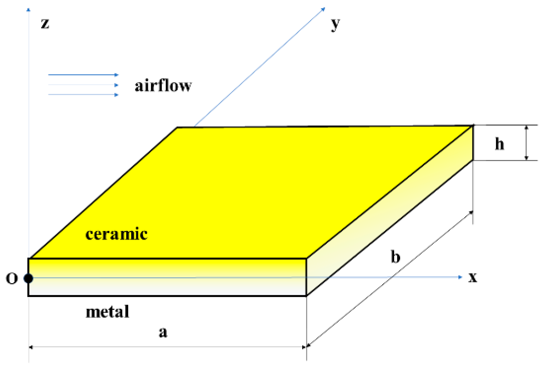
Figure 1. Coordinate system and geometry of the FG plates.
Aerospace 11 00572 g001
Figure 2. Finite element model of the FG plates in Case 1.
Aerospace 11 00572 g002
Figure 3. The first-order mode of the FG plates in Case 1 solved by FEM.
Aerospace 11 00572 g003
Figure 4. The static aerothermoelstic responses of FG plates under a uniform field: (a) static aerothermoelastic deformation; (b) aerodynamic pressure.
Aerospace 11 00572 g004
Figure 5. Maximum deformation of the FG plates vs. the volume fraction index at different temperatures.
Aerospace 11 00572 g005
Figure 6. Static aerothermoelastic responses of the FG plate vs. nondimensional length with different volume fraction indexes (ΔT = 20 K): (a) deformation; (b) applied aerodynamic pressure.
Aerospace 11 00572 g006
Figure 7. Static aerothermoelastic responses of the FG plate vs. nondimensional length with different volume fraction indexes (ΔT = 2 K): (a) deformation; (b) applied aerodynamic pressure.
Aerospace 11 00572 g007
Figure 8. Static aerothermoelastic responses of the FG plate under different dynamic pressures: (a) dimensionless deformation; (b) applied aerodynamic pressure.
Aerospace 11 00572 g008
Figure 9. Deflection coefficients vs. dynamic pressure.
Aerospace 11 00572 g009
Figure 10. Deformation of an FG plate without aeroelastic effects.
Aerospace 11 00572 g010
Figure 11. Dimensionless deformation of an FG plate under different dynamic pressures without aeroelastic effects.
Aerospace 11 00572 g011
Figure 12. Comparison of maximum deformation vs. the volume fraction index with and without aeroelastic effects.
Aerospace 11 00572 g012
Figure 13. Comparison of natural frequencies between the Ritz-based method in this study and Song’s method.
Aerospace 11 00572 g013
Figure 14. Flutter frequencies vs. nondimensional dynamic pressure: (a) the first six orders at ΔT = 20 K; (b) the first two orders at different temperature increases.
Aerospace 11 00572 g014
Figure 15. The variation of flutter frequency under different Mach number: (a) with the nondimensional dynamic pressure; (b) with the dynamic pressure.
Aerospace 11 00572 g015
Figure 16. Aeroelastic modes of the FG plate at dynamic pressures of λ = 200 and λ = 424.
Aerospace 11 00572 g016aAerospace 11 00572 g016b
Figure 17. Comparison of limit-cycle amplitudes between the Ritz-based method in this study and Dowell’s method.
Aerospace 11 00572 g017
Figure 18. Dynamic responses and phase diagrams of the FG plate at representative coordinates.
Aerospace 11 00572 g018
Figure 19. Different variables of the FG plate at representative coordinates with nondimensional dynamic pressure: (a) nondimensional limit-cycle amplitude; (b) nondimensional stresses.
Aerospace 11 00572 g019
Figure 20. Deformations of the FG plate at representative coordinates under different cases: (a) different nondimensional dynamic pressure; (b) different volume fraction indexes; (c) different temperature increases.
Aerospace 11 00572 g020
Table 1. Material properties of FGM.
MaterialP0P1
E (Pa)Ti-6Al-4V122.70 × 109−4.605 × 10⁻⁴
ZrO2132.20 × 109−3.805 × 10⁻⁴
αTi-6Al-4V7.4300 × 10−67.483 × 10⁻⁴
ZrO213.300 × 10−6−1.421 × 10⁻³
ρ (kg/m3)Ti-6Al-4V44290
ZrO230000
λ (W/(m·K))Ti-6Al-4V7.820
ZrO21.80
Table 2. Comparison of dimensionless first-order frequencies ( ω ¯ 1 ) under different temperature fields determined by the semianalytical method and FEM.
The Type of Temperature FieldResults of the
Semianalytical Method
Results of FEMRelative Errors
Room temperature6.339996.289840.80%
Uniform (temperature-independent)3.924604.08109 −3.83%
Uniform (temperature-independent)3.960674.10907 −3.61%
Linear (temperature-dependent)5.145835.19792 −1.00%
Linear (temperature-independent)5.163775.20979 −0.88%
Nonlinear (temperature-independent)5.404865.45582 −0.93%
Nonlinear (temperature-independent)5.415055.46070 −0.84%
Table 3. Static aerothermoelastic responses under various temperature fields.
The Type of the Temperature FieldΔT = 20 KΔT = 2 K
w max / h σ max ( MPa ) w max / h σ max ( MPa )
Uniform (temperature-independent)0.488425234.9520.357481191.747
Uniform (temperature-dependent)0.487631233.6300.357658191.772
Linear (temperature-independent)0.414324184.3040.352639188.579
Linear (temperature-dependent)0.413889182.9160.352719188.538
Nonlinear (temperature-independent)0.399063174.0640.351463187.811
Nonlinear (temperature-dependent)0.398896172.8350.351532187.759
Table 4. Flutter dynamic pressure under various temperature fields.
The Type of the Temperature FieldFlutter Dynamic Pressure
Uniform (temperature-independent)424.54
Uniform (temperature-dependent)421.85
Linear (temperature-independent)454.93
Linear (temperature-dependent)453.76
Nonlinear (temperature-independent)462.50
Nonlinear (temperature-dependent)461.41
Disclaimer/Publisher’s Note: The statements, opinions and data contained in all publications are solely those of the individual author(s) and contributor(s) and not of MDPI and/or the editor(s). MDPI and/or the editor(s) disclaim responsibility for any injury to people or property resulting from any ideas, methods, instructions or products referred to in the content.