Review

Research on the Design of Aviation and Aerospace Hatch Door Mechanisms and Their Future Bionic Prospects

1
Lanzhou Institute of Physics, Science and Technology on Vacuum Technology and Physics Laboratory, Lanzhou 730000, China
2
Beijing Advanced Innovation Centre for Biomedical Engineering, School of Engineering Medicine, Beihang University, Beijing 100191, China
3
School of Mechanical Engineering and Automation, Beihang University, Beijing 100191, China
*
Authors to whom correspondence should be addressed.
These authors contributed equally to this work.
Aerospace 2024, 11(8), 601; https://doi.org/10.3390/aerospace11080601 (registering DOI)
Submission received: 20 June 2024 / Revised: 16 July 2024 / Accepted: 18 July 2024 / Published: 23 July 2024

Abstract

:
The design of the space hatch door mechanisms is crucial in the aerospace field, impacting not only durability and reliability but also the life safety of astronauts during space missions. This review extensively researches vehicle doors and hatches in civil and military systems across various environments, including land, sea, deep sea, aviation, aerospace, and extreme conditions. Specially, it focuses on the structural design of hatches and related mechanisms in civil aviation and military aerospace environments, such as opening and closing mechanisms, release mechanisms, locking mechanisms, sealing mechanisms, and the ergonomic design of door structures. The review highlights the integration of bionic design principles with hatch mechanisms to explore future solutions. By systematically examining these aeras, this review addresses the lack of comprehensive studies in previous reviews, which often overlook the interconnectivity and applicability of hatch mechanisms across different fields. The absence of such holistic reviews has led to fragmented knowledge and missed opportunities for cross-industry innovation. This review aims to fill these gaps by providing a wide range of design solutions and offering insights that can enhance the development of more reliable, efficient, and safe hatch mechanisms in aerospace and other high-stakes environments.

Graphical Abstract

1. Introduction

The door structure is one of the opening and closing mechanisms in the enclosed space of vehicles, cabins, etc., which is relatively common in nature but also one of the most important components of the entire cabin, mainly for the role of opening and closing, sealing, protecting, and a series of other functions [1]. In aerospace cabin door systems, the role of the door structure is equally significant; the key to playing the above role lies in the mechanism design of the door structure [2]. The mechanism design itself is relatively common in daily life; furthermore, even in the aerospace door system with its sophisticated and complex requirements, the essence of the mechanism is still a simple mechanism that widely exists in life, and the essence of opening and closing is unchanged, given other functions [3]. By investigating and sorting out hatch mechanisms in both civilian and military dimensions in land, sea, deep sea, aviation, aerospace, and other extreme environments, a comprehensive understanding of all the currently existing typical door’s opening and closing mechanism design methods can be provided, as well as some certain guidance or inspiration for the aerospace door mechanism.
This study focuses on the aerospace sector, particularly the design of hatch mechanisms for spacecraft, including the opening and closing mechanisms of space shuttles, the sealing and locking mechanisms of space stations, and other aerospace applications. Through comprehensive and in-depth research, this study aims to derive innovative design principles that can enhance the reliability and safety of these mechanisms. Additionally, the insights gained from this review can also be applied to other extreme environments, such as the design of hatches for submarines and deep-sea vehicles, which require robust sealing and pressure resistance [4]. In the field of civil engineering, the study’s findings can inform the design of high-temperature fire doors and emergency exit doors, improving their structural stability and safety features [5]. Furthermore, by incorporating bionic design principles, this research proposes solutions that enhance the deformation resistance and shock absorption of mechanisms, which can be particularly beneficial for space stations subjected to dynamic stress [6]. This holistic approach not only addresses the specific needs of aerospace systems but also offers valuable contributions to various industries facing similar environmental and operational challenges.
There are few previous review studies on hatch mechanisms, particularly those that are more systematic and comprehensive. Some researchers only conduct overview surveys within their specific fields but often ignore the universality and relevance of mechanisms across different hatch structures. For example, there is a lack of relevant review research on military and civilian [7] land hatch mechanisms; civilian ship studies tend to focus only on cargo ships [1,8], etc., neglecting hatch mechanisms that directly interact with people. Furthermore, due to national security concerns, aerospace systems research primarily focuses on specific mechanisms [9] rather than conducting extensive cross-national studies [10]. The absence of comprehensive reviews has several significant implications and problems. It leads to fragmented knowledge, preventing the development of universally applicable design principles, which means that innovations and improvements in one field may not be transferred to others, stifling cross-industry innovation. For instance, advanced sealing mechanisms developed for aerospace applications might offer significant benefits for underwater hatch systems; advancements in military hatch mechanisms might offer valuable insights for civilian applications, and vice versa, but such insights are often missed due to the siloed nature of existing research. Additionally, a lack of holistic understanding can lead to safety and reliability issues, as designs may not benefit from cumulative knowledge across different fields. This study aims to address these gaps by systematically investigating door mechanisms across various fields, providing a foundation for improved and innovative designs in aerospace systems.
The scientific contribution of this review lies in its systematic and comprehensive study of hatch mechanisms across various fields, summarizing their principles and characteristics. This review provides critical guidance for the design of hatch doors in aerospace systems, with the space sector industry valued at approximately USD 384 billion globally in 2022 [11]. Effective hatch designs are crucial not only for economic growth but also for national security and the safety of personnel and equipment. Failure to address hatch mechanism issues can lead to catastrophic failures, jeopardizing lives and causing substantial financial losses. By enhancing the reliability and safety of hatch mechanisms, this research supports the protection of human life and property and fosters continued innovation and development in the aerospace sector.

2. Research on Door Opening and Closing Mechanisms of Traditional Transportation Vehicles

2.1. Landing Vehicle Door
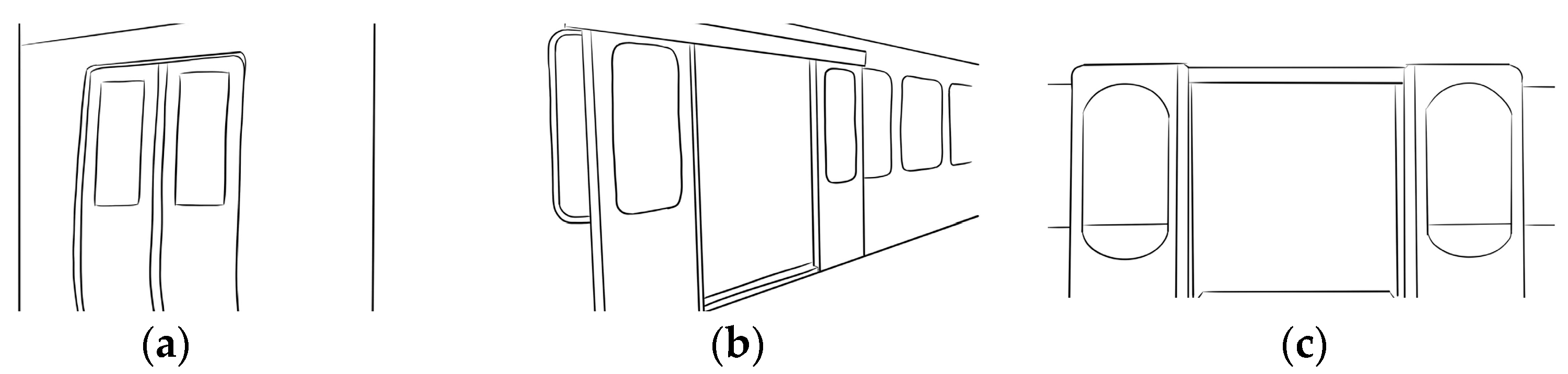
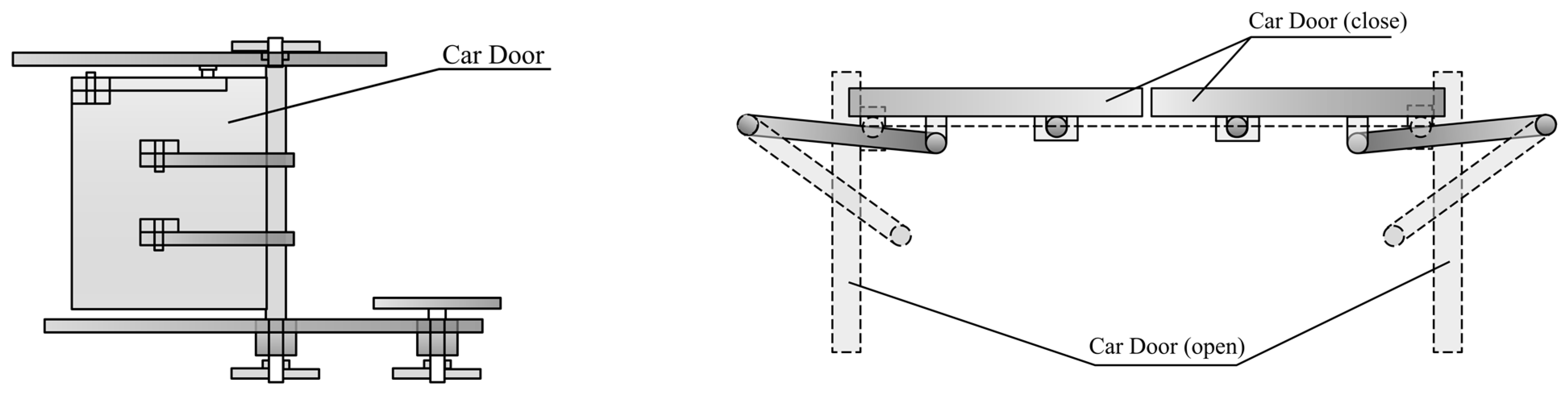
2.1.1. Subway

The doors for subways can be divided into three types: built-in side sliding doors, external doors, and sliding doors (Figure 1), the advantages and disadvantages of which are shown in Table 1.
As shown in Table 1, most of the doors are electric, and different types of doors are already used in the subway. In built-in side sliding doors, the main load-bearing structure is traditional plastic rollers. Xu’s research [12] suggests that using steel bearing systems is more reliable and durable with lower life cycle costs (LCC).
External doors are installed on the subway to solve the problem of the entire door occupying indoor space. Chen et al. [13] proposed a new transformation plan to add 12 mm of inner plug stroke to the external door to ensure the sealing performance of the sealing strip when the door is closed.
Zhang et al. [14] proposed that the sliding door utilizes a planar four-bar structure to connect different mechanisms, integrating and balancing the opening process.

2.1.2. Passenger Car
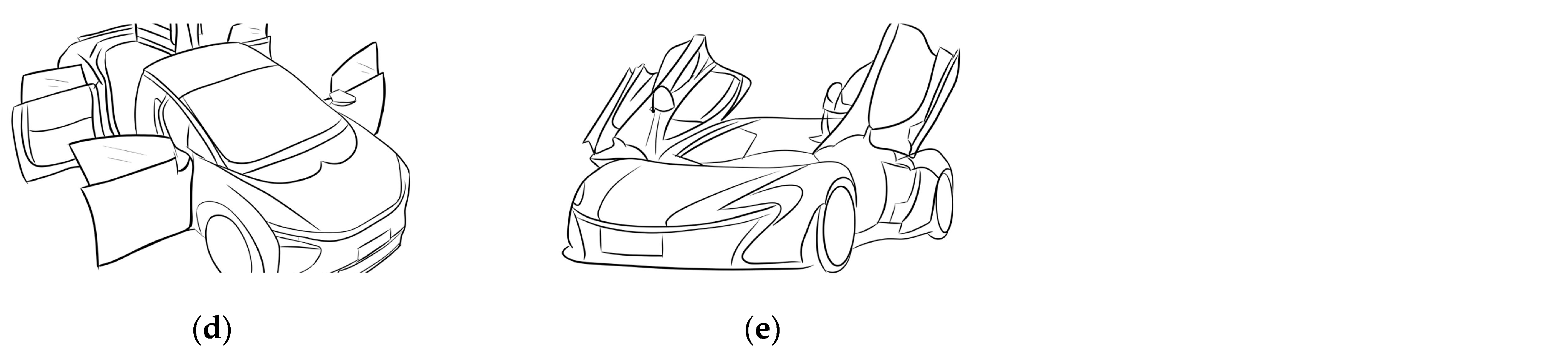
Passenger car (bus) doors have similar requirements to the subway doors mentioned above. There are many different types of doors in use, including folding doors, swing-out parallel moving passenger doors, and pendulum-type (electric) doors (Figure 2). The advantages and disadvantages are as shown in Table 2 below.
Li et al. [15] proposed that the opening and closing process of the folding door is achieved through the pulling and pushing forces generated by the door pump, so only a differential door pump is needed. This door pump can be installed in the lower part of the door, occupying minimal space and making it easy to arrange.
Some buses have been equipped with swinging-out parallel moving passenger doors. Jing et al. [7] proposed that the door is a kind of trackless swinging door with a planar four-bar structure. The main shaft and the driving arm are driven by a pulley to open and close the door.
Jing et al. [7] explained that the pendulum-type (electric) door uses a crank slider mechanism to convert the reciprocating motion of the slider into a rotational motion.
Bian et al. [16] proposed that the above three kinds of doors have different design problems, so a new type of door is proposed based on the characteristics of the above doors. In this design scheme, a sliding frame synchronous pendulum rod is used to ensure that both ends of the sliding frame slide out synchronously to prevent its tilt from being stuck. The door in the process of opening makes no interference with the passengers, which makes it easy for them to get on and off the car. At the same time, the curve of the door and the vehicle can uniformly reduce the wind resistance and have the advantages of good sealing, small impact during opening and closing movements, and low noise.

2.1.3. Car

Nowadays, most car doors are opened by rotation, which can be divided into straight doors, reverse doors, and upper doors according to the direction of rotation (Figure 3). Their peculiarity and common type are as shown in Table 3 below.
Conventional car doors with only one non-actuating degree of freedom (DOF) are dominant in the market. However, these doors can cause considerable discomfort to users in certain situations, such as when parking in a small lot or on a steep incline. Since the door detent typically provides a constant rest position, the user may have to manually secure the door during egress to prevent damage to the door and adjacent car. For medium inclines, this specific problem has recently been overcome by employing a (purely mechanical) variable door detent. Strolz et al. [17] considered that these doors can be quite uncomfortable for users in some cases. So, they proposed a new design that uses an actuator instead of a mechanical door detent, which can increase the comfort and safety of the door when operating. Going a step further, they proposed the use of actuated car doors with more than one DOF, thus providing superior comfort upon ingress.
Similar but not identical, Javier et al. [18] used a similar institution to solve another issue, using three pyrotechnic actuators, located on different parts of the door, to achieve controlled displacement of the door. The concept has two goals: to increase the internal clearance between the occupants and the doors, providing additional outward space for side airbag deployment, and to use the actuators themselves as energy-absorbing elements, effectively helping to reduce intrusion speeds. To ensure proper function, the system must be associated with stroke limiters and door guiding devices to ensure that the doors return to their original position during a collision.
Spencer [19] presented an invention involving a universal vehicle door replacement kit assembly, including a hinge mechanism that allows the vehicle door to operate in a swing-wing manner with an adjustable outward and upward movement. A structurally formed door plate/mounting bracket and a base plate/mounting bracket enable simple adjustment to attach the kit to a variety of automobiles without the need for templates or optional bolted or welded connection mechanisms. Multiple adjustable piston positions allow accommodation of a wide range of door masses.

2.1.4. Ergonomics of Land Civil Tools

The ergonomic design related to cars mainly focuses on the interior design of the car, such as dashboards, seats (e.g., Mohamed et al. [20]), etc., while the ergonomic design related to car doors, after a literature review, mainly focuses on the design of handles. The following will focus on the car handlebars.
Shamsuddin et al. [21] conducted focused research on the comfort of car door handles and focused the ergonomic evaluation on four key processing dimensions: height of handle from the ground, handle height, handle width, and location of the handle; they also used ergonomics software to explore the relationship between door handle size and comfort factors.
Relevant research has also been carried out on subway door handles. For example, Zhang et al. [22] mainly focused on ergonomic simulation analysis of subway car handrails, which will not be detailed here.

2.2. Civil Ship

2.2.1. Hatch Door Opening Method and Related Mechanism

The hatch structure, normally regarded as one of the most important parts of the ship, is widely used in shipboard equipment, such as the opening and closing of the ship channel and the opening and closing of the launcher hatch cover, which mainly serve to seal the hatch door and protect cargo and equipment in the cabin. In the early days, the traditional power mechanism of hatch covers was mainly manpower, while with the development of technology, modern hatch covers mainly use mechanical forms, which can be divided into tumbling type, folding type, side-shifting type, hoisting type, and roller type according to the hatch opening method (Figure 4) [1]. The following Table 4 summarizes the advantages and disadvantages of various door types.
As above, the hatch doors can also be divided into chain type, hinge type, rack type, and pull rod type according to the driving method when opening. As for the control of the opening and closing status of the hatch, most hatches adopt the structure of a motor (it rotates to open and close the hatch; it locks itself to realize the lock of the hatch) or a mechanical stop (manually open the hatch and limit the hatch angle through mechanical stops; manually unlock the hatch when closing). An innovative self-locking structure was designed by Liu [23] for the above situation, who mainly used the self-locking principle of the ratchet and pawl structure to realize the multi-angle opening and locking functions of the hatch and used compression springs and torsion springs to realize the reset function of the pressure rod and lock hook, satisfying the working strength and stiffness requirements. For ships equipped with a diving bell (such as the submarine rescue boat), the hatch cover adopts a moon pool hatch cover structure, which is directly connected to the sea water, forming a hull channel for the diving bell to be hoisted into the sea. In order to adapt this scene, Bei [24] designed the hatch cover of the moon pool using a hydraulic hinged double-page type, in which the cover plate is driven by a linkage mechanism and the hydraulic locking device is driven by a mechanical self-locking cylinder.

2.2.2. Classification by Ship Use and Related Mechanisms

Civilian ships can be mainly divided into the following five categories [1] based on their purposes: transport ships (cargo ships, passenger ships), engineering ships, fishing ships, agricultural ships, sports ships, etc. Current research on hatch mechanisms mainly focuses on cargo ships with specific uses, especially container ships and refrigerated ships; some other studies may focus on specific mechanisms. The following sections will provide a key introduction to the above content.
In light of the refrigerated ship, focusing on the design of the structural type, main dimensions, and component dimensions, Zhou et al. [25] designed the folding hatch cover of the middle deck and completed the motion stress analysis and typical layout analysis (for the end hinge device, roller device, and insulation device). Xie et al. [26] introduced the single-pull hatch cover into the structure of the refrigerated ship and provided an overview of its basic features, which, in addition to being a component for opening and closing the hatch, also play a role in the refrigeration, insulation, and thermal insulation of the cargo hold.
Considering the container ship, both Zhu [27] and Zhao et al. [28] carried out analysis on the calculation of the hatch cover structural strength; the former modeled and calculated the stress of the hatch cover and simulated it through finite element analysis software; the latter not only used the finite element direct calculation but also used standard calculations and proposed enhancement plans.
Under specific structures of hatch covers, Zhang [29] proposed two measures to solve the problem of difficulty in opening and closing the chain-type hatch covers of aging cargo ships (hydraulic combined with chain-type hatch covers is a common design method for cargo ship hatch covers), namely improving the chain adjustment method and welding repairs to repair worn tracks. Tang et al. [30] proposed the considerations for converting the lift-off hatch cover into a folding hatch cover, which mainly include the design of the end hinge-related mechanism, the design of the locking device, the design of surrounding accessories, movement trajectories and longitudinal limits, etc. Yu et al. [31] analyzed the layout of the rollers (which mainly play a supporting and guiding role) in the folding hatch cover and pointed out that if the hatch coaming space is sufficient, double guide rails can be used; otherwise, a single guide rail should be used. Wang et al. [32] proposed a technical design for a new type of hatch cover device that uses the superposition principle to design the hatch cover; meanwhile, he designed the power system of the superposition installation device and used the hydraulic control system to realize fully automatic operation of the hatch cover device.

2.2.3. Ergonomics of Marine Civil Tools

As the entrance and exit of the ship, the hatch is directly related to the loading and unloading of cargo, the safety and operating efficiency of the ship, etc., for which the ergonomics of the ship hatch are very important.
Guideline “The Application of Ergonomics to Marine Systems” [33] issued by ABS mentions the relevant design of hatch ergonomics, which mainly includes the design of hatch shape and size, the design of ladder frame and coaming, and the design of horizontal hatch size, etc. In view of horizontal hatch access through a deck, for access to the deck from a ladder below, the top of the ladder should be placed within 50 mm of the leading edge of the hatch opening. The minimum dimensions of the opening (round or square) are 810 mm, which is shown in Table 5 below.

2.3. Civil Aviation

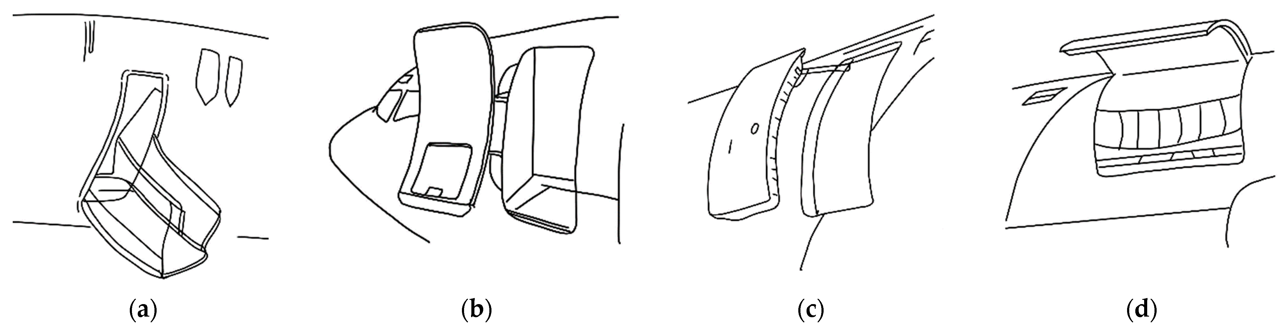
2.3.1. Cabin Hatch Form and Main Mechanism

The cabin hatch, as one of the key components in the aircraft’s structural design, is a complex component that integrates structure, mechanism, indication, alarm, and other systems and is mainly used for the entry and exit of personnel and cargo. According to the opening and closing capabilities of the cabin hatch under different operating and environmental conditions, it can be divided into three types: blocked hatches, semi-blocked hatches, and non-blocked hatches, among which semi-blocked sliding hatches have been widely used in the hatch design of various types of aircraft and have become the mainstream hatch design solution. Table 6 summarizes the characteristics of the three hatch types above. Figure 5 summarizes the classification of aircraft cabin doors according to the opening and closing methods.
Common blocked hatch mechanisms mainly include hatch frames, longitudinal beams, transverse partitions, spindle handles, observation devices, hinge arms, lifting mechanisms, latch mechanisms, slide release mechanisms, gravity balance mechanisms, parallelogram mechanisms, skins, etc. For the above-mentioned institutions, based on the airworthiness rules of civil aviation aircraft and the characteristics of composite materials, Chen [34] analyzed the working principles of key components of aircraft hatches, completed the overall structural design, and introduced in detail the key components, plies, and design methods of the connection between the door and the fuselage, which can provide certain references for the design of civil aviation aircraft hatches.
The above-mentioned stop block is the main structural component of the blocked hatch and semi-blocked hatch, by which the pressurized load can be transferred to the fuselage when the cabin is pressurized, with a lot of designs and research related at present. The research from Zhang et al. [35] introduced the design of the stop block’s layout and configuration on a certain type of semi-blocked hatch, conducted a tolerance analysis on the stop block contact area, and derived the calculation formula for the relevant tolerances.
As the currently widely adopted mainstream configuration for civil aviation aircraft, there has been innovative research and designs for semi-blocked hatch mechanisms, which mainly focus on virtual hinge opening mechanisms and intermittent motion mechanisms. Due to the constraints of the fuselage structure, aerodynamic requirements, door mechanism layout, and other factors, the rotation axis cannot be directly arranged on the outside of the fuselage, while the virtual hinge mechanism can realize the cabin hatch structure to rotate around the virtual hinge position on the outside of the fuselage during the hatch opening process, for the reason that this mechanism is widely adopted in mainstream semi-blocked flip-type cabin hatches, such as the cargo hatches of Boeing 777, front/rear cargo hatches of Boeing 757, emergency exits and cargo doors in the C series, etc. Based on the problem that the above-mentioned virtual hinge mechanism can only realize the flipping motion of the hatch and cannot follow it during the lifting process of the hatch, Ma et al. [36] added a set of high-pair connecting guide mechanisms through the cooperation of the lifting line and the lifting position lock mechanism, finally achieving lifting and flipping movements of the hatch door.
At present, most semi-blocked hatches have a series of sequential actions such as unlocking, unlatching, opening vents, lifting, and opening during the opening process, based on which Zhang [37] analyzed the use of intermittent motion mechanisms such as cam mechanisms, ratchet mechanisms, sheave mechanisms, planar link mechanisms, incomplete gear mechanisms, etc., which can have corresponding applications in the design of the hatch mechanisms.
In the design of civil aircraft cabin hatches, Ma [38] proposed the principle of adopting the combination mechanism method during overall design, especially adopting tandem mechanical structure (the tandem mechanical combination means that the output component of the previous sub-mechanism is the input component of the subsequent sub-mechanism), according to which he used a tandem combination of a four-bar mechanism and a cam mechanism, completing the design of the hatch mechanism by transmitting it through a hinge pair.
Since the hatches of large passenger aircraft generally hold a mass of more than 110 kg, their central position may shift during the opening process, causing posture deviation. Traditional aircraft hatches typically use toothed plates for posture adjustment, which makes it difficult to adjust the hatch position in all directions. Additionally, the opening branch of the existing lift arm 4R mechanism, connected in series with the hinge arm mechanism, cannot achieve all-directional adjustment of the hatch’s posture. To address these issues, Peng et al. [39] introduced a space mechanism to the optimized design and proposed a new aircraft hatch opening with a face-symmetric Bricard mechanism instead of the 4R mechanism. They analyzed its motion pattern and demonstrated its effectiveness in achieving the desired posture adjustments.
In summary, since their emergence, semi-blocked sliding hatches have been widely used in the hatch design of various types of aircraft and have become the mainstream hatch design scheme, based on which Ma [40] introduced two typical lifting mechanisms for semi-blocked sliding hatches in the article, analyzed the primary issues associated with these mechanisms, and proposed corresponding solutions such as using latch lifting mechanisms or hinge arm lifting mechanisms, etc.

2.3.2. Cabin Hatch: Various Functional Module Mechanisms

In the design of civil aviation aircraft door mechanisms, corresponding to the aerospace hatch mechanism, the locking mechanism, sealing mechanism, drive mechanism, and motion control mechanism of the aircraft are crucial. The following sections will focus on introducing these mechanisms, using the classic mechanism of the Airbus A320 as an example (Figure 6).
1.
Locking mechanism
The aircraft door locking mechanism is a complex model that integrates mechanical and hydraulic systems. Currently, relevant research mainly focuses on the following two aspects: the design and optimization of the mechanical structure and the modeling and simulation of the aircraft door locking mechanism.
Regarding the design and optimization of the mechanical structure, Guo et al. [42] proposed a locking mechanism that is suitable for the case where the cam linkage mechanism is used as the lifting mechanism and the hatch door is flipped outward and introduced its working principle and mechanism schematic diagram in detail in the article. focusing on the latch mechanism in the hatch door locking mechanism, Wang [43] introduced the three sub-mechanisms of the latch mechanism: the hook mechanism, the safety pin mechanism, and the lock hook mechanism axis, and proposed the design considerations to ensure compliance with airworthiness requirements. In order to ensure that the emergency hatch door locking mechanism will not be stuck due to structural deformation when the aircraft body is impacted, Jiang [44] designed a new locking method for the emergency hatch door based on the stress analysis of the aircraft body, which proves to have better impact resistance. Based on the perspective of ergonomics, in order to meet the requirements of airworthiness regulations and improve the operability of the hatch, Ma [45] combined the institutional characteristics of two different types of existing pressurized hatches and proposed two different forms of pressure locking mechanisms, “prevention door integrated into the pressurization” and “lock handle”, which respectively meet the requirements of the opening handle force of the pressurized door of civil aircraft in normal situations and under unsafe pressure.
In addition to the structural design and optimization of the locking mechanism mentioned above, some other research focuses on the modeling and simulation of aircraft door locking mechanisms. Early research on the motion of locking mechanisms mostly used experimental tests, which proves to be unrealistic to obtain a large amount of experimental fault data through experiments and conduct motion analysis on them. For this reason, modeling and simulation technology are mostly used at this stage. In order to study the movement rules of the locking mechanism, Zhu et al. [46] built a complete virtual experiment platform and used AMESim (Siemens PLM Software, version not specified) and LMS Virtual.Lab (Siemens Digital Industries Software, version not specified) simulation software to model and simulate the locking mechanism, which can effectively simulate the working state and obtain the internal parameters of the system. Due to the development trend of large-scale passenger aircraft doors, the gust lock (can prevent the aircraft door from shaking because of the gusts or other external forces) is required to withstand a sharp increase in the ultimate wind load. In response to this, Peng et al. [47] constructed a new gust lock mechanism composed of a swinging cam, a stop swing rod mechanism, etc., and used ASAMS and ANSYS to complete motion simulation and force simulation, respectively, meeting the corresponding working conditions. Jiang et al. [48] used different models to conduct modeling analysis on the failure mechanism and degradation analysis of a certain type of aircraft cabin door locking mechanism, which helps to improve the reliability and service life of a certain type of aircraft’s locking mechanism.
2.
Sealing mechanism
During aircraft flight, loads are distributed on the fuselage and cut structures due to the pressure difference between the cabin and the outside atmosphere. Gaps exist around the contours of the aircraft doors to accommodate the kinematics of the opening and closing mechanisms. To address this, current aircraft hatch doors mostly use elastic sealing. Based on this, Franke et al. [49] used the finite element method and ABAQUS/CAE 2018 (Dassault Systèmes) software to analyze different sealing methods and found the optimal solution for elastomer seals.
3.
Drive mechanism or motion control mechanism
At present, the research on the hatch drive system mainly focuses on two aspects: the research on the hatch drive method and related dynamics simulation, and the grasp of the precise motion trajectory during drive. In terms of driving methods, mainstream hatch drive systems are mainly traditional mechanical or mechatronic door drive systems. In view of the load requirements of the civil aircraft electromechanical drive system for the door opening mechanism, Zheng et al. [50] summarized the door opening mechanism into a flour-bar mechanism, established the kinematics and dynamics model of the door opening mechanism, and analyzed the motion mechanism and working characteristics of the opening mechanism through simulation. In the future, fully automatic door drive systems will gradually replace the traditional mechanical drive or semi-automatic door drive systems mentioned above. Based on this, Zhi et al. [51] designed a fully automatic passenger door drive system, among which the movement of the door latch and lock mechanism and the opening mechanism are completely controlled by multiple electric actuators; at the same time, the simulation results show that the system can meet the time requirements for emergency starting of the passenger door (airworthiness regulations stipulate that the cabin door should not be opened for more than 10 s in an emergency situation).
The accuracy of door motion control is an important aspect in evaluating the motion control mechanism, based on which, for example, in the Chinese commercial aircraft Comac ARJ21, one of the important goals is to make the target point of the door accurately move along the prescribed trajectory. Considering the impact of parameter disturbances (such as small changes in the size of mechanism parts, changes in parts or assembly tolerance, etc.) on the parameter optimization problem of the passenger aircraft door motion mechanism, Du et al. [52] improved the movement of the hatch through two different optimization models.
4.
New design
New design refers to using research or ideas from other fields to complete the relevant design or optimization of the hatch opening and closing mechanism, based on which two examples are listed below. Wang et al. [53] introduced the non-return mechanism (the core components of which are a ball-and-socket contact pair that provides compressive force and a multi-disc friction pair that provides braking torque) into the electric actuator structure for opening and closing the doors of amphibious aircraft to act as a brake and constructed the dynamic model of the check mechanism based on MATLAB/Simulink. Zhang et al. [54] used topology theory and metamorphic mechanism to analyze in detail the changes in the degree of freedom of the deformation mechanism during the door operating process before and after the operation and proposed an equivalent transformation method to analyze the configuration and configuration transformation of the hatch door through the equivalent transformation of variable-degree-of-freedom kinematic pairs.

2.3.3. Main Uses of Hatch and Related Mechanisms

According to the classification of uses, common aircraft doors can be divided into boarding doors, cargo doors, emergency doors, landing gear doors, etc. The following will focus on these four parts.
1.
Boarding doors
As a key component of civil aircraft doors, the boarding door has been studied in a large amount of literature, which mainly focuses on the principles and methods of the boarding door design process, the current mainstream mechanism design and optimization, etc.
In view of the design process and design principles, Zhang et al. [55] gave a comprehensive explanation of the typical boarding door hinge arm structure design, such as load sources, severe working condition screening, thickness and size optimization, strength verification, etc. By analyzing the boarding gate lifting mechanism of advanced aircraft models, Wang [56] summarized the design principles and design methods of the boarding gate lifting mechanism and specifically analyzed its design process and considerations. Yuan [57] mainly introduced the load analysis method, dynamic analysis basis, and mechanism strength analysis method of the aircraft boarding door mechanism.
At present, the boarding doors of small aircraft at home and abroad mostly adopt a door-ladder structure layout, which is convenient and easy to use but also has problems such as low operating efficiency and low safety. Wang et al. [58] optimized the design of the door-ladder-in-one boarding door mechanism from the perspective of ergonomics by using the software HyperStudy (Altair Engineering, version not specified) to optimize the intersection points of the mechanism, which resulted in the opening force of the outer handle being reduced by 31.4% after optimization. Zhi et al. [59] analyzed the cause of the problem of damage to the boarding door and shaft caused by the undamped free fall of the MA600 aircraft boarding door (the boarding door of the MA600 turboprop regional passenger aircraft is the first in China to use the door-ladder integrated structural layout, of which the power source for opening and closing the door mainly comes from a pair of hydraulic actuators with their own oil sources) and designed a new opening speed limiter that limits the boarding door’s falling speed.
At the same time, some optimized designs and analyses for special boarding gates are also being carried out. Ye [60] designed a side-opening boarding door, which includes a lifting linkage mechanism, a handle linkage mechanism, a lock mechanism, a slide pre-positioning linkage mechanism, etc. The patent Maraghe et al. [61] designed optimizes door hinges for passenger doors with a hinge mechanism that has an elongated gooseneck hinge member attached to the aircraft fuselage, reducing manufacturing and maintenance costs.
2.
Cargo doors
The main function of the cargo door of civil aircraft is to provide a passage for loading and unloading cargo, of which the relevant literature reviews mainly focus on two aspects: mechanism design and function realization.
Based on mechanism design, Zheng et al. [62] designed a set of adapting mechanisms for the opening and closing requirements of a certain type of civil aircraft cargo doors and completed the analysis by using dynamics simulation analysis software. Luo et al. [63] conducted multi-body dynamics modeling analysis on the cargo door mechanism and optimized the mechanism intersection points and gas spring parameters.
Considering the cargo door drive mechanism, Ma et al. [64] introduced a design method for a typical cargo door opening drive mechanism of a civil aircraft based on engineering software sketches, including the creation of mechanism principle sketches, rapid load analysis and calculation of four-bar mechanisms and virtual hinge mechanisms, stress result analysis, etc. Zhang et al. [65] used the CATIA sketch analysis module to conduct load analysis on different types of power sources for the hatch door based on factors such as the opening method of the door and the size of the load and performed a motion simulation analysis on the opening of the hatch door, verifying that its opening mechanism meets the functional requirements. In light of the airworthiness requirements of the civil aircraft cargo door drive system throughout its life cycle, Wang et al. [66] proposed a safety design method for the civil aircraft cargo door drive system based on the failure mode prediction results.
In addition, at the level of cargo hold door failure, Yu [67] designed a test method to verify the structural effectiveness of the door sealing performance; Sun et al. [68] conducted a mechanism analysis on the cargo hold door lock failure and proposed corresponding improvement measures.
3.
Emergency doors
Due to the limitations of factors such as the structural size, space, opening method, opening time, structural stiffness around the door, etc., the relevant design of the emergency door above the wing is vital and critical. Liu [69] used CATIA V5 software to digitally design the opening mechanism, motion connection mechanism, and opening drive mechanism of the emergency door and completed the corresponding motion analysis, which proves that the motion of the above mechanisms meets the technical requirements under the simulation. Ukadgaonker et al. [70] considered the stress near the emergency doors and windows of the Airbus A300B aircraft and conducted simulation analysis through an idealized model.
4.
Landing gear doors
Yin et al. [71] studied the emergency telescopic failure problem of the nose landing gear door linkage, developed a corresponding model, and proposed an effective solution that reduces the unlocking force by 33.0%. Hong et al. [72] used a joint simulation method to conduct a fault analysis on the emergency landing process of the nose landing gear of a certain type of aircraft, derived the motion equations of the mechanical system and hydraulic system, and obtained the boundary conditions for the emergency landing failure of the landing gear.

2.3.4. Ergonomics of Aviation

Similar to land civil tools, civil aviation-related ergonomics design mainly focuses on specific aircraft types or specific cabin space designs (e.g., wide-body aircraft cabins by Xie [73], business jet cabins by Guo et al. [74]) and seat design (Zhang et al. [75]), with less hatch-related designs; at the same time, relevant standards (e.g., China [76], America [77], Europe [78]) mentioned that the ergonomic design related to hatches is also based on guiding principles and lacks specific reference value.
Some other studies focus on the ergonomics of aircraft door emergency evacuation exits for passengers. McLean et al. [79] took repeated measurements of factors that control the emergency evacuation of passengers through the transport airplane type-III overwing exit (Table 7), which includes research design with mean total group evacuation times, etc.

2.4. Summary of Civilian Systems

This chapter systematically analyzes the opening and closing mechanisms of land vehicle doors, marine ship hatches, and civil aircraft cabin doors, highlighting their structural features, operation modes, and advantages and disadvantages. For land vehicles, it examines various types of subway and passenger car doors, discussing design issues and optimization solutions. For marine vehicles, it explores different hatch mechanisms and driving methods for various types of ships. In the aviation sector, it details the various functional modules and mechanisms of aircraft doors. The current problems primarily revolve around the complexity, safety, reliability, and operational convenience of door structures. Future research should focus on enhancing durability, reducing weight, and improving safety through the use of advanced materials and smart technologies, while also simplifying operation and maintenance.

3. Research on Cabin Opening and Closing Mechanisms of the New Carrier System

3.1. Landing Military System

3.1.1. Military Armored Vehicle

As a lightweight wheeled armored fighting vehicle, a military armored car is designed to enable combatants and equipment to quickly get on and off, for which the cabin opening and closing mechanism should follow the principles of simplicity and lightness. The traditional armored vehicle door opening and closing structure only uses a hinge mechanism. With the technology rapidly developing, door assistance systems have increased, which include pneumatic, hydraulic, and electromechanical solutions. Pneumatic systems (Parker Hannifin’s pneumatic door assist system, DAS, product [80]) are generally less expensive than the above solutions, which also prove to be simple to integrate into the vehicle doors without electrical system training, maintenance, and repair required like electromechanical solutions. Electromechanical solutions (TriMark intuitive motion control system, product [81]) are generally regarded as modular one-piece designs that improve serviceability in the field and the ability to retrofit into existing applications. Thomson (Thomson linear motion, product [82]) put linear actuators into combat lock with quick release pins to eliminate binding of the door. What is widely used as the door mechanism is a hydraulic cylinder driving a flip-down structure, while others may use a chain-transferring type to open a car door. Wei et al. [83] innovatively optimized the double-cylinder arrangement, slide rail, and trolley design targeting the hydraulic cylinder drive form, which indicates that a single occupant needs to provide 20 N of force to open the door, and the closing time is about 4.7 s when driven by the cylinder according to mechanical calculation, which meets the relevant requirements.
The door limit method is another design point for the armored vehicle structure because it prevents the door from falling during bumpy driving and causing vehicle damage and personal injury. The traditional door limit method uses springs, which have poor stability and are difficult to control. Yang [84] innovatively designed an articulated connection and spring limiter for armored vehicles, which can limit both horizontal and vertical directions. The horizontal limit structure keeps the door in a stable state when it is opened, which facilitates the use of the door, while the vertical limit structure prevents the door from oscillating up and down and sagging deformation when the armored vehicle is driving, avoiding damage to the door lock and extending the service life of the vehicle. Ji [85] innovatively used a chute and sliding shaft to limit the door opening mechanism, allowing the operator to portably realize the limit, position, and release of the door panel assembly. Huang [86] designed a limit structure for the rear door of a wheeled armored vehicle, using a combination of hinges, rotating shafts, and chutes to keep the rear door open and closed reliably under extreme stress conditions.
Doors on armored vehicles, industrial vehicles, and aircraft are designed to quickly eject from their frames in an emergency, which weigh up to four hundred pounds on armored vehicles, making them difficult to open in certain hazardous situations. For this reason, the armored vehicle door release system is generally regarded as another important point to design. Marshall [87] innovatively designed a releasable hinge assembly with an actuator provided for disengaging the latch members to move the latch members from the locked position to an unlocked position, which allows the door of the vehicle to be released and completely removed under emergency conditions. Pavlov [88] innovatively combined handle operation with the slide lock to achieve the quick release of the armored vehicle door, which needs two-stage operation to detach the vehicle door from the actuator mechanism.

3.1.2. Military Battle Tank

Compared to battle tanks’ offensive capabilities, mobility, and tracks, less attention has been paid to the hatch mechanism design of tanks, also known as the “tank crew hatch”. In the past decades, most tank hatch structures have been based on latch mechanisms, which are easily deformed under impact, causing an escape failure for personnel. Nowadays, mainstream tank hatch opening and closing mechanisms use shafts as rotary or open and close wrench devices, which form a lock inside the cabin. Other hatch mechanism designs feature a sliding hatch, such as the Black Shadow battle tank [89], the hatch of which slides to the light. Krauss Maffei [90] innovatively combined an actuating device with a linear guide on opening and closing mechanisms to control the hatch, as a result of which the upper part is raised from the lower part when slid by the actuating device.

3.2. Marine Military System

3.2.1. Military Classification and Related Introduction

According to their purpose, military ships can be divided into five categories: frigates, destroyers, cruisers, nuclear submarines, and deep-water manned submersibles. The hatch mechanisms of the first three types of ships are not the focus of ship design; some literature-related aspects are lacking, for which they will not be introduced in detail. However, some possible research focuses on the design of explosion-proof hatches for this type of ship. For example, Chen et al. [91] proposed a new three-dimensional zero Poisson’s ratio structure that can be applied to the sealing and blocking requirements of explosion-proof hatch doors.
The following part will focus on the latter two types of military vessels (nuclear submarines and deep-water manned submersibles).

3.2.2. Submersible Watertight Hatches

The core function of a submersible watertight hatch is to ensure strong sealing performance and structural strength under the high-pressure environment, which is consistent with the design requirements of spacecraft hatches. The watertight hatch can be divided into single-sided and double-sided load bearings according to the load-bearing mode. The single-sided pressure hatch door structure (almost all of them use hinges, springs, rails, etc., as mechanical structures) is simple, on which the sealing effect can be achieved by using the tensioning screw installed on the seat.
The most typical structure of a bi-directional pressured hatch cover structure is a hatch with an axial support (which can rotate along its own axis) and a handwheel, which uses a snap ring to clamp the hatch, and the hatch flange with a wedge lock, gear transmission, multi-handle pressing mechanism, etc., as mechanical structures.
When the wedge lock rotates, there is friction between the sealing surfaces, which is difficult for an adult to open or close because of the hard heaviness of the opening and closing mechanisms. Hence, most designs install a balancing mechanism or spring, or even use pneumatic or hydraulic transmission. Hu et al. [92] conducted research and analysis on the sealing performance of manned submersibles based on the current large-depth manned submersibles using rubber soft seals and handwheel locking, which concludes that the torque under human driving is about 20 Nm. To enable personnel in the cabin to manually open and close the hatch without the help of external force, Yu et al. [93] added the torsion bar spring as a key component to the hatch opening and closing system (the mechanical structure includes connecting rods, rotating shafts, torsion bars, locking devices, etc.), assisting personnel and ensuring sealing at the same time, and finally experimentally verified that the human opening force is about 160 N. Based on the demand for unmanned cabins of large-depth manned submersibles, Xu et al. [94] designed an opening and closing hatch cover with automatic opening and closing and automatic locking functions (using a rotary shaft, crank, opening and closing cylinder, etc., as mechanical structure) and verified its sealing performance and structure strength, which meet the requirements at the same time.
In consideration of the requirement of opening and closing the hatch for underwater robots, Jin et al. [95] proposed to employ a winch mechanism for hatch opening and closing with the primary principle of using the main control winch to rotate forward and reverse to drive the wire rope to pull the crank on the hatch.

3.3. Military Aviation System

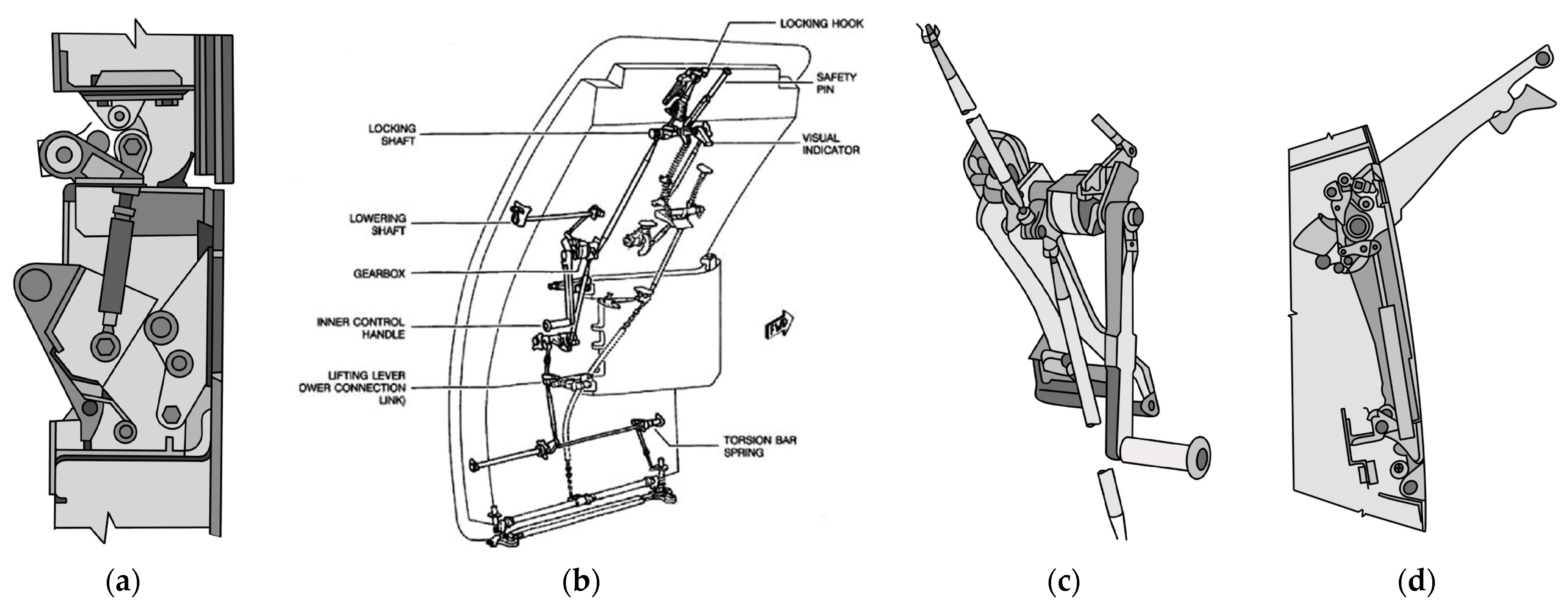
3.3.1. Helicopter Doors

Due to their fast speed, hovering, flexible response, and being not restricted by terrain conditions, helicopters have become an important unit in forming three-dimensional air-ground operations on the battlefield, for which they have become one of the most important components of the military aviation system. Helicopter doors nowadays serve the function of not only traditional works such as opening and closing but also new functions of extending as a platform to facilitate the entry and exit of personnel, door gunners, external storage compartments, etc., to adapt to the battlefield, of which typical forms include hinged doors and sliding doors. Among these, the latter is widely used in transport and general-purpose helicopters due to its large opening and small external space occupied after opening. The following Table 8 summarizes the features of the two types of mechanism doors mentioned above.
In order to provide a systematic method to design sliding doors, Xi [96] innovatively proposed a design method for the slide track of the embedded sliding hatch and completed virtual tests through relevant software (LMS Virtual.Lab, version not specified) to evaluate the sliding performance of the sliding hatch, which proved to significantly improve the design efficiency and precision of the sliding door’s motion system. Wu [97] analyzed the alarm failure of the existing helicopter door locking system, for which he found the reason why the installation structure of the microswitch of the locking mechanism was unreasonable and optimized the structure.
Xu [98] took the design of the helicopter door hydraulic retracting system as the starting point, using software (AMESim, version not specified) to model the system, and finally obtained a curve diagram of the door retracting time, which concludes that the optimal retracting time of the helicopter door is 8.9 s.
Wang et al. [99] designed the linkage retraction of the landing gear and the cabin door of the flying-wing aircraft, arranging a linkage mechanism between the landing gear and the cabin door based on the collision principle by analyzing and laying out the space, thereby realizing the linkage between the landing gear and cabin door in a small space.

3.3.2. Door Gunner

The helicopter door machine gun is a weapon system installed on the helicopter door and used for fire support and self-defense purposes to deal with air and ground threats. It is usually mounted on the doors or fuselage of the helicopter, allowing the crew and cabin personnel to use it while maintaining a level of protection [100].

3.4. Spacecraft

A spacecraft is a vehicle or machine designed to fly in outer space, which can be classified into three types: crewed spacecraft, space stations, and space shuttles [3]. Since the number of spacecraft launched into space by humans successfully is currently limited, the article will be divided into three parts according to the different uses of the spacecraft, respectively summarizing the characteristics of the hatch mechanism design on each model of spacecraft and the optimized design of related research.

3.4.1. Crewed Spacecraft

Crewed spacecraft hatches are generally composed of five modules [101]: the main load-bearing mechanism, the opening and closing mechanism, the compression and locking mechanism, the sealing mechanism, and the electronic auxiliary module, which mainly play the roles of protection, sealing, emergency evacuation, etc. The following Table 9 is a comprehensive comparison of various hatch mechanisms of crewed spacecraft at home and abroad, which are mainly based on body shape, main mechanical structure, mechanical layout, drive mode, turn-on direction, etc.
In addition to the hatch mechanisms listed above that have been in service for specific models, the following Table 10 is a summary of some more classic hatch mechanisms, including manual hatches with equal strength beams, manual hatches with spiral compression, and manual hatches with planetary gear loading [9].
For the design of hatches in crewed spacecraft, the hatch opening and closing mechanism, hatch jettison system (i.e., emergency escape system), and hatch locking mechanism are of utmost importance, to which many documents analyze and optimize the design.
Regarding the motion of the hatch opening and closing mechanism, Tian et al. [102] used the parameter optimization functionality of ADAMS software (MSC Software Corporation, version not specified) to optimize the design for the motion pattern and the structure of the opening and closing mechanism of a specific hatch, with an electric motor driven six-bar mechanism employed to ensure the pressure angle while enabling the actuator to rotate exactly to 165°. To address the vibration issue caused by root hinge clearance during the spacecraft hatch opening and closing process, Zhang et al. [103] proposed optimizing the material parameters of the model by using digital twin technology, which proves relatively good results that the dynamic performance of the hatch is improved. Zhang et al. [104] developed an operating mechanism that is a typical variable freedom mechanism for the spacecraft hatch with a basic variable freedom joint, analyzed its topological structure, and performed a kinematical simulation of each configuration based on the problem of the differences among mechanism components, which are blamed for the unsteady operation of the mechanism.
The crew hatch release system of a manned spacecraft allows astronauts to safely open and disengage the hatch after the spacecraft has landed, which is also designed to meet the requirements of emergency evacuation in case of urgent situations, for which there are specific requirements for the hatch’s opening time and the magnitude of force. Early crewed spacecraft projects used detonating explosives to release the hatch to ensure that astronauts could quickly exit the cabin, such as the Mercury Project, Vostok, and the overhead escape window of the space shuttle orbiter; some also used gas ignition drives or pressurization, such as the Gemini Plans, which use pyrotechnic drives; the Apollo Plans, which use firing pins, etc., under the zero-gravity simulated unloading test conditions of the spacecraft hatch, Zhao et al. [105] used a two-dimensional slide rail hanging method to develop the trajectory to solve the complex problem of the space hatch’s operating trajectory; used multi-point long-distance to solve problems such as large mass, easy deformation, and difficulty in unloading; and used flexible adaptive elastic elements to design the system for rigid collisions. (This scenario is mainly aimed at conventional hatch unloading conditions, such as returning to the ground, rather than emergency situations).
The hatch locking mechanism is another important design direction, as well as a key technology, of the spacecraft hatch, which mainly ensures the sealing of the hatch and the safety of the astronauts inside the cabin. The traditional hatch mechanism operation method is manual, by which the astronauts need to operate with their feet fixed; with the development of technology, the use of large diameter manual with electric hatch mechanisms is the trend in the design of spacecraft hatch mechanisms. LaValle et al. [106] proposed a technical solution for electric and manual hatches using multiple sets of electromagnetic clutches to engage and disconnect, which can and only achieve the electric start of hatches in the cabin. Since this solution is orderly, it now appears to have a complex structure and high power consumption. In view of the shortcomings of the existing hatch design’s high consumption, complex structure, and inability to be electrically activated both outside and inside the cabin mentioned above, Qian [107] designed a new hatch mechanism that can be operated electrically and manually both outside and inside the cabin, which uses a flip mechanism to achieve opening and closing functions and eight roller frames to achieve synchronous movement. This proved to have an improvement in sealing effectiveness, lower electric power consumption, increased portability for astronauts during operation, and reduced actuation force.
In fact, another major indicator of the hatch locking mechanism is the sealing test of the hatch, known as the hatch leak test. During the proof pressure test [108] on an engineering development unit of the Orion crew module side hatch assembly, the hatch prematurely separated from the proof test fixture at a pressure of 23.32 PSIG due to excessive structural deflection and the gearbox latch restraint not being engaged, among other reasons. This incident has since evolved into a significant joint failure investigation. Li et al. [109] conducted a comparative analysis of existing spacecraft hatch leakage testing methods, such as hatch quick leak detectors and vacuum chamber leak testing, in daily scenarios, which shows that the leakage rate obtained by HQLD is higher than that of VCLT, proving that HQLD is an effective method for daily leakage detection at space hatches.
In the design of the crew cabin door for crewed spacecraft, relevant theories of human-machine ergonomics are involved. Taking the Chinese crewed spacecraft Shenzhou series as an example, Shenzhou 1 was equipped with a 650 mm diameter return capsule door and a 750 mm diameter orbital module side door, which, in the Shenzhou 7 phase, was changed to an 850 mm diameter egress door and continued to be used in the “Three-phase Project” [10]. These three types of hatches use a central switch to apply force and a peripheral compression mechanism, which should consider the characteristics of human-machine functions when being designed [110] (The solutions in brackets refer to the Shenzhou series of spacecraft):
  • It can be opened and closed conveniently from inside and outside the cabin. (By using transmission mechanisms to achieve internal and external operations and sealing the cabin).
  • It requires little force and a short time when operating. (By using a higher gear transmission ratio to reduce the operating time).
  • It needs to withstand repeated opening and closing operations on the ground.
  • It needs to ensure the safety of astronauts when operating. (By being equipped with a handle and locking mechanism to prevent misuse).
(The above design guidelines are consistent with NASA Spaceflight Human-System Standard Volume 2 [110]).
In addition, a rapid hatch leak detector device is designed to enable ground staff and astronauts to confirm the sealing of the hatch within 10 min after closing the hatch, starting from Shenzhou 4 [10]. A pressure equalization valve is installed on the return capsule door, which astronauts can manually control to achieve pressure balance between the two cabins, much more easily opening the cabin door.

3.4.2. Space Station

Compared with the manned aircraft cabin hatch communicated between the cabin environment and the outside, which mainly plays the role of sealing, emergency escape, and protection, the hatch of the space station mainly takes an important part in connecting different functional modules and acts as a partition due to the presence of multiple modules in the space station. The following Table 11 is a comprehensive comparison of various hatch mechanisms for space stations at home and abroad [3]. (CM: Command Module; EVA: Spacewalk Extra-Vehicular Activity; DTM: the Docking and Transfer Module).
In the space station, the astronauts’ living cabin must be a sealed cabin to ensure their safety, for which the on-orbit sealing performance of the cabin door is particularly critical. At present, the space station hatches are larger in size, more numerous, and more complex in structure compared to the crewed spacecraft hatches. However, the sealing performance detection method for crewed spacecraft mentioned above is difficult to meet the diversified and batch requirements of the space station hatches. For example, Chen [10] mentioned in the article that the sealing chamber leakage rate requirement is reduced from 1 kg/d for crewed spacecraft to 0.1–0.2 kg/d for the space station. Therefore, the testing of sealing performance for space station module doors tends to be a more universal approach. Steve et al. [111] developed leak detection equipment suitable for the general hatch of the International Space Station (ISS), which is mainly used to test the leakage rate of the main shaft, observation window, and hatch seal of the hatch. Based on the need for leak detection of the hatch of the space station under research in China, Zhang et al. [112] proposed a new universal hatch leak detection equipment that achieves a wider range of test temperatures, an oil-free vacuum system design, bidirectional leak testing of the module door, and a shorter system response time (has been optimized to 2.5 s) compared to the above research. In addition to the leak detection mentioned above when the space station is in service, Zhang et al. [113] also proposed a set of technologies for leak detection before launch, which are mainly used for the door body and door frame seal, the entire hatch, hatch components, and hatch parts.
Considering the three aspects of ergonomic design, which include the human body, machine, and environment, the design parameters related to the environment in the space station are as follows (Table 12), taking the Mengtian experimental cabin [114] as an example.
Among them, the load transfer mechanism is mainly used for transferring cargo inside and outside the cabin [115], which has telescopic and rotating functions; the maximum telescopic distance is 1800 mm, and it can rotate 90°. The inner hatch adopts a square manual hatch with a diameter of 1250 mm × 1310 mm; the outer hatch adopts a curved automatic hatch with a diameter of 1230 mm × 1250 mm.

3.4.3. Space Shuttle

Consistent with the hatch functions listed above, the space shuttle’s hatch plays a key role in maintaining the safety of astronauts, ensuring the success of the space shuttle mission, and maintaining the stability of the space shuttle’s internal environment. The following Table 13 is a comprehensive comparison of various hatch mechanisms for space shuttles at home and abroad.

3.5. Other Extreme Environmental Systems

The characteristics of extreme environments in aerospace conditions, such as ultra-low temperature, intense radiation, high vacuum, high speed, etc., can also be found in certain specific places on the earth. Consequently, corresponding design requirements exist for the manned system hatch mechanisms that are tailored to match these environmental conditions. In addition to the deep-sea environment, space environment, etc., described in detail above, other extreme environments such as polar environments, deep crustal environments, and submarine experimental stations have not been mentioned. After investigation, there is also a lack of corresponding hatch mechanism design research for this environment. Now focusing primarily on deep crustal environments without expanding on other aspects.
For the deep crustal environment, relevant research mainly focuses on patents. Both Ye et al. [116] and Wang et al. [117] carried out relevant optimization for the retraction mechanism of the shield machine cabin door used in the earth’s crust: the former designed an automatic disassembly and assembly device for the safety pin of the shield machine mud door; the latter designed a quick locking device for the bulkhead door.

3.6. Summary of Military and Space Systems

This chapter presents a comprehensive analysis of the opening and closing mechanisms for land-based military system hatches, marine military system hatches, and space vehicle hatches, including those on spacecraft, space stations, and space shuttles. It outlines the current designs and highlights the challenges faced in each domain. For land-based systems, issues include the complexity of hinge mechanisms and the need for quick egress in emergencies. Marine systems require robust, watertight hatches capable of withstanding high pressure, while space systems demand reliable seals and efficient emergency egress mechanisms. The future direction involves integrating advanced materials and automation technologies to enhance durability, reduce manual effort, and improve safety across all systems.

4. Guidance for the Engineering Design of Aerospace Door Mechanisms

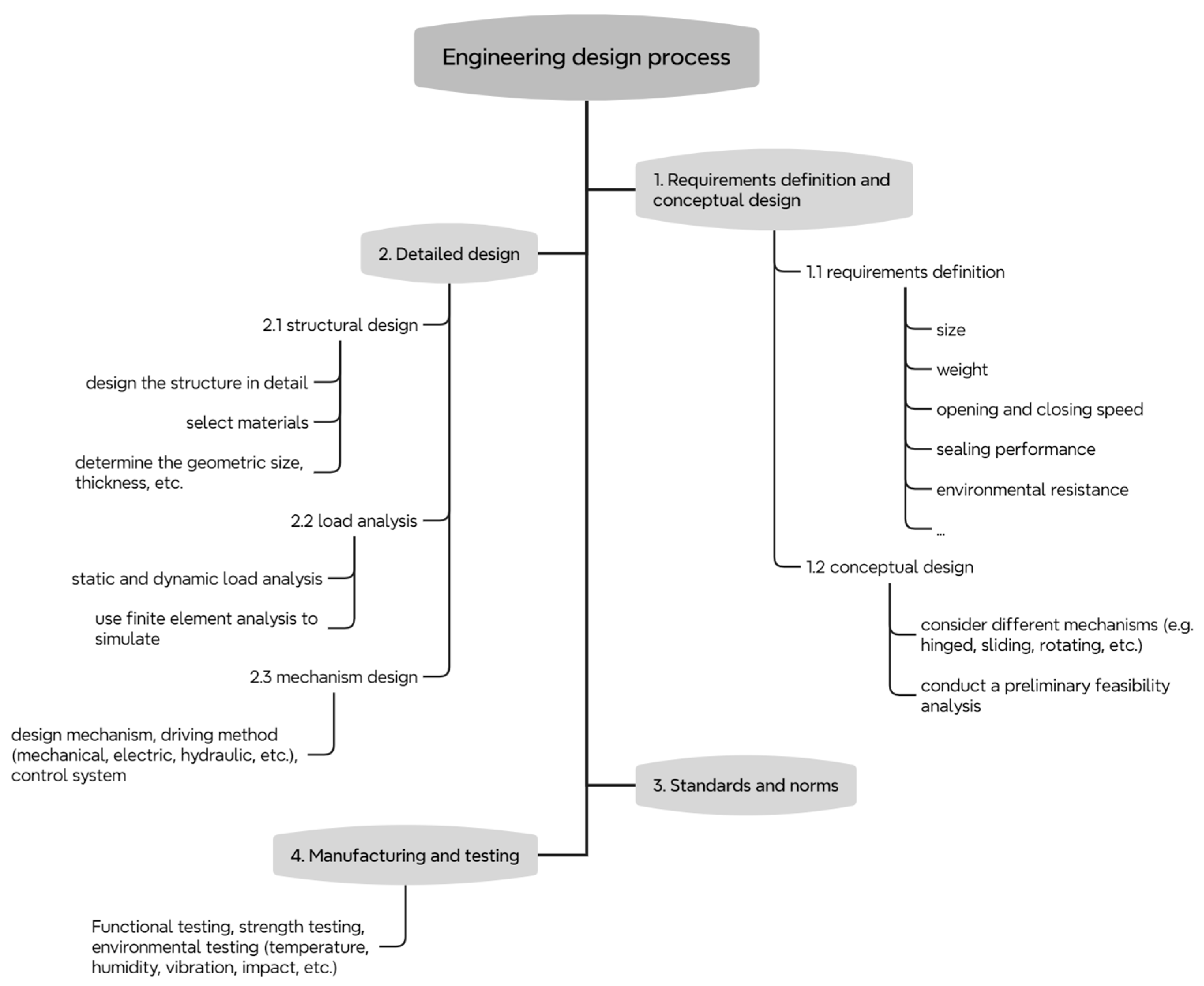
4.1. Engineering Design Process in the Technical Department

Although there is currently no specialized literature that comprehensively details the engineering design process for aviation or space capsule door mechanisms, a summary of the typical engineering design process conducted by technical departments can be derived from previous studies that focus on different aspects of the design stages. It is noteworthy that the design processes in the aviation and space sectors exhibit a degree of universality; thus, they are combined into a single flowchart. The engineering design process primarily includes four major stages: requirements definition and conceptual design, detailed design, standards and norms, and manufacturing and testing (Figure 7).
At the outset of the design process, engineers conduct conceptual design to determine the basic functions and shape of the door. This stage involves preliminary engineering calculations and simulations to ensure that the design meets fundamental requirements. Once the conceptual design is established, the process moves into the preliminary design process, where most subsystems begin to take shape, including structural design, material selection, and load analysis. Multiple iterations are typically required to achieve the final design. Upon completion of the preliminary design, the detailed design process further refines all subsystem details, ensuring seamless integration of all components. This stage involves more in-depth calculations and analyses, utilizing tools such as finite element analysis (FEA) to verify the reliability and functionality of the design.
Several articles [118] mention the adoption of a novel design methodology, concurrent engineering (CE), in the engineering design process to replace traditional sequential design methods in order to reduce costs. This approach involves conducting multiple design processes (e.g., stress analysis, aerodynamics, and material analysis) simultaneously to shorten the development cycle and reduce the number of changes required. Building on concurrent engineering, integrated product and process development (IPPD) is also employed, involving production, quality assurance, procurement, and marketing personnel within the team. This ensures that the product design considers the entire lifecycle requirements from the outset.
The definition and discussion of design standards will be discussed in Section 4.2. Research progress in improving the design process will be discussed in Section 4.3. Actual use testing or inspection will be discussed in Section 4.4.

4.2. Design Standard Definition and Discussion

Through extensive and in-depth research, no specific standards directly targeting the design of aerospace doors have been identified. However, relevant standards can be found within other related standards. For instance, design requirements for door opening and closing mechanisms can be found in the “Design and Development Requirements for Mechanisms” [119], and material requirements for doors can be found in the “Standard Materials and Processes Requirements for Spacecraft” [120]. Examples of some NASA standards are presented below, outlining their relevance to door design (Table 14).
In designing aerospace or spacecraft door mechanisms, strict adherence to design standards and technical specifications is crucial.
For static load selection, which refers to constant stress on the door in the closed state due to internal and external pressure differences and its own weight, finite element analysis (FEA) tools can be used to simulate stress and deformation of the door structure under maximum static load. NASA-STD-5002 [123], “Load Analyses of Spacecraft and Payloads”, which specifies safety factors and design requirements for static loads, can be referenced.
For dynamic load selection, which refers to transient stress during door opening and closing due to motion and aerodynamic effects, multibody dynamics (MBD) tools can be used to simulate the dynamic behavior of the door and analyze stress variations during operation. NASA-STD-5001 [121], “Structural Design and Test Factors of Safety for Spaceflight Hardware”, which specifies load testing environmental conditions and safety factors, can be referenced.
In terms of structural dimension design, the principle is to ensure that the door structure meets strength and stiffness requirements while minimizing weight. Topology optimization and parameter optimization techniques are often used to optimize the door’s geometry and material distribution. NASA-STD-5017 [119], “Design and Development Requirements for Mechanisms”, which outline component design requirements, or the previously mentioned ergonomic dimension requirements, can be referenced.
Function verification can be carried out through prototype testing (manufacturing a door prototype and conducting ground tests to verify its function and performance under simulated flight conditions), environmental adaptability testing (testing the door under various temperature, humidity, and pressure conditions to ensure it works normally in all environments), and other methods. This section will be elaborated upon subsequently.
For reliability, design redundancy (designing redundant structures at critical points, such as multiple locking devices, to improve system reliability), failure mode and effects analysis (FMEA, identifying potential failure modes, evaluating their impact, and formulating preventive measures and contingency plans), and reliability verification (using accelerated life testing and reliability modeling to verify the door mechanism’s reliability throughout its service life) can be considered. NASA-STD-5001 [121] provides detailed reliability design and verification requirements.
Additionally, SAE ARP 4754 [126] offers a comprehensive approach to systems engineering and verification, mainly for the development of civil aircraft and their subsystems, and MIL-STD-810 [127], the US Department of Defense’s standard for environmental engineering considerations and laboratory testing, provides standard procedures for testing under extreme environmental conditions. These can also serve as technical reference standards in the design process of aerospace doors.

4.3. Research Progress on Improving the Design Process

Recent advancements in the design process of aerospace doors primarily focus on improved materials and manufacturing techniques. Notably, the use of advanced composite materials, such as carbon fiber-reinforced polymers (CFRP), offers a superior strength-to-weight ratio. Integrating these materials into door design can significantly reduce the overall weight of the aircraft door while maintaining structural integrity and safety standards. Additionally, CFRPs enhance fatigue resistance [128].
Moreover, 3D printing technology is increasingly being used in the manufacturing of complex aerospace components, including door mechanisms. This technology allows for the production of parts with intricate geometries that are lighter and stronger than those made with traditional manufacturing techniques. It also reduces waste and lowers production costs.
There are also other emerging technologies that can be applied to aerospace design. For instance, digital twin technology can be used to create virtual models of door mechanisms, allowing engineers to simulate and analyze performance under various conditions. This technology enables real-time monitoring and predictive maintenance, thereby improving reliability and performance. Artificial intelligence (AI) and machine learning (ML) algorithms can optimize the design process. These technologies help predict potential failure points, optimize material usage, and enhance overall design efficiency. The integration of health monitoring systems using sensors and Internet of Things (IoT) devices allows for continuous monitoring of door mechanisms. These systems can detect anomalies and wear in real-time, enabling proactive maintenance and reducing the risk of in-service failures. However, there is currently limited research on applying these new technologies to optimize the design process. Therefore, these examples are provided to inspire potential innovations for designers.

4.4. Actual Use Test or Inspection

In the testing and inspection of aerospace door mechanisms, key issues primarily focus on the following aspects:
  • Reliability and durability issues. The mechanism needs to maintain high reliability and long-term durability in various extreme environments. Numerous studies have highlighted the wear and degradation of mechanical components under different environmental conditions. For instance, NASA-STD-8729.1 [129] introduces in detail the safety, reliability, maintainability, and quality assurance requirements in the aerospace design process.
  • Multi-failure mode analysis. In practical applications, mechanical mechanisms may experience multiple failure modes. Analyzing these modes and their impact on the overall reliability of the system is crucial. Research indicates that integrating databases and expert systems can effectively identify and address these failure modes, thereby enhancing overall system reliability [130].
  • Thermal vacuum testing. Thermal vacuum testing is a critical step to ensure aerospace mechanisms function correctly under extreme temperature and vacuum conditions. These tests include thermal cycling, thermal balance, and bake-out tests to ensure thermal stability and functional integrity in space environments.

5. Bionic Door Mechanism and Related Designs

With the development of technology, bionic design, as a new perspective, provides a new way of thinking for solving engineering problems. The combination of bionic design and car door or hatch structural design usually focuses on the impact resistance and anti-collision design of the door, but rarely on the design of the opening and closing mechanism; at the same time, bionic objects are mainly concentrated in the Plantae, and a small number in the Animalia. Through the review and investigation of bionic doors, new ideas or new prospects can be provided for the design of future hatch mechanisms to a certain extent, the following of which will be focused on the above aspects.

5.1. Bionic Design for Anti-Collision Door Structure and Stiffener

The combination of anti-collision doors and bionic design is the mainstream direction of door structure design or optimization under the guidance of bionic thinking, among which the optimization of reinforcing ribs and door filling core account for the main part. Xu et al. [131] carried out a multi-objective bionic optimization design for the door stiffeners based on the dragonfly wing pattern unit. By analyzing the distribution characteristics of the dragonfly veins and the similarity of the stiffeners, he extracted the excellent mechanical performance and structural characteristics of the dragonfly veins as a bionic design, based on which the finite element analysis shows increased deformation and vibration resistance of bionic stiffened doors. Xiao et al. [132] proposed a multi-scale bionic topology optimization method under cyclic variable loads, optimizing the dynamic flexibility of leaf vein formation and distribution and analyzing the sensitivity of thin-wall dynamic flexibility to rib thickness. The experiment verified that the maximum stress value of the car door inner panel with the bionic topology structure was reduced under anti-dent and sinking conditions.
Furthermore, a few patents focus on the optimization of car door anti-collision systems by bionic design, which focuses mainly on structural design. Lu et al. [133] invented an anti-collision door based on a cactus structure and its optimized design method. The door filling inner core is mainly based on the cactus appearance structure for bionic design support, through the pure fold deformation of which, when it is subjected to external impact, the vehicle is protected from impact. Wang et al. [134] invented a bionic clover negative Poisson’s ratio door anti-collision system and its hierarchical optimization method, taking advantage of the bionic clobber negative Poisson’s ratio structure’s advantages of light weight, strong energy absorption, and easy optimization.

5.2. Bionic Design to Hinge Connection Mechanism Design and Others

Yang et al. [135] proposed a new stick-slip piezoelectric-driven positioning platform by imitating the body structure and movement pattern of natural crabs using a symmetrical structure and a bionic flexible hinge mechanism with two stacked piezoelectric. Ling et al. [136] proposed a bionic design of a new concave-convex bending hinge with adjustable curvature, inspired by the biconcave disc morphology of red blood cells, while verifying the high precision and low stress of this new flexible hinge through comparative studies.
It is worth noting that a bionic design is provided for a one-way door to prevent escape space debris, which belongs to the field of aerospace technology and may provide relevant ideas for the optimization design of aerospace hatches. Jia et al. [137] proposed an anti-escape space debris storage one-way door based on a spider web bionic mechanism, which uses numerous combined units divided in circumferential and radial directions combined with a design of hydraulic hinges to effectively prevent new space debris from passing through the one-way door, reducing the risk of contained space debris escaping from gaps.

5.3. Integration of Claus Mattheck’s Principles

Claus Mattheck is a renowned researcher in the field of bionic design, particularly noted for his work on mechanical design principles derived from trees and bones. His research focuses on how natural structures can inspire innovative engineering solutions. Although his theories are not directly applicable to the design of aerospace door mechanisms, referencing his pioneering work can guide the incorporation of bionic methods in aerospace door mechanism design.
Mattheck’s book Trees: The Mechanical Design [138] explores how tree structures can inform the design of mechanical components. He introduces the concept of “self-optimization”, where trees naturally develop structures that efficiently handle loads and stresses. This principle has been applied in various engineering fields, including the design of automotive components by companies such as Opel and Mercedes. Another significant work by Mattheck, Design in Nature: Learning from Trees [139], delves deeper into these principles and has influenced the development of software tools for engineering design. These tools mimic the load distribution found in trees and bones, aiding engineers in creating components that are both lightweight and strong, thereby optimizing material use and structural integrity.
In summary, Mattheck’s research emphasizes the simulation of natural load distribution and stress management. Designers of aerospace door structures can benefit from his principles by applying similar load distribution designs to enhance structural efficiency and integrity.

5.4. Architecture and Mechanical/Structural Elements of the Bionic Door Mechanism

The architecture of a bionic door mechanism is a complex system integrating several key components inspired by biological principles. This innovative approach seeks to mimic the efficiency and resilience found in nature, offering enhanced functionality and durability. Summarizing the specific design details from previous researchers listed above, the primary components of this architecture include:
1. Bionic Stiffeners: These elements are modeled after natural structures such as dragonfly wings [131] or cactus spines [133]. The stiffeners are strategically placed within the door to optimize load distribution and enhance structural integrity without adding significant weight. This design philosophy follows Claus Mattheck’s principles of “self-optimization” [138], observed in natural structures like trees and bones.
2. Flexible Hinges: Inspired by the flexible joints found in crabs [135] or the curvature of red blood cells [136], these hinges allow for smooth and controlled door movement. They are engineered to handle dynamic loads while maintaining high precision and low stress, which is crucial for aerospace applications where reliability and accuracy are paramount.
3. Impact Absorption Systems: Utilizing principles from biological structures such as cactus spines [133] or spider webs [137], these systems are designed to absorb and dissipate energy efficiently during collisions. This capability is particularly important for aerospace applications, where impact resistance is a critical requirement.
The mechanical and structural elements in bionic door mechanisms are shown in Table 15.
By incorporating these elements, the bionic door mechanism leverages the principles of natural design to achieve superior performance and durability in aerospace applications.

5.5. Comparison of Standard Kinematic Mechanisms and Specifications for Qualification Tests

Bionic designs offer several advantages over standard kinematic mechanisms but also present unique challenges.
Advantages: (a). Enhanced structural integrity. Bionic designs distribute loads more efficiently, resulting in stronger and lighter structures. The biomimetic approach allows for optimized stress distribution, which enhances the overall durability and performance of the aerospace doors. (b). Improved impact resistance: Natural optimization in bionic designs leads to superior energy absorption and dissipation, making these mechanisms more resilient to impacts. This is particularly beneficial in aerospace applications where safety and reliability are paramount.
Challenges: (a). Complex integration: Incorporating complex bionic designs into existing engineering frameworks can be challenging due to differences in manufacturing processes and materials. Adapting these innovative designs to current production lines often requires significant adjustments and new technologies. (b). Material compatibility: Ensuring the materials used in bionic designs meet aerospace standards and can withstand harsh conditions is a significant challenge. The materials must endure extreme temperatures, radiation, and other environmental stresses without compromising performance.
To ensure that bionic door mechanisms meet stringent performance and safety standards in aerospace applications, they must undergo rigorous qualification tests. These tests include the following:
1. Load Testing: Verifies that the bionic door mechanisms can handle both static and dynamic loads without failure. This includes testing under maximum expected loads and repeated cycles to simulate long-term use.
2. Environmental Testing: Confirms that the materials and structures can withstand extreme temperatures, radiation, and other environmental conditions typical in aerospace settings. This testing ensures the doors maintain functionality and structural integrity in the harsh conditions of space.
3. Impact Testing: Evaluates the door’s ability to absorb and dissipate energy during collisions. This test is critical for ensuring that the door can protect both the spacecraft and its occupants from impacts and sudden forces.
By comparing these bionic designs to standard kinematic mechanisms, it becomes evident that while bionic designs offer significant improvements in structural integrity and impact resistance, they also require careful consideration of integration and material selection to meet aerospace standards. These advancements in design must be validated through comprehensive testing to ensure they can reliably perform in the demanding conditions of aerospace applications.

5.6. Summary of Bionic Door Mechanism Design

This chapter delves into the bionic design of door mechanisms, focusing on the application of biological principles to enhance structural integrity and functionality. It examines anti-collision door structures inspired by dragonfly wings and cactus structures, highlighting improvements in impact resistance and energy absorption. Innovations in hinge mechanisms, drawing from natural models like crab joints and red blood cells, are also explored for achieving high precision and low stress. These bionic principles are extended to aerospace technology, particularly in designing one-way doors for space debris containment.
The principles of Claus Mattheck have been integrated into this exploration. Mattheck’s research on mechanical design principles from natural structures, such as trees and bones, emphasizes “self-optimization”, where structures develop to handle loads and stresses efficiently. This concept can guide the incorporation of bionic methods in aerospace door mechanism design.
The architecture of a bionic door mechanism incorporates key components inspired by biological principles, including bionic stiffeners, flexible hinges, and impact absorption systems. These elements optimize load distribution, enhance structural integrity, and improve impact resistance. Comparing bionic designs to standard kinematic mechanisms reveals significant advantages in structural integrity and impact resistance, though challenges like complex integration and material compatibility must be addressed.
Future research should focus on refining these bionic designs and developing advanced materials and manufacturing processes to facilitate their integration into aerospace applications. Rigorous qualification tests, including load, environmental, and impact testing, are essential to ensure these designs meet the stringent performance and safety standards required for aerospace use. By addressing these challenges, bionic door mechanisms can achieve superior performance and durability, contributing to the advancement of aerospace technology.

6. Conclusions

This review systematically investigates existing door mechanisms in civilian and military systems, categorized by land, sea, deep sea, aerospace, and other extreme environments. It explores the required functionalities of doors in different systems and corresponding mechanism designs, such as sealing, driving, locking, and linkage mechanisms. Additionally, the review also conducts related research on ergonomic design in the above directions and proposes corresponding ergonomic considerations for each direction. Finally, the review surveys biomimetic door mechanisms and offers prospects for the future integration of door mechanisms and biomimetic designs in aerospace systems.

Author Contributions

Conceptualization, Z.C. (Zhiwu Cui), H.W., M.Z. and Z.L.; methodology, Z.C. (Zhiwu Cui), Z.C. (Zhihe Cui), H.W. and H.H.; validation, M.Z., Z.C. (Zhihe Cui) and H.W.; formal analysis, Z.C. (Zhiwu Cui) and H.W.; investigation, Z.C. (Zhiwu Cui) and H.W.; data curation, H.W.; writing—original draft preparation, H.W.; writing—review and editing, H.H. and Z.L.; project administration, Z.C. (Zhiwu Cui), H.H. and Z.L. All authors have read and agreed to the published version of the manuscript.

Funding

This research received no external funding.

Institutional Review Board Statement

Not applicable.

Informed Consent Statement

Not applicable.

Data Availability Statement

The original contributions presented in the study are included in the article; further inquiries can be directed to the corresponding author.

Conflicts of Interest

The authors declare no conflicts of interest.

References

  1. Liu, B.N.; Sun, X.B.; Gu, C.J.; Zhang, W.D. Classifying and repairing of canopy. China Shiprep. 2006, 19, 19–20+23. (In Chinese) [Google Scholar] [CrossRef]
  2. Yao, X.H.; Deng, J.F.; Feng, Y.W. The Doors Design of Transport Airplane, 1st ed.; National Defense Industry Press: Beijing, China, 2017. [Google Scholar]
  3. Johnson, G. Worldwide Spacecraft Crew Hatch History; Report No.: 20100027421; Safety & Mission Assurance Flight Safety Office: Houston, TX, USA, 2009.
  4. Schaefer, K.E. Environmental physiology of submarines and spacecraft; Atmospheric requirements of confined spaces. Arch. Environ. Health 1964, 9, 320–331. [Google Scholar] [CrossRef]
  5. Wang, W.H.; He, T.F.; Huang, W.; Shen, R.; Wang, Q. Optimization of switch modes of fully enclosed platform screen doors during emergency platform fires in underground metro station. Tunn. Undergr. Space Technol. 2018, 81, 277–288. [Google Scholar] [CrossRef]
  6. Anisimov, A.V.; Krokhin, I.A.; Likhoded, A.I.; Malinin, A.A.; Panichkin, N.G.; Sidorov, V.V.; Titov, V.A. Dynamic loading and stress life analysis of permanent space station modules. Mech. Solids 2016, 51, 660–671. [Google Scholar] [CrossRef]
  7. Jing, D.X. Development of two popular science exhibits on bus door mechanisms. Technol. Innov. 2019, 6, 52–53+56. (In Chinese) [Google Scholar] [CrossRef]
  8. Liu, B.Q. An introduction to the cargo ship hatch cover equipment. Tianjin Hanghai 2005, 26, 19–21. (In Chinese) [Google Scholar] [CrossRef]
  9. Ji, J.Q.; Liu, Z.Q.; You, W. Analysis of the principles and characteristics of manned spacecraft door mechanism. Manned Spacefl. 2003, 1, 34–39. (In Chinese) [Google Scholar]
  10. Chen, T.X.; Shi, L.M.; Zhang, L.; Liu, F.; Zang, X.Y.; Chang, J.; Ma, K.; Liang, D.P.; Sun, W.; Shi, W.J.; et al. Structure and mechanism system design and optimization of China manned spacecraft. Int. J. Aerosp. Eng. 2022, 31, 117–129. (In Chinese) [Google Scholar] [CrossRef]
  11. chinaerospace.com [Internet]. 2024 Commercial Aerospace Industry Research Report. 2024. Available online: https://www.chinaerospace.com/article/show/589d3fd89a97ac2dfabd85717a924d3d/ (accessed on 15 June 2024).
  12. Xu, R.J. Analysis and research on a load-bearing driving mechanism of a subway built-in door system flows. Mech. Electr. Inf. 2019, 19, 19–21+23. (In Chinese) [Google Scholar] [CrossRef]
  13. Chen, J. Renovation of exterior closed doors for Guangzhou subway vehicles. Era Car 2013, 16, 163–164. (In Chinese) [Google Scholar] [CrossRef]
  14. Zhang, P.; Liu, L. Analysis on the structural principle of the plug door of CRH380B EMU. Urban Mass Transit. 2021, 18, 81–84. (In Chinese) [Google Scholar] [CrossRef]
  15. Li, Y. Installation and debugging of pneumatic door pump for double folding passenger door. Bus Technol. Res. 2001, 23, 38–39. (In Chinese) [Google Scholar] [CrossRef]
  16. Bian, X.L.; Qi, J.X. New electric swing-out sliding door unit. Bus Technol. Res. 2005, 43, 40–41. (In Chinese) [Google Scholar] [CrossRef]
  17. Strolz, M.; Mortl, A.; Graf, M.; Buss, M. Development, control, and evaluation of an actuated car door. J. Trans. Haptics 2009, 2, 170–180. [Google Scholar] [CrossRef]
  18. Luzon-Narro, J.; Arregui-Dalmases, C.; Hernando, L.M.; Core, E.; Narbona, A.; Selgas, C. Innovative passive and active countermeasures for near side crash safety. Int. J. Crashworthiness 2014, 19, 209–221. [Google Scholar] [CrossRef]
  19. Krumholz, S. Adjustable Door Kit Assembly. U.S. Patent 20070013208A1, 18 January 2007. [Google Scholar]
  20. Mohamed, Z.; Yusuff, R.M. Automotive ergonomics: Passenger cars interior dimension parameters and comfort. In Proceedings of the International Conference on Ergonomics, Kuala Lumpur, Malaysia, 3–5 December 2007. [Google Scholar]
  21. Shamsuddin, K.; Mokhtar, N.; Aris, M.; Razak, T.A. Investigation of ergonomics design for the vehicle door handle for proton (BLM) and perodua (VIVA). Int. J. Eng. Sci. Res. Technol. 2015, 4, 360–366. [Google Scholar]
  22. Zhang, F.Y.; Guo, J.J.; Zhang, L. Ergonomic simulation analysis and improved design of subway car handrails. Packag. Eng. 2023, 44, 19–26. (In Chinese) [Google Scholar] [CrossRef]
  23. Liu, T. Structural design and analysis of a self-locking hatch. Ship Sci. Technol. 2021, 43, 186–189. (In Chinese) [Google Scholar]
  24. Bei, B. Design of moon pool hatch cover for a certain type of submarine rescue boat. Ship Boat 2012, 23, 71–74. (In Chinese) [Google Scholar]
  25. Zhou, T.Y.; Shi, H.S. Design of folding hatch cover on the middle deck of refrigerated ship. China Water Transp. 2017, 17, 1–3+6. (In Chinese) [Google Scholar]
  26. Xie, Y.; Zhang, C. Application of a single-pull hatch cover on refrigerated ships. Guangdong Shipbuild. 2018, 37, 46–48. (In Chinese) [Google Scholar]
  27. Zhu, Y. Research on the structural strength of container ship hatch covers. Ship Supplies Mark. 2023, 31, 19–21. (In Chinese) [Google Scholar] [CrossRef]
  28. Zhao, X.; Zhu, T.G.; Gao, X. Calculation and Analysis of Structural Strength of Container Ship Hatch Covers. Ship Ocean. Eng. 2023, 52, 113–116. (In Chinese) [Google Scholar]
  29. Zhang, L. Measures to solve the difficulty of opening and closing chain-type hatch covers on aging cargo ships. Technol. Innov. Appl. 2015, 5, 102–103. (In Chinese) [Google Scholar]
  30. Tang, G.K. Research on the technology of converting lift-off type into foldable hatch cover. Guangdong Shipbuild. 2017, 36, 64–66. (In Chinese) [Google Scholar]
  31. Yu, C.; Yang, G.S. Analysis on the layout position of folding hatch cover rollers. China Water Transp. 2017, 17, 13–14. (In Chinese) [Google Scholar]
  32. Wang, Z.X.; Zhang, H.G.; Wang, G.H.; Gan, X.Z. Design of stacked hatch cover device for cargo ships. Mech. Eng. 2018, 17, 66–68. (In Chinese) [Google Scholar] [CrossRef]
  33. American Bureau of Shipping. Guidance Notes for the Application of Ergonomics to Marine Systems, 3rd ed.; ABS: New York, NY, USA, 2013; pp. 127–131. [Google Scholar]
  34. Chen, Y.H. Civil aviation aircraft cabin door structural design. Equip. Manag. Maint. 2023, 44, 60–62. (In Chinese) [Google Scholar] [CrossRef]
  35. Zhang, X.L.; Zhao, X.L. Civil aircraft door stop design and tolerance analysis. Aircr. Des. 2019, 39, 69–72. (In Chinese) [Google Scholar] [CrossRef]
  36. Ma, Y.; Li, Z.L. Research on hatch lifting mechanism based on virtual hinge opening mechanism. Civ. Aircr. Des. Res. 2019, 33, 93–96. (In Chinese) [Google Scholar] [CrossRef]
  37. Zhang, X.L. Application of intermittent motion mechanism on the aircraft door. In Proceedings of the 2015 China (Tianjin) Electromechanical Equipment Innovation Design and Industrial Development Summit Forum of the Conference, Tianjin, China, 1 November 2015; pp. 166–168. (In Chinese). [Google Scholar]
  38. Ma, C. Application of combined mechanism in civil aircraft door design. Mod. Ind. Econ. Inform. 2015, 5, 57–59. (In Chinese) [Google Scholar] [CrossRef]
  39. Peng, R.H.; Hang, L.B.; Wu, B.R.; Qiu, X. Design of multi-mode motion opening mechanism for passenger aircraft cabin doors based on Bricard mechanism. J. Mech. Transm. 2023, 47, 50–57. (In Chinese) [Google Scholar] [CrossRef]
  40. Ma, Y. Research on solutions for translational hatch door lifting mechanism. Aircr. Des. 2021, 41, 36–38+53. (In Chinese) [Google Scholar] [CrossRef]
  41. Zheng, W.J.; Wu, Y.; Zhi, W.J.; Liu, D. Simulation and Analysis of Automatic Passenger Door Actuation System. In Proceedings of the 2021 Asia-Pacific International Symposium on Aerospace Technology (APISAT 2021), Volume 1. APISAT 2021, Jeju, South Korea, 15–17 November 2021; Lecture Notes in Electrical Engineering. Lee, S., Han, C., Choi, J.Y., Kim, S., Kim, J.H., Eds.; Springer: Singapore, 2021; Volume 912. [Google Scholar] [CrossRef]
  42. Guo, X.Q.; Zheng, W.J.; Lv, G.C. Design of a hatch door lifting and locking mechanism. Aircr. Des. 2017, 37, 56–57+76. (In Chinese) [Google Scholar] [CrossRef]
  43. Wang, W. A brief discussion on the scheme design of civil aircraft cabin door latch mechanism. Technol. Enterp. 2014, 23, 191–192. (In Chinese) [Google Scholar] [CrossRef]
  44. Jiang, H.Q. Research on a new locking method of emergency hatch door locking mechanism. Mod. Manuf. Technol. Equip. 2014, 50, 21–22+64. (In Chinese) [Google Scholar] [CrossRef]
  45. Ma, Y. Research on the design of pressure locking mechanism of civil aircraft door. Civ. Aircr. Des. Res. 2021, 35, 44–47. (In Chinese) [Google Scholar] [CrossRef]
  46. Zhu, S.; Ge, Z.; Ma, T.; Wan, F.; Zhang, C.; Liu, G.; Wei, H. Modeling and fault simulation of aircraft lock mechanism. In Proceedings of the Prognostics and Health Management. PHM 2022: Prognostics and Health Management Conference, London, UK, 27–29 May 2022; pp. 228–231. [Google Scholar] [CrossRef]
  47. Peng, J.Y.; Hang, L.B. New gust lock mechanism for large passenger aircraft cabin doors. Agric. Equip. Veh. Eng. 2023, 61, 46–50. (In Chinese) [Google Scholar]
  48. Jiang, D.Y.; Chen, T.Y.; Xie, J.Z.; Cui, W.; Song, B. A mechanical system reliability degradation analysis and remaining life estimation method—With the example of an aircraft hatch lock mechanism. Reliab. Eng. Syst. Saf. 2023, 230, 108922. [Google Scholar] [CrossRef]
  49. Franke, G.B.; Zatko, V.; Lion, A.; Johlitz, M. Elastomeric door seal analysis under aircraft cabin pressure. J. Rubber Res. 2021, 24, 301–318. [Google Scholar] [CrossRef]
  50. Zheng, W.; Pang, H.; Zhi, W.; Liu, D. Door opening actuation system and dynamics simulation of civil aircraft. In Proceedings of the Aircraft Utility Systems. AUS 2022: International Conference on Aircraft Utility Systems, Nanchang, China, 17–20 August 2022; pp. 54–58. [Google Scholar] [CrossRef]
  51. Zhi, W.; Chen, A.; Zheng, W.; Liu, D. Study on application of large civil aircraft passenger door actuation system based on super capacitor. In Proceedings of the AUS 2022: International Conference on Aircraft Utility Systems, Nanchang, China, 17–20 August 2022; pp. 49–53. [Google Scholar] [CrossRef]
  52. Du, J.B.; Huang, Z.T.; Yang, R.Z. Optimization of the motion control mechanism of the hatch door of airliner. Struct. Multidiscip. Optim. 2014, 51, 1173–1186. [Google Scholar] [CrossRef]
  53. Wang, Y.; Dou, D.; Dong, X. Dynamic Features of Non-Return Mechanism in Hatch Door of Amphibious Aircraft. Aerospace 2023, 10, 227. [Google Scholar] [CrossRef]
  54. Zhang, W.X.; Ding, X.L. Research on configuration transformation and kinematics of metamorphic mechanism for operating the hatch door. In Proceedings of the 7th World Congress on Intelligent Control and Automation, Chongqing, China, 25–27 June 2008; pp. 9066–9071. [Google Scholar] [CrossRef]
  55. Zhang, W.B.; Ma, D.W. Research on structural optimization design method of civil aircraft boarding door hinge arm. Civ. Aircr. Des. Res. 2020, 34, 6–11. (In Chinese) [Google Scholar] [CrossRef]
  56. Wang, J. Design of civil aircraft boarding door lifting mechanism. Aircr. Des. 2020, 40, 16–20. (In Chinese) [Google Scholar] [CrossRef]
  57. Yuan, Q.F. Analysis of the boarding gate mechanism of a certain model of aircraft. China Sci. Technol. Inf. 2017, 29, 26–27. (In Chinese) [Google Scholar]
  58. Wang, M.S.; Zhu, Y.; Ji, S.H. Optimized design of door-ladder integrated boarding gate mechanism. J. Sichuan Ordnance 2013, 34, 76–79. (In Chinese) [Google Scholar]
  59. Zhi, W.J.; Li, J.G.; Zhang, C.; Liu, D.; Du, X. Design of a new type of boarding gate opening speed limiting device. J. Beijing Univ. Aeronaut. Astronaut. 2022, 50, 1–14. (In Chinese) [Google Scholar] [CrossRef]
  60. Ye, T. Optimal Design and Analysis of Side-Opening Boarding Doors for Passenger Aircraft. Master’s Thesis, Nanjing University of Aeronautics and Astronautics, Nanjing, China, 2019. [Google Scholar]
  61. Maraghe, A.; Puncoch, M. Hinge Mechanism for Aircraft Door. European Patent EP 0317037A2, 21 November 1988. [Google Scholar]
  62. Zheng, W.J.; Zhi, W.J.; Du, X.J. Analysis and optimization of civil aircraft cargo door opening mechanism. In Proceedings of the 2020: China Aviation Industry Technical Equipment Engineering Association Annual Meeting, Xi’an, China, 5 November 2020; p. 4. [Google Scholar] [CrossRef]
  63. Luo, T.; Zhang, Y.N. Analysis and optimization of operating force of cargo door of a certain type of aircraft. In Proceedings of the ATC 2019: Altair Technology Conference, Shanghai, China, 10–12 July 2019; p. 8. [Google Scholar]
  64. Ma, Y.; Li, Z.L. Design of drive mechanism for typical cargo door opening of civil aircraft. Aircr. Des. 2019, 39, 20–23. (In Chinese) [Google Scholar] [CrossRef]
  65. Zhang, X.L.; Ma, Y. Design and analysis of the opening mechanism of the bulk cargo door of a certain type of civil aircraft. Mech. Eng. 2022, 54, 57–58+62. (In Chinese) [Google Scholar] [CrossRef]
  66. Wang, D.Y.; Xu, H.B.; Wang, X.L.; Wu, H.; Nie, Z. Safety design method of a civil aircraft cargo door actuation system. J. Eng. 2020, 98, 954–957. [Google Scholar] [CrossRef]
  67. Yu, L. Air tightness test and data analysis of the rear cargo door of a certain type of aircraft. Aircr. Des. 2021, 41, 42–46. (In Chinese) [Google Scholar] [CrossRef]
  68. Sun, Z.C.; Yu, T.X.; Pang, H.; Song, B.F. Failure mechanism and reliability analysis of the rear cargo door lock of transport aircraft. Eng. Fail. Anal. 2021, 122, 105182. [Google Scholar] [CrossRef]
  69. Liu, Z.Y. Research on the Opening and Movement Mechanism of Emergency Doors on the Wings of Civil Aircraft. Master’s Thesis, Harbin Institute of Technology, Harbin, China, 2015. [Google Scholar] [CrossRef]
  70. Ukadgaonker, V.G.; Awasare, P.J.; Gade, S.V. Stress analysis of door and window of a passenger aircraft. Aeronaut. J. 2000, 104, 409–414. [Google Scholar] [CrossRef]
  71. Yin, Y.; Yang, Y.X.; Xu, K.; Nie, H.; Wei, X. Bifurcation Characteristics of Emergency Extension of a Landing Gear Mechanism Considering Aerodynamic Effect. J. Aerosp. Eng. 2021, 34, 04021046. [Google Scholar] [CrossRef]
  72. Hong, N.; Wei, X.H.; Chen, H.; Zhang, M. Fault Analysis and Solution of an Airplane Nose Landing Gear’s Emergency Lowering. J. Aircr. 2016, 53, 1–11. [Google Scholar] [CrossRef]
  73. Xie, X.Y. Research on the Design of Passenger Cabin Human and Machine Dimensions of a Certain Wide-Body Aircraft. Master’s Thesis, Nanjing University of Aeronautics and Astronautics, Nanjing, China, 2021. [Google Scholar] [CrossRef]
  74. Guo, F.; Sun, Y.C.; Guo, Y.Y. Ergonomic design criteria and verification of business aircraft cabin space dimensions. Chin. J. Ergon. 2019, 25, 37–41. (In Chinese) [Google Scholar] [CrossRef]
  75. Zhang, Y.J.; Sun, Y.C.; Chen, Y.C.; Chen, A. Framework for Ergonomics Design of Transport Category Airplane Cockpit. Procedia Eng. 2014, 80, 573–580. [Google Scholar] [CrossRef]
  76. CCAR-25-R4; Airworthiness Standards of Transport Aircraft. The General Administration of Civil Aviation of China (CAAC): Beijing, China, 2016.
  77. 14 CFR § 25.1; Airworthiness Standards: Transport Category Airplanes. Federal Aviation Administration (FAA): Washington, DC, USA, 2000.
  78. EASA CS-25; Certification Specifications for Large Aero Planes. European Aviation Safety Agency (EASA): Cologne, Germany, 2007.
  79. McLean, G.A.; United States. Access-to-Egress: A Meta-Analysis of the Factors That Control Emergency Evacuation through the Transport Airplane Type-III Overwing Exit: Final Report; Report No.: DOT/FAA/AM-01/2; Department of Transportation, Federal Aviation Administration (FAA), Office of Aviation Medicine: Washington, DC, USA, 2001.
  80. parker.com [Internet]. Pneumatic Door Assist System for Armored Vehicles. 2023. Available online: https://www.parker.com/ (accessed on 15 October 2023).
  81. trimarkcorp.com [Internet]. Intuitive Motion Control System. 2023. Available online: https://www.trimarkcorp.com/mobile/CommandDoor.asp (accessed on 15 October 2023).
  82. thomsonlinear.com [Internet]. Power Door Opener and Interlocked Combat Lock for Military Vehicles. 2023. Available online: https://www.thomsonlinear.com/ (accessed on 15 October 2023).
  83. Wei, J.L. Structural design of flip-up doors under armored vehicles. Automob. Appl. Technol. 2019, 44, 156–158. (In Chinese) [Google Scholar] [CrossRef]
  84. Yang, S. Vehicle door limiting structure for military vehicle. China Patent CN 202500417U, 9 December 2011. [Google Scholar]
  85. Ji, Y.G.; Qin, Y.; Wang, K.M.; Cao, H.C. Door Opening Limit Mechanism, Door Panel Assembly and Armored Vehicle. China Patent CN 111719970A, 30 March 2019. [Google Scholar]
  86. Huang, H.L.; Chongqing Dajiang Zhifang Special Equipment Co., Ltd. A Wheeled Armored Vehicle Rear Door Opening Limiter Structure. China Patent CN 112554689B, 22 December 2020. [Google Scholar]
  87. Marshall, J.; Marshall, R.L. Armored Vehicle Door Release System. U.S. Patent 9347249B2, 19 September 2014. [Google Scholar]
  88. Pavlov, K.; Johnson, W.E. Military Vehicle Door Quick-Release Mechanism. U.S. Patent 20200392770, 17 December 2020. [Google Scholar]
  89. military.china.com.cn [Internet]. Black Hawk Main Battle Tank. 2023. Available online: http://military.china.com.cn/node_7162131.htm (accessed on 15 October 2023).
  90. Sprafke, U.; Fehr, M. Hatch for Combat Vehicle, Especially for Main Battle Tank. European Patent EP 1621844A1, 13 July 2005. [Google Scholar]
  91. Chen, H.; Li, F.C. Design of quadrilateral zero-Poisson’s ratio metamaterial and its application in ship explosion-proof hatch door. Ocean. Eng. 2022, 266, 112667. [Google Scholar] [CrossRef]
  92. Hu, Y.; Yang, Q.S. Research on sealing ability of hatch cover of large-depth manned submersible. In Proceedings of the Ninth Plenary Meeting of the Ship Mechanics Academic Committee, Wuxi, China, 23 August 2018; Ship Mechanics Academic Committee of China Shipbuilding Engineering Society, Ed.; 2018; p. 9. [Google Scholar] [CrossRef]
  93. Yu, S.; Hu, Y.; Wang, F.; Yang, Q. Research on the door opening and closing mechanism of manned submersible in the whole sea. Mach. Des. Res. 2017, 33, 59–62+66. (In Chinese) [Google Scholar] [CrossRef]
  94. Xu, K.; Zhao, F.H.; Luo, S.; Xue, W. Design and test of automatic opening and closing hatch cover for large diving depth. Ship Eng. 2022, 44, 36–41. (In Chinese) [Google Scholar] [CrossRef]
  95. Jin, B.X.; Zhan, C.M. Structural design of underwater opening and closing hatch winch. Mech. Eng. 2016, 48, 228–229. (In Chinese) [Google Scholar] [CrossRef]
  96. Xi, J.S. Research on the design of helicopter sliding door slide rail. China Plant Eng. 2019, 35, 139–140. (In Chinese) [Google Scholar] [CrossRef]
  97. Wu, S.B.; Wang, W.; Hong, B. Analysis of alarm failure of sliding door locking system of a certain type of helicopter. Aviat. Maint. Eng. 2015, 60, 95–96. (In Chinese) [Google Scholar] [CrossRef]
  98. Xu, J.T. Test and simulation of helicopter door hydraulic retractable system. China Sci. Technol. Inf. 2022, 34, 30–33. (In Chinese) [Google Scholar] [CrossRef]
  99. Wang, X.F.; Zhang, W.; Wu, L.; Li, T.N. Design of linkage retracting and retracting mechanism between main landing gear and cabin door of flying wing aircraft. Mech. Electr. Eng. Technol. 2011, 40, 71–73. (In Chinese) [Google Scholar] [CrossRef]
  100. Ou, W.; Qu, L. Research on application of helicopter door machine gun. Helicopter Tech. 2023, 51, 55–60. (In Chinese) [Google Scholar] [CrossRef]
  101. Yuan, X.X.; Xiao, K.Y.; Wu, J. Door design based on near space manned aircraft. Manned Spacefl. 2018, 24, 218–226. (In Chinese) [Google Scholar] [CrossRef]
  102. Tian, Z.Y.; Gao, Z.H.; Wang, M. Optimization design of movement and structural parameters of hatch door expansion and retraction mechanism. Mach. Build. Autom. 2018, 47, 27–31. (In Chinese) [Google Scholar] [CrossRef]
  103. Zhang, Z.F.; Lin, W.; Cheng, H.; Fan, B.B.; Pi, G.; Luan, H. Optimal design of spacecraft hatch expansion and retraction mechanism based on digital twin. Comput. Integr. Manuf. Syst. 2019, 25, 1371–1380. [Google Scholar] [CrossRef]
  104. Zhang, W.X.; Ding, X.L.; Dai, J.S. Design and Stability of Operating Mechanism for a Spacecraft Hatch. Chin. J. Aeronaut. 2009, 22, 453–458. [Google Scholar] [CrossRef]
  105. Zhao, B.H.; Zhang, B.; Bai, Z.Y. Design analysis of the spacecraft hatch zero-gravity environment simulation unloading system. Astronaut. Syst. Eng. Technol. 2019, 3, 21–27. (In Chinese) [Google Scholar]
  106. Lavalle, S.M.; Kuffner, J.J. Randomized kinodynamic planning. In Proceedings of the Robotics and Automation. 1999: IEEE International Conference on Robotics and Automation, Detroit, MI, USA, 10–15 May 1999; pp. 473–479. [Google Scholar] [CrossRef]
  107. Qian, H.K.; Shen, X.P.; Zhang, C.F. Design of spacecraft electric and manual integrated cabin door locking mechanism. Aerosp. Shanghai 2015, 32, 56–62. (In Chinese) [Google Scholar] [CrossRef]
  108. Evernden, B.A.; Guzman, O.J. ORION—Crew Module Side Hatch: Proof Pressure Test Anomaly Investigation; Report No.: 20170010438; Johnson Space Center: Houston, TX, USA, 2018. [Google Scholar]
  109. Wang, L.; Sun, L.C.; Zhang, H.F.; Shi, J.; Guo, C.; Sun, L.; Yuan, C.; Ren, G.; Zhang, Z.; Qi, J. Spacecraft hatch leak testing. Vacuum 2021, 189, 110233. [Google Scholar] [CrossRef]
  110. NASA-STD-3001; NASA Spaceflight Human-System Standard Volume 2: Human Factors, Habitability, and Environmental Health. National Aeronautics and Space Administration: Washington, DC, USA, 2023.
  111. Steve, U.; Oleg, L. Implementation of Leak Test Methods for the International Space Station (ISS) Elements, Systems and Components. In Proceedings of the ESTEC. 6th International Symposium on Environmental Testing for Space Programs, Noordwijk, The Netherlands, 12–14 June 2007. [Google Scholar]
  112. Zhang, H.F.; Sun, L.C.; Liu, E.J.; Shi, J.J.; Ren, G.H. Development of manned spacecraft cabin door vacuum leak detection equipment. Vac. Cryog. 2018, 24, 327–331. (In Chinese) [Google Scholar] [CrossRef]
  113. Zhang, H.F.; Sun, L.C.; Wang, L.; Liu, E.; Shi, J.; Sun, L. Research on manned spacecraft cabin door leak detection technology. Vacuum 2022, 59, 8–11. (In Chinese) [Google Scholar] [CrossRef]
  114. Luo, B.; Ji, Y.M.; Wu, J. Overall design and technical characteristics of the Mengtian Experimental Module of the space station. Shanghai Aerosp. 2023, 40, 1–14. (In Chinese) [Google Scholar] [CrossRef]
  115. Andrews, T.; Rebecca, S.; Walter, D. NASA Marshall Space Flight Center Human Factors Engineering Analysis of Various Hatch Sizes. In Proceedings of the International Conference on Applied Human Factors and Ergonomics (AHFE), Washington, DC, USA, 24–28 July 2019. [Google Scholar] [CrossRef]
  116. Ye, C.; He, K.W.; Zhang, P.H.; Liu, W.X.; Zhang, Z.Y. Automatic Disassembly and Assembly Device for Shield Door Mud Door Safety Pin. China Patent CN 204609557U, 30 April 2015. [Google Scholar]
  117. Wang, Z.T.; Zhao, J.M.; Herren Knecht (Guangzhou) Tunnelling Equipment Co., Ltd. A Quick Locking Device for Shield Machine Cabin Door. China Patent CN 204552370U, 11 February 2015. [Google Scholar]
  118. Weiss, S.I.; Amir, R. Aerospace Industry. Encyclopedia Britannica, 1 July 2024. Available online: https://www.britannica.com/technology/aerospace-industry (accessed on 17 May 2024).
  119. NASA-STD-5017; Design and Development Requirements for Mechanisms. National Aeronautics and Space Administration: Washington, DC, USA, 2022.
  120. NASA-STD-6016; Standard Materials and Processes Requirements for Spacecraft. National Aeronautics and Space Administration: Washington, DC, USA, 2021.
  121. NASA-STD-5001; Structural Design and Test Factors of Safety for Spaceflight Hardware. National Aeronautics and Space Administration: Washington, DC, USA, 2014.
  122. NASA-STD-5006; General Welding Requirements for Aerospace Materials. National Aeronautics and Space Administration: Washington, DC, USA, 2015.
  123. NASA-STD-5002; Load Analyses of Spacecraft and Payloads. National Aeronautics and Space Administration: Washington, DC, USA, 2019.
  124. NASA-HDBK-5010; Fracture Control Implementation Handbook for Payloads, Experiments, and Similar Hardware. National Aeronautics and Space Administration: Washington, DC, USA, 2017.
  125. NASA-STD-5018; Strength Design and Verification Criteria for Glass, Ceramics, and Windows in Human Space Flight Applications. National Aeronautics and Space Administration: Washington, DC, USA, 2011.
  126. ARP4754B; Guidelines for Development of Civil Aircraft and Systems. Society of Automotive Engineers International: Warrendale, PA, USA, 2023.
  127. MIL-STD-810H; Department of Defense Test Method Standard, Environmental Engineering Considerations and Laboratory Tests. U.S. Army Test and Evaluation Command: Aberdeen Proving Ground, MD, USA, 2019.
  128. Alam, M.A.; Ya, H.H.; Sapuan, S.M.; Mamat, O.; Parveez, B.; Yusuf, M.; Masood, F.; Ilyas, R.A. Recent Advancements in Advanced Composites for Aerospace Applications: A Review. In Advanced Composites in Aerospace Engineering Applications; Mazlan, N., Sapuan, S., Ilyas, R., Eds.; Springer: Cham, Switzerland, 2022; pp. 319–339. [Google Scholar] [CrossRef]
  129. NASA-STD-8729.1; Nasa Reliability and Maintainability (R&M) Standard for Spaceflight and Support Systems. National Aeronautics and Space Administration: Washington, DC, USA, 2017.
  130. Song, K.; Zhang, Y.; Shen, L. Reliability Assessment and Improvement for Aircraft Lock Mechanism with Multiple Failure Modes. J. Fail. Anal. Prev. 2021, 21, 640–648. [Google Scholar] [CrossRef]
  131. Xu, F.X.; Wang, J.Y.; Lin, H. Multi-objective biomimetic optimization design of stiffeners for automotive door based on vein unit of dragonfly wing. Proc. Inst. Mech. Eng. Part C J. Mech. Eng. Sci. 2022, 236, 4551–4564. [Google Scholar] [CrossRef]
  132. Xiao, Z.M.; Wu, L.F.; Zhu, D.C.; Li, F. Rib Reinforcement Bionic Topology Optimization under Multi-Scale Cyclic Excitation. Mathematics 2023, 11, 2478. [Google Scholar] [CrossRef]
  133. Lu, G.C.; Wang, C.Y.; Zhao, W.Z.; Wang, Y.S. A Cactus Bionic Structure Anti-Collision Door and Its Optimized Design Method. China Patent CN 109808467(A), 4 March 2019. [Google Scholar]
  134. Wang, W.W.; Zhao, W.Z.; Wang, C.Y. A Bionic Clover Negative Poisson’s Ratio Door Anti-Collision System and Its Hierarchical Optimization Method. China Patent CN 114103607(A), 14 October 2021. [Google Scholar]
  135. Yang, Z.X.; Li, X.; Tang, J.Y.; Huang, H.; Zhao, H.W.; Cheng, W.M.; Liu, S.W.; Li, C.Y.; Xiong, M.J. A Bionic Stick–Slip Piezo-Driven Positioning Platform Designed by Imitating the Structure and Movement of the Crab. J. Bionic Eng. 2023, 20, 2590–2600. [Google Scholar] [CrossRef]
  136. Ling, M.X.; Yuan, L.; Zhang, X.M. Bionic design of a curvature-adjustable flexure hinge inspired by red blood cells. Precis. Eng. 2023, 81, 124–134. [Google Scholar] [CrossRef]
  137. Jia, F.D.; Ning, X. An Anti-Escape Space Debris Storage One-Way Door Based on Spider Web Bionic Structure. China Patent CN 112061430(A), 7 September 2020. [Google Scholar]
  138. Mattheck, G.C. Trees: The Mechanical Design, 1st ed.; Springer: Berlin/Heidelberg, Germany, 1991. [Google Scholar] [CrossRef]
  139. Mattheck, G.C. Design in Nature: Learning from Trees, 1st ed.; Springer: Berlin/Heidelberg, Germany, 1998. [Google Scholar] [CrossRef]
Figure 1. The schematic diagram of subway doors: (a) built-in side sliding door; (b) external door; (c) sliding door.
Aerospace 11 00601 g001
Figure 2. The structure of the swinging-out parallel moving passenger doors and inward swing doors [7].
Aerospace 11 00601 g002
Figure 3. The schematic diagram of passenger car doors: (a) straight door; (b) sliding door; (c) bifold door; (d) wings-spreading door; (e) butterfly door.
Aerospace 11 00601 g003aAerospace 11 00601 g003b
Figure 4. The main structure of a civil ship door [1]: (a) tumbling door; (b) folding door; (c) side-shifting door; (d) hoisting door.
Aerospace 11 00601 g004
Figure 5. Aircraft cabin doors classified according to opening and closing methods [2]: (a) Descending hatch (take C-17, A400M as an example); (b) Side-opening hatch (take early B737 as an example); (c) Translationally opening hatch (take B737 modification, B777 as an example); (d) Outward-opening cargo door (take A320, IL96, TU-204C as an example).
Aerospace 11 00601 g005
Figure 6. The classic mechanism of the Airbus A320 [2]: (a) A320 aircraft wing emergency door latch mech-anism; (b) A320 aircraft boarding gate mechanism [41]; (c) A320 aircraft boarding door handle mechanism; (d) A320 aircraft boarding door outer handle mechanism.
Aerospace 11 00601 g006
Figure 7. Aerospace hatch mechanism engineering design process.
Aerospace 11 00601 g007
Table 1. Several common types of subway doors, their operation mode, and characteristics.
TypeEnergy SupplyAdvantageDisadvantage
Built-in Side Sliding DoorsElectricSimple, easy to repairExcessive resistance, significant noise
External DoorsElectricLow occupancy for the interior spacePoor sealing
Sliding DoorsElectricHigh securityLow reliability
Table 2. Several common types of passenger car doors and their characteristics.
TypeAdvantageDisadvantage
Folding doorsSimple opening processHigher air resistance and power consumption and airflow noise
Swinging-out parallel moving passenger doorsThe larger opening and closing degreeHigh cost and may hurt passengers
Pendulum-type (electric) doorsTight and reliableOccupy a larger space
Table 3. Several common types of car doors and their characteristics.
Type *PeculiarityCommon Type
Straight doorsEasy accessNM
Reverse doorsHigh securityCommon
Upper doorsNMCommonly found in sedans, sports cars, and low-chassis vehicles
* NM, not mentioned.
Table 4. Several common types of civil ship doors and their characteristics.
Type *AdvantageDisadvantageDriving ModeStorage LocationHatch PositionPreferred Ship Type
Tumbling typeSmall size
Easy to operate
Difficult to modernize and specializeChain typeNMNMNM
Folding typeQuick switch
Adjustable range
Difficult to maintain hydraulic systemsHinge typeHigher than hatch endOpen deck or middle deckGeneral cargo ships, multi-purpose ships, refrigerated ships, bulk carriers below 35,000 t
Side-shifting typeSimple
Reliable structure
Suitable for heavier coversGear, rack, or chainLower than hatch endOpen deck40,000–150,000 t large bulk carriers, mineral oil dual-purpose ships
Hoisting typeLighter single-piece hatch
Simple structure
Requires hanging deviceBoom typeStacked on Ships or DocksOpen deck or middle deckSmall and medium-sized general cargo ships, multi-purpose ships, large container ships
Roller typeQuick switchNot suitable for large cargo shipsChain typeNMNMNM
* NM, not mentioned.
Table 5. Dimensions and requirements for civil ship hatch design [33].
DimensionRequirements
ADimension of Opening (Circular or Rectangular)≥810 mm (32 in.)
BLadder to edge of opening separation≤50 mm (2 in.)
Table 6. Several common types of civil aviation cabin doors and their characteristics.
Type *MechanicsOperating DirectionHatch PositionPrincipleFeatures
Blocked hatchNMInwardsLocated INSIDE the fuselage after openingThe stop block restricts the movement of the hatch when the body is pressurized to ensure that the hatch is closed1. ONLY withstands cabin internal pressure
Semi-blocked hatchNMInwardsLocated OUTSIDE the fuselage after openingNM1. Pressurization inside the cabin is beneficial to improving the air tightness of the cabin hatch
2. DOES NOT occupy body space
Non-blocked hatchHinge, close slideNMNMNM1. Except for internal, ALSO bears the shear force of the fuselage
* NM, not mentioned.
Table 7. Escaping time for different situations (hatch location, passageway, density, and motive) [79].
Hatch LocationInsideOutside
Passageway6″10″13″20″6″10″13″20″
DensityMotive
Low (30)Low48.0549.5348.4549.1555.1766.2151.5845.89
High51.3366.1353.3344.3056.0748.9451.4551.41
Medium (50)Low85.6791.8087.1488.4584.8789.5784.0071.89
High84.4582.8694.0278.8483.0493.7584.0071.89
High (70)Low116.69120.37127.75106.03106.12134.99122.08100.96
High124.61120.15134.18114.43119.87121.56109.32108.99
Table 8. Different types of helicopter doors and their features [96].
TypeMechanical SystemAdvantageDisadvantageUse Case
Hinged DoorHingeSimple structure.
Easy to maintain
Large space when opening.
Fragile
Traditional
Sliding DoorSlide rail; Connecting rodLarge opening.
Small external space occupied
Difficult to maintain
Affect structural layout
Transportation
General purpose
Table 9. Comparison of various hatch mechanisms of crewed spacecraft at home and abroad and their features [3].
Hatch Name *TimeCountryBody ShapeMain
Mechanical Structure
Mechanical LayoutDrive ModeTurn on DirectionOpen Time and ForcePros and Cons
Mercury1958USTapered
Cross
Section
BoltNMManual, ExplosionOutwardNMNM
Gemini
B
1965–1966USSide
Square
Handle, HingeNMManual,
Pyrotechnic actuators
OutwardNMNM
Apollo1961–1972USSide SquareRatchet Handle, HingeSurrounding LayoutManualOutwardOpen In 3 s.
Leave in 30 s
The hatch body: integrated
Orion2014USSide SquareRatchet Handle, HingeSurrounding LayoutManualOutwardNMNM
Dragon2010USSide SquareNMBetween hatch and bulkheadManualOutwardNMNM
CST-1002019USSide
D-Square
Hinge, Pneumatic SpringSideManual, PneumaticOutwardNMNM
Vostok andVoskhod1964FSUNMHinge?NMManual, Inflatable AirlockInward
(Pressure Seal)
NMNM
SoyuzCrew Cabin1967–1991FSUNMNMNMManualInward
(Pressure Seal)
NMNM
Transfer HatchNMRemovable CrankNMNMNM
Progress (Unmanned Supply Spacecraft)1978FSUNMNMNMNMInward
(Pressure Seal)
NMNM
PPTS2026–2027RussiaNMNMNMNMNMNMNM
Shenzhou1999–2023CNNMNMNMNMInward (Pressure Seal), Outward (Thermal Protection)NMNM
* NM, not mentioned.
Table 10. The more classic hatch mechanism structure and their features [9].
Hatch TypeBody ShapeMain Mechanical StructureMechanical LayoutDrive ModeTurn on DirectionPros and Cons
manual hatches with equal strength beamsRoundDoor frame, Hinge, Equally Strong Beams, Locking mechanismRadial LayoutManualInwardDespite finite element optimization of equally strong beams; hatch remains heavy.
manual hatches with spiral compressionRoundScrew Pair, Sliding Pair, Force Amplifying Lever, GrooveRadial LayoutManualInwardEasy to operate with a high multiplication factor of force
manual hatches with planetary gear loadingRoundDoor frame, Door Axis, Locking and Unlocking mechanismRadial LayoutManualInwardEasy to operate, greatly affected by the pressure difference on both sides of the hatch
Table 11. The different hatch structures for space stations and their features [3].
Hatch Name *TimeCountryBody ShapeMain Mechanical StructureMechanical LayoutDrive ModeTurn on DirectionOpen Time and ForcePros and Cons
SkylabCM1973–1974USSide SquareRatchet Handle, HingeSurrounding LayoutManualOutward (Pressure Seal)NMNM
EVASide
Square
Handle, HingeNMManual,
Pyrotechnic actuators
Outward (Pressure Seal)
ASTP (Apollo Soyuz)CM1975USSide SquareRatchet Handle, HingeSurrounding LayoutManualOutward (Pressure Seal)NMNM
DMNMNMNMNMInward (Pressure Seal)
ISS (International)Russia2000RussiaNMNMNMNMInward (Pressure Seal)105°
Sealing 2 s
25 kg
NM
US1998USNMNMNMNMInward (Pressure Seal)NMNM
EU2008EUNMNMNMNMInward (Pressure Seal)NMNM
Japan2008JapanNMNMNMNMInward (Pressure Seal)NMNM
AlmazCM1973–1976RussiaNMNMNMNMOutward (Pressure Seal)NMNM
SalyutCM1971–1982RussiaNMNMNMNMInward (Pressure Seal)NMNM
MirDTM1986–2001RussiaNMNMNMNMInward (Pressure Seal)NMNM
EVANMNMNMNMOutward (Pressure Seal)NMNM
Columbus
Lab
2008EUEllipseNMRadial LayoutElectric DriveOutward (Pressure Seal)NMoval shape is well sealed and saves space in the module
* NM, not mentioned.
Table 12. The design parameters for a sealed cabin environment [114].
EnvironmentDesign Parameters
Sealed cabin environmentSealed cabin leakage rate: ≤0.045 kg/d
Nominal value of air temperature in human activity area in sealed cabin: 23 °C; allowed fluctuation range: 19–26 °C
Cabin pressure: 81.3–104.3 kPa
O2 partial pressure: 20–24 kPa; CO2 ≤ 0.8 kPa
The surface temperature inside the cabin shall not be lower than 12 °C to ensure that no condensation occurs in the working cabin.
Noise indicators in astronaut activity areas: ≤60 dB
Wind speed in astronaut activity areas: 0.08–0.50 m/s
Table 13. The different hatch structures for space shuttles and their features [3].
Hatch Name *TimeCountryBody ShapeMain Mechanical StructureMechanical LayoutDrive ModeTurn on DirectionOpen Time and ForcePros and Cons
Space Shuttle OrbiterSide Hatch1981USRoundHinges, Torque Tubes, support accessoriesSurrounding LayoutNMOutward (Pressure Seal)40 inches
133 kg
NM
External AirlockRoundHinges, FlangeSurrounding LayoutPyrotechnic actuators(Dual Pressure Seal)NMNM
Overhead EscapeTop SquareExpanding Tube Assemblies (fuses, bolts, etc.)Surrounding LayoutExplosionInward (Pressure Seal)NMNM
Buran1988RussiaSide
Square
NMNMNMInward (Pressure Seal), Outward (Thermal Protection)NMNM
Hermes Space ShuttleHatch 11992EUD ShapedNMRadial LayoutManualSliding Cabin DoorNMThe sliding cabin door opening method saves interior cabin space
Hatch 2D ShapedNMRadial LayoutManualInwardNMThe mechanism is greatly affected by the pressure difference on both sides of the hatch
Hatch 3D ShapedNMSurrounding LayoutManualOutwardNMThe mechanism is less affected by the pressure difference on both sides of the hatch
Manual Cabin Door of the Space LaboratoryInterior Door1983–1998EURoundCam, Spring, RollerSurrounding LayoutManualOutwardNMInstead of using pressure sealing, more pressing points are used to meet sealing requirements
Exterior DoorRoundDrive Wheel, Hinge, SpringSurrounding LayoutManualInwardNMThe hook requires high processing accuracy and is difficult to process
* NM, not mentioned.
Table 14. Standards published by NASA and their correspondence with hatch design.
CodeContent Overview and Corresponding SectionsApplicable Requirements for Door Design
NASA-STD-5017 [119]Chapter 4 requirements cover the design requirements for various structural components, such as springs, bearings, and dampers.Designers can refer to the relevant design requirements for components. Overall, considerations should include a. stiffness, b. mounting alignment tolerances, c. temperature-induced distortions, d. load-induced distortions., and e. interface friction.
NASA-STD-5001 [121]Chapter 4 requirements cover testing-related requirements such as the selection criteria for safety factors in Section 4.1 and design and test safety factors in Section 4.2.Designers can refer to this standard during door testing. It details the test procedures, prototype verification, and test factors for different materials.
NASA-STD-5006 [122]Chapter 4 requirements cover welding requirements, such as welding processes in Section 4.5 and welding requirements in Section 4.9.Manufacturing personnel can refer to this standard during door fabrication, especially for welding aerospace materials.
NASA-STD-5002 [123]Chapter 4 requirements cover payload design requirements, such as load distribution cycles in Section 4.1 and component design in Section 4.3.2.Designers can refer to this standard for load distribution and design requirements during preliminary design or simulation analysis of the door.
NASA-HDBK-5010 [124]The standard covers fracture-related design requirements in Chapter 5 for component fracture control and in Chapter 6 for fracture methodology assessment.Designers can refer to this standard for fracture evaluation and analysis of components or the entire system.
NASA-STD-6016 [120]The standard covers material processes and design requirements for numerous materials.Designers can refer to this standard to ensure the selected materials for the door and its components meet the specified process and design life requirements.
NASA-STD-5018 [125]The standard mainly covers safety and structural integrity requirements for glass, windows, and similar structures.If the door is designed with observation functions, the design of the glass and window parts should refer to this standard.
Table 15. Mechanical and structural elements in bionic door mechanisms.
Mechanical and Structural ElementsInspiration or ReferenceCaseFunction
Bionic ReinforcementsBased on natural optimization patternsReinforcing ribs inspired by dragonfly wing patternsEnsuring the door can withstand high stresses without excessive weight
Adaptive HingesNatural joints, e.g., crab joints and red blood cellsThe hinges provide both flexibility and strengthAllowing the door to operate smoothly while handling the mechanical stresses involved
Energy Absorption MaterialsInspired by cacti and spider websMaterials that mimic the energy absorption properties of natural structuresEnhancing the door’s resilience against impacts
Disclaimer/Publisher’s Note: The statements, opinions and data contained in all publications are solely those of the individual author(s) and contributor(s) and not of MDPI and/or the editor(s). MDPI and/or the editor(s) disclaim responsibility for any injury to people or property resulting from any ideas, methods, instructions or products referred to in the content.

