Article

Mechanistic Insights into Effects of Perforation Direction on Thermal Hydraulic Performance of Ribs in a Rectangular Cooling Channel

1
Institute for Energy Research, Jiangsu University, Zhenjiang 212013, China
2
The System Design Institute of Mechanical-Electrical Engineering, Beijing 100854, China
3
Ningbo Institute of Materials Technology and Engineering, Chinese Academy of Sciences, Ningbo 315201, China
*
Author to whom correspondence should be addressed.
Aerospace 2024, 11(8), 675; https://doi.org/10.3390/aerospace11080675
Submission received: 20 July 2024 / Revised: 15 August 2024 / Accepted: 15 August 2024 / Published: 16 August 2024
(This article belongs to the Section Aeronautics)

Abstract

:
This study investigates the turbulent flow characteristics and heat transfer performance within a rectangular cooling channel with an aspect ratio of 5:3 and featuring perforated ribs, then explores the effects of the rib perforation directions on its thermal hydraulic performance. Through experimental tests (transient thermographic liquid crystal technique) and numerical simulations, it is demonstrated that horizontal perforated ribs can effectively reduce pressure loss at a high Reynolds number while maintaining notable heat transfer enhancement. Additionally, changing the rib perforation directions results in diverse effects on flow field and heat transfer. Our results show that horizontal perforated ribs can compress the recirculation vortex behind ribs, enhancing heat transfer by flow scouring, whereas upward-tilted perforated ribs increase flow friction and weaken heat transfer due to coupling of the airflow with the separation vortices behind the ribs. Downward-tilted ribs enhance local heat transfer by directing airflow behind the rib, and can also cause detachment of vortices and reduced friction. Our results indicate that introducing horizontal perforated ribs into a rectangular internal cooling channel can decrease pressure loss without significantly compromising heat transfer performance.

1. Introduction

To improve the thermal efficiency of aero-engines, the turbine inlet temperature is continuously increased. Paralleling this is the exposure of the turbine blades to harsh high-temperature conditions which exceed the acceptable temperature of turbine blade alloys. Hence, it is necessary to employ various cooling techniques, including film cooling, impinging jets, and internal cooling [1,2,3,4], to keep the turbine blades within the allowable temperature range. For the method of internal cooling, air flowing through the channel inside of the turbine blade is utilized to enhance cooling, while various kinds of rib turbulators can be arranged within the internal cooling channel to enhance cooling performance [5].
Previous research has studied the effects of configuration factors such as rib type and size [6,7], arrangement of the ribs [8,9], and channel dimensions [10,11] on the thermohydraulic performance of a channel with rib turbulators at different flow conditions [12,13]. It has been demonstrated that rib turbulators can improve cooling performance effectively by creating flow reattachment, generating secondary flow, and increasing heat transfer area; however, they can also induce relatively large pressure drops. In addition, there generally exists a recirculation zone downstream of the rib where heat transfer is low. This is referred to as a hot spot, and has adverse effects on the turbine materials. To reduce pressure drop and deal with the hot spot issue, the concept of perforated ribs has been proposed and received much interest [14,15,16,17,18]. As primary experimental research, Hwang and Liou [14] utilized the laser holographic interferometry technique to acquire the distribution of the heat transfer coefficients on walls with perforated ribs. They found that perforated ribs can slightly increase the heat transfer coefficient by 15% and significantly decrease the pressure drop by 40%. Their results indicate that there is a critical open area ratio of perforation that determines the flow permeability of the perforated ribs, and that this decreases with increasing Reynolds number. For permeable ribs, the recirculation zone and its associated hot spots behind the ribs are obviated. Buchlin [19] compared the enhanced heat transfer effects of bottom horizontal perforations, tilted perforations, arch-type perforations, column-type perforations, and chevron-type perforations on a single row of fins. The results showed that the chevron-type perforations had the best enhancement effect on heat transfer. Sara et al. [15] found from experiments that increasing the diameter and number of perforations can achieve better thermal performance and lower pressure drop simultaneously. On the other hand, Karwa and Maheshwari [20] found that decreasing the perforation ration of the perforation baffles can result in increased friction losses and thermal performance in a rectangular duct. The same conclusion was reached by El Habet et al. [21]. Generally, increasing the open area ratio reduces pressure loss, while the impact of increasing the open area ratio on heat transfer depends on the configuration of the ribs and channels. Liu et al. [16] found that the jets flowing through perforations can interfere with the flow reattachment, slightly weakening the heat transfer. Nuntadusit et al. [17] investigated the effects of perforation location and angle of ribs on the flow characteristics and heat transfer, finding that a larger inclination angle of perforation can significantly enhance the heat transfer behind the ribs and that the case with smaller perforation height has better thermal performance. Recently, Javanmard and Ashrafizadeh [18] numerically evaluated the effects of perforation angle, inlet height, and variable cross-sectional area of perforations on the thermohydraulic performance of perforated ribs, finding that the divergence of perforation holes always decreases the thermohydraulic performance and that the overall performance is improved by tapered horizontal perforations but impaired by tapered tilted ones.
Although previous studies have demonstrated that perforated ribs can eliminate hot spots behind ribs by allowing jets to flow into the recirculation zone, they have also found heat transfer weakening of the reattachment region because of their interference with flow reattachment. In addition, the thermohydraulic performance of perforated ribs and the underlying interaction between jets, recirculation zone, and flow reattachment at different perforation directions and Reynolds numbers are still unclear. The internal cooling channels can have different aspect ratios, varying within a wide range of 1:4 to 4:1 [22] depending on their locations within the turbine blade [11]. The aspect ratio of the internal cooling channel studied in this paper is 5:3, following the research of Liu et al. [23] and Haemisch et al. [24]. Therefore, this work investigates the effects of perforation direction of ribs on the turbulent flow characteristics and heat transfer performance of a rectangular cooling channel with an aspect ratio of 5:3 to reveal the underlying mechanism of thermohydraulic performance variation. In this study, the transient thermographic liquid crystal (TLC) technique is adopted to measure the heat transfer coefficient on the channel surface attached with ribs. Three-dimensional numerical simulations are conducted to obtain detailed flow features. Three different directions of perforation, i.e., upward-tilted, horizontal, and downward-tilted, are considered. Experiments and simulations are conducted at Reynolds numbers ranging from 4000 to 16,000.

2. Experimental Setup and Methods
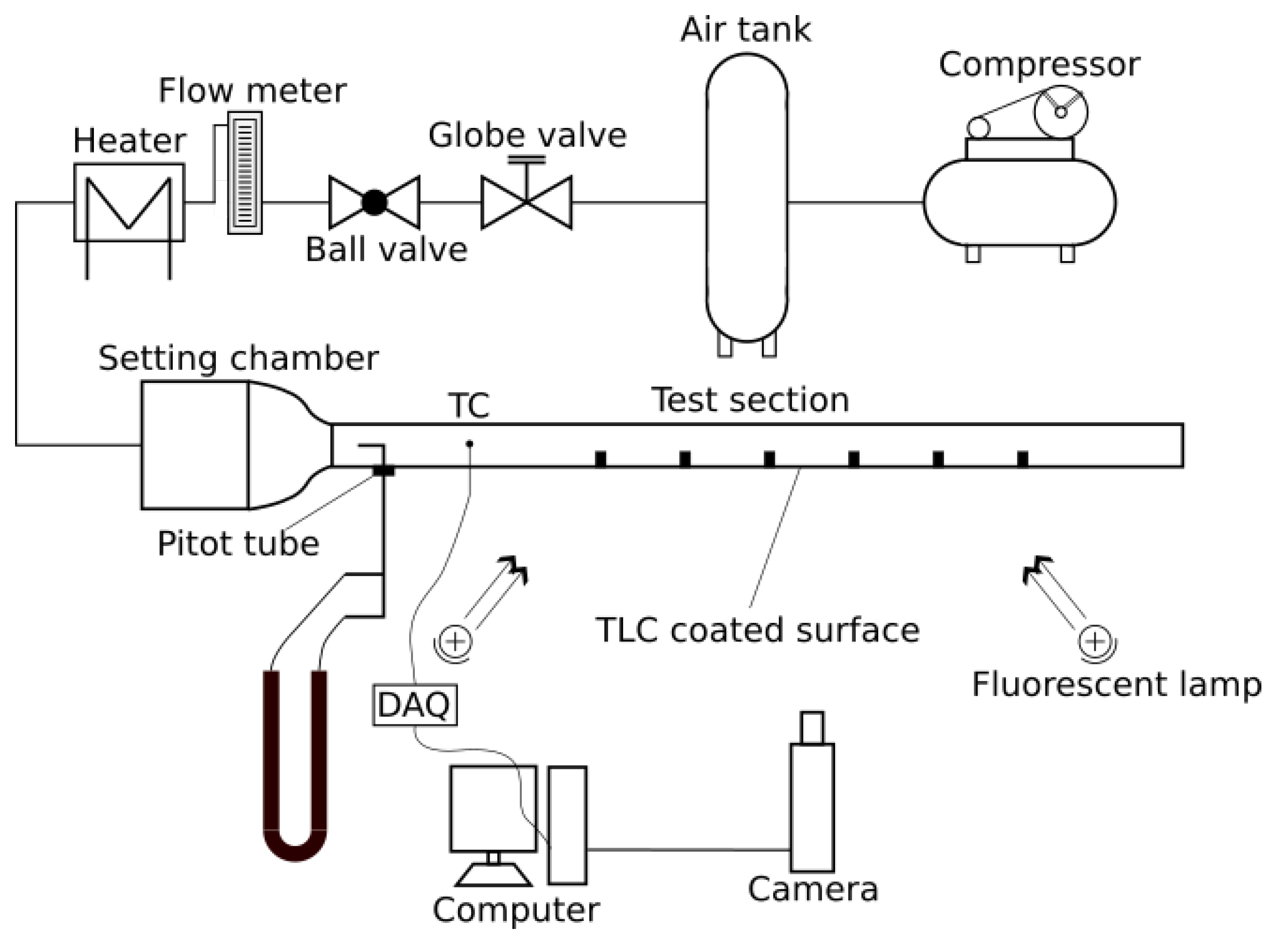
2.1. Test Rig

The heat transfer coefficient of a rectangular cooling channel with attached transverse ribs was studied on an internal cooling channel test rig comprised of an air supply system, test section, and corresponding data acquisition system. The schematic of the internal channel cooling test rig is shown in Figure 1. The airflow is controlled by a ball valve, while its flow rate is regulated by a globe valve and measured by a rotameter (Type LZB-50, Shanghai Tianchuan, Shanghai, China). Then, an electric heating section made of metal meshes is used to increase the air temperature. The settling chamber upstream of the test section is used to generate a uniform inflow for the test section. The walls of the test section are made of plexiglass, which is commonly used in transient TLC experiments. The length of the test section (L) is 500 mm and its cross-section is 50 × 30 mm 2 . The test wall is 10 mm thick, and the other three walls are 5 mm thick. Note that the thickness of the test wall should satisfy the requirement of the one-dimensional heat conduction assumption within the test duration time [25]. A thermocouple (Type K, CHAL-010-BW, Omega Engineering, Norwalk, CT, USA) is used to measure the reference gas temperature T g at the entrance of the test section. Before the experiment, the inner surface of the test plate was first sprayed with TLC (Type SPN100R35C1W, Hallcrest Ltd., West Yorkshire, UK), then with black conductive paint. During the experiment, a digital CMOS camera (200D, Canon, Tokyo, Japan) was utilized to record the color response at all locations on the test surface for further data processing.

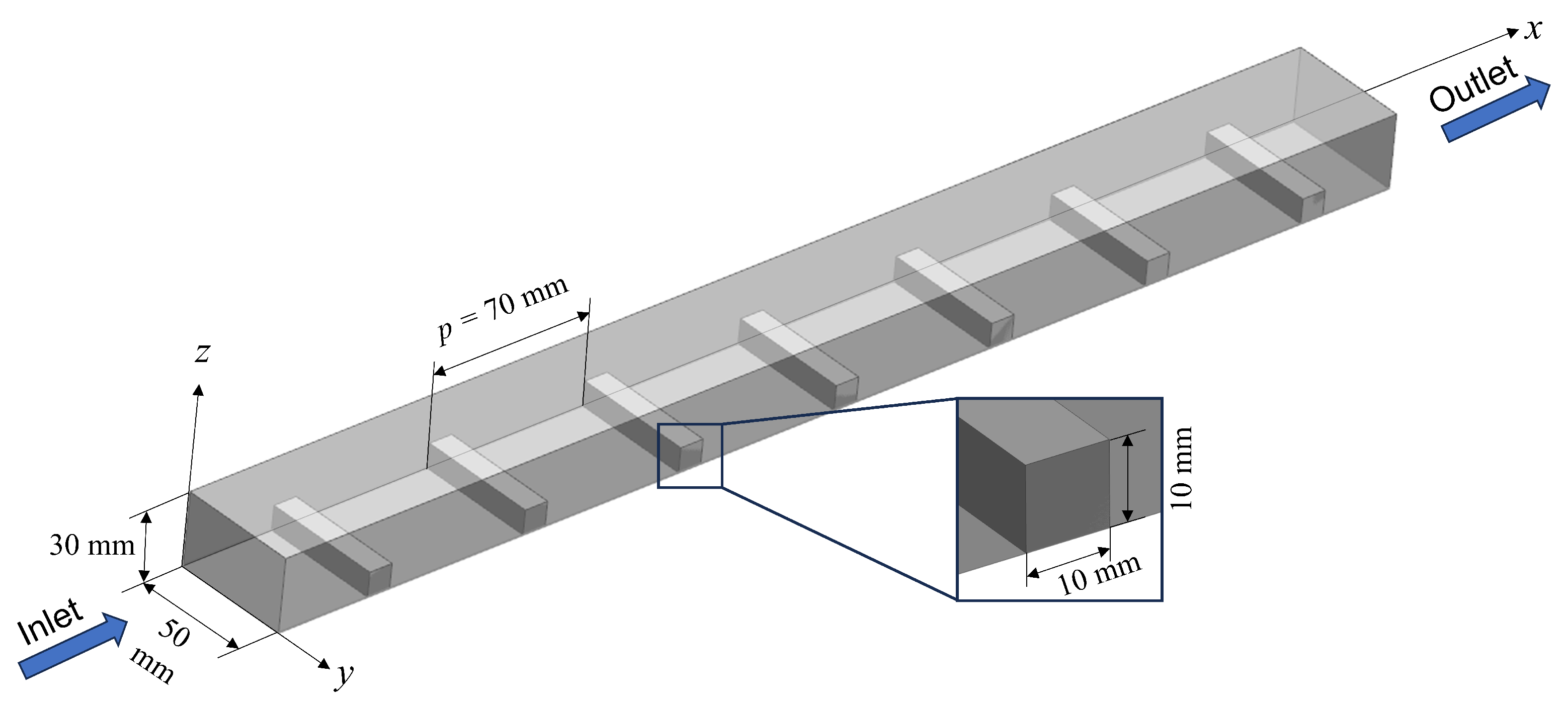
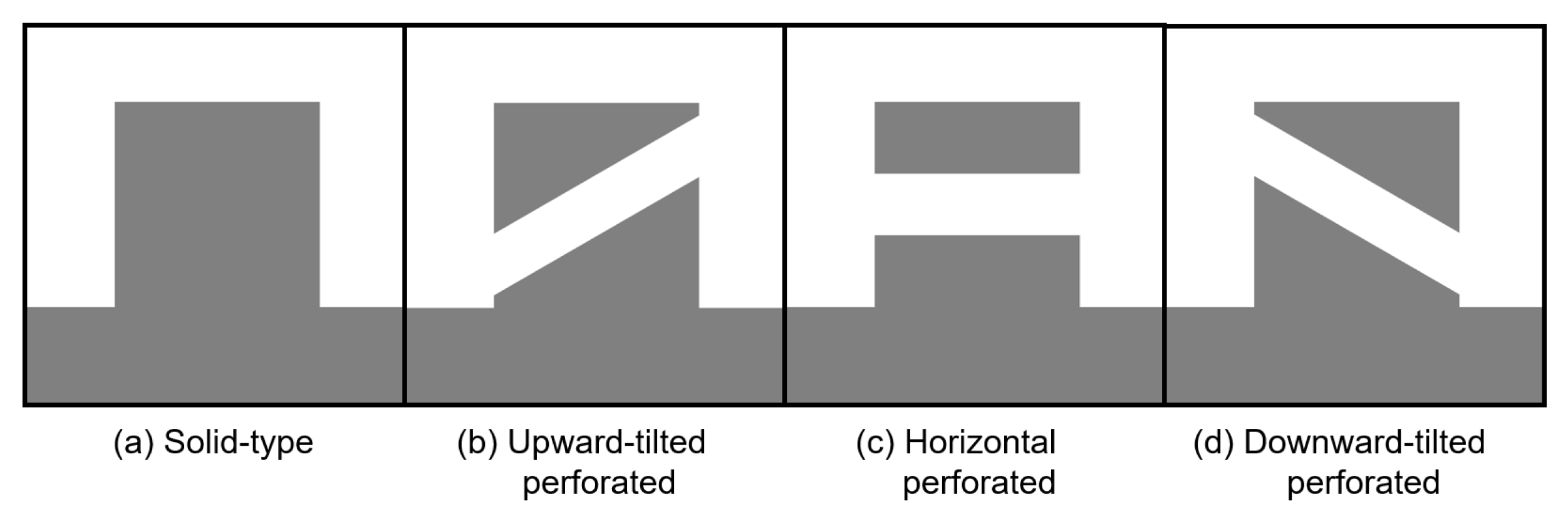
2.2. Rib Configuration

The present research includes solid-type transverse ribs and three types of perforated transverse ribs, namely, upward-tilted, horizontal, and downward-tilted. Solid-type ribs serve as the baseline for studying the thermal performance of perforated ribs. Figure 2 shows how transverse ribs are arranged on one inner wall (test surface) of the test section, with the cross-section of ribs being square. The ratio of pitch-to-height ( p / e ) of the ribs is 7, and the ratio of rib height to channel height ( e / H ) is 0.33. The ribs have the same width as the channel ( W = 50 mm). Perforated ribs have the same arrangement as solid-type ribs, as shown in Figure 2. For all types of perforated ribs, the diameter of perforation is 3 mm and the spacing between two adjacent holes is 5 mm. The open area ratio of the perforated ribs is calculated as follows:
r o a = n p r 2 π W e = 0.099
where n p = 7 is the number of perforations on a rib and r is the radius of perforation. The differences between the solid-type ribs and three types of perforated ribs are illustrated by their cross-sectional views in Figure 3. Additionally, Figure 4 shows a photograph indicating the color changes of the actual test section during the experiment.

2.3. Method for Determining the Heat Transfer Coefficient

In this work, the transient TLC single-color capture method is utilized to determine the heat transfer coefficient distribution on the test surface. As Han et al. [26] have provided a comprehensive description of this method, only a brief introduction is presented here.
A plexiglass test plate with sufficient thickness can be considered as a semi-infinite solid wall having a convective boundary condition. During the experiment, the heat penetration depth of the heated flow within a short duration time is small compared to the thickness of the plexiglass plate. According to assumption of semi-infinite one-dimensional heat conduction, the temperature field within the plate T ( χ , t ) is depicted by the governing equation (GE), boundary conditions (BCs), and initial condition (IC) as follows:
T ( χ , t ) t = k ρ c 2 T ( χ , t ) χ 2 , GE ,
k T ( 0 , t ) χ = h ( T w T g ) , BC at χ = 0 ,
T ( x , t ) = T 0 , BC at χ ,
T ( x , 0 ) = T 0 , IC at t = 0 ,
where χ represents the depth inside the plate and the parameters T 0 , T w , and T g are the initial temperature of the wall, real-time temperature of the test surface, and temperature of the gas flow, respectively. If T g is kept constant during the experiment, we can use Equations (2)–(5) to find that T w satisfies
T w T 0 T g T 0 = 1 exp ( β 2 ) erfc ( β ) = f ( β ) ,
where
β = h t / ( ρ c λ ) .
However, T g is generally not constant; in this case, the solution of T w can be obtained by treating the variations of T g as stepwise changes:
T w T 0 = ( T g , 0 T 0 ) × f ( β ) + j = 1 n { f [ h ( t τ j ) / ( ρ c λ ) ] × Δ T g , j }
where τ j and Δ T g , j are the variations of t and T g , respectively.
Before the experiment, the temperature corresponding to the appearance of a green color for TLC is determined by a calibration test, for which the initial temperature of the test section T 0 needs to be measured. During the experiment, a thermocouple is located at the test section inlet to measure T g . From the video of the color response, the time t corresponding to the appearance of green at each pixel location can be obtained using an image processing program. Then, in Equation (8), the heat transfer coefficient h is the only unknown parameter to be solved. Solving Equation (8) for h at all pixel locations generates the distribution of h on the test surface.

2.4. Uncertainty Analysis

The uncertainty analysis is conducted following the guidelines in [27]. For convenience, we denote
T w T 0 T g T 0 = θ w θ g = Θ .
Then, Equation (6) can be written as
Θ = f ( β ) .
From Equation (7), the uncertainty of h, denoted by B h , can be determined as follows:
( B h h ) 2 = ( B β β ) 2 + ( B t 2 t ) 2 + ( B ( ρ c λ ) 2 ρ c λ ) 2
where
( B β β ) 2 = 1 β 2 f 2 ( β ) { ( B T w θ w ) 2 + [ 1 f ( β ) ] 2 ( P T 0 θ w ) 2 + f 2 ( β ) ( B T g θ w ) 2 }
with f ( β ) = 2 β [ f ( β ) 1 ] + 2 π 1 / 2 . The uncertainty values of important variables are listed in Table 1. Finally, using Equations (11) and (12) and the data in Table 1, the percentage uncertainty of h is calculated to be 5.6 % .

3. Numerical Method

Three-dimensional simulations were conducted to analyze the flow features and underlying thermal performance variation mechanism of the perforated ribs. The numerical simulations in the present work were performed using the Fluent commercial CFD program. In this section, details about the governing equations, boundary conditions, discretization schemes, solution control, and mesh independence tests are presented.

3.1. Governing Equations

In these simulations, the working fluid air is considered as an incompressible Newtonian fluid and its physical properties are assumed to be temperature-independent. The effects of buoyancy and gravity forces are not considered. Therefore, the cooling flow in the rectangular channel is governed by the following RANS (Reynolds-averaged Navier–Stokes) equations and energy equation:
u ¯ i x i = 0 ,
( ρ u ¯ i u ¯ j ) x j = P ¯ x i + x j [ ( μ + μ t ) ( u ¯ i x j + u ¯ j x i ) ] ,
( ρ C p u ¯ i T ¯ ) x i = x i ( k + k t T ¯ x i ) .
In Equation (14), the turbulent viscosity μ t is modeled by the Shear Stress Transport (SST) k- ω model, as it has been well demonstrated to accurately predict the flow and heat transfer in a cooling channel [28,29]. The model details of SST k- ω can be found in [30]. In addition, the enhanced wall treatment method is utilized to model the turbulent quantities in the near-wall region.

3.2. Boundary Conditions and Discretization Schemes

The computational domain of the simulations is same as the test section shown in Figure 2. The boundaries of the computational domain include the inlet, outlet, test surface, and the other three walls. The inlet is set as a velocity inlet, with the velocity assigned according to the flow rate measured from the experiment and the coolant air temperature set to 400 K. The turbulent intensity at the inlet is estimated by a measurement-based scaling law [31] as follows:
I = 0.227 Re 0.100 .
An atmospheric pressure condition is applied at the channel outlet. All walls have the no-slip velocity condition. The ribbed test surface has a fixed temperature of 300 K, while other boundary walls are treated as adiabatic.

3.3. Discretization Schemes and Solution Control

For the gradient discretization scheme, we chose least squares cell-based gradient evaluation. To improve the accuracy of the simulations, second-order schemes were chosen for the spatial discretization of pressure, momentum, turbulent kinetic energy, turbulent dissipation rate, and energy equations. Because the computational geometry involves flowing through small-diameter perforations, double-precision calculation was enabled in Fluent, as it is necessary to resolve the pressure differences that drive the flow. The Semi-Implicit Method for Pressure-Linked Equations Consistent (SIMPLEC) scheme was chosen to solve the pressure–velocity coupling. As the convergence criterion, the residuals of the continuity, momentum, and energy equations are all required to be lower than 1 × 10 6 .

3.4. Mesh Independence Test

The computational domain of the test section was discretized using the tetra and prism mesh types. Because accurate simulations can only be obtained with sufficient resolution of the boundary layer, ten layers of prism mesh were arranged to be within the boundary layer and the total thickness of the prism layers was designed to be larger than the boundary layer. In addition, the maximum values of y + are smaller than 1, which complies with the requirement of enhanced wall treatment.
To ensure that the numerical results were independent of the domain discretization, a mesh independence test was conducted for the case of channel with solid-type ribs using different grid resolutions and at Re = 4000 . The distributions of h along the centerline of the test surface and between fourth and fifth rows at different grid resolutions and Re numbers are shown in Figure 5. It can be seen that the mesh independence of the h profiles can be ensured by a grid with 1.1 × 10 7 cells. Therefore, such a grid resolution was adopted in all our simulations. Additionally, the corresponding results of h obtained from TLC measurements are presented in the figure for comparison with the numerical simulation results. This comparison shows that the numerical simulation results match the experimental results well, accurately predicting h in most areas. However, certain regions show some deviation between the numerical simulation and experimental results. Considering that the role of numerical simulation in this paper is to explain the differences in heat transfer performance, the accuracy of the numerical simulation can be considered acceptable.

4. Data Reduction

The dimensionless parameters used in this study are introduced in this section. First, the working conditions of the cooling channel are set up according to the Reynolds number of the cooling airflow, defined by the hydraulic diameter D h of the channel as
Re = U ¯ D h υ = Q ˙ W H υ 2 ( W + H ) W H ,
where U ¯ is the average velocity of the airflow computed from the measured volume flow rate Q ˙ .
We utilize the following local and average Nusselt numbers to assess the cooling performance of the test surface:
Nu = h D h k ,
Nu ¯ = h ¯ D h k ,
where h and h ¯ are the local and surface-averaged heat transfer coefficients, respectively. Note that in both the experiments and simulations the reference temperature used to determine the heat transfer coefficient was the channel inlet temperature. The surface average Nusselt numbers were then further normalized using the average Nusselt number Nu 0 of the surface of a smooth channel with the same dimension:
Nu ¯ * = Nu ¯ / Nu 0 .
The flow friction of the channel is characterized by the friction factor:
f = 2 L / D h Δ P ρ U ¯ 2
where Δ P is the pressure drop of the test section. Further, the normalized friction factor is defined as
f * = f / f 0 ,
where f 0 is the friction factor of a smooth circular tube with the same hydraulic diameter at the same Reynolds number. The values of Nu ¯ 0 and f 0 were computed using the Dittus–Boelter correlation [32] and the Blasius solution, provided in Equations (23) and (24), respectively:
Nu 0 = 0.023 Re 0.8 Pr 0.4 m
f 0 = 0.079 Re 0.25 ,

5. Results and Discussion

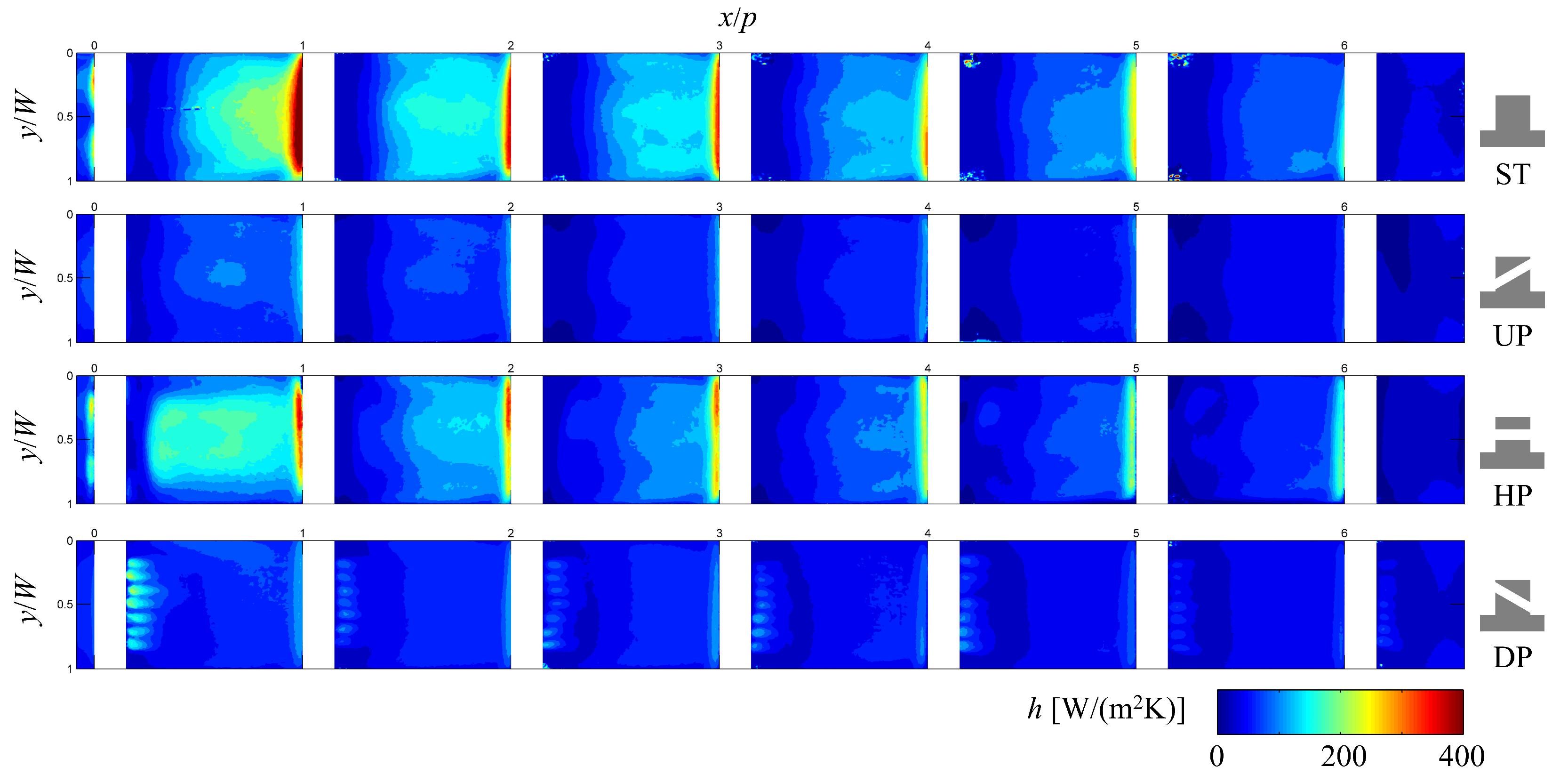
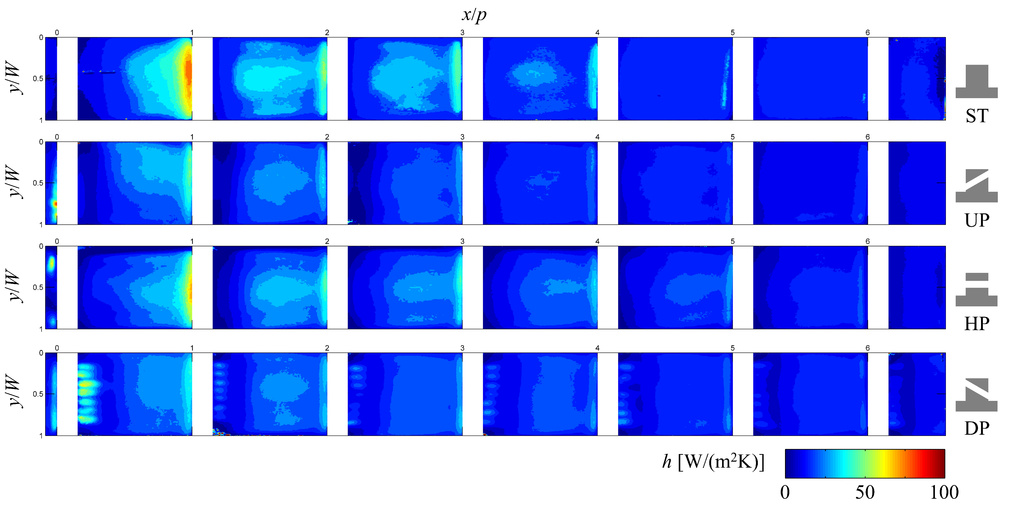
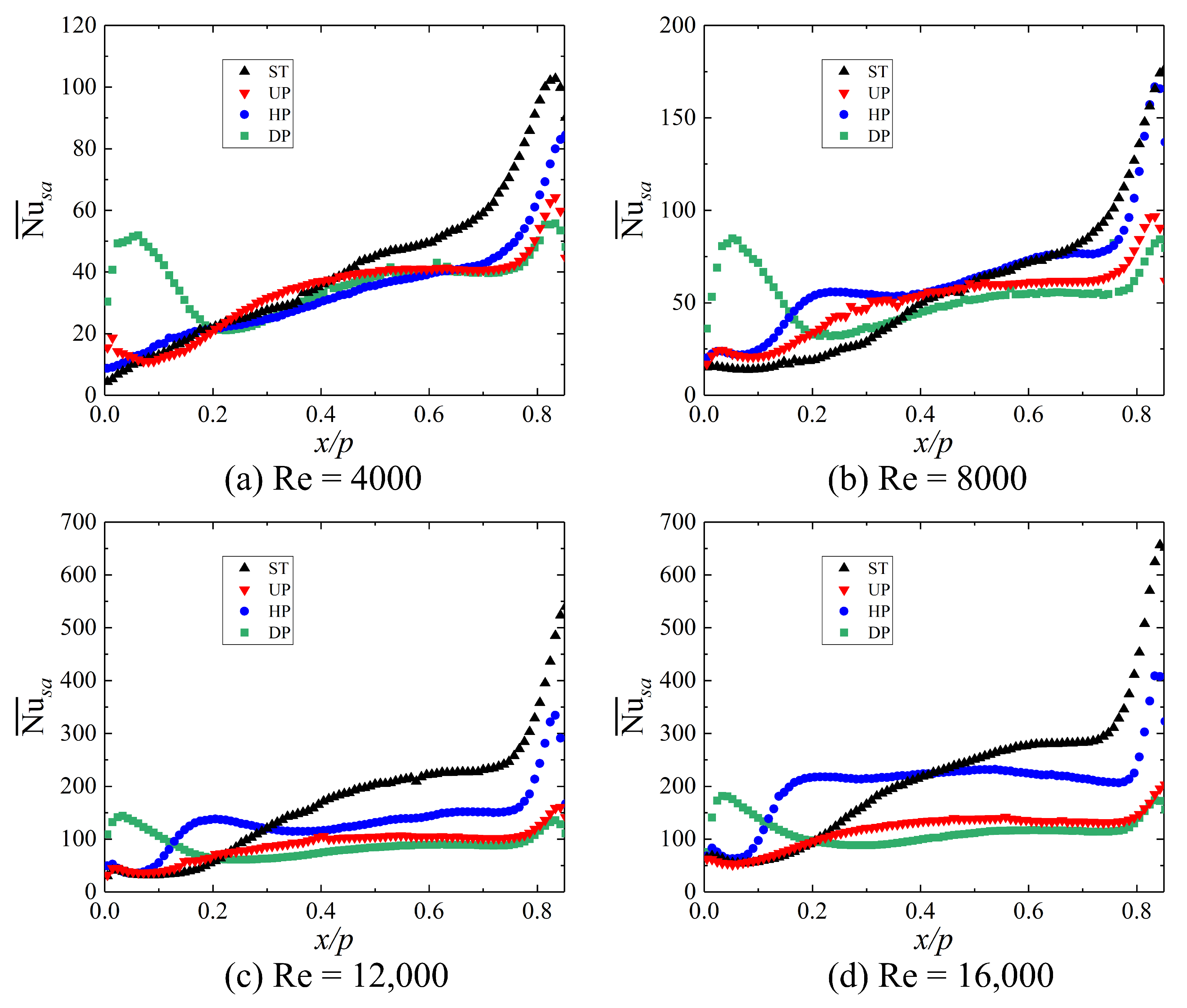
5.1. Heat Transfer Characteristics

The heat transfer characteristics of solid-type ribs and three types of perforated ribs obtained from the transient TLC experiment are presented and discussed in this subsection.
Figure 6 shows the contours of the heat transfer coefficient h on the test surface for different ribs at Re = 16,000. It can be seen that in all cases the heat transfer behind the first rib is stronger than that behind subsequent ribs. For solid-type (ST) ribs, following the general theory [33], there exists a typical recirculation zone downstream of each rib where the heat transfer is weak. Downstream of the recirculation zone is a reattachment zone where heat transfer is improved by the reattachment flow [33]. In the ST case, the highest value of h can be found in the region upstream of the next rib, where heat transfer is enhanced by flow impingement and acceleration due to blockage. For upward-tilted perforated (UP) ribs, the recirculation zone with weak heat transfer is slightly enlarged by the UP ribs compared to the ST case, while flow reattachment and associated heat transfer enhancement are severely weakened compared with the ST case. For horizontal perforated (HP) ribs, the recirculation behind the rib is partly diminished by the flow through the holes [16], which improves the heat transfer at the recirculation zone downstream of the rib. However, the heat transfer coefficient downstream of the recirculation zone is lower than that of ST ribs. This is caused by the interaction between flow through the holes and main flow along with the decrease of the block ratio in the channel. In addition, HP ribs exhibit pronounced heat transfer enhancement behind the first rib compared to subsequent ribs, with inferior performance behind subsequent ribs compared to ST ribs. Lastly, for downward-tilted perforated (DP) ribs, heat transfer in the region downstream of the ribs is apparently enhanced by impingement of the ‘jet-like’ flow through the holes [17]. Along the main flow direction, the heat transfer coefficient first decreases, then increases. Except for the region behind the ribs, heat transfer in the DP case is weaker than in the ST and HP cases. The contours of the heat transfer coefficient for different ribs at Re = 4000 are shown in Figure 7. It can be seen that the distribution of h in the ST, UP, and DP cases at Re = 4000 have similar patterns as those at Re = 16,000. However, in the case of HP ribs the distribution patterns are different from those at high Re, while the thermal performance of the HP ribs is close to but slightly weaker than the ST ribs. Here, the performance differences of HP ribs under two Reynolds numbers need to be analyzed according to the flow field details.
To better compare the heat transfer characteristics of different ribs, the spanwise-averaged Nusselt number Nu ¯ s a for different ribs are calculated from the results of transient TLC experiments using the following expression:
Nu ¯ s a = 0 W Nu ( y ) d y W .
Figure 8 presents and compares the profiles of Nu ¯ s a along x and between the first and second ribs. For solid ribs, it can be seen that the Nusselt number increases with the distance from the trailing edge of the rib. This trend for ST ribs is due to the upstream flow separation and the downstream airflow reattachment and impingement. Perforation of the rib completely alters the distribution pattern of the Nusselt number behind the rib. The effects of horizontal perforation become notable as Re 8000 ; the reattachment zone is extended upstream, enlarging its area and reducing the size of the low heat transfer coefficient region behind the rib. At high Reynolds numbers (Re = 16,000), horizontally perforated ribs result in higher and more uniform Nusselt numbers across all regions except in the immediate vicinity behind the rib. From this perspective, it can be considered that horizontally perforated ribs exhibit an optimal heat transfer enhancement effect. Ribs with downward-tilted perforations (DP) shift the location of the strongest heat transfer from before the rib to behind it; except for the region behind the rib, the heat transfer enhancement effect is relatively weaker in other regions. Ribs with upward-tilted perforations only slightly increase the size of the reattachment zone, resulting in the poorest overall heat transfer enhancement effect.
Figure 9 shows the variation of area-average Nusselt number Nu ¯ behind ribs 1–7 with the Re for different ribs. It can be observed that for four different rib structures, the surface-averaged Nusselt numbers increase significantly with increasing Reynolds number. Solid ribs have the highest Nu ¯ , followed by HP ribs, while the Nu ¯ of DP and UP ribs are close to each other and have the smallest values. At low Reynolds numbers, the differences in Nu ¯ among different ribs are not significant. At high Reynolds numbers, there are noticeable differences in Nu ¯ among different ribs due to variations in the resulting flow field characteristics. Therefore, the subsequent analysis utilizes the numerical simulation results to examine discrepancies in flow field characteristics and flow details caused by different rib structures.

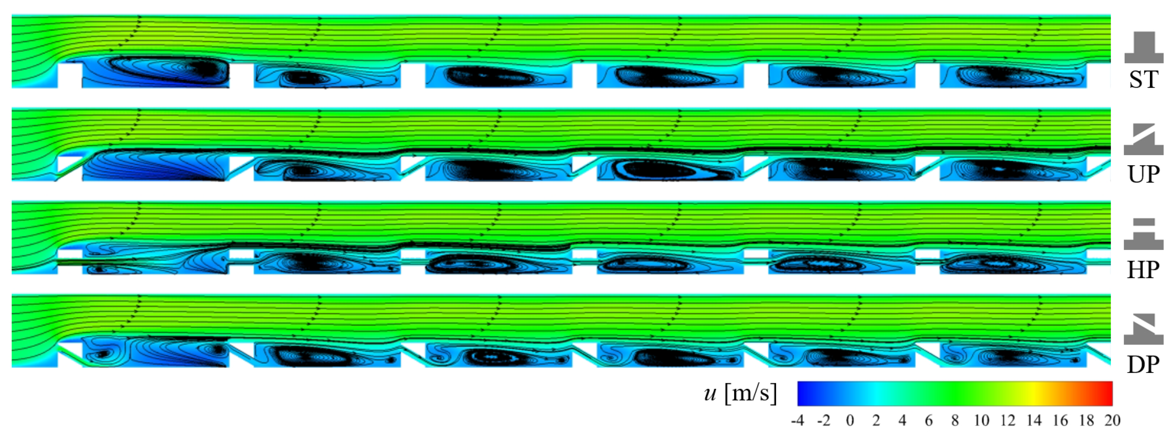
5.2. Flow Structures

The flow fields obtained from our numerical simulations are studied here to better understand the effects of rib configuration on the flow friction and heat transfer characteristics. Figure 10 and Figure 11 present the contours of axial velocity u and streamlines on the vertical middle cross-sections of all cases at Re = 4000 and Re = 16,000, respectively. It can be seen that all three types of perforated ribs are permeable under the studied operating conditions. It is also possible to see that the flow field structures behind the first rib differ significantly from those behind the second and subsequent ribs due to differences in the incoming flow conditions. This conclusion holds true for all four different rib structures and both tested Reynolds numbers. For ST ribs, a large vortex is formed behind the first rib, which enhances heat transfer by making the airflow impinge on the region ahead of the second rib; however, the vortex flow separates downstream of the rib, which causes poor heat transfer. Behind the second and subsequent solid-type ribs, the vortices still exist but are diminished, allowing the airflow to reattach and enhancing heat transfer in the region ahead of the ribs. It can also be seen that when the Re increases, the size of the vortices decreases slightly.
In the case of UP ribs, the airflow is bifurcated behind the first rib, with one portion flowing over the rib and the other portion flowing towards the perforations. The nearby wall region behind the rib is covered by the recirculation zone. Behind the second rib and subsequent ones, the air flowing through the upward-tilted perforations can couple with the recirculation vortex behind the ribs, resulting in a larger coverage area of the vortex. The airflow passing through the perforations causes the vortex airflow to deviate from the direction of impingement on the wall while, obstructing the reattachment of the main stream. This diminishes the heat transfer enhancement effects due to airflow impingement and reattachment, which is consistent with the experimental results shown in Figure 6 and Figure 7. For HP ribs, the airflow passing through the perforations results in an apparent reduction in the size of the recirculation vortex behind the first rib [18], then flows towards the wall and bifurcates afterwards, flowing either over the ribs or through the horizontal perforation. The airflow passing through the perforations enhances heat transfer by scouring the wall surface; this heat transfer enhancement mechanism is more pronounced at Re = 16,000 compared to at Re = 4000. These results explains the heat transfer coefficient distribution shown in Figure 6 and Figure 7. Behind subsequent HP ribs, the airflow passing through the perforations compresses the height of the recirculation vortex and decreases the size of the separation region behind ribs [18]. However, the perforations on the subsequent ribs and the smaller rib pitch used in this study make it difficult for the airflow to reattach, thereby weakening the heat transfer performance compared to ST ribs. Lastly, in the case of DP ribs, the airflow behind the first rib impinges in the region downstream of the rib, causing detachment of the vortex from the wall followed by the formation of large separation vortices ahead of the rib. Behind the subsequent ribs, the airflow causes detachment of the recirculation vortices from behind the rib and decreases their sizes; however, airflow then separates ahead of the next rib due to the higher inlet position of the perforations. This separation is detrimental to heat transfer enhancement. In contrast, the larger pitch between the ribs in previous studies [17,18] prevented this airflow separation; in these cases, the reduced size of the recirculation vortex and earlier reattachment of the airflow were beneficial for heat transfer enhancement. The difference in heat transfer performance of the HP and DP ribs compared to the conclusions in [17,18] is primarily due to this variation in rib pitch.

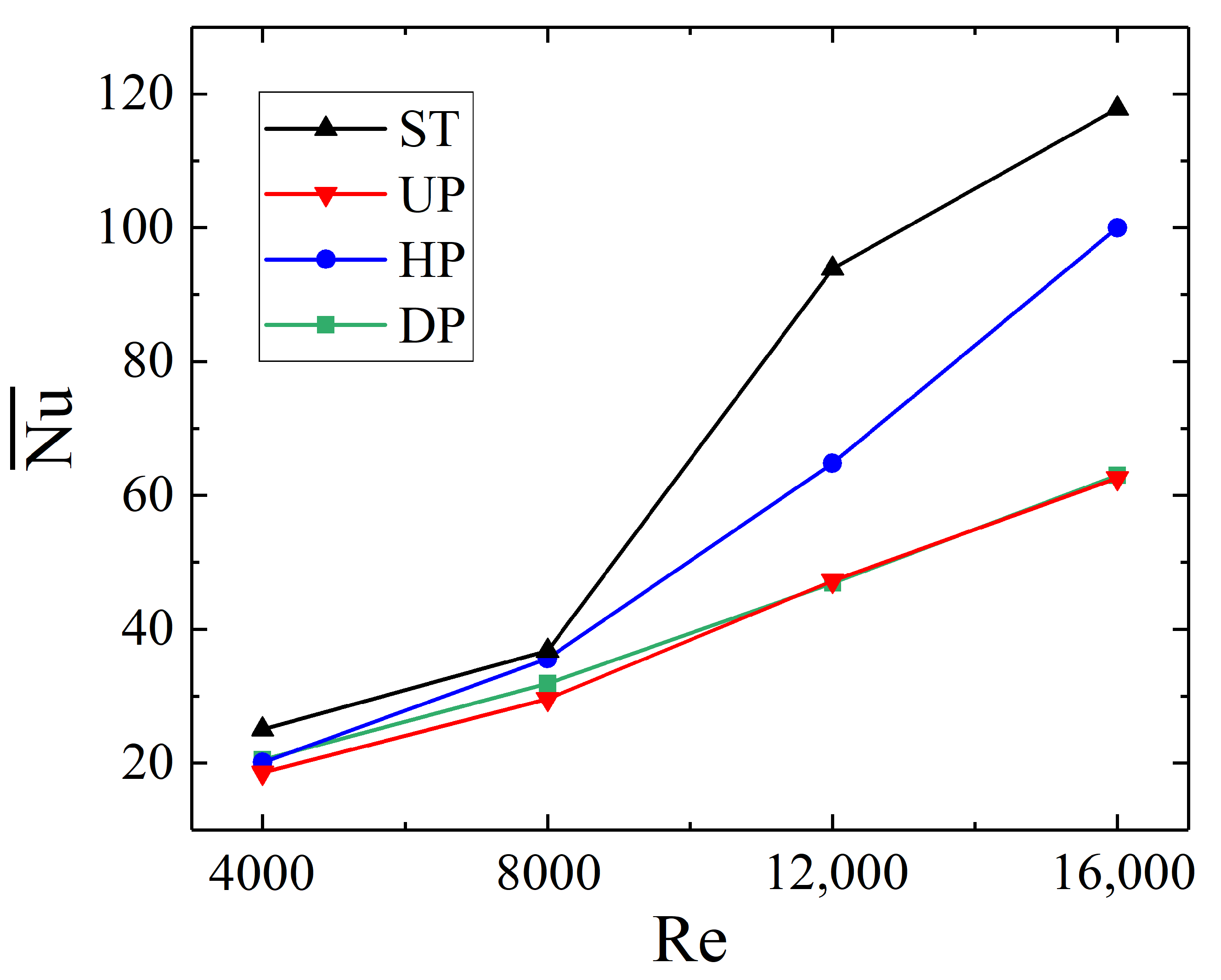
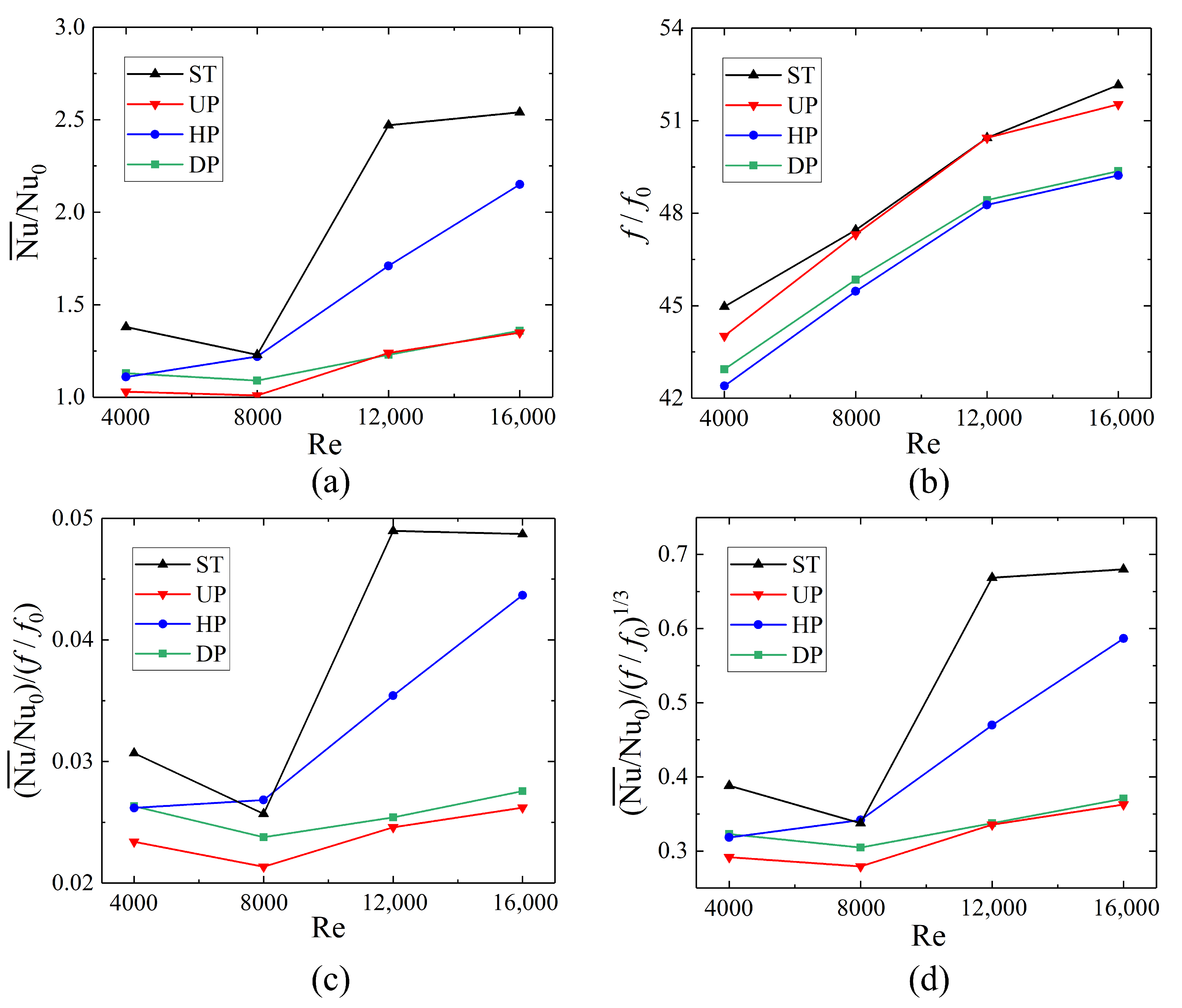
5.3. Thermal Performance

For internal cooling of turbine blades, both the heat transfer performance and flow resistance are important factors to consider. A balance between these two is usually achieved by taking the thermal performance index into account. Hence, in order to comprehensively assess the impact of the perforation direction of transverse ribs on thermal hydraulic performance, we have further calculated and compared several thermal parameters, including the normalized Nusselt number ( Nu ¯ / Nu 0 ), normalized friction factor ( f / f 0 ), and two different thermal performance indices ( η 11 = [ Nu ¯ / Nu 0 ] / [ f ¯ / f 0 ] and η 13 = [ Nu ¯ / Nu 0 ] / [ f ¯ / f 0 ] 1 / 3 ), as shown in Figure 12.
Figure 12a compares the normalized Nusselt numbers of the four different rib configurations studied in this work. It can be observed that except for the HP rib, the normalized Nusselt numbers of the other three types of ribs all decrease initially as the Reynolds number increases up to 8000, then increase with further increases in the Reynolds number. For the HP rib, the Nusselt number keeps increasing with the increase in Re.
Figure 12b presents a comparison of the normalized friction factors of the four different rib configurations in order to analyze the differences in their flow resistance characteristics. It can be seen that the ST rib exhibits the highest friction factor, consistent with its having the best thermal performance. The friction factor of the UP rib is slightly lower than that of the ST rib, but higher than those of the DP and HP ribs. From the flow field analysis, it is evident that the coupling between the airflow passing through the UP and the separation vortices strengthens the separation vortices. Among the four ribs, the HP rib exhibits the lowest friction factor. The pressure loss of DP ribs is greater than that of HP ribs, which is consistent with the conclusions in [18].
Two different thermal performance indices, η 11 and η 13 , were calculated to evaluate the thermohydraulic performance of different rib configurations. Both of these indices simultaneously consider the heat transfer coefficient and pressure loss, as shown in Figure 12c,d. The trends in the variations of the two thermal performance indices with Re are consistent with each other for the four tested rib configurations. With Re = 4000, the thermal performance index values of the ST ribs are the highest, followed by the HP and DP ribs, which are close to each other, then the UP ribs with the lowest value. At a Reynolds number of 8000, the thermal performance of the HP ribs outperforms that of the ST ribs due to the similar heat transfer coefficients and lower friction coefficients of the horizontal perforated ribs. As the Re increases to 12,000, the indices η 11 and η 13 of the ST rib become significantly higher than those of the HP rib, while the indices of the HP rib are higher than those of the other two cases. As the Reynolds number is continuously increased, the thermal performance of the HP rib grows significantly more than that of the ST rib, resulting in closer thermal performance indices. The thermal performance indices of the UP and the DP ribs show no significant increases. Note that the thermal performance index only considers the area-averaged Nusselt number, and does not account for the distribution pattern of the Nusselt numbers on the surface. In this study, the thermal performance indices of HP ribs are lower than those of ST ribs in most cases, which contradicts the conclusions in [16]. This is because the work of [16] only included two rows of perforated ribs, and only considered the heat transfer behind the first row. Differences in the Nusselt number distribution can lead to variations in thermal stress within the blade material. The creeping fatigue effect of thermal stress can result in turbine blade failure. Therefore, subsequent research should investigate the thermal stress distribution of turbine blades with corresponding internal cooling structures using a fluid–structure–thermal coupling method [34].

6. Conclusions

This paper has investigated the turbulent flow details and thermal hydraulic performance of a rectangular cooling channel with transverse perforated ribs attached on one wall in order to study the effects of the perforation directions on the thermohydraulic performance of the cooling channel. Solid-type ribs were also studied as a baseline for evaluating the thermal performance of various types of perforated ribs. The transient thermographic liquid crystal technique and numerical simulations were adopted to acquire the heat transfer coefficient distribution and turbulent flow fields in the cooling channel with Re values ranging from 4000 to 16,000. The following conclusions can be drawn from our results:
(1)
Due to low frictional resistance and relatively high heat transfer coefficients, horizontal perforated ribs exhibit the highest thermal performance index at Re = 8000 , while solid-type ribs have the highest thermal performance index under other operating conditions.
(2)
Horizontal perforated ribs can compress the recirculation zone behind the ribs, reducing channel pressure loss, while the airflow passing through the horizontal perforations enhances heat transfer behind the ribs. At high Reynolds numbers, the use of horizontal perforated ribs can reduce channel pressure loss without significantly compromising heat transfer enhancement.
(3)
Changing the direction of rib perforation can induce complex flow structures behind the rib, resulting in various effects on flow and heat transfer. Upward-tilted perforated ribs increase flow friction and diminish heat transfer compared to horizontal perforated ribs. Downward-tilted perforated ribs direct the airflow to impinge directly on the area behind the rib, enhancing local heat transfer behind the rib. However, the overall heat transfer performance of downward-tilted perforated ribs is not as notable as that of horizontal perforated ribs.

Author Contributions

Conceptualization, W.Q. and P.W.; methodology, Q.M. and S.R.; software, P.W. and S.Y.; validation, S.Y. and R.S.; investigation, W.Q. and R.S.; resources, P.W.; data curation, R.S., Q.M., S.Y. and S.R.; writing—original draft preparation, W.Q.; writing—review and editing, P.W.; visualization, W.Q. and R.S.; supervision, P.W.; project administration, P.W.; funding acquisition, W.Q. and P.W. All authors have read and agreed to the published version of the manuscript.

Funding

This research was funded by the Natural Science Foundation of Jiangsu Province under grant number BK20230532.

Data Availability Statement

Data will be made available on request.

Acknowledgments

The financial support from the Natural Science Foundation of Jiangsu Province (Grant No. BK20230532) is gratefully acknowledged.

Conflicts of Interest

The authors declare no conflicts of interest.

Nomenclature

cspecific heat capacity, J / [ kg · K ]
D h hydraulic diameter, m
erib height, m
ffriction factor
Hchannel height, m
hheat transfer coefficient, W / [ m 2 · K ]
kthermal conductivity, W / [ m · K ]
Lchannel length, m
N u Nusselt number
n p number of perforations on a rib
prib pitch, m
Q ˙ volume flow rate, m 3 / s
Re Reynolds number
r o a open area ratio of perforated ribs
rradius of a perforation, m
Ttemperature, K
ttime, s
U ¯ mean axial velocity, m / s
Wchannel width, m
Pr Prandtl number
Greek Symbols
Δ P Pressure drop, Pa
ρ density, kg / m 3
ν kinematic viscosity, m 2 / s
η thermal index
Subscripts
ggas
wwall
s a spanwise-averaged
Abbreviations
CFDcomputational fluid dynamics
TLCthermographic liquid crystal
DPdownward-tilted perforated ribs
HPhorizontal perforated ribs
UPupward-tilted perforated ribs
STsolid-type ribs

References

  1. Zhang, F.; Song, H.; Liu, C.L.; Liu, H.Y.; Ye, L.; Zhou, T.L.; Li, B.R. Study on the film cooling effectiveness of shaped holes in the suction surface gill region of the turbine blade. Int. J. Therm. Sci. 2023, 184, 107977. [Google Scholar] [CrossRef]
  2. Li, L.; Liu, C.L.; Xu, Z.P.; Zhu, H.R.; Zhang, F. Experimental and numerical research on film cooling characteristics on the compound angle hole. Phys. Fluids 2022, 34, 125128. [Google Scholar] [CrossRef]
  3. Fan, X.J.; Li, L.; Zou, J.S.; Zhou, Y.Y. Cooling methods for gas turbine blade leading edge: Comparative study on impingement cooling, vortex cooling and double vortex cooling. Int. Commun. Heat Mass Transf. 2019, 100, 133–145. [Google Scholar] [CrossRef]
  4. Li, G.; Li, A.; Zhang, S.; Wang, C.; Lu, X. Film Cooling Performance on a Turbine Blade With Subregional Compound Angle. ASME J. Heat Mass Transf. 2024, 146, 053801. [Google Scholar] [CrossRef]
  5. Nourin, F.N.; Amano, R.S. Review of gas turbine internal cooling improvement technology. ASME J. Energy Resour. Technol. 2021, 143, 080801. [Google Scholar] [CrossRef]
  6. Dinh, C.T.; Nguyen, T.M.; Vu, T.D.; Park, S.G.; Nguyen, Q.H. Numerical investigation of truncated-root rib on heat transfer performance of internal cooling turbine blades. Phys. Fluids 2021, 33, 076104. [Google Scholar] [CrossRef]
  7. Su, W.J.; Huang, T.H.; Liu, Y.H. Heat transfer and friction in trapezoidal channels with X-shaped ribs. Int. J. Therm. Sci. 2021, 164, 106871. [Google Scholar] [CrossRef]
  8. He, P.; Mader, C.A.; Martins, J.R.R.A.; Maki, K.J. Aerothermal optimization of a ribbed U-bend cooling channel using the adjoint method. Int. J. Heat Mass Transf. 2019, 140, 152–172. [Google Scholar] [CrossRef]
  9. Ran, S.; Zhang, P.; Rao, Y. Numerical study of heat transfer and flow structure over channel surfaces featuring miniature V rib-dimples with various configurations. Int. J. Therm. Sci. 2022, 172, 107342. [Google Scholar] [CrossRef]
  10. Chung, H.; Park, J.S.; Park, S.; Choi, S.M.; Rhee, D.H.; Cho, H.H. Augmented heat transfer with intersecting rib in rectangular channels having different aspect ratios. Int. J. Heat Mass Transf. 2015, 88, 357–367. [Google Scholar] [CrossRef]
  11. Chen, I.L.; Sahin, I.; Wright, L.M.; Han, J.C.; Krewinkel, R. Heat Transfer in a rotating, blade-Shaped, two-pass cooling channel with a variable aspect ratio. J. Turbomach. 2022, 144, 021011. [Google Scholar] [CrossRef]
  12. Zhang, D.W.; Li, H.W.; Tian, Y.T.; You, R.Q.; Zhang, X.J.; Wu, A. Effects of a high Reynolds number and rotation on the leading-edge heat transfer of a ribbed cooling channel with a cross-section consisting of a semicircle and a rectangle. Int. J. Heat Mass Transf. 2022, 188, 122646. [Google Scholar] [CrossRef]
  13. Wang, X.; Xu, H.; Wang, J.; Song, W.; Wang, L. High pressure turbine blade internal cooling in a realistic rib roughened two-pass channel. Int. J. Heat Mass Transf. 2021, 170, 121019. [Google Scholar] [CrossRef]
  14. Hwang, J.J.; Liou, T.M. Heat transfer in a rectangular channel with perforated turbulence promoters using holographic interferometry measurement. Int. J. Heat Mass Transf. 1995, 38, 3197–3207. [Google Scholar] [CrossRef]
  15. Sara, O.N.; Pekdemir, T.; Yapici, S.; Yilmaz, M. Heat-transfer enhancement in a channel flow with perforated rectangular blocks. Int. J. Heat Fluid Flow 2001, 22, 509–518. [Google Scholar] [CrossRef]
  16. Liu, J.; Hussain, S.; Wang, W.; Xie, G.; Sundén, B. Experimental and numerical investigations of heat transfer and fluid flow in a rectangular channel with perforated ribs. Int. Commun. Heat Mass Transf. 2021, 121, 105083. [Google Scholar] [CrossRef]
  17. Nuntadusit, C.; Wae-hayee, M.; Bunyajitradulya, A.; Eiamsa-ard, S. Thermal visualization on surface with transverse perforated ribs. Int. Commun. Heat Mass Transf. 2012, 39, 634–639. [Google Scholar] [CrossRef]
  18. Javanmard, S.; Ashrafizadeh, A. A comparative numerical study on heat transfer and pressure drop characteristics of perforated ribs. Int. J. Therm. Sci. 2023, 191, 108373. [Google Scholar] [CrossRef]
  19. Buchlin, J.M. Convective heat transfer in a channel with perforated ribs. Int. J. Therm. Sci. 2002, 41, 332–340. [Google Scholar] [CrossRef]
  20. Karwa, R.; Maheshwari, B. Heat transfer and friction in an asymmetrically heated rectangular duct with half and fully perforated baffles at different pitches. Int. Commun. Heat Mass Transf. 2009, 36, 264–268. [Google Scholar] [CrossRef]
  21. El Habet, M.A.; Ahmed, S.A.; Saleh, M.A. Thermal/hydraulic characteristics of a rectangular channel with inline/staggered perforated baffles. Int. Commun. Heat Mass Transf. 2021, 128, 105591. [Google Scholar] [CrossRef]
  22. Shevchuk, I.V.; Jenkins, S.C.; Weigand, B.; von Wolfersdorf, J.; Neumann, S.O.; Schnieder, M. Validation and Analysis of Numerical Results for a Varying Aspect Ratio Two-Pass Internal Cooling Channel. J. Heat Transf. 2011, 133, 051701. [Google Scholar] [CrossRef]
  23. Liu, C.; Wang, Z.; Zhang, Z.W. Investigation on Heat Transfer Augmentation in a InnerCooling Passage with Triangular V-Shaped and Inverse V-Shaped Ribs. J. Propuls. Technol. 2019, 40, 2040–2049. [Google Scholar] [CrossRef]
  24. Haemisch, J.; Suslov, D.; Oschwald, M. Experimental Study of Methane Heat Transfer Deterioration in a Subscale Combustion Chamber. J. Propuls. Power 2019, 35, 819–826. [Google Scholar] [CrossRef]
  25. Wagner, G.; Kotulla, M.; Ott, P.; Weigand, B.; von Wolfersdorf, J. The Transient Liquid Crystal Technique: Influence of Surface Curvature and Finite Wall Thickness. J. Turbomach. 2005, 127, 175–182. [Google Scholar] [CrossRef]
  26. Han, J.C.; Dutta, S.; Ekkad, S. Gas Turbine Heat Transfer and Cooling Technology; CRC Press: Boca Raton, FL, USA, 2012. [Google Scholar]
  27. Bich, W. Revision of the ‘guide to the expression of uncertainty in measurement’. Why and how. Metrologia 2014, 51, S155. [Google Scholar] [CrossRef]
  28. Zhang, F.; Wang, X.; Li, J. Effects of coolants on the flow and heat transfer characteristics in a non-rotating and rotating two-pass rectangular channel. Int. J. Heat Mass Transf. 2015, 91, 390–400. [Google Scholar] [CrossRef]
  29. Zhang, Q.; Wang, T.; Hou, Q.; Song, K.; Hu, W.; Wu, X. Thermal hydraulic performance augmentation by petal-shaped ribs in a two-pass cooling channel. Case Stud. Therm. Eng. 2022, 40, 102542. [Google Scholar] [CrossRef]
  30. Menter, F.R. Two-equation eddy-viscosity turbulence models for engineering applications. AIAA J. 1994, 32, 1598–1605. [Google Scholar] [CrossRef]
  31. Russo, F.; Basse, N.T. Scaling of turbulence intensity for low-speed flow in smooth pipes. Flow Meas. Instrum. 2016, 52, 101–114. [Google Scholar] [CrossRef]
  32. Lienhard, J.H. A Heat Transfer Textbook; Courier Corporation: North Chelmsford, MA, USA, 2013. [Google Scholar]
  33. Lee, C.; Abdel-Moneim, S. Computational analysis of heat transfer in turbulent flow past a horizontal surface with two-dimensional ribs. Int. Commun. Heat Mass Transf. 2001, 28, 161–170. [Google Scholar] [CrossRef]
  34. Yeranee, K.; Rao, Y.; Xu, C.; Zhang, Y.; Su, X. Turbulent Flow Heat Transfer and Thermal Stress Improvement of Gas Turbine Blade Trailing Edge Cooling with Diamond-Type TPMS Structure. Aerospace 2024, 11, 37. [Google Scholar] [CrossRef]
Figure 1. Schematic of the internal cooling channel test rig.
Aerospace 11 00675 g001
Figure 2. Schematic of rib configurations.
Aerospace 11 00675 g002
Figure 3. Cross-sectional views of different ribs.
Aerospace 11 00675 g003
Figure 4. Photograph of the test section during the experiment.
Aerospace 11 00675 g004
Figure 5. Comparison of h distributions along the centerline of the test surface and between the fourth and fifth rows at different grid resolutions and Re = 4000 .
Aerospace 11 00675 g005
Figure 6. Heat transfer coefficient distributions on the test surface for different rib configurations at Re = 16,000.
Aerospace 11 00675 g006
Figure 7. Heat transfer coefficient distributions on the test surface for different rib configurations at Re = 4000.
Aerospace 11 00675 g007
Figure 8. Comparisons of the spanwise-averaged Nusselt number profiles of different cases at different Re: (a) Re = 4000, (b) Re = 8000, (c) Re = 12,000, and (d) Re = 16,000.
Aerospace 11 00675 g008
Figure 9. Area-average Nusselt number behind different rib configurations at Re = 4000–16,000.
Aerospace 11 00675 g009
Figure 10. Axial velocity contours and streamlines on the vertical middle cross-section ( z = 0.5 W ) at Re = 4000 for different rib structures.
Aerospace 11 00675 g010
Figure 11. Axial velocity contours and streamlines on the vertical middle cross-section ( z = 0.5 W ) at Re = 16,000 for different rib structures.
Aerospace 11 00675 g011
Figure 12. Comparison of (a) ( Nu ¯ / Nu 0 ), (b) ( f / f 0 ), (c) ( Nu ¯ / Nu 0 ) / ( f / f 0 ) , and (d) ( Nu ¯ / Nu 0 ) / ( f / f 0 ) 1 / 3 between different cases.
Aerospace 11 00675 g012
Table 1. Uncertainty values of the variables used in the uncertainty analysis.
VariablesTypical ValuesUncertainty
T w 309.8 K0.2 K
T 0 300.0 K0.2 K
T g 350.0 K0.2 K
t25.0 s0.1 s
D h 37.5 mm0.5 mm
Q ˙ 54,000 L/h810 L/h
Disclaimer/Publisher’s Note: The statements, opinions and data contained in all publications are solely those of the individual author(s) and contributor(s) and not of MDPI and/or the editor(s). MDPI and/or the editor(s) disclaim responsibility for any injury to people or property resulting from any ideas, methods, instructions or products referred to in the content.

