Article

Conceptual Design of Compliant Structures for Morphing Wingtips Using Single-Row Corrugated Panels

1
College of Aerospace Engineering, Nanjing University of Aeronautics and Astronautics, Nanjing 210016, China
2
School of Aeronautic Science and Engineering, Beihang University, Beijing 100191, China
*
Author to whom correspondence should be addressed.
Aerospace 2024, 11(8), 682; https://doi.org/10.3390/aerospace11080682
Submission received: 29 June 2024 / Revised: 8 August 2024 / Accepted: 15 August 2024 / Published: 19 August 2024
(This article belongs to the Special Issue Structures, Actuation and Control of Morphing Systems)

Abstract

:
Morphing wingtips have the potential to improve aircraft performance. By connecting the wingtips and the wings with a compliant structure, a continuous aerodynamic surface can be achieved for a better aerodynamic performance. However, how to maintain the shape-changing capability while keeping a high stiffness to carry aerodynamic loads is a key problem. In this paper, based on asymmetric stiffness, a type of single-row corrugated panel is designed to satisfy the limited space around the wingtip. A finite element model of the single-row corrugated panels is established, and parameter analysis is performed to investigate the impact of the thickness characteristics of the corrugated panel on the folding angle. The corrugated panel is then optimised to find the maximum folding angle. Based on the optimisation results, corrugated panels with asymmetric and symmetric stiffness are fabricated and tested. The results demonstrate that the asymmetric stiffness corrugated panels have the capability to increase the wingtip folding angle.

1. Introduction

Traditional aircrafts are usually designed and optimised based on a single fixed geometry, which may lead to restrictions on its performance in different flight conditions. In contrast, morphing aircrafts are designed to adaptively change their shapes according to the requirements of the flight mission [1,2,3]. Morphing aircrafts have many advantages like improving the performance of the aircraft and expanding the flight envelope, making it a promising research field for the industry and academy. Wingtips only account for a small part of the wing, but they can have great effects on the aircraft’s performance. By folding the wingtips, the aerodynamic shape of the wing can be adaptively changed to improve flight performance and reduce fuel consumption. Additionally, morphing wingtips on the tarmac helps save ground space for takeoff and landing, and have the potential of controlling flight and alleviating loads [4,5,6].
Many difficulties still remain in the development of morphing wingtips. The structure of the morphing wingtips needs to have adequate stiffness to carry the aerodynamic loads while retaining the capability to change shape. Current research approaches primarily involve using smart material or stiffness tailoring to achieve the objective. Shape memory alloy wires and springs are used as actuators to achieve wingtip folding [7,8]. A shape memory alloy tube is adopted as the actuator in the Spanwise Adaptive Wing project to achieve spanwise wing folding [9]. Chen Yijin et al. designed a morphing skin based on the pneumatic muscle, which allows the stiffness of the skin to be altered to achieve a change of two orders of magnitude by changing the pressure [10]. Sun Jian et al. introduced honeycomb structures with a negative Poisson’s ratio as the filling structure [11]. Furthermore, wingtip shape change was achieved by using shape memory polymer [12]. Despite smart materials being able to significantly improve the shape-changing capability of the wingtips, some limitations still remain compared to the traditional material, such as high cost, low reliability, temperature sensitivity, and increased weight.
Additionally, the stiffness of the morphing wingtip can be tuned by stiffness tailoring. In this way, the stiffness distribution of the structure is designed to simultaneously achieve load-bearing and shape-changing capabilities. Corrugated panels are typical examples of morphing structures [13]. The corrugated panel has a low axial stiffness to allow for a large deformation, while being high in the perpendicular direction to carry aerodynamic loads, exhibiting pronounced anisotropic characteristics. For this reason, it is widely used in the design of morphing structures. Thill et al. used corrugated structure to achieve the deformation of the trailing edge, meeting design requirements for a 4% change in the wing chord and a 12° deflection of control surfaces [14]. Dayyani et al. proposed a skin based on a corrugated structure, which proved that a corrugated structure could improve the bearing capacity while reducing the actuation force compared with the elastomer skin [15]. Bai Jiangbo et al. have studied the large deformation issues of corrugated panels under tensile forces, providing a basis for calculating actuation force in morphing structures [16]. Zhang Jiaying et al. proposed a new conceptual design of the passive energy balancing system which have the capability to passively balance the actuation requirement of systems with positive structural stiffness. The design was applied to test the required force of the compliant corrugated panel [17,18].
A previous study has shown that the shape change can be achieved by introducing asymmetric stiffness in the compliant structures of morphing wingtips. The asymmetric stiffness is introduced by using two rows of corrugated panels with different extension stiffness [19,20]. Additionally, an equivalent model of the corrugated panel is built, which is expressed by its stiffness matrix. The equivalent model is applied in the optimisation to find the optimised stiffness allocation in the structure. The static tests and wind tunnel test validated the potential of the compliant morphing wingtips [21]. However, due to the limited space, it is difficult to allocate two rows of corrugated panels around the wingtip.
In this paper, a conceptual level study is performed to verify the feasibility of asymmetric stiffness in increasing the folding angle of the corrugated panels. Firstly, single-row corrugated panel based on asymmetric stiffness is proposed to design the compliant morphing wingtip. The structure stiffness is adjusted by changing the thickness of the upper and lower parts of the corrugated panel and the thickness between individual corrugation units. Secondly, a parametric model of this structure is established, and a parameter analysis explores the effect of different parameters of corrugated panels on the folding angle. Then, using Von Mises stress and strain as constraints, the corrugated panels are optimised with a genetic algorithm when the actuator works to achieve the maximum folding angle. In the end, based on the optimised corrugated panel parameters, 3D printing is used for fabrication, and experimental validation is conducted. The results demonstrate that introducing asymmetric stiffness on the compliant morphing wingtip could effectively increase the folding angle.

2. Model Definition

2.1. Compliant Morphing Wingtip

The wing including the compliant morphing wingtips based on asymmetric stiffness is shown in Figure 1a. It is mainly composed of three parts: the inboard section of the wing, the extended outboard section, and the compliant morphing wingtip. The compliant morphing wingtip includes the leading and trailing edges as well as the corrugated panel structure. For the hinged wingtips, since the wingtip relies on the hinge to achieve the wingtip folding, a gap could be generated if no morphing skin is adopted, which could affect the aerodynamic efficiency of the morphing wingtip. On the other hand, continuous shape-changing could be achieved for the compliant wingtip, since the shape-changing is based on the structural deformation of the compliant structure, which is placed between the wing and the wingtip. In this demonstration model, an electrical linear actuator is used. The actuator is pinned at both ends so that it can bend with the structure. To install the actuator and avoid interference between the actuator and the corrugated panel, the middle part of the corrugated panel structure is removed. The width of panel removed is 25 mm, which is larger than the actuator’s width of 20 mm. The flexible honeycomb structures work as secondary components in the leading and trailing edge to maintain the aerofoil shape. The corrugated panel structure is integrated with the leading and trailing edge honeycomb structures and can be manufactured using 3D printing. The honeycomb structure connects to the corrugated panel along the wingspan to ensure that the deformation caused by the actuator could spread throughout the whole structure. The compliant morphing wingtip must be able to bear external aerodynamic loads when achieving the folding deformation, which is the reason why the corrugated panel structure is used as the main load-bearing part. Moreover, introducing asymmetric stiffness in the corrugated panels can facilitate the folding of the wingtips. As shown in Figure 1b, the folding angle is the angle between the connecting lines of the endpoints of the central axis before and after deformation. When the actuator operates, the corrugated panel structure, with its excellent folding performance and asymmetric stiffness, will elastically deform, thereby achieving wingtip folding. Therefore, the asymmetric stiffness of the corrugated panel structure significantly impacts the overall folding performance of the wingtip. The existing solution is to establish asymmetric stiffness by constructing stiffness difference between the upper and lower parts of two different corrugated panels. Based on the previous research, this paper establishes a single-row corrugated panel structure based on asymmetric stiffness within the compliant morphing wingtip as shown in Figure 1 (the blue structure in Figure 1). Optimisation analysis is conducted on the corrugated panel structure to obtain the maximum folding angle, providing a basis for a full-scale model design in future research.

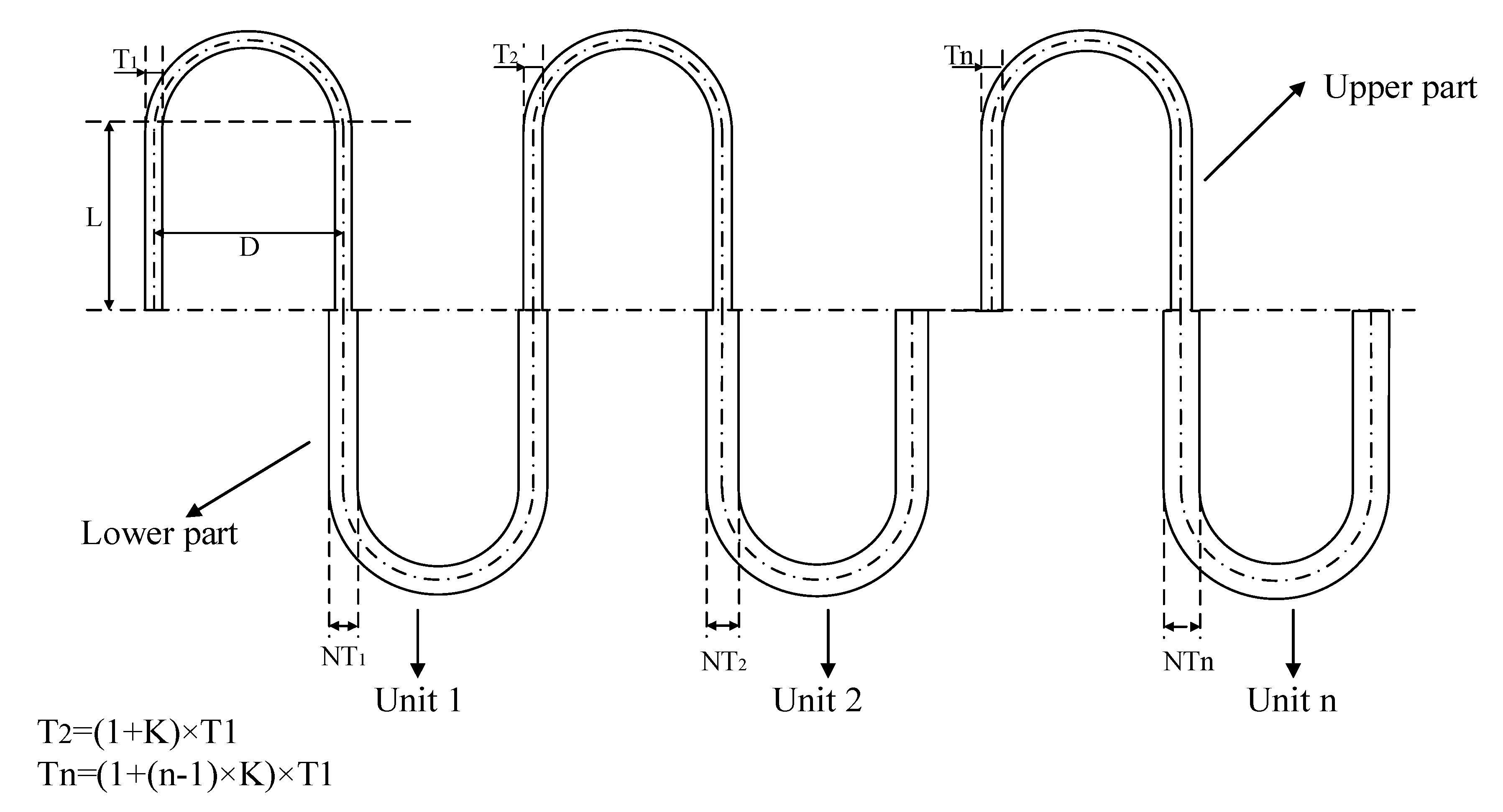
2.2. Asymmetric Stiffness Corrugated Panel

The corrugated panel is a kind of periodic structure, which can be described as a panel structure with repeating configurations. The stiffness of the structure in the corrugation axial direction is rather low, while being high in the perpendicular direction, exhibiting pronounced anisotropy. The equivalent model of the corrugated panel can predict the overall mechanical properties of the corrugated panel through a single corrugated panel unit and material characteristics. In the current study, an asymmetric stiffness corrugated panel is introduced, as shown in Figure 2. The stiffness change in the corrugated panel can be observed in two ways.
First, the thickness of the upper and lower parts within each corrugation unit has a thickness ratio N. Second, there is a linear variation K in the thickness between individual corrugation units. The single corrugated panel model based on asymmetric stiffness is set up through the two stiffness tailoring methods. In order to increase the folding angle of the corrugated structure, the actuator is stalled 10 mm below the central axis of the corrugated panel. When the actuator starts to provide the actuation force, it will impart a bending moment in the direction of folding, thereby facilitating the folding of the wingtip. According to the structure shown in Figure 2, a parametric model of the asymmetric stiffness corrugated panel is established to conduct a parameter analysis so that the effect of the two ways mentioned above on the folding angle of corrugated panels is verified.
In this paper, the main research aim is to verify the effect of the single-row corrugated panels based on the introduction of asymmetric stiffness to increase the folding angle without the flexible honeycomb structures in the leading and trailing edge. The corrugated panel prepared by 3D printing is only used to verify the conceptual design, and composite materials will be considered in the subsequent fabrication of the compliant structure.

3. Numerical Simulation

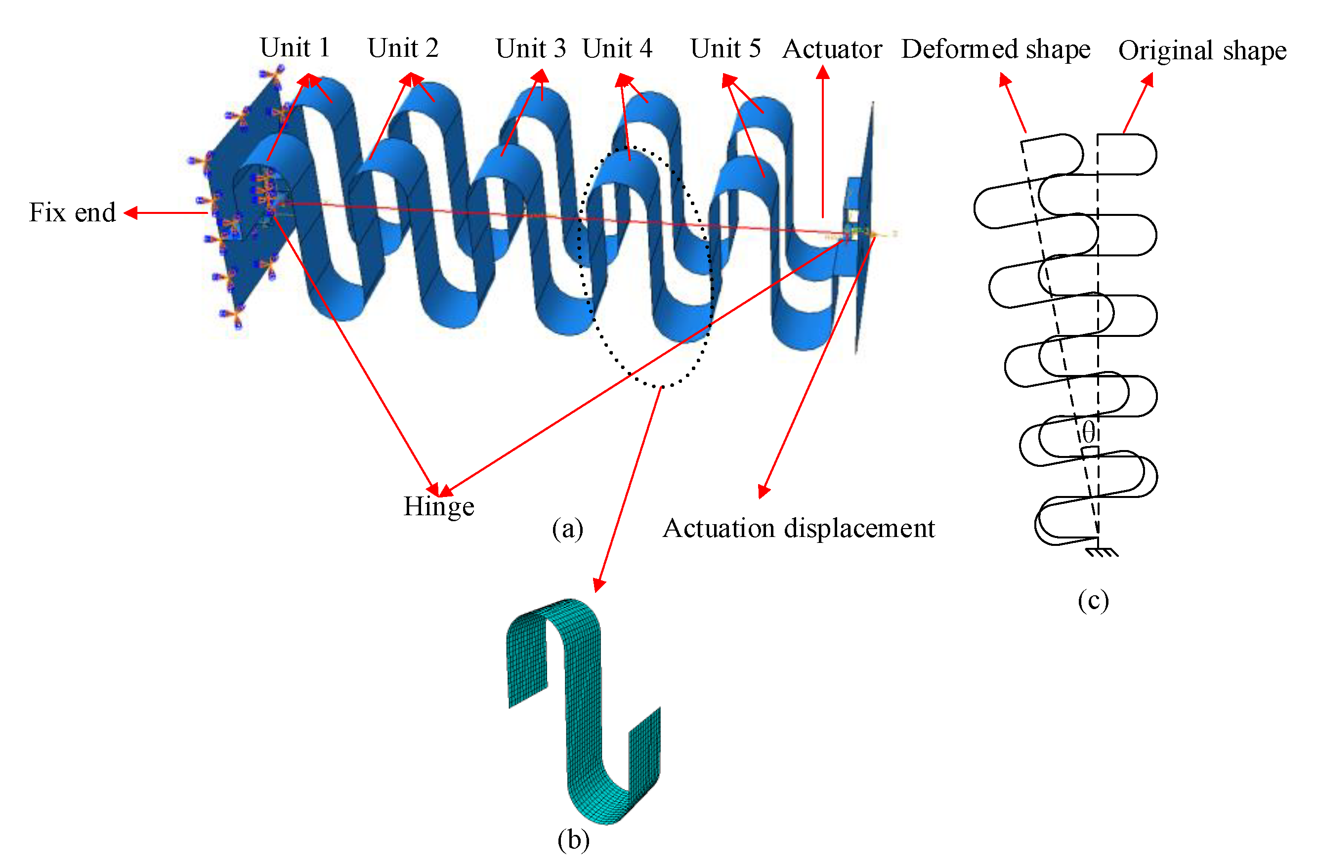
3.1. Structural Modelling

Considering the subsequent parameter analysis and structural optimisation of the corrugated panels, parametric modelling for corrugated panels is needed. Based on asymmetric stiffness, this paper established a parametric model of the corrugated panel structure by using commercial software Abaqus(2019)® and Python language(3.11.5). Parametric modelling of corrugated panels allows for rapid modification of structural parameters to achieve different layout configurations. For the corrugated panel structure, the parameters chosen for modelling include the vertical height L and the diameter D of each corrugated unit, the thickness T of the upper part of the first corrugation unit, the ratio N of the thickness between the upper and lower parts of the corrugation unit, and the ratio K of the thickness increment between the unit. For the finite element model of corrugated panels, the “S4 shell” unit is taken to simplify the corrugated panel under the premise of ensuring the computational accuracy, so as to reduce computational cost. The corrugated panels consist of five corrugated units, as shown in Figure 3. To ensure consistency in the subsequent parameter analysis, the total thickness of the structure is set at 80 mm. The middle section of 25 mm accommodates the linear actuator, with the actuator structure positioned 10 mm below the central axis of the corrugated panel. One end of the corrugated panel structure is fixed, and a linear actuator is constructed using a hinge and a translator, and actuation displacement is set as 30 mm. The folding angle, as shown in Figure 3c, is the angle between the connecting lines of the endpoints of the central axis before and after deformation. Both the simulations and subsequent experiments use PA as the material, with the specific material parameters detailed in Table 1.
Four different mesh sizes ranging from 1.5 to 3 mm are used to validate mesh independence, with specific results presented in Table 2. It can be seen that a decrease in mesh size has a small effect on the structural folding angle. Under the premise of ensuring accuracy and maintaining low computational cost, the mesh size is selected at 2.5 mm, resulting in a total of 8633 meshes for the structure.

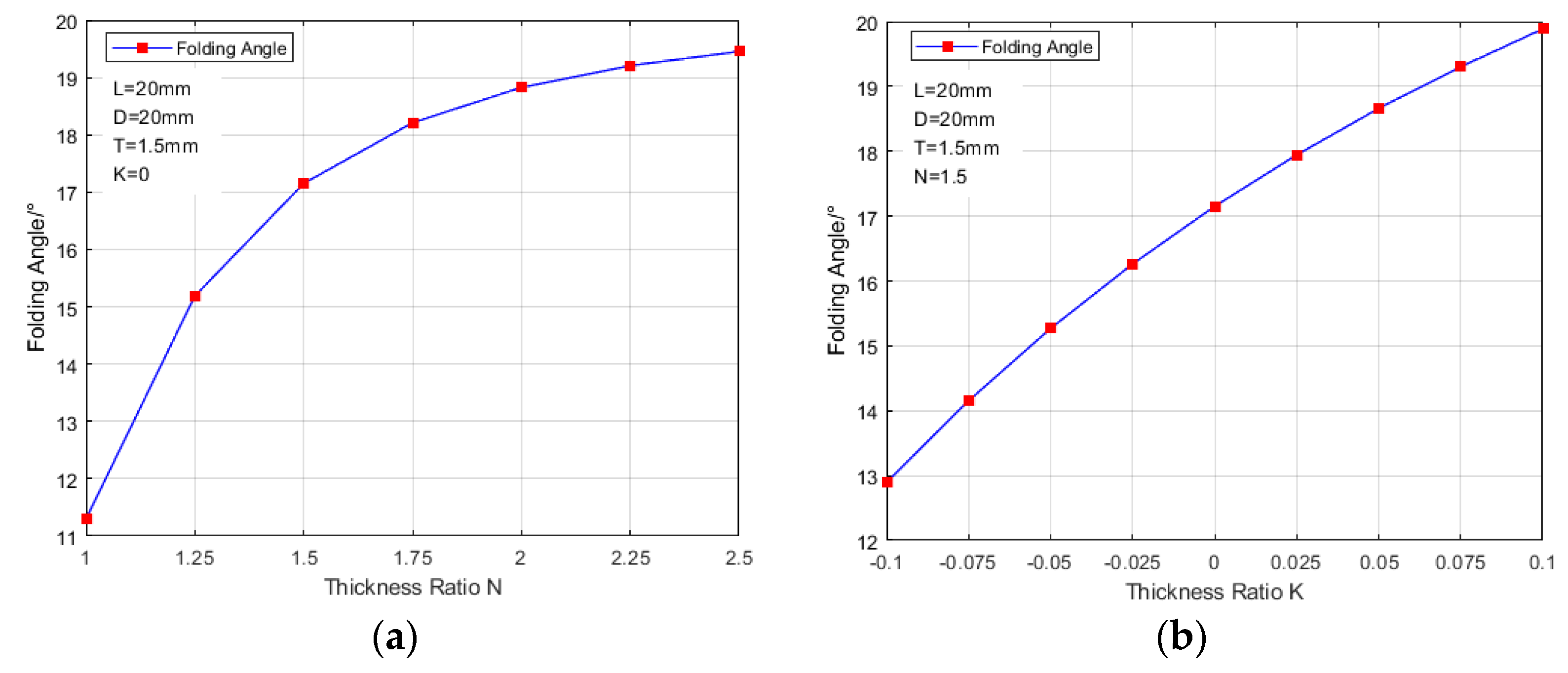
3.2. Parametric Study

In order to further explore the relationship between folding angle and asymmetric stiffness in the folding process of corrugated panel structure, parametric analysis is taken into consideration. We first studied the effect of stiffness tailoring on the shape-changing capability. Figure 4 shows the effect of parameter N and K on the folding angle of the corrugated panels. In order to meet the “shell” theory, the vertical length and diameter of each corrugated unit should be more than five times the maximum thickness of the structure. From the results shown in Figure 4a, it can be seen that when the thickness ratio of the upper and lower part is set as 1, the folding angle still exists. This is because the actuator is stalled 10 mm below the central axis of the corrugated panel. When the linear actuator is activated, it will provide an offset bending moment to the corrugated panel, which then, in turn, causes the structure to fold upwards. As the thickness ratio increases, the folding angle will grow because the increase in the thickness ratio enlarges the stiffness difference between the upper and lower part of the corrugation units. For single-row corrugated panels, the larger the thickness ratio is, the easier it is for the structure to fold. The simulation results demonstrate that modifying the stiffness of the upper and lower structures within a single corrugated unit could control the folding angle. Figure 4b examines how changes in the thickness between individual corrugated units affect the folding angle. It can be seen that decreasing the thickness of each unit reduces the folding angle, whereas increasing the thickness between corrugation units boosts the angle. This effect is because a larger thickness ratio between units increases the stiffness difference among them, thus aiding in wingtip folding. Conversely, a reduced thickness ratio lessens the stiffness difference, which in turn reduces the folding angle.
Figure 5 explores the effect of the thickness T of the upper part of the first corrugation unit on the folding angle. It can be seen that changing the thickness T does not have great effect on folding angle because changing the thickness T cannot change the stiffness difference between the upper and lower part of the corrugated panel. Therefore, it can be seen that the stiffness difference is the main factor, which increases the folding angle of the morphing wingtips.
The parameter analysis results show that adjusting the stiffness of each corrugated unit within a single-row corrugated panel can significantly increase the folding angle of the compliant wingtips. Carrying out further analysis to explore the optimal stiffness differences in compliant corrugated panels has the potential of improving the shape-changing capability of morphing wingtips.

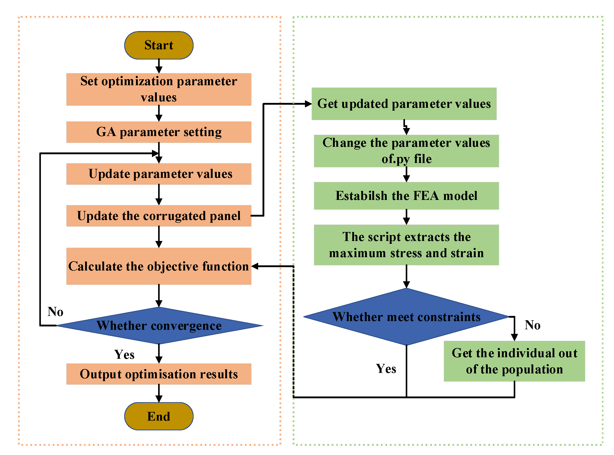
4. Optimisation and Analysis

According to the parametric study, it can be seen that adjusting the stiffness difference in the single-row corrugated panels has a great effect on the folding angle. The stiffness difference can be changed by tuning the parameters. To improve the folding performance of corrugated panels, the folding angle is taken as the objective:
G ( x ) = max   F o l d i n g   A n g l e
For the single-row corrugated panels, the parameters mentioned above are selected as optimisation parameters. In addition, the optimisation of corrugated panels needs to consider the maximum Von Mises stress and strain in the folding process, which is specifically expressed as the tensile and compressive stress generated. The stress and strain cannot exceed the allowable stress and strain. The safety factor is selected to be 2, that is, the maximum Von Mises stress generated in the corrugated panel folding process is less than 21 MPa. Based on the above parameter analysis results, the upper and lower limits of each parameter for subsequent optimisation are determined as shown in Table 3:
From the above three elements of optimisation, an optimised mathematical model of the corrugated panel structure, as shown in the following equation, is established:
G ( x ) = m a x   F o l d i n g   A n g l e s . t . S m i n < S _ a l l _ m a x S m a x E m i n < E _ a l l _ m a x E m a x x = L , D , T , N , K T
The variables need to satisfy the geometry constraints, which are
T × 1 + 4 × K < D / 5 T × 1 + 4 × K < L / 5
where m a x   F o l d i n g   A n g l e is the maximum structural folding angle of the corrugated panel, and L, D, T, N, K are the five independent parameters for the optimisation of the corrugated panel, which has been given the specific meaning above. S _ a l l _ m a x is the maximum Von Mises stress; S m i n and S m a x are the upper limit and lower limit of the Von Mises stress; E _ a l l _ m a x is the maximum structural strain; and E m i n and E m a x are the upper limit and lower limit of the structural strain.
In this paper, Abaqus® [22] software and MATLAB(R2020b)® [23] Genetic Algorithm are used to optimise the single-row corrugated panels. The specific optimisation process is shown in Figure 6. Python scripts are used to modify the finite element model and read the finite element analysis results, and the data flow is controlled through MATLAB for the optimisation. The maximum number of optimisation generations is 50, which is a stopping criterion for the optimisation process. The gene crossover probability is set as 0.8, which determines the proportion of individuals in the genetic algorithm that undergoes gene crossover in each generation. The population size is 50, and the function convergence percentage is 0.01% in the optimisation.
The optimisation results have been shown in Table 4. The parameters of the corrugated panel are plugged into the established parametric model for finite element analysis. Before the optimisation, the folding angle is 13.1 °. After the optimisation with asymmetrical stiffness introduced, the folding angle is 23.1°. A 76.3% increase can be obtained compared to the original design when other parameters remain unchanged, which shows that the stiffness tailoring can increase the folding angle significantly.

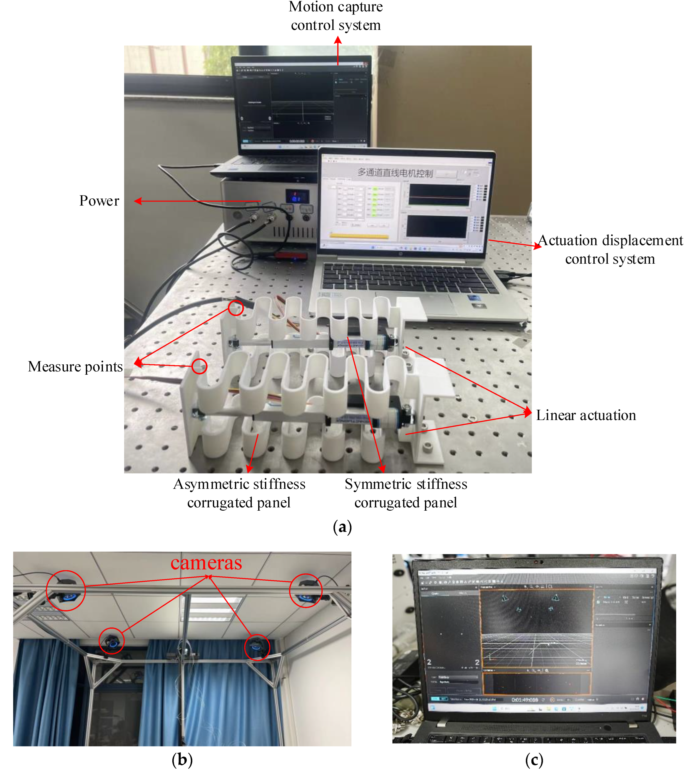
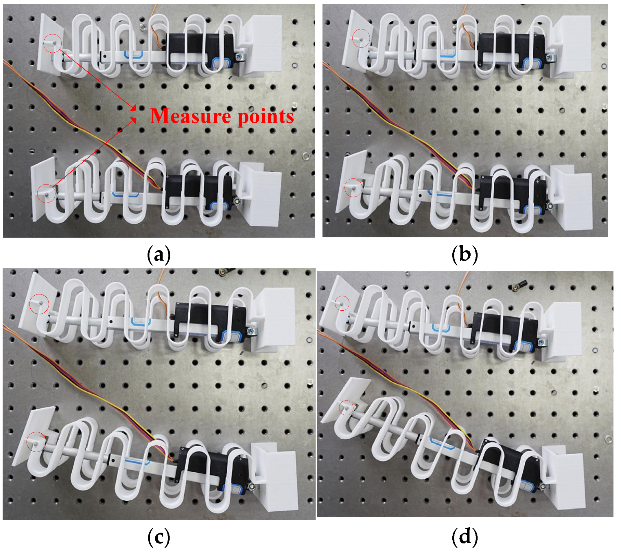
5. Experimental Validations

5.1. Experimental Design

In order to validate the effect of asymmetric stiffness on the shape-changing capability of corrugated panels, the corrugated panels of both symmetric stiffness and asymmetric stiffness are built on the basis of the optimised results mentioned above via 3D printing. The experimental platform is established, which is shown in Figure 7. The corrugated panel is fixed to the experimental platform at one end with bolts, aligning with the boundary conditions specified in the finite element analysis. A linear actuator is utilised to provide the actuation displacement. A motion capture device is used to capture the movement of the furthest left unit of the corrugated panel, and specific measure points are shown in Figure 7a. As Figure 7b shows, the motion capture device is composed of four cameras and a POE switch. Figure 7c shows the interface in which the operating system maps a three-dimensional point on a two-dimensional picture, thereby capturing the coordinate transformations during the folding process of the corrugated panel and retrieving the displacement changes in three directions. By further analysing these data, the folding angle of the two kinds of corrugated panel structures propelled by the actuator can be ascertained.

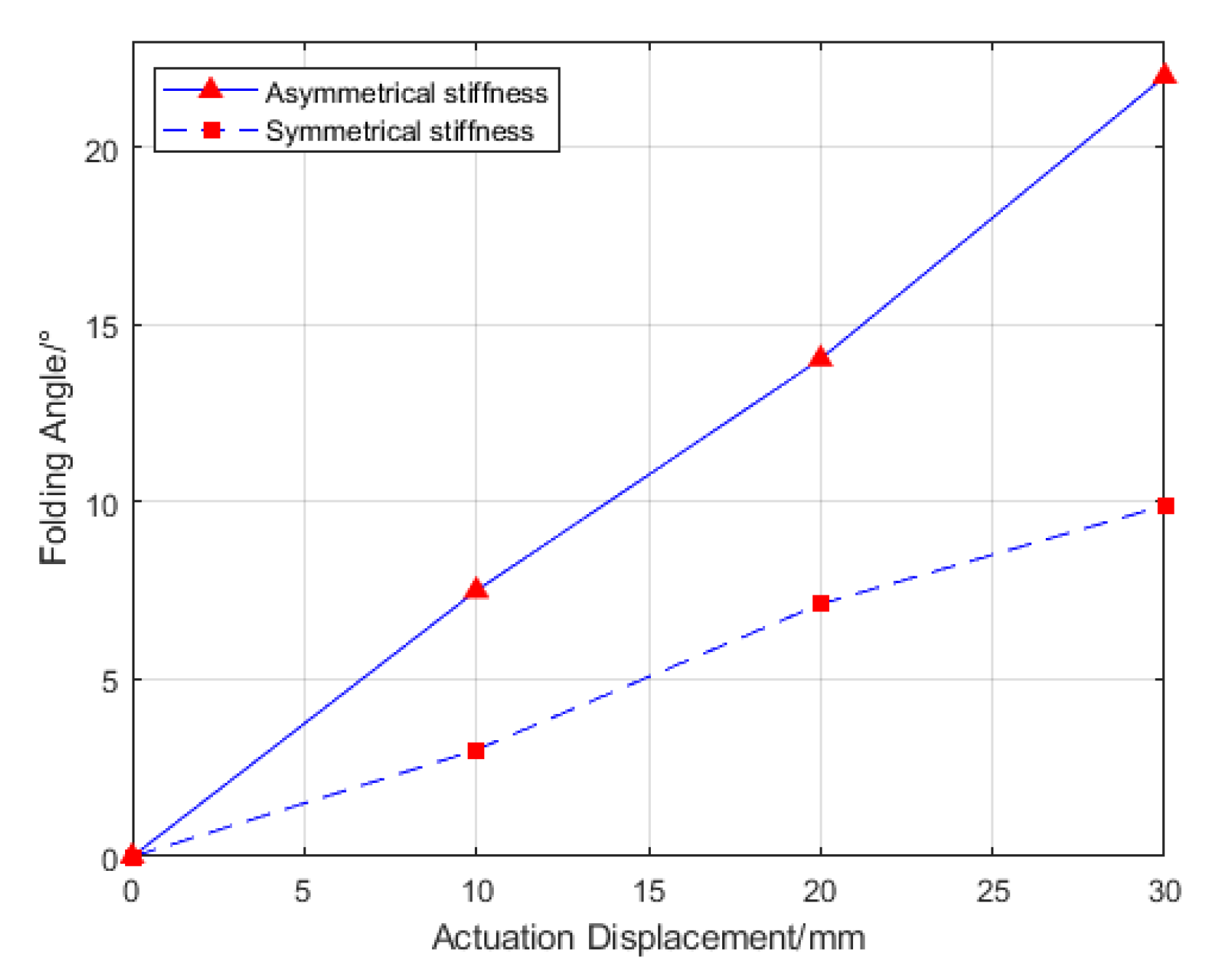
5.2. Experimental Analysis and Results

The corrugated panels with symmetric and asymmetric stiffness are installed on the experimental table and two actuators are used to actuate the corrugated panel structures separately. The Actuonix Motion Devices linear actuator P16-100-256-12-P is used, which is manufactured by Actuonix Company in Saanichton, Canada. The stroke of the actuator is 100 mm, and the maximum actuation can be as large as 300 N with the gear ratio 256:1. The actuator is controlled by its affiliated software and the extension of the actuator is given as a feedback signal. In order to further explore the folding angle in the different actuation displacement, the displacements for the corrugated panel structures are set as 10 mm, 20 mm, and 30 mm. The specific folding angles are shown in Figure 8 and Figure 9.
Table 5 summarises the experimental results and numerical results. Some errors remain between the experimental results and the simulation results, which could be mainly caused by the differences in the material properties used in the numerical simulation. However, both simulation and experimental results show that the introduction of asymmetric stiffness can increase the folding angle of the corrugated panel.
The experimental results show that before the optimisation, the folding angle is 9.9° when the actuation displacement is set as 30 mm. After the optimisation, the folding angle becomes 22.1°. The increase in the folding angle is divided by that of the symmetric stiffness corrugated panel, which leads to the increment of 123.2%, and verifies that the asymmetric stiffness could increase the folding angle significantly.

6. Conclusions

This paper validated the feasibility of introducing asymmetric stiffness to the compliant folding wingtip using the single-row corrugated panels on increasing the folding angle. The following conclusions can be made:
  • By establishing a parametric model of single-row corrugated panels and carrying out a parametric analysis, the effects of stiffness tailoring on changing the folding angle of corrugated panels have been validated. The results show that the folding angle of the corrugated panel could be effectively increased by tuning the thickness characteristics of the corrugated panel.
  • A framework is created to optimise the corrugated panels using a genetic algorithm. The results show that the folding angle of the corrugated panel structure could be effectively increased while the maximum Von Mises stress and strain can satisfy the constraints.
  • Based on the optimisation results, corrugated panels of symmetric and asymmetric stiffness are fabricated using 3D printing and validated with experiment. The experimental results indicate that the folding angle of the asymmetric stiffness corrugated panel structure is increased by 123.2% compared with symmetric stiffness, demonstrating its potential for the design of compliant morphing wingtip structures.
In future research, the equivalent model of asymmetric stiffness can be derived to further explore the effects and mechanisms of asymmetric stiffness. Additionally, the focus of this study was to explore the feasibility of two stiffness tailoring methods in enhancing the folding angle performance of the corrugated panel structure without considering the capability to carry aerodynamic loads, and the entire wingtip structure can be established for the simulation analysis and experimental work.

Author Contributions

Conceptualization, Z.H., S.F. and C.W.; methodology, Z.H., C.W. and S.F.; software, Z.H. and S.F.; validation, X.S. and J.Z.; formal analysis, Z.H.; investigation, LI Songqi and Z.H.; resources, C.W. and X.S.; data curation, Y.Z. and S.L.; writing—original draft preparation, Z.H.; writing—review and editing, C.W.; visualisation, Y.Z. and S.L.; supervision, C.W., X.S. and J.Z.; project administration, Z.H.; funding acquisition, C.W. and X.S. All authors have read and agreed to the published version of the manuscript.

Funding

This research was supported by the National Natural Science Foundation of China (Grant No. 52305262), the Fundamental Research Funds for the Central Universities (No. NT2024001), the State Key Laboratory of Aerodynamics (Grant No. RAL202303-1), Beijing Municipal Natural Science Foundation (Grant No.1232014), and the Starting Grant of Nanjing University of Aeronautics and Astronautics.

Data Availability Statement

The data presented in this study are available on request from the corresponding author. The data are not publicly available due to privacy.

Conflicts of Interest

The authors declare no conflicts of interest.

References

  1. Weisshaar, T.A. Morphing aircraft technology-new shapes for aircraft design. In Multifunctional Structures/Integration of Sensors and Antennas, Meeting Proceedings RTO-MP-AVT-141, Overview 1; RTO: Neuilly-sur-Seine, France, 2006. [Google Scholar]
  2. Li, D.; Zhao, S.; Da Ronch, A.; Xiang, J.; Drofelnik, J.; Li, Y.; Zhang, L.; Wu, Y.; Kintscher, M.; Monner, H.P.; et al. A review of modelling and analysis of morphing wings. Prog. Aerosp. Sci. 2018, 100, 46–62. [Google Scholar] [CrossRef]
  3. Smith, D.D.; Lowenberg, M.H.; Jones, D.P.; Friswell, M.I. Computational and experimental validation of the active morphing wing. J. Aircr. 2014, 51, 925–937. [Google Scholar] [CrossRef]
  4. De Breuker, R.; Werter, N. On the importance of morphing deformation scheduling for actuation force and energy. Aerospace 2016, 3, 41. [Google Scholar] [CrossRef]
  5. Montano, F.; Dimino, I.; Milazzo, A. A Preliminary Evaluation of Morphing Horizontal Tail Design for UAVs. Aerospace 2024, 11, 266. [Google Scholar] [CrossRef]
  6. Bourdin, P.; Gatto, A.; Friswell, M.I. Aircraft control via variable cant-angle winglets. J. Aircr. 2008, 45, 414–423. [Google Scholar] [CrossRef]
  7. Han, M.W.; Rodrigue, H.; Kim, H.; Song, S.H.; Ahn, S.H. Shape memory alloy/glass fiber woven composite for soft morphing winglets of unmanned aerial vehicles. Compos. Struct. 2016, 140 (Suppl. C), 202–212. [Google Scholar] [CrossRef]
  8. Li, W.; Xiong, K.; Chen, H.; Zhang, X. Research on variable cant angle winglets with shape memory alloy spring actuators. Acta Aeronaut. Et Astronaut. Sin. 2012, 33, 22–33. [Google Scholar]
  9. Spivey, D.; Sur, P. Spanwise adaptive wing. In NASA Report: AFRC-E-DAA_TN57916; AIAA Aviation: Atlanta, GA, USA, 2018. [Google Scholar]
  10. Chen, Y.; Yin, W.; Liu, Y.; Leng, J. Structural design and analysis of morphing skin embedded with pneumatic muscle fibers. Smart Mater. Struct. 2011, 20, 085033. [Google Scholar] [CrossRef]
  11. Sun, J.; Gao, H.; Scarpa, F.; Lira, C.; Liu, Y.; Leng, J. Active inflatable auxetic honeycomb structural concept for morphing wingtips. Smart Mater. Struct. 2014, 23, 125023. [Google Scholar] [CrossRef]
  12. Sun, J.; Du, L.; Scarpa, F.; Liu, Y.; Leng, J. Morphing wingtip structure based on active inflatable honeycomb and shape memory polymer composite skin: A conceptual work. Aerosp. Sci. Technol. 2021, 111, 106541. [Google Scholar] [CrossRef]
  13. Yin, W.; Shi, Q. Review of Material and Structure for Morphing Aircraft Skin. Aeronaut. Manuf. Technol. 2017, 17, 24–29. [Google Scholar]
  14. Thill, C.; Etches, J.A.; Bond, I.P.; Potter, K.D.; Weaver, P.M. Composite corrugated structures for morphing wing skin applications. Smart Mater. Struct. 2010, 19, 124009–124018. [Google Scholar] [CrossRef]
  15. Dayyani, I.; Khodaparast, H.H.; Woods, B.K.S.; Friswell, M.I. The design of a coated composite corrugated skin for the camber morphing airfoil. J. Intell. Mater. Syst. Struct. 2014, 26, 1592–1608. [Google Scholar] [CrossRef]
  16. Bai, J.; Chen, D.; Xiong, J.; Dong, C. A semi-analytical model for predicting nonlinear tensile behaviour of corrugated flexible composite skin. Compos. Part B Eng. 2019, 168, 312–319. [Google Scholar] [CrossRef]
  17. Zhang, J.; Wang, C.; Shaw, A.D.; Amoozgar, M.R.; Friswell, M.I. Passive energy balancing design for a linear actuated morphing wingtip structure. Aerosp. Sci. Technol. 2020, 107, 106279. [Google Scholar] [CrossRef]
  18. Zhang, J.; Shaw, A.D.; Wang, C.; Gu, H.; Amoozgar, M.R.; Friswell, M.I.; Woods, B.K.S. Aeroelastic Model and Analysis of an Active Camber Morphing Wing. Aerosp. Sci. Technol. 2021, 111, 106534. [Google Scholar] [CrossRef]
  19. Wang, C.; Khodaparast, H.H.; Friswell, M.I. Conceptual study of a morphing winglet based on unsymmetrical stiffness. Aerosp. Sci. Technol. 2016, 58, 546–558. [Google Scholar] [CrossRef]
  20. Wang, C.; Khodaparast, H.H.; Friswell, M.I. Development of a morphing wingtip based on compliant structures. J. Intell. Mater. Syst. Struct. 2018, 29, 3293–3304. [Google Scholar] [CrossRef]
  21. Wang, C.; Khodaparast, H.; Friswell, M.; Shaw, A. Compliant structures based on stiffness asymmetry. Aeronaut. J. 2018, 122, 442–461. [Google Scholar] [CrossRef]
  22. Dassault, S. Abaqus Analysis User’s Guide; Dassault Systèmes: Vélizy-Villacoublay, France, 2019. [Google Scholar]
  23. The MathWorks Inc. MATLAB R2020b; The MathWorks Inc.: Natick, MA, USA, 2020. [Google Scholar]
Figure 1. (a) Compliant morphing wing, (b) folding deformation diagram.
Aerospace 11 00682 g001
Figure 2. Asymmetric stiffness corrugated panel.
Aerospace 11 00682 g002
Figure 3. (a) FEM model, (b) meshes in corrugated panel, (c) folding deformation diagram.
Aerospace 11 00682 g003
Figure 4. The effect of stiffness tailoring on the folding angle. (a) The effect of the upper and lower thickness ratio N on the folding angle. (b) The effect of the corrugated unit thickness increment ratio K on the folding angle.
Aerospace 11 00682 g004
Figure 5. Effect of corrugated panel thickness on folding angle.
Aerospace 11 00682 g005
Figure 6. Optimisation flow chart.
Aerospace 11 00682 g006
Figure 7. Establishment of experiment platform. (a) Experiment platform, (b) motion capture device, (c) operation interface.
Aerospace 11 00682 g007
Figure 8. Folding angle diagram of corrugated panel. (a) Actuation displacement 0 mm. (b) Actuation displacement 10 mm. (c) Actuation displacement 20 mm. (d) Actuation displacement 30 mm.
Aerospace 11 00682 g008
Figure 9. Folding angle diagram of two kinds of corrugated panel actuation displacement.
Aerospace 11 00682 g009
Table 1. Properties parameters of PA.
Modulus/MPaPoisson’s RatioYield Strength/ MPaDensity/ton/mm3
15000.3420.93 × 10−9
Table 2. Mesh independence validation.
Mesh size/mm1.522.53
Folding angle/°11.2411.2711.2911.34
Table 3. Upper and lower limits of design parameters.
ParameterLower ValueUpper Value
LVertical length15 mm35 mm
DDiameter of each corrugation unit15 mm35 mm
TUpper thickness of the first corrugation unit1.5 mm2.5 mm
NUpper and lower thickness ratio13
KThe ratio of thickness increment between corrugation units−0.10.1
Table 4. Optimisation results of design parameters.
ParameterOptimal Value
Vertical length17.91 mm
Diameter of each corrugation unit18.08 mm
Upper thickness of the first corrugation unit1.51 mm
Upper and lower thickness ratio1.73
The ratio of thickness increment between corrugation units0.092
Folding angle before optimisation13.1°
Folding angle after optimisation23.1°
Table 5. The comparison of numerical results and experimental results.
Numerical ResultsExperimental Results
Before Optimisation13.19.9
After Optimisation23.122.1
Increment76.1%123.2%
Disclaimer/Publisher’s Note: The statements, opinions and data contained in all publications are solely those of the individual author(s) and contributor(s) and not of MDPI and/or the editor(s). MDPI and/or the editor(s) disclaim responsibility for any injury to people or property resulting from any ideas, methods, instructions or products referred to in the content.

