Review

A Brief Review of the Actuation Systems of the Morphing Systems in Wind Tunnel Models and a Case Study

1
AVIC Aerodynamics Research Institute, Shenyang 110034, China
2
Aviation Key Laboratory of Science and Technology of High Speed and High Reynolds, Shenyang 110034, China
*
Author to whom correspondence should be addressed.
Aerospace 2024, 11(8), 666; https://doi.org/10.3390/aerospace11080666
Submission received: 29 June 2024 / Revised: 2 August 2024 / Accepted: 2 August 2024 / Published: 13 August 2024
(This article belongs to the Special Issue Structures, Actuation and Control of Morphing Systems)

Abstract

:
Typical wind tunnel testing involves a series of configuration changes (to the angles of control surfaces) to simulate the lift and resistance characteristics of control surfaces in different flight conditions. It is very time-consuming and labor-intensive to manually change the angles of control surfaces, especially in the large continuous reflux wind tunnel. Thus, there is a demand for a morphing system design within the wind tunnel model that can deflect the control surfaces remotely and automatically. The basic design flow and characteristics of different actuator techniques for the morphing systems were summarized in this paper, including electromechanical actuator, pneumatic actuator, shape memory material actuator and piezoelectric actuator. In the case study, the accuracy of the control surface angle and aerodynamic performance of the ultrasonic-driven automatic control surface system reached the level of traditional fixed control surface systems, while its efficiency was much higher than that of the traditional fixed control surface systems.

1. Introduction

The development of aircraft has a history of more than 100 years. With the rapid development of various technologies, various flight requirements have been put forward, and the flight environment that the aircraft needs to adapt to is more complex. In this regard, researchers are constantly proposing various new concept aircraft. The process of these aircraft from concept to product also requires pre-research, design, verification and other processes [1]. Wind tunnel testing utilizes a scaled-down model of the aircraft, which not only reduces the early production and manufacturing costs, but also verifies the gap between the numerical calculation results and the actual results, thereby optimizing the computational methods [2].
Typical wind tunnel tests involve a series of configuration changes aimed at assessing the effectiveness of control surfaces such as elevators, flaps, and other control elements at various positions. These experiments are usually applied to comprehensively characterize the stability and control performance of the test aircraft. However, in the early stages, wind tunnel tests tested the lift and resistance characteristics by manually changing the angle of the control surface (shown in Figure 1), which was less efficient [3].
In a large continuous wind tunnel, the change of each rudder status goes through six main stages, including slowing down the compressor, depressurizing the wind tunnel, opening the wind tunnel door, changing the rudders manually, speeding up the compressor and closing the door. In a practical test, it takes about 2 hours to change the rudder surface status according to the above procedures. Therefore, for some conventional aerodynamic characteristics tests of aircrafts, these tests of various angles of rudder deflection mean a huge cost. By contrast, for an automatic morphing system, the process takes only about one minute, including giving the commands and driving the rudder to deflect. Consequently, with the increasing demand for aerodynamic characteristics evaluation of aircraft, the demand for remote and continuous control technology for wind tunnel models is increasing [4].
With the development and maturity of automatic control systems, remote automatic control technology for wind tunnel model control surface deflection has greatly improved the testing efficiency of wind tunnel tests and reduced labor costs. However, it remains challenging to install a control surface actuation mechanism within the limited space such as a scale model of an aircraft.
In recent years, the rapid development of morphing aircraft has influenced the development of the wind tunnel test techniques in two significant ways: firstly, the development of morphing aircraft leads to more test requirements of novel designs, making the automatic and remote deflection of the control surfaces even more demanding; secondly, the development of the morphing techniques has also helped to make the remote and automatic control surfaces in the wind tunnel models possible.
Smart materials and structural technology have developed rapidly in the past few decades, which has also led to revolutionary changes in the actuate technology of morphing aircraft [5]. Smart materials, such as shape memory alloys and piezoelectric materials, can deform with changes in external temperature and voltage, thereby generating the driving force. The more lightweight and integrated actuate components composed of these smart materials can effectively replace traditional actuate forms (such as manual, hydraulic, etc.), effectively reducing the complexity of the actuate system, and improving reliability and space utilization [6]. Furthermore, the driving system of smart materials not only has the ability to withstand certain loads, but also makes it possible to implement a remote continuous control system for wind tunnel models.
To this end, this paper summarizes the actuation techniques of the morphing wing in several different wind tunnel tests and the effects of using smart material and structure on aerodynamic performance.

2. Definitions, Components and Requirements of the Morphing Systems for Wind Tunnel Models

2.1. Definition of Wind Tunnel Test Model

The wind tunnel test model is a scaled model designed and produced based on the similarity theory, which is used to simulate the aerodynamic characteristics of the aircraft in different flight states, so as to comprehensively evaluate the performance of the aircraft. The automatic control surface model in the wind tunnel test mainly includes the model body, drive system, transmission system and sensing system, which can remotely control the control surface rotation. Compared to the traditional manual change the angle, the automatic control surface model is more efficient and energy-saving.

2.2. Components of the Wind Tunnel Model

The wind tunnel test model of the automatic control surface is shown above in Figure 2 and typically consists of several key parts:
(a)
Model body: This is the main structure of the wind tunnel test model, designed to evaluate the overall aerodynamic shape and aerodynamic characteristics. For the morphing wing, the main structure includes the external profile of the wing and the internal support structure. The model body is also the installation platform of the drive system, the transmission system and the sensor system. Additionally, ensuring the basic strength and stiffness requirements, the critical areas for reducing the aircraft’s weight are identified.
(b)
Drive system: This provides power to the morphing wing model and usually includes the motor, hydraulic cylinder, shape memory alloy, piezoelectric material or other smart material actuator. Under the action of the control signal, the actuation system drives the control surface to rotate to remotely change the rotation angle.
(c)
Transmission system: The role of the transmission system is to achieve the motion conversion and power transmission, usually by some connecting rod mechanism, lead screw nut and worm gear. For linear actuators such as hydraulic cylinders, shape memory alloy wires and piezoelectric pumps, it is usually necessary to convert the linear motion into rotation to obtain the angle of rotation. For rotary motors and ultrasonic motors, due to space constraints, it is necessary to design a transmission system to transmit power to the control surface.
(d)
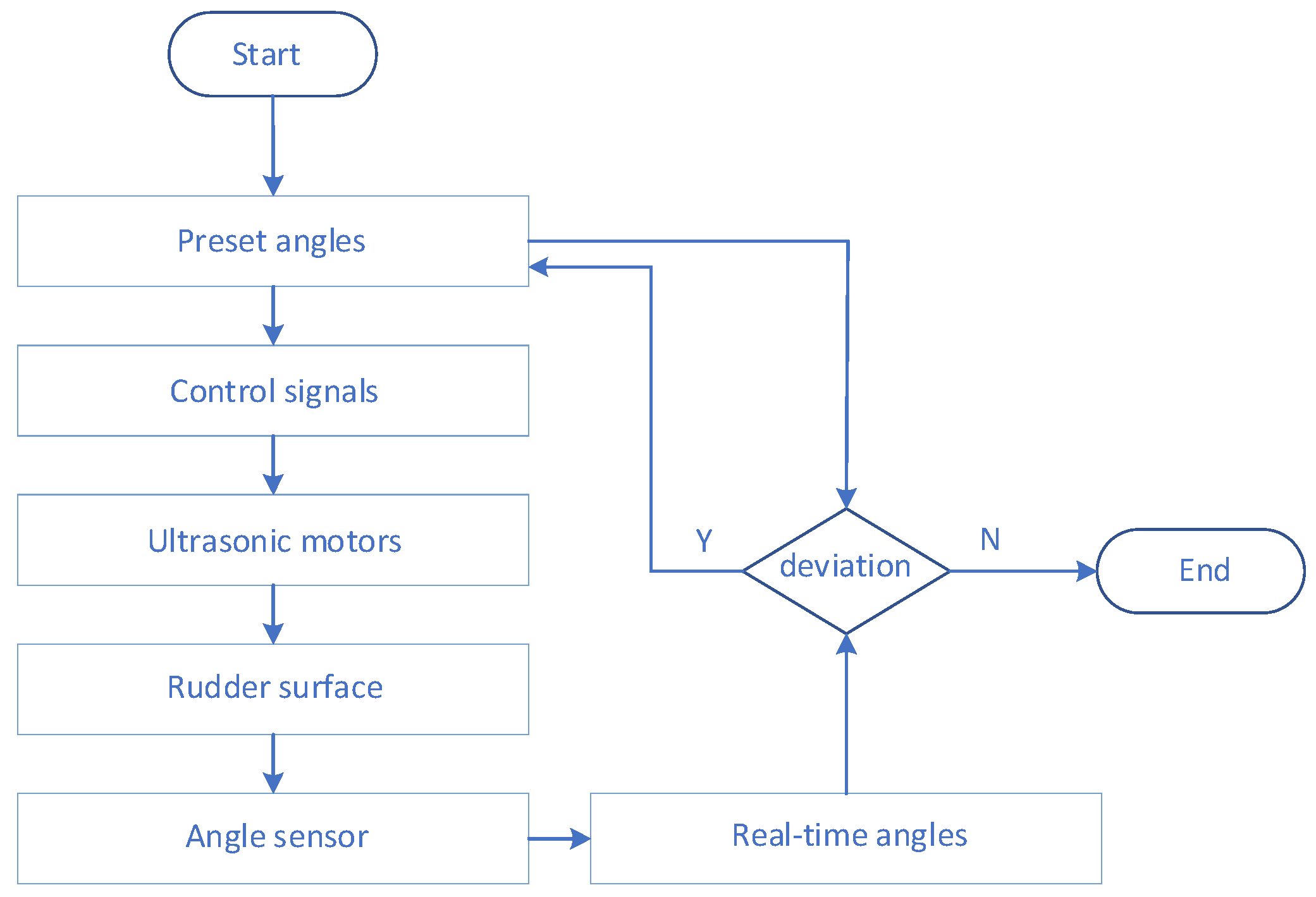
Sensing system: This can monitor the rotation angle of the control surface in real time to achieve accurate feedback control. Angle encoders are usually used to measure the rotation angle of the control surface shafts. For automatic control surface control systems, the closer the angle sensor is installed to the control surface shaft, the higher the angle control accuracy. In the actual model design process, the installation position of the angle sensors often needs to be balanced among the various test requirements, structural space requirements and strength requirements of the structure.

2.3. Requirements of the Wind Tunnel Test Model

Different actuation techniques have distinct performance characteristics, so in practical applications, the most suitable actuator should be selected according to the specific wind tunnel test requirements, internal space and motion characteristics. In general, the pneumatic actuators are suitable for the test of large deflection and fast response, the electromechanical actuators are suitable for the test of high accuracy and high stability, the shape memory materials are suitable for the situation that requires a fast response and adaptive shape control, and the piezoelectric materials are suitable for the dynamic test of lightweight and miniaturization. The most suitable actuation techniques should be selected according to the requirements of the wind tunnel test and model structure design.
In the automatic control surface model, the requirements for the drive system mainly include the following aspects:
(a)
Adequate drive stroke: The drive system needs to drive the control surface to achieve various rotation angles for the control surface effect tests, which means that the model drive system needs to provide enough drive stroke. The drive stroke indicator is the primary requirement for selecting and designing drive and transmission schemes.
(b)
Adequate driving force: Since the model will be subjected to large wind loads in wind tunnel tests, especially under conditions of large control surface angles, the drive system needs to have sufficient driving force. The actuators with high power and high energy density are the necessary condition to complete the test of high Mach number and large control surface angle.
(c)
Fitting into limited space: The wind tunnel test model is a smaller model compared to the real aircraft based on the similarity principle. The internal space is very precious, so the actuators should be miniaturized as far as possible under the premise of satisfying the driving stroke and driving force, so as to be integrated into the complex model system.
(d)
High accuracy: Conventional wind tunnel force measurement and pressure measurement tests have very high accuracy requirements, and small rotation errors of the control surface could bring large test errors, so the control accuracy of the drive system is highly required.
In addition to meeting the above requirements, it may be necessary for the drive system to meet the negative pressure and temperature environment of the wind tunnel. However, most actuators, whether traditional actuators or actuators made of smart materials, struggle to perfectly meet the above requirements. In the actual design of the automatic control surface model, the priority of these indicators is often listed according to the test requirements, and the best choice can be made after weighing the aerodynamic test requirements and the model design requirements.

3. Classifications of the Actuation

We will conduct a brief overview of the several wind tunnel test model actuator technologies involved in this paper: pneumatic, electromechanical, shape memory material and piezoelectric material actuation technology. The above actuation methods are all key components in driving the deflection of rudders in the wind tunnel test model. The purpose of this paper is to discuss the application methods and scenarios of these actuation technologies and their potential in the optimization design of wind tunnel test models.
The four actuation methods mentioned above are currently common methods for continuously controlling panel deflection in wind tunnel tests in different application scenarios. They can all achieve remote, automated and intelligent control. Through in-depth analysis of the characteristics of these actuation methods, the most suitable choice for a specific scenario can be better determined in the future, thereby improving the efficiency and accuracy of wind tunnel testing.

3.1. Electromechanical Actuators

As a mature actuation technology, electromechanical actuators provide high-precision control and help simulate various flight scenarios. In this paper, we will take an in-depth look at the key role of electromechanical actuators in wind tunnel testing models, including their working principles, performance characteristics and latest application trends, to better understand how this technology can be used to advance the development of wind tunnel testing.
Nguyen et al. conducted a recent real-time adaptive resistance reduction wind tunnel test using a highly flexible wing model equipped with Variable Camber Continuous Trailing Flap (VCCTEF) technology [7]. Using linear actuators, the crank shaft converted the linear motion into the rotation of the wing tip. The 12 control surfaces of a sub-scale model were driven by 12 independent servo units, six of which were arranged on the inboard wing, with the other six on the outboard wing, which achieved a wing tip deflection of 10% of the wing semi-span. Due to mechanical backlash and manufacturing errors in the transmission chain, the accuracy of the flap position actually only reached 1 degree. The use of pseudo-inverse optimization produced up to a 36 count or 9.4% drag reduction for the off-design lift coefficient of 0.7. Federico was involved in the design, manufacturing and testing phases [8,9]. In Pecora’s program [8], the rotation of the worm gears was transmitted to the tangentially of each worm gear. An eccentric pushing link was installed on each worm gear to obtain a linear motion. In the end, the translation motion was transferred into a rotation of a control surface by a hinge line. The safety requirements and effective convenience for large civil aircraft wind tunnel test were crucial in a multi-modal camber morphing flap model of the CleanSky program. In Arena’s program [9], the mechanism was driven by a servo actuator that realized a target deflection range of −5 to 5 degrees on a 5.5 m full-scale morphing wing trailing edge. The transmission chain consisted of an aluminum linear rail, a gliding element, a crank and a steel connection beam. Several FE analysis cases were investigated by MSC Nastran to estimate stiffness and inertial, which verified the absence of the flutter criticalities up to 1.15 VD in nominal conditions and VD in the case of a single failure. In the research by Vasista [10], a demonstrator morphing leading edge was designed and manufactured as an intermediate step in preparation for the wind tunnel testing of a droop-nose adaptive morphing wingtip as part of the European FP7 project NOVEMOR. This demonstrator featured a flexible fiberglass skin and a monolithic aluminum internal compliant support structure generated by topology optimization. The compliant region was driven by a linear stepper motor actuator.
Liang [11] designed a small electric steering system for the wind tunnel testing of aircraft aileron models. Based on the structural analysis of a space orthogonal link mechanism combined with a screw-nut system and links, a kinematic parametric mathematical model was established using ADAMS software. After the optimization of structural parameters, the rotation angle of a control surface reached almost 70 degrees, and the average angular velocity was 2.331 degrees per second. In the study conducted by Dong [12], an automatic variable-angle system for a buried motivator was developed to address the variable angle requirements of wind tunnel test models. The motor drove the ball screw to obtain linear motion, and the spatial CAM converts the horizontal linear motion into the rotation of the control surface. It was with this transmission system design idea that the deformation system could be arranged within a height of only 25 mm and obtained a high control accuracy.
Figure 3 depicted the electromechanical actuator developed by Federico. The actuator’s shaft rotation speed was reduced by an integrated planetary gearhead and transferred to a set of worm gears coaxial with the actuator shaft (stage 1, Figure 3b). The rotation of the worm gears was transmitted to gear wheels installed tangentially to each worm gear (stage 2, Figure 3b). An eccentric pushing link was mounted on the top of each gear wheel and was connected to the movable segment/tab. Two spherical hinges were used to connect the link with the gear wheel and with the movable segment/tab. The rotation of the gear wheel was converted into the translation of the pushing link along the chord of the flap (stage 3, Figure 3b), which, in turn, enabled the rotation of the segment/tabs by inducing torque around their hinge line. Each flap robotic (finger-like) rib consisted of two actuation transmission stages, providing each flap rib with two rotational degrees of freedom around its hinge line.

3.2. Pneumatic Actuators

Pneumatic Artificial Muscles (PAMs) are made of flexible materials. By designing the elastic coefficient of materials in one or several directions, the flexible body is inflated or discharged to generate the corresponding force. This kind of actuator can generate enough driving force and driving stroke, and can be designed according to the actual actuating demand, with certain lightness and flexibility.
Woods [13] developed and tested a new aircraft trailing edge actuator system based on a PAM actuator. The wind tunnel experiments showed that M = 0.13 wind speed conditions, and the trailing edge deflected the flap ±20° for actuation frequencies up to 24 Hz. Peel [14] applied PAM as the actuating element of the structural variant in the variant wing. During the contraction and relaxation of the actuator, the leading edge and trailing edge of the flexible composite wing skin were deformed, so as to obtain the best aerodynamic shape and improve flight efficiency. In the research, a series of developments and iterations of the pneumatic actuator were carried out, starting with the initial braided pneumatic actuator that had sufficient power and no leakage, but also had the function of gradient action.
Zhou [15] proposed an intelligent structure with distributed pneumatic actuators to replace part of the traditional wing, so that the curvature of the wing could produce adaptive changes, thus adapting to the current flight environment. They designed, built and tested a wind tunnel test model with six pneumatic actuators, including four controllable shape-changing degrees of freedom and two internal load paths that provide pre-stress. The results showed that under various aerodynamic loads, the aerodynamic performance of the variant wing based on aerodynamic motion could achieve accurate shape control. In the study conducted by Yin [16], the relationship between the static output force and the air pressure of PAMs was designed to measure, and the relationship between the output force and the contraction ratio was obtained. Based on the above relationship, a variable camber wing based on PAM was developed in the wind tunnel test model. The test results showed that compared with the base airfoil, the test model with flexible trailing edge had an obvious lift increase effect at each angle of attack, and the analysis results were in good agreement.
In Woods’s [13] study, PAMs were used as drivers for trailing edge flaps and were validated in wind tunnel tests. As shown in Figure 4, two PAMs were arranged on the wing, one above and the other below the shaft. The wing shaft was supported by ball bearings. By controlling the expansion and contraction of the upper and lower PAMs, a pure rotational moment about the flap spar was obtained. For better actuation, a turnbuckle was placed in the middle to adjust the tensile pre-strain. The wind tunnel test results showed that PAMs with an active length of 8 cm and an outer diameter of 1.27 cm could produce a blocked force of 110 N at an operating pressure of 0.62 MPa.

3.3. Shape Memory Material Actuator

Utilizing the shape memory effect of the shape memory alloy, the actuator transforms heat energy into either displacement or force output. Typically, shape memory alloy actuators exist in the form of wires, plates, springs, rods, tubes or other structural forms, and need to be combined with specific application scenarios to determine if they are easy to assemble, if they can be more effectively integrated with the base material and the difficulty of environmental settings, among other factors, to determine the appropriate structural form. The recent research status of SMA actuators will now be introduced. This can be briefly summarized into three stages: empirical design, simple one-dimensional design, and complex three-dimensional design.
The Smart Wing program [17] integrated shape memory alloy twist tubes into the drive system of the deformed wing for hingeless and smooth twist control of the wing’s rear edge. Flexible front and rear edges driven by shape memory alloy wires were used. Two 16% reduction models, a conventional model and a model using the shape memory alloy drive method described above, were manufactured and tested in a wind tunnel. Despite being stiffer than the actual aircraft, this was mainly due to the increase in wing skin and SPAR web thickness from the original proportional values to prevent local panel buckling, which achieved a wing-tip twist of about 1.25°. This delayed airflow separation at the trailing edge of the wing, resulting in a significant improvement in the wing’s pressure distribution. Calkins et al. [2] designed and developed two integrated shape memory alloy torque tube actuators in the 2014–2018 Remote Control Actuator (RCA) project, which enabled remote, intelligent continuous wing deflection control in wind tunnel test models. These airfoils were available in a range of configurations, including pressure taps, thermocouples, position sensors, load sensors and more. Due to the high energy density and simple structure of the shape memory alloy torsion tube, these components were successfully integrated into the actuator system, which cleverly replaced the control mode of the traditional wind tunnel test model, and achieved accurate, controllable and remote-control surface positioning, so as to realize the flight data acquisition of the wind tunnel model in various states. Karagiannis [18] also developed similar research on morphing wings. A shape memory alloy based rear edge flap with variable camber was developed and applied in a civilian regional transport aircraft to replace the traditional separate flap and obtain better aerodynamic effect. Sinn [19] developed an adaptive flap system using a novel actuator that employs SMA wires in an antagonistic arrangement with a Post-Buckled Precompressed (PBP) mechanism. Han [20] fabricated morphing winglets using a smart soft composite (SSC), formed of shape memory alloy (SMA) wires and glass fibers within a soft polymeric matrix.
Yin [21] presented a variable camber wing, which comprises a flexible skin, a metal sheet and a honeycomb structure. A shape memory polymer (SMP) was selected for the flexible skins, and embedded heating wire springs act as the activation system for the SMP. Li [22] assessed the aerodynamic efficiency of conventional flaps, morphing flaps and morphing flaps with SMA. The results showed that in the range of the experimental angle of attack, more than a 20% increase in lift was obtained when using a morphing flap with smart materials. Li [23] presented a morphing winglet concept that utilized SMA spring actuators to change the cant angle of the winglet and optimized the resistance characteristics of an aircraft under various flight conditions. Lei [24] developed a morphing wing with SMA, with the deflection of the trailing edge as the design target.
In the RCA study, the 2D airfoil design used in conjunction with RCA’s inner flow control flaps drew from lessons learned in previous testing [25], shown in Figure 5. The SMA actuator system comprised several key components, including shape memory alloy torsion tubes for providing torque, a braking device to maintain the flaps’ fixed positions, and a suite of sensors, including pressure sensors, thermocouples, spoiler position sensors, and strain gauges for load sensing, among others. After repeated thermal-mechanical cycling training, the system was capable of providing a 5% controllable shear strain. Subsequently, a gear-driven deflection of the flaps was induced.

3.4. Piezoelectric Actuator

Using the inverse piezoelectric effect, piezoelectric materials convert electric fields into mechanical deformations and are thus manufactured into various forms of piezoelectric actuators. In particular, the drivers have the characteristics of high bandwidth and high power density, and therefore have their own unique application scenarios.
Sahoo et al. [26] developed an anisotropic piezoelectric composite actuator integrated into the wing, which realized the roll maneuver control of the aircraft through wing warping, rather than the traditional discrete control surface of the next generation unmanned combat aerial vehicle (UCAV). A numerical design environment was developed for the overall distribution of anisotropic piezoelectric composite actuators in composite wings. The UCAV model based on the Boeing X-45A was used to emphasize that the actuator did not have sufficient control to achieve a representative roll rate while meeting other design conditions. Wilbur et al. [27] proposed a rotor torsion control technology applied to rotary-wing UAVs, embedding piezoelectric fiber composite materials into the UAV rotors. When the piezoelectric material was excited, it generated strain, causing the rotor to twist, which significantly reduced noise and vibration during flight, and reduced the power requirement of the rotor by 23%. Cesnik et al. [28] proposed two designs for micro-drone morphing wings. The first design separated the support ribs and used levers and piezoelectric actuators to achieve wing twisting. This design was limited because the wing skin was attached directly to the ribs, thus making the wing stiff. The second design had a truss structure interconnected with one-piece ribs, allowing the wing to twist by changing the length of a specific truss structure. The results showed that greater lift was obtained by performing corresponding wing twist control. Prazenica [29] designed macro-fiber composite (MFC) aileron actuators for implementation on a medium-scale, fixed-wing UAV in order to achieve roll control. The MFC actuators’ benefit was that smart materials were lightweight and could be embedded directly into the structure of a wing or control surface. Wang [30] summarized the high-rate actuation of hingeless control surfaces by developing a flexcore-elastomeric skin trailing edge structure with eccentuation using high power ultrasonic motors in the Smart Wing Phase 2, Test 2. Kimaru [31] realized the camber morphing wing concept using an MFC actuator attached to a composite plate which extends along the main wing and connects leading and trailing edge sections.
Lu [32] developed the helicopter rotor active vibration control via an active trailing-edge flap with a piezoelectric actuator. Li [33] investigated the influence of MFC with voltage load on the active deformation of the shrinkage ratio model by ground test and numerical simulation. Zhang [34] designed and tested the smart rotor model with an active trailing edge flap based on a push–pull double X-frame piezoelectric actuator.
In addition, since the driving principle of ultrasonic motors utilizes the inverse piezoelectric effect of piezoelectric ceramics, they are categorized in piezoelectric drives. In recent years, research and applications related to ultrasonic motors have been rapidly developing in areas such as aircraft rudders, space probes, and precision drives for micro-robots. In the Smart Wing program second phase of testing, they designed a variant with a curved center and elastic skin, driven by a high-power traveling-wave Xuan-rotor ultrasonic motor, whose compact structure took up only 30% of the space of the wind tunnel test model [35]. Das H et al. [36], has developed an ultrasonic motor for the Mars Mini-Lander to adjust the lander’s smart camera and automate the robotic arm, with lightweight and high-torque features that are well suited to the Martian environment. The China Aerospace Science and Technology Corporation designed the Chang’e-3 detector and Chang’e-4 lunar probes [37]. These spacecrafts are equipped with traveling-wave rotary ultrasonic motors for spectrometer on/off control of the lunar probes and equipped with traveling wave rotary ultrasonic motors for spectrometer switching control of the lunar probes. Li et al. [38] proposed a traveling wave ultrasonic motor with a metal/polymer composite stator, analyzed the effect of the polymer-matrix teeth on the resonance frequency of the ultrasonic motor and compared the torsional characteristics of the ultrasonic motor with different tooth thicknesses, and the proposed traveling wave ultrasonic motor effectively reduces its machining cost and prolongs its service life.
In the overview of Wang [30], Phase 1 and the first Phase 2 test demonstrated contoured, hingeless control surfaces and the tests established their benefits in comparison to conventional designs. However, the bandwidth limitations of SMAs restricted the testing to steady-state static conditions. In order to solve this key objective of the smart wing program, three key aspects of the high-rate control surface development were addressed under the program: (1) the development of the actuation system, (2) the transmission of the force/moment to the flexible structure and (3) system integration. As illustrated in Figure 6, the actuation system was a state-of-the-art ultrasonic piezo electric motor, and the efficient transmission of the motor torque to deflect the control surface was achieved using an eccentuator (basically a bent beam that converts rotary motion at one end to a vertical force at the other). Spanwise and chordwise shape control was demonstrated for the smart trailing edge control surface at deflection rates of up to 80°/s. Performance improvements in terms of increased rolling and pitching moments and lower control surface deflections were quantified.

3.5. Comparisons

The performance characteristics and application scenarios of several different actuation techniques are listed in Table 1 [39,40,41].
(a)
The electric motor has experienced hundreds of years of development, and its driving and control principles have been very mature. Through the design of the transmission system, researchers can easily achieve some common movements and get large load capacities or motion stroke. Using the combination of multiple mechanisms, such as worm gears, crank shafts, screw-nut systems and eccentric pushing links, the movement of an electric motor is precisely converted to the rotation of the control surface. In this way, the power of the motor end is transmitted to the control surface with very little space. Therefore, in order to realize the movement of the control surface, researchers need to design the complex drive system and transmission system, and rationally arrange the position of each mechanism in the interior of the wing. Because the mechanical structure of the whole system is complex and occupies a large space, it is necessary for researchers to weigh the contradiction between performance parameters and structural space. Moreover, electromechanical actuators easily realize simple linear motions and rotations, which are difficult to manage within the increasingly flexible adaptive wing deformation requirements. In general, compared with other actuation techniques, the electromechanical actuators have the advantages of large driving force and driving stroke, response and precise control accuracy. However, the transmission system occupies a large space, and drive mode is not flexible enough.
(b)
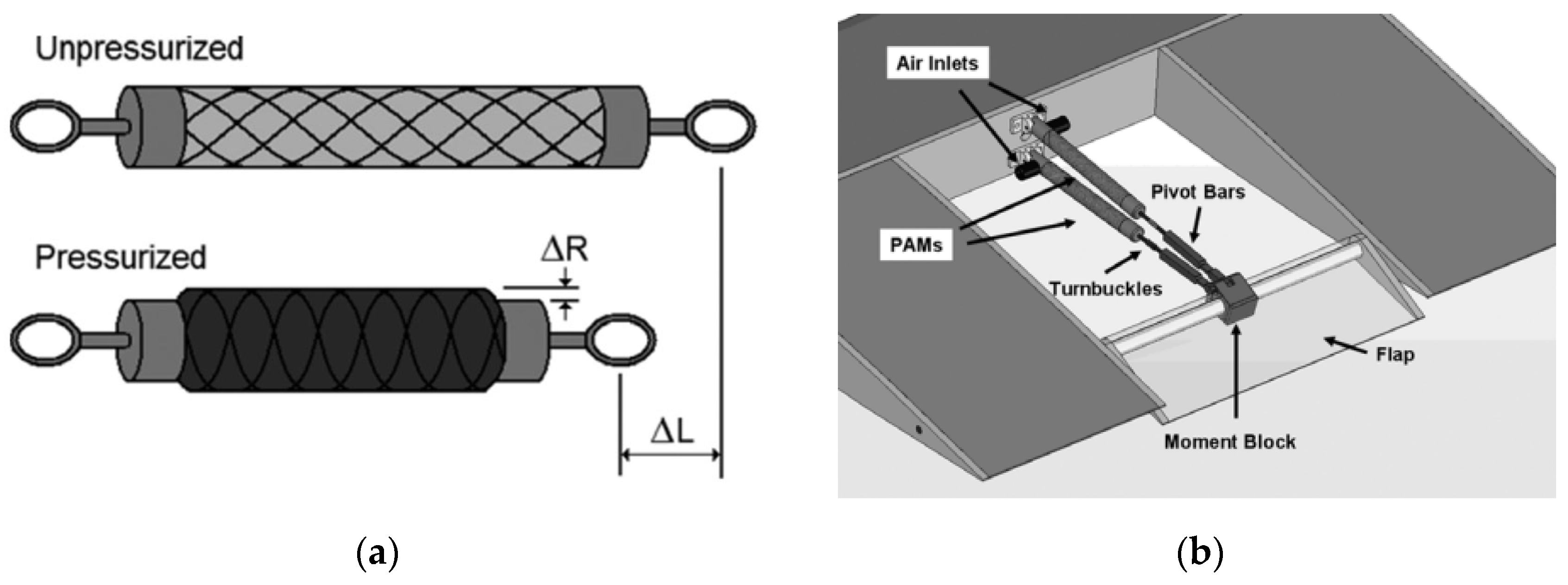
For pneumatic actuators, the flexible body is inflated or discharged to generate the corresponding force. Compared with the electromechanical actuators, they have the advantages of simple structure, easy control, fast driving speed and low cost, but the load capacity and the accuracy are weaker. Therefore, if the driving accuracy and load requirements are not high or the internal space of the structure is not large, the designer can preferentially choose the pneumatic actuators.
(c)
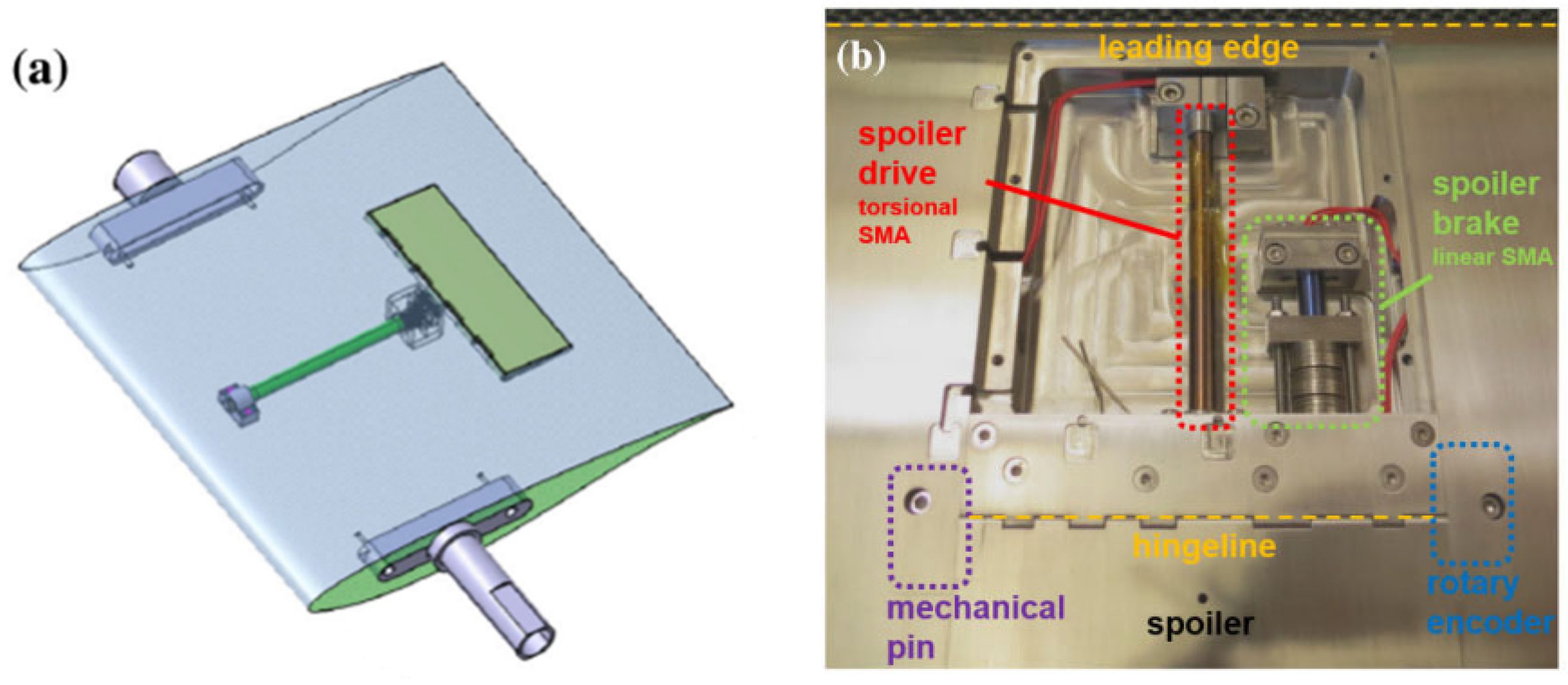
Because of its memory effect, the shape memory alloy has the advantages of high energy density and adaptive deformation capability. Therefore, in the wind tunnel test model of variant aircraft, the design of shape memory materials can make the active part simpler, lighter and more flexible. Compared with piezoelectric materials, it has a larger deformation range. However, shape memory alloys also have many limitations, such as a more complex constitutive, a driving process that is susceptible to the external environment and a very weak control ability of the intermediate state. In addition, due to the different heat treatment process and material composition, the performance of shape memory alloys has a large difference. Therefore, it is difficult to change from a state control to process control, reduce interference from external conditions and obtain an accurate and real-time temperature control algorithm.
(d)
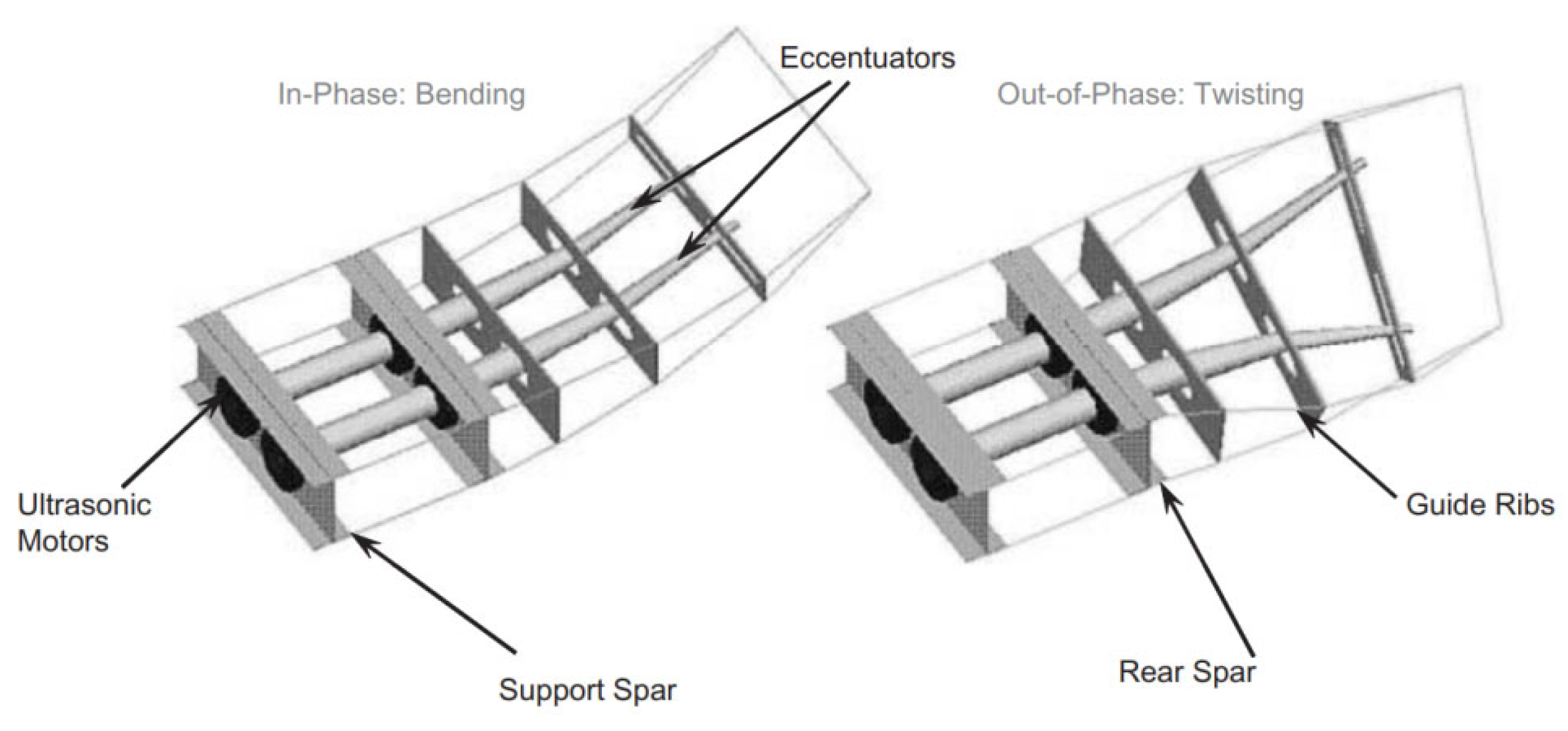
The actuators based on the inverse piezoelectric effect control the deformation of piezoelectric materials by controlling the magnitude of voltage. Compared with shape memory material, they have a more mature control algorithm, simpler constitutive equation and higher precision for small displacement control. Compared with electromechanical actuators, piezoelectric actuators take up an extremely small space and respond faster. In addition, the MFCs can be directly attached to the airfoil surface to drive the control surface. However, due to the characteristics of piezoelectric material, its driving deformation is very small. Therefore, researchers need to design highly efficient displacement amplifying mechanisms, such as bender elements, eccentuators and diamond-shaped amplification structures, to obtain a larger deformation. The appearance of these amplifying structures can greatly improve the output deformation, but they take up a lot more space.

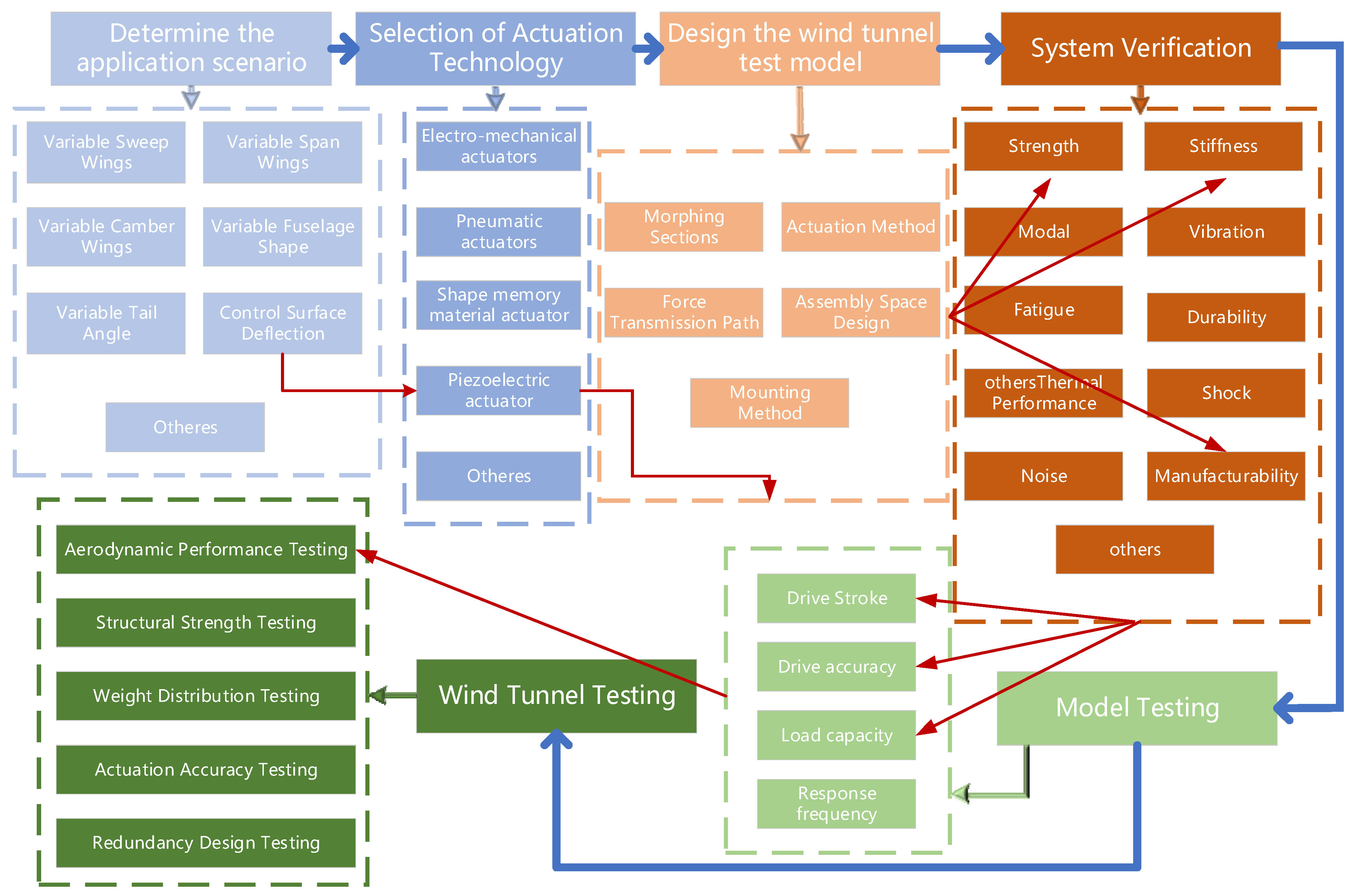
4. Proposed Design Flow and a Case Study

Figure 7 shows the basic design flow of the morphing wind tunnel test model, which includes confirming the application scenario; selecting the drive mechanism that can meet the requirements according to the variant type of the aircraft; completing the design of the model according to the assembly of the wind tunnel test model, fixing methods, parameter test points and structural characteristics of the variant parts; confirming the calibration of several key factors affecting the current variant test model and confirming the feasibility of the scheme through numerical calculation to confirm the feasibility of the scheme; designing and producing the actual variants of the mechanism to carry out the basic operating capacity of the test model to verify that the model can meet the basic operational requirements; and finally, installing the test model in the wind tunnel for testing, to verify the variants of the wind tunnel test model.
In this study, a rudder deflection wind tunnel test model was designed to meet the need for continuous rudder deflection in wind tunnel tests. For the application scenarios, the ultrasonic motor based on the inverse piezoelectric effect was selected as the driving element according to the design flow shown by the red arrows in Figure 7, and a set of mechanical transmission and remote control systems were constructed for the wind tunnel test model. Numerical calculations were carried out to verify the factors affecting the strength and stiffness; a series of ground tests were conducted to confirm that the mechanism could meet the basic needs of wind tunnel tests; and finally, the mechanism was installed in the wind tunnel and the test data were compared with the traditional rudder mechanism, which further illustrated the feasibility of this set of wind tunnel test models based on smart materials.

4.1. Design Requirements

The main purpose of the wind tunnel test is to obtain the accurate flight parameters of the vehicle under various simulated flight states (including wind speed, wind direction, flight attitude and the morphing state of the morphing vehicle), so as to provide data support for the subsequent design and production of the actual vehicle. Therefore, in this study, the following requirements were put forward for the design of the whole wind tunnel test model: the actual structure needed to simplify the complexity of the structure, reduce redundancy and be designed in a modular way, so as to reduce the assembly error of the structure. In the scaled-down model, it was necessary to reserve enough space for the completion of the installation and disassembly of the modules, and at the same time, it was also necessary to ensure sufficient strength and stiffness in order to avoid the destruction of the material and prevent deformation from introducing too much error to the wind tunnel test. The design of the drive needed to provide enough space for the installation and removal of each module. The design of the actuator needed to provide enough driving stroke to meet the test requirements of each state of the wind tunnel test model. It also needed to ensure enough driving force to enable the rudder (or morphing structure) to reach the specified position during the wind tunnel test, and most importantly, the actuator needed to be accurate enough to ensure the accuracy of the test results. In this case, the drive design, structural model design and verification, rudder deflection model testing and wind tunnel testing were carried out.

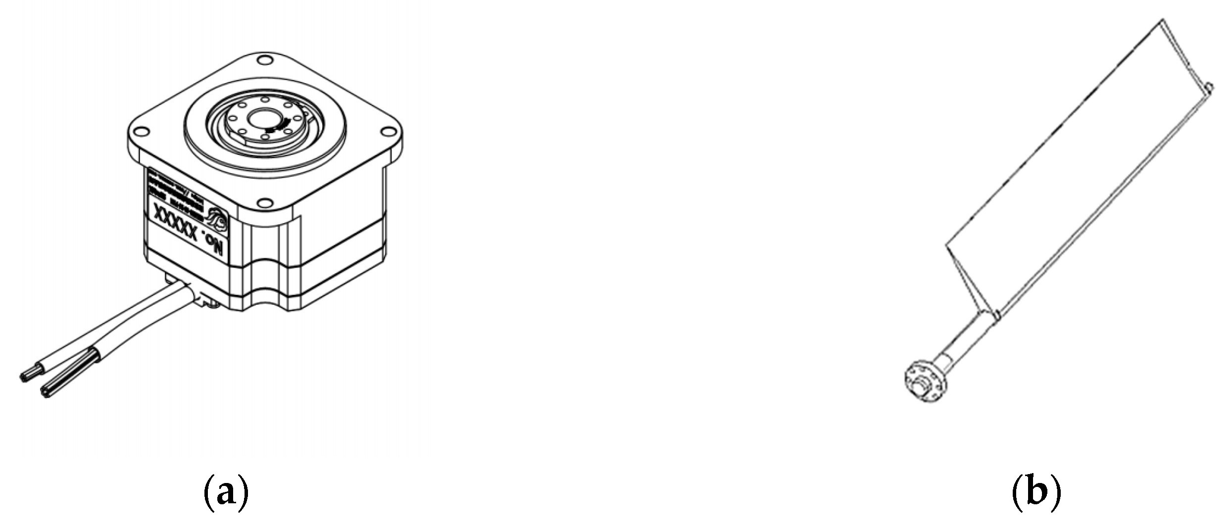
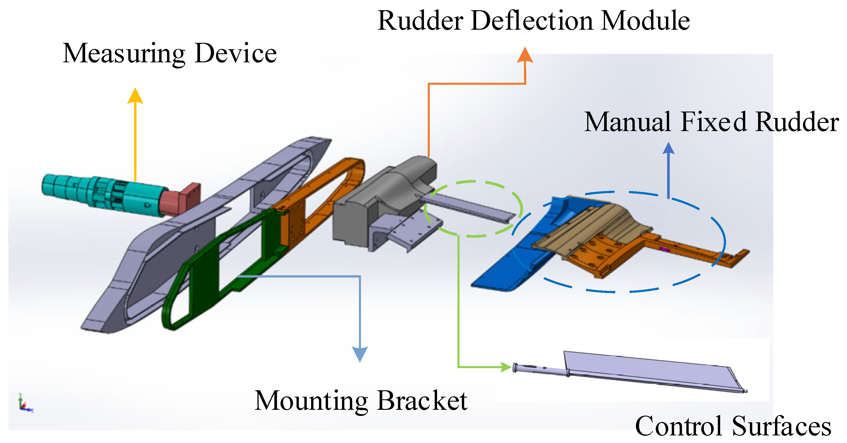
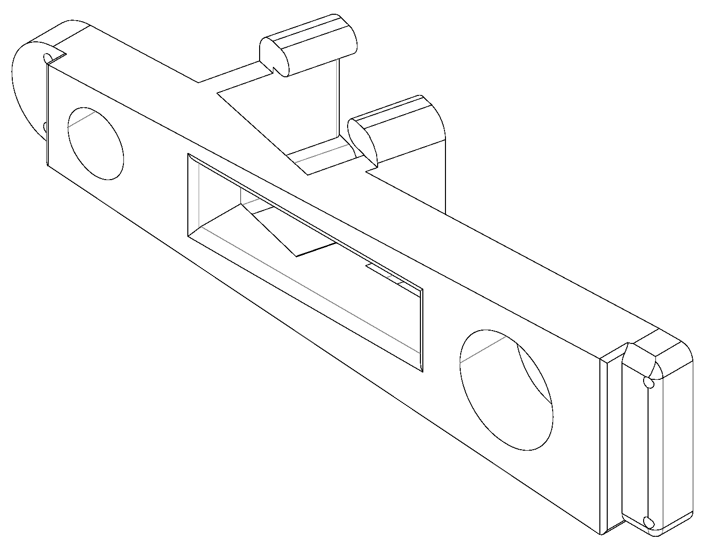
4.2. The Design of the Wind Tunnel Control Surface Deflection Model

Definition: The ultrasonic motor (USM) utilizes the inverse piezoelectric effect of piezoelectric ceramics by controlling the alternating voltage in the electrodes of the pre-arranged piezoelectric ceramic group as well as the phase; the piezoelectric ceramics generate high frequency ultrasonic vibration, which rotates the rotor in the USM through the friction between the stator and rotor. The USM has the advantages of a compact structure, high positional accuracy, fast response speed, large driving stroke, high interference resistance, low speed and high torque, and self-locking in power failure, so it has a wide range of applications in the field of intelligent drive. Given its low speed and high torque, power failure self-locking and other advantages, it has a wide range of applications in the field of intelligent drive [42].
The basic components of a traveling wave USM include a base, a stator made of piezoelectric ceramics, a rotor, bearings, a shaft, a rear shell and other structures. Besides, there are control circuits for controlling the piezoelectric material.
Expanding the above stator structure, the stator and rotor motion transfer conceptual diagram (enlarged) can be obtained as shown in Figure 8. The following is a multi-block piezoelectric ceramic stator part; when the piezoelectric ceramic is connected to the corresponding high-frequency alternating voltage, the material has its own inverse piezoelectric effect, thereby generating a micro-amplitude high-frequency vibration and a stator-integrated piezoelectric ceramics group at a specific frequency. The amplitude of the alternating voltage signals results in the generation of traveling waves along a specific direction of the piezoelectric ceramic group integrated into the stator, under the specific frequency and amplitude of the alternating voltage signal, and then, through the friction plate between the stator and rotor, drives the rotor to rotate, realizing the control of the rotor.
In order to realize the application of USM in the wind tunnel test model, based on the above principle, a USM for wind tunnel test rudder deflection was designed and fabricated, and an encoder was integrated to monitor the real-time deflection angle; the USM model is shown in Figure 9.
The integrated design of the USM can realize the control of the motor’s forward rotation, reverse rotation, emergency stop and other motion modes. In order to ensure that the output angle and torque of the USM is accurately transmitted to the rudder, the flange structure shown in Figure 9 is reserved in the USM, which is combined with the flange on the rudder rotor shaft to realize the coaxial drive of the USM. More specific details of the parameters are shown in Table 2.
In the wind tunnel test model of this study, a measurement balance and mounting bracket were used, and the overall structural layout is shown in Figure 10. It was necessary to test the response of each deflection angle of the specified rudder surface in the wind tunnel experiment. Therefore, it was necessary to design an additional installation module that plays a connecting role. The layout and positioning of the USM in the installation module connects the entire module to the device already available in the wind tunnel test model. In order to verify the correctness of the rudder deflection angle of the automatic system, a fixed rudder with the same interface was designed for comparison and verification.
With the goal of making full use of the internal space of the wind tunnel model, maximizing the use of space and minimizing the weight of the parts, the mounting module was designed as shown in Figure 11. In order to adapt to the main body of the balance in the wind tunnel model and reduce the installation error, the structure had a certain degree of irregularity, and aluminum alloy was selected as the machining material, which was processed by CNC machine tools.
In order to ensure that the designed structure meets the basic reliability and safety requirements, this study adopted the finite element method to comprehensively simulate the strength of the mounting module, the USM and the rudder structure, and carried out a finite element analysis by establishing an accurate geometric model and determining the material properties of each part, as well as the applicable boundary conditions.
An aluminum alloy was selected for the mounting module, Q235 was selected for the motor as well as the bolts that played a fixed role and 30CrMnSiA was used for the rudder surface material, and the specific material parameters are shown in Table 3. Considering that the whole model would be mounted in the mounting bracket of the wind tunnel test model, the overall multi-flexible bodies simulation of the mounting module, the USM and the rudder surface was carried out, and the fixed boundary conditions were set on the mounting module. Binding connections were used between the rudder surface and the USM, and between the USM and the mounting module. After calculation, the current rudder model, under the specified wind tunnel test scenario, was subjected to loads at each deflection angle that did not exceed the equivalent torque of 18 Nm. Therefore, the load boundary suite was set up with 18 Nm loads at the upper and lower ends of the rudder surface. The calculation results are shown in Figure 12 and Figure 13.
According to the simulation results, under the specified wind tunnel test environment, the limiting torque was applied to the rudder, and the maximum stress location occurred at the position of the rotary axis where the rudder was connected to the USM, and the maximum stress was 283.3 MPa, which was much lower than the yield limit of all of the materials, which indicates that the structure had a good safety margin under the current operating conditions. In addition, the stress distribution of the whole structure showed that the stress level of the motor and the mounting module was low, which also showed the rationality of the current structure design. From the displacement map, it could be seen that the maximum displacement occurs at the trailing edge of the rudder when the set limit load was applied, and the maximum displacement was 0.0049 mm, which was much smaller than the design target of the current wind tunnel test, and at the same time, the distribution of the displacement showed a uniform pattern, which indicated that the overall stiffness of the structure met the requirements.
Combining the design of the USM, the mounting module and the design and analysis of the rudder, it could be concluded that the USM components in this study maintain good load carrying capacity and structural stiffness under the most extreme wind tunnel test loads. This also indicated that the current structure could meet its safety as well as operational performance requirements in wind tunnel tests.
For the above mechanism to realize remote active control of rudder deflection in the wind tunnel test, it was also necessary to set up a matching measurement and control system for the USM. The system needed to monitor the USM output torsion angle in real time through the built-in encoder and feed it back to the control system, and through the PID control algorithm that had completed the debugging, it needed to output target control signals to the USM, so as to realize precise control of the rudder angle of the USM in the wind tunnel test.
In the control program designed on the LabVIEW platform, the initialization adjustments of the USM, motor speed control, real-time angle display, error range setting and parameters KP, KI and KD, as well as a reading of the amplitude of the output signal, the relative deflection angle, the real-time error and other information, and other functions could be achieved.
The principle of the measurement and control system is shown in Figure 14, the control system described in this paper was a real-time closed-loop control system, the program would be based on the user inputting the desired angle value in order to calculate the USM actually needed to deflect the angle, automatically calculating the shortest deflection angle of the motor and the direction of the rotation of the motor to control the motor forward and reverse, as well as based on real-time angular error for real-time speed regulation of the motor, and could be based on user-specified time thresholds, to avoid damage to the motor due to overloading and other reasons for the motor blocking the motor and the overtime; the program would automatically allow the motor to stop the motor rotation, so as to protect the motor.
For the state machine of USM control, there were ten main modes, which were divided into motor speed setting, start closed-loop, start rotation, forward rotation, emergency stop, stop, exit, reverse rotation, zero adjustment and the initialization of the motor. For different state machines, there would be different command inputs, for example, the stop command, which would force the current motion process to stop when the host computer sent a frame of the stop command to the driver.

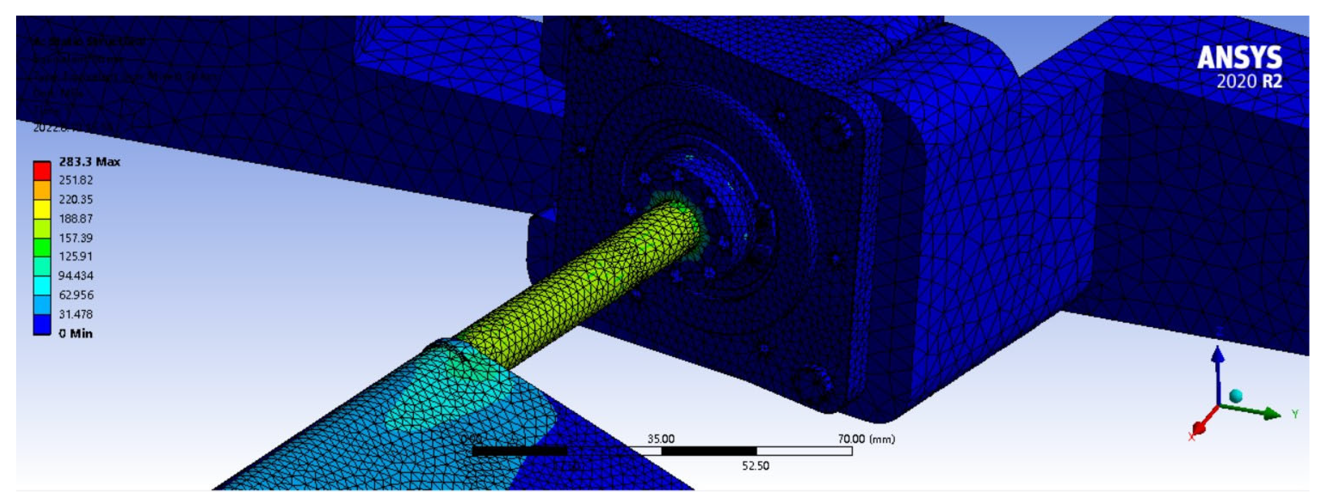
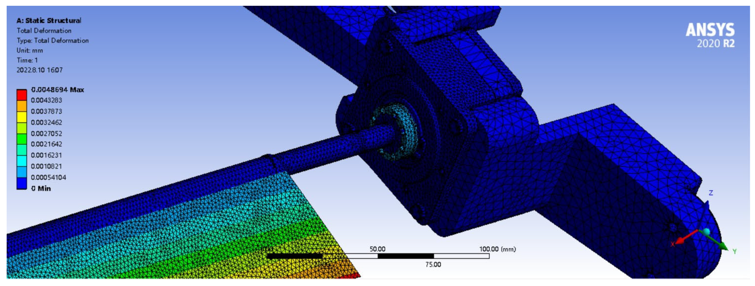
4.3. Load Capacity Test
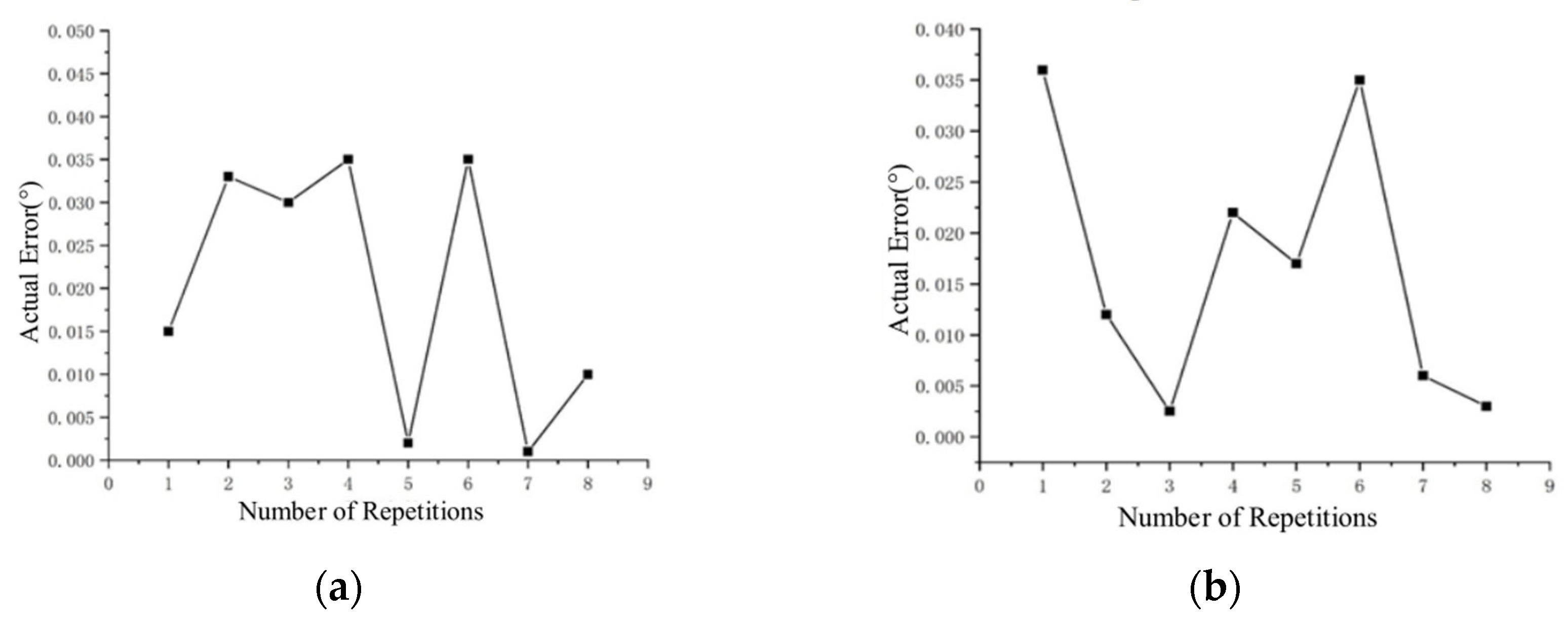
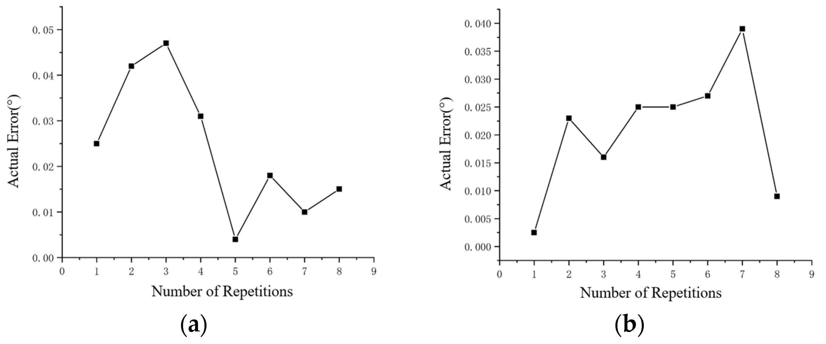
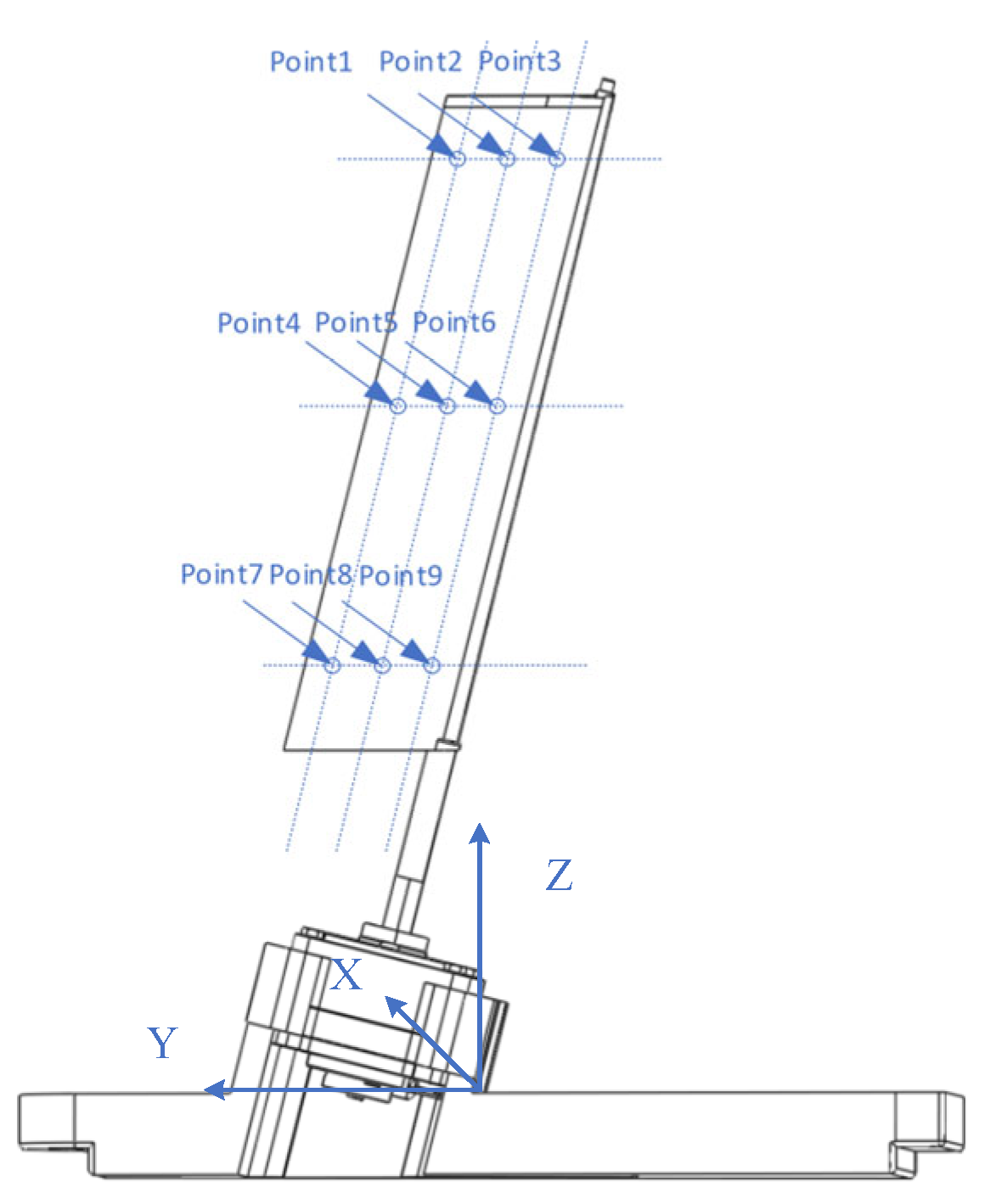
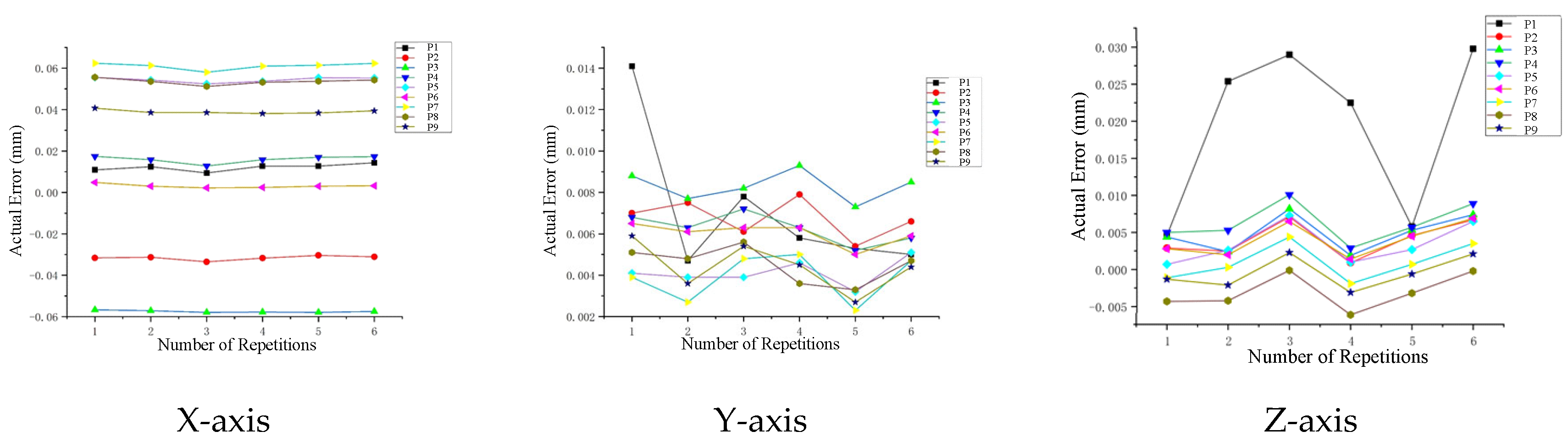
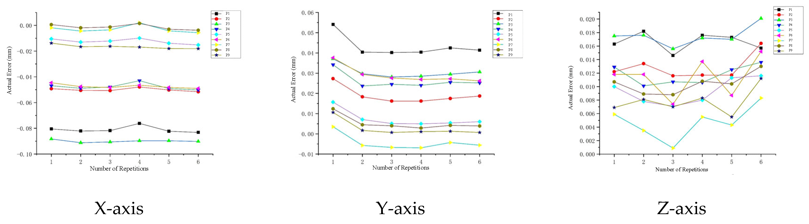
The wind tunnel test of rudder deflection was designed to test the response at each deflection angle, and the ability of the rudder to accurately reach the specified deflection angle determined the accuracy of this wind tunnel test study. Therefore, in this study, it was necessary to ensure that the USM could reach the specified deflection position under load. The first part of the tests was under no-load conditions, the second part was under extreme aerodynamic load (18 Nm).
Before that, the deflection test under no load was completed, the deflection angle was set through the host computer and several deflection tests were carried out, which were 20° forward and 20° reverse; the error range was set to 0.05° and the actual error of each deflection was read. The records are shown in Figure 15.
The test results showed that the USM paired with the measurement and control system in this study was able to achieve output angle deflection control within the error range (0~0.05°), and the actual maximum deviation was 0.048° for the third test in the case of positive rotation. Of course, this error range was only the preset maximum error value, and the system could further set the required error limit according to the needs of specific wind tunnel test scenarios.
Under no load, the rudder deflection system was able to complete the deflection at a specified angle to test its deflection accuracy under the current wind tunnel test limit load. Similar to the above no-load test procedure, the deflection test was conducted under load, and the output shaft was loaded in the form of a mount in the ground test.
Following the loading pattern as shown in Figure 16, different deflection angles of the rudder corresponded to different equivalent moment arms. In order to ensure that the maximum loading conditions were met at each deflection angle, the torque of 18 Nm was loaded on the rudder with the smallest moment arm. The torque was obtained by applying a force load of 300 N to the trailing edge of the rudder. The load capacities of USM were above the maximum torque required by the wind tunnel test throughout the course of the deflection angle output, i.e., from 0° to 20°, or from 0° to −20°.
Similar to the no-load test results, as shown in Figure 17, the actual errors remained within the set error allowance during the eight repetitions of the test. This indicates that the USM described in this study was capable of performing the actual remote controllable continuous deflection test from a load perspective under the current test environment of the required wind tunnel test.

4.4. Accuracy Test

In order to further determine the control accuracy of the USM rudder deflection system described in this study, on the basis of the original encoder to monitor the deflection angle, an external three-coordinate angle monitoring was carried out. The USM was installed into the mounting module, and after completing the fixation, the high precision machined rudder surface was connected, and the current USM and the position in which the motor was located were calibrated using the three-coordinate system shown in Figure 18.
After the current reference position was determined by the coordinate system, nine measurement points from the root to the tail and from the leading edge to the trailing edge were marked on the rudder surface as the reference positions before and after the deflection, and the specific marked positions are shown in Figure 19. Firstly, the position coordinates of the marked points after the rudder surface deflection could be calculated by the geometric structure of the model, and then the rudder surface could be deflected to the specified angle by the USM drive, and then the coordinates of the marked points could be measured by using the coordinate system, and the error between the actual points and the calculated points could be compared.
To ensure the accuracy of the tests, three sets of tests were randomly selected to deflect the rudder from 15° to 0°, 0° to 15°, and 15° to −30°, and were repeated six times. The actual coordinate values of the marked points after deflection were tested using a coordinate measuring system. The measurement results are shown below.
According to the test results from 15° to 0° (Figure 20), the rudder arrives at each point with high positional accuracy, and the three-axis positional error was greatest in the X-axis at the end of the rotary axis, point 3, and the trailing edge of the rudder, point 7, which showed the greatest forward and reverse deviation, and the absolute value of deviation in multiple tests was around 0.06 mm, while the Y-axis and Z-axis had a deviation of ±0.02 mm; according to the test results from 0° to 15° (Figure 21), the maximum deviation was at point 1 and point 3 at the end of the rotary axis. At 15° (Figure 21), the maximum deviation was at point 1 and point 3 at the end of the rotary axis, and the error range of all of the tested points was between −0.1 and 0.06; in the maximum travelling test result (Figure 22), from 15° to −30°, the deviation on the X-axis was similar to that of the abovementioned point 3 at the end of the rotary axis and point 7 at the rudder’s trailing edge during the process of turning from 15° to 0°, but this time, all of them showed a positive error. The maximum error for multiple tests was around 0.12 mm. In three sets of 18 tests, the errors were much smaller than the designed allowable error of ±0.2 mm, which indicated that the wind tunnel rudder deflection test model based on the USM was feasible.

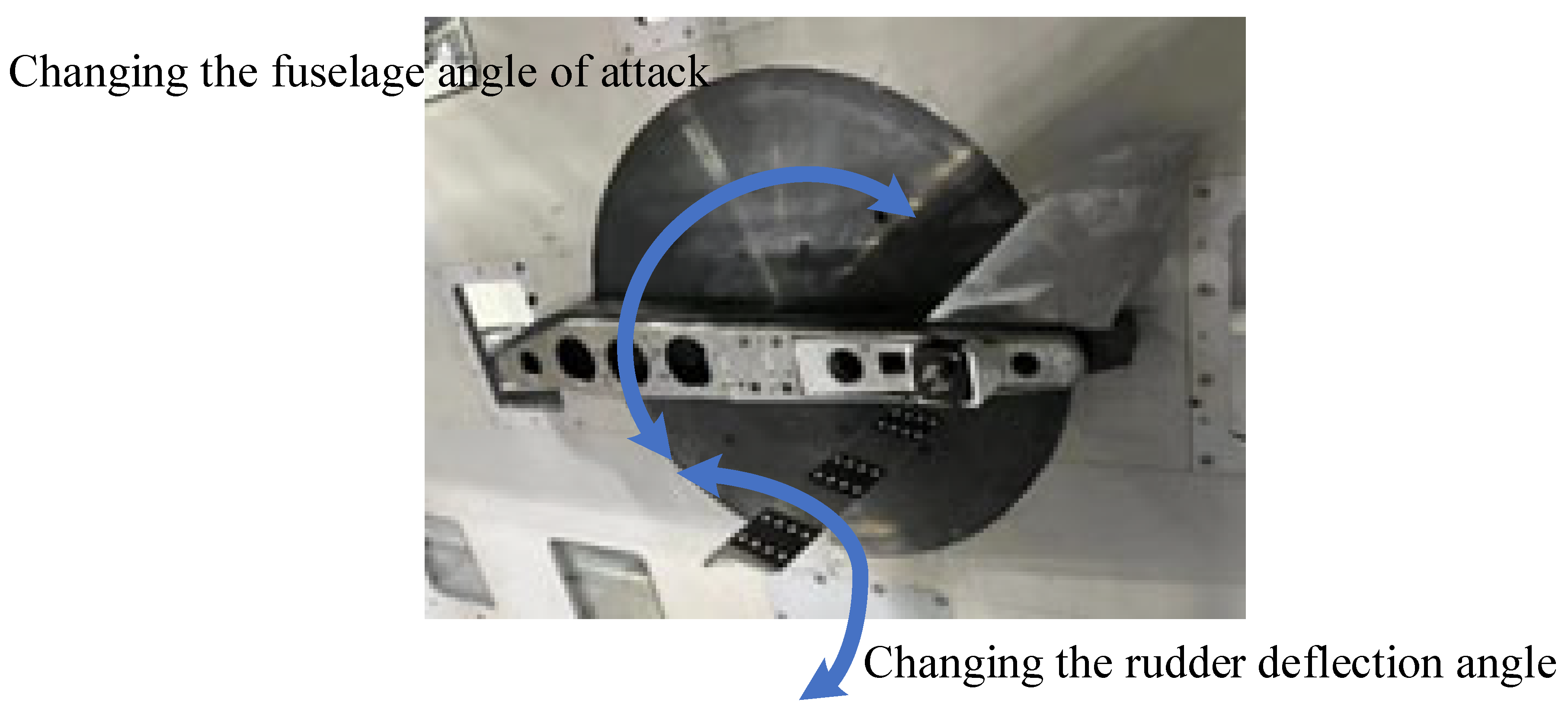
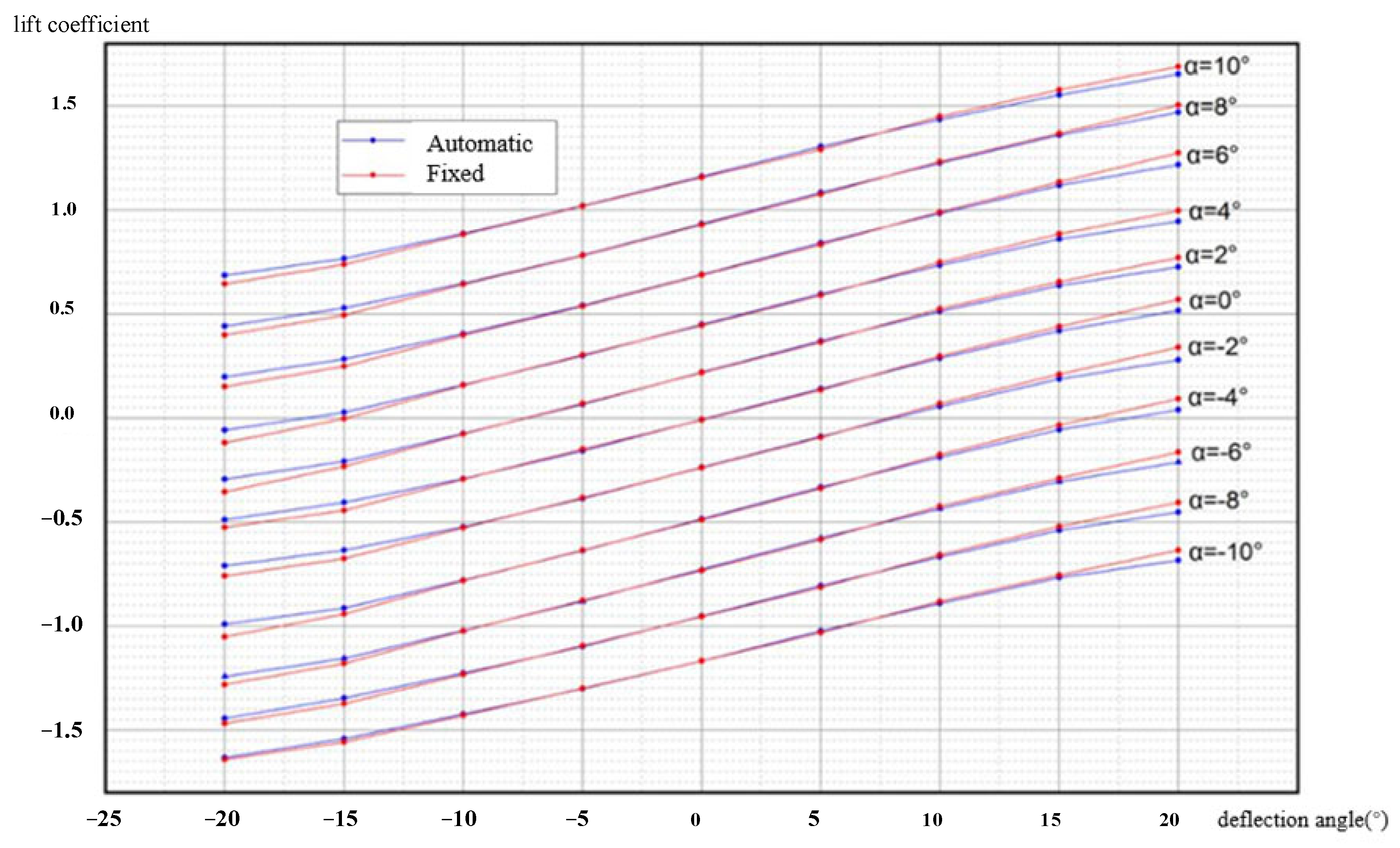
4.5. The Wind Tunnel Test

Manually changing the deflection angle of the rudder, which is guaranteed by the existing measuring device, can relatively accurately place the rudder at the specified angle for the wind tunnel test and then complete the corresponding parameter test, but its complicated and cumbersome installation, dismantling and shutdown processes seriously affect the efficiency of the wind tunnel test. Therefore, the USM described in this study was designed and manufactured. To further verify the effectiveness and accuracy of the USM in the wind tunnel test, the USM-based wind tunnel test model was compared with the manually mounted angle piece wind tunnel test model. The installation of the USM with a mounting module, support device and measuring balance is completed, and the installed form in the wind tunnel is shown in Figure 23. The accuracy of the manual method was tested against the remote automatic drive method.
In order to verify the rudder deflection accuracy USM actuation, and to verify the lift characteristics under USM actuation in multiple flight attitudes compared to manually adjusted rudder deflection, the following experiments are carried out in this paper. Firstly, the flight attitude was changed by changing the fuselage angle of attack, which ranges from −10° to 10°. Then, under each fuselage angle, the rudder deflection angle was changed manually and by USM control, and the lift coefficient was tested when the rudder deflection angle was from −20° to 20°.
With the existing measuring device, it could be ensured that the angle of attack of the rudder and the rudder deflection angle under the current manual state were within the permissible error range, and the lift coefficient curve obtained from the test is shown in Figure 24. At the same angle of attack, the lift coefficients embodied in the manual adjustment and the USM adjustment reflect a good degree of agreement. However, it can be observed that as the degree of rudder deflection increases, the two gradually produce a small amount of deviation. Negative rudder deflections (−15° to −20°) show higher lift coefficients for the automatic changes than for the manual fixes, while positive rudder angles (15° to 20°) show smaller lift coefficients. With USM, when the rudder is subjected to aerodynamic loads, its fixation of the rudder cannot reach the effect of manual fixation, and both positive and negative deflections are partially insufficient from the specified deflection angle, so in the −20° position, the angle of automatic deflection is larger than −20°, i.e., it exhibits larger lift coefficients, whereas in the 20° position, the angle of automatic deflection is smaller than 20°, and thus it exhibits a smaller lift coefficient. However, when combined with the applications faced, the errors produced by the USM are acceptable.

5. Conclusions

This paper reviews the application of smart materials and smart structure actuation technology, including electromechanical actuation, pneumatic technology, SMA actuation and piezoelectric actuation, in the morphing wind tunnel test model. The application methods of the above four smart materials in the field of morphing actuation are introduced, and according to the actuation characteristics of the root smart structure actuator, considering the morphing mode of the wind tunnel test model, a comprehensive selection of one or a combination of multiple smart materials designed actuators is made to realize the morphing actuation of the test model. The unique advantages of several smart material actuators for several special application scenarios are summarized, as well as the shortcomings of several materials, and the selection of smart actuator structures is carried out under the priority of the influencing factors such as stroke, force, frequency, control mode and the degree of structural simplification. A foundation is laid for exploring new morphing mechanisms for subsequent wind tunnel test models.
Meanwhile, for the application scenarios such as remote, continuous and high-precision rudder deflection in the wind tunnel test, which can be self-locking under aerodynamic load, an ultrasonic motor actuator based on the inverse piezoelectric effect of piezoelectric materials is introduced, which explores a new actuation method of smart materials, and effectively solves the problem of the short stroke of piezoelectric materials. The ground test and wind tunnel test results of the case show that the ultrasonic motor is able to output the actuating stroke required for the rudder deflection of this wind tunnel test model as well as the control accuracy, and also has sufficient self-locking capability. This effectively improves the efficiency of the wind tunnel test and accelerates the subsequent design process of the whole aircraft.
Although smart material actuators have been used in a wide range of applications, and some of the products have a huge commercial value, these actuators still have technical challenges waiting to be solved. These include, for instance, the simplification of the structure of the electromechanical drive; more accurate temperature control of SMA drives, matching more types of intrinsic models, and the need for more process control of SMAs; and for piezoelectric materials, the need for control algorithms that are constantly being optimized, and so on. Nevertheless, as more researchers are involved in the development and exploration of smart materials and smart structures, various new forms of applications are constantly being proposed, excellent materials are being discovered, more precise and efficient control systems are being developed and more mature and perfect applications of these smart materials and smart structure actuators can be realized in the near future.

Author Contributions

Conceptualization, G.P., P.S. and B.W.; methodology, G.P., X.C., P.S. and B.W.; software, G.P.; validation, P.S. and B.W.; formal analysis, G.P.; investigation, G.P. and X.C.; resources, X.C., P.S. and B.W.; data curation, G.P. and X.C.; writing—original draft preparation, G.P.; writing—review and editing, B.W.; visualization, X.C. and P.S.; supervision, X.C., P.S. and B.W.; project administration, G.P. All authors have read and agreed to the published version of the manuscript.

Funding

This research received no external funding.

Data Availability Statement

The data presented in this study are available on request from the corresponding author.

Conflicts of Interest

The authors declare no conflicts of interest.

References

  1. Gudmundsson, S. General Aviation Aircraft Design: Applied Methods and Procedures; Butterworth-Heinemann: Oxford, UK, 2013. [Google Scholar]
  2. Barlow Jewel, B.; Rae William, H.; Pope, A. Low-speed wind tunnel testing; John Wiley & Sons: New York, NY, USA, 1999. [Google Scholar]
  3. Roberts, R.; Smith, C. Improving remote control applications for wind tunnel tests. US Air Force TE Days 2009, 2009, 1753. [Google Scholar]
  4. Calkins, F.T.; Nicholson, D.E.; VonDeetzen, S.; Wright, M.; Cramer, C.; Griffiths, R.; Muller, M.; Sleppy, M.A.; Saxer, D.R.; Lafranchi, A.; et al. Low & high speed cryogenic testing of a wind tunnel model with remote control actuation (RCA) spoiler. In Proceedings of the AIAA Aviation 2019 Forum, Dallas, TX, USA, 17–21 June 2019. [Google Scholar]
  5. Barbarino, S.; Bilgen, O.; Ajaj, R.M.; Friswell, M.I.; Inman, D.J. A review of morphing aircraft. J. Intell. Mater. Syst. Struct. 2011, 22, 823–877. [Google Scholar] [CrossRef]
  6. Sun, J.; Guan, Q.; Liu, Y.; Leng, J. Morphing aircraft based on smart materials and structures: A state-of-the-art review. J. Intell. Mater. Syst. Struct. 2016, 27, 2289–2312. [Google Scholar] [CrossRef]
  7. Nguyen, N.T.; Cramer, N.B.; Hashemi, K.E.; Ting, E.; Drew, M.; Wise, R.; Boskovic, J.; Precup, N.; Mundt, T.; Livne, E.; et al. Real-Time Adaptive Drag Minimization Wind Tunnel Investigation of a Flexible Wing with Variable Camber Continuous Trailing Edge Flap System. In Proceedings of the AIAA Aviation 2019 Forum, Dallas, TX, USA, 17–21 June 2019. [Google Scholar]
  8. Pecora, R.; Amoroso, F.; Sicim, M.S. Design of a Morphing Test-Article for Large-Scale, High-Speed Wind Tunnel Tests of an Adaptive Wing Flap. In Active and Passive Smart Structures and Integrated Systems XV; SPIE: Bellingham, WA, USA, 2021; Volume 11588. [Google Scholar]
  9. Arena, M.; Concilio, A.; Pecora, R. Aero-servo-elastic design of a morphing wing trailing edge system for enhanced cruise performance. Aerosp. Sci. Technol. 2019, 86, 215–235. [Google Scholar] [CrossRef]
  10. Vasista, S.; Riemenschneider, J.; Monner, H.P. Design and testing of a compliant mechanism-based demonstrator for a droop-nose morphing device. In Proceedings of the 23rd AIAA/AHS Adaptive Structures Conference, Kissimmee, FL, USA, 5–9 January 2015. [Google Scholar]
  11. Liang, J.L.; Wang, X.; Zhang, R.P.; Gao, D.P. Optimization design and development of transmission mechanism for small electric steering system. Mech. Res. Appl. 2016, 29, 110–113. [Google Scholar]
  12. Dong, G.Q.; Li, Q.; Li, Z.F.; Xu, L.J.; Liu, X.H. Research on automatic variable-angle system of the buried motivator. J. Exp. Fluid Mech. 2010, 24, 73–76. [Google Scholar]
  13. Woods, B.K.S.; Kothera, C.S.; Sirohi, J.; Wereley, N.M. Pneumatic artificial muscles for trailing edge flap actuation: A feasibility study. Smart Mater. Struct. 2011, 20, 105021. [Google Scholar] [CrossRef]
  14. Peel, L.D.; Meija, J.; Narvaez, B.; Thompson, K.; Lingala, M. Development of a simple morphing wing using elastomeric composites as skins and actuators. J. Mech. Des. 2009, 131, 091003. [Google Scholar] [CrossRef]
  15. Zhou, H.; Plummer, A.R.; Cleaver, D. Distributed Actuation and Control of a Tensegrity-Based Morphing Wing. IEEE/ASME Trans. Mechatron. 2021, 27, 34–45. [Google Scholar] [CrossRef]
  16. Yin, W.; Liu, L.; Chen, Y.; Liu, Y.; Leng, J. Pneumatic Artificial Muscle and Its Application on Driving Variable Trailing-Edge Camber Wing. In Industrial and Commercial Applications of Smart Structures Technologies 2010; SPIE: Bellingham, WA, USA, 2010; Volume 7645. [Google Scholar]
  17. Jardine, A.P.; Bartley-Cho, J.D.; Flanagan, J.S. Improved Design and Performance of the SMA Torque Tube for the DARPA Smart Wing Program. In Smart Structures and Materials 1999: Industrial and Commercial Applications of Smart Structures Technologies; SPIE: Bellingham, WA, USA, 1999; Volume 3674. [Google Scholar]
  18. Karagiannis, D.; Stamatelos, D.; Spathopoulos, T.; Solomou, A.; Machairas, T.; Chrysohoidis, N.; Saravanos, D.; Kappatos, V. Airfoil morphing based on SMA actuation technology. Aircr. Eng. Aerosp. Technol. Int. J. 2014, 86, 295–306. [Google Scholar] [CrossRef]
  19. Sinn, T.; Barrett, R. Design, manufacturing and test of a high lift secondary flight control surface with shape memory alloy post-buckled precompressed actuators. Actuators 2015, 4, 156–171. [Google Scholar] [CrossRef]
  20. Han, M.-W.; Rodrigue, H.; Kim, H.-I.; Song, S.-H.; Ahn, S.-H. Shape memory alloy/glass fiber woven composite for soft morphing winglets of unmanned aerial vehicles. Compos. Struct. 2016, 140, 202–212. [Google Scholar] [CrossRef]
  21. Yin, W.; Fu, T.; Liu, J.; Leng, J. Structural Shape Sensing for Variable Camber Wing Using FBG Sensors. In Sensors and Smart Structures Technologies for Civil, Mechanical, and Aerospace Systems 2009; SPIE: Bellingham, WA, USA, 2009; Volume 7292. [Google Scholar]
  22. Li, J.; Qin, Y.-H.; Bai, T.; Yu, Z.-H. Development of a morphing wing with adaptive capability. Acta Aerodyn. Sin. 2009, 27, 505–508. [Google Scholar]
  23. Li, W.; Xiong, K.; Chen, H.; Zhang, X.; Su, Y.; Ren, Z. Research on variable cant angle winglets with shape memory alloy spring actuators. Acta Aerodyn. Sin. 2012, 33, 22–33. [Google Scholar]
  24. Lei, P. Design and High Speed Wind Tunnel Test of Morphing Wing Model Based in Intelligent Structure. Master’s Thesis, China Aerodynamics Research and Development Center, Mianyang, China, 2016. [Google Scholar]
  25. Benafan, O.; Moholt, M.R.; Bass, M.; Mabe, J.H.; Nicholson, D.E.; Calkins, F.T. Recent advancements in rotary shape memory alloy actuators for aeronautics. Shape Mem. Superelasticity 2019, 5, 415–428. [Google Scholar] [CrossRef]
  26. Sahoo, D.; Cesnik, C. Roll maneuver control of UCAV wing using anisotropic piezoelectric actuators. In Proceedings of the 43rd AIAA/ASME/ASCE/AHS/ASC Structures, Structural Dynamics, and Materials Conference, Denver, CO, USA, 22–25 April 2002. AIAA-2002-1720. [Google Scholar]
  27. Wilbur, M.L.; Wilkie, W.K. Active-twist rotor control applications for UAVs. In Transformational Science and Technology for the Current and Future Force: (With CD-ROM); World Scientific Publishing Co Pte Ltd.: Singapore, 2006; pp. 185–192. [Google Scholar]
  28. Detrick, M.; Washington, G. Modeling and design of a morphing wing for micro unmanned aerial vehicles via active twist. In Proceedings of the 48th AIAA/ASME/ASCE/AHS/ASC Structures, Structural Dynamics, and Materials Conference, Honolulu, HI, USA, 23–26 April 2007. [Google Scholar]
  29. Prazenica, R.J.; Kim, D.; Moncayo, H.; Azizi, B.; Chan, M. Design, characterization, and testing of macro-fiber composite actuators for integration on a fixed-wing UAV. In Active and Passive Smart Structures and Integrated Systems 2014; SPIE: Bellingham, WA, USA, 2014; Volume 9057. [Google Scholar]
  30. Wang, D.P.; Bartley-Cho, J.D.; Martin, C.A.; Hallam, B.J. Development of high-rate large-deflection hingeless trailing-edge control surface for the Smart Wing wind tunnel model. In Smart Structures and Materials 2001: Industrial and Commercial Ap-plications of Smart Structures Technologies; SPIE: Bellingham, WA, USA, 2001; Volume 4332. [Google Scholar]
  31. Kimaru, J.; Bouferrouk, A. Design, manufacture and test of a camber morphing wing using MFC actuated mart rib. In Proceedings of the 2017 8th International Conference on Mechanical and Aerospace Engineering (ICMAE), Prague, Czech Republic, 22–25 July 2017. [Google Scholar]
  32. Lu, Q. Helicopter Active Trailing-Edge Flap with Piezoelectric Actuator; Harbin Institute of Technology: Harbin, China, 2013. [Google Scholar]
  33. Li, C.; Sun, S.; Niu, B.; Yang, R. Study on active deformation of deformable wing shrinkage ratio model under drive of MFC. Piezoelectr. Acoustoopt. 2018, 40, 104–107. [Google Scholar]
  34. Zhang, Z.; Huang, W.; Yang, W. Design analysis and test of smart rotor blades model with trailing edge flaps. J. Nanjing Univ. Aeronaut. Astronaut. 2011, 43, 296–301. [Google Scholar]
  35. Bartley-Cho, J.D.; Wang, D.P.; Martin, C.A.; Kudva, J.N.; West, M.N. Development of high-rate, adaptive trailing edge control surface for the smart wing phase 2 wind tunnel model. J. Intell. Mater. Syst. Struct. 2004, 15, 279–291. [Google Scholar] [CrossRef]
  36. Das, H.; Bao, X.; Bar-Cohen, Y.; Bonitz, R.; Lindemann, R.A.; Maimone, M.; Nesnas, I.A.; Voorhees, C.J. Robot Manipulator Technologies for Planetary Exploration. In Smart Structures and Materials 1999: Smart Structures and Integrated Systems; SPIE: Bellingham, WA, USA, 1999; Volume 3668. [Google Scholar]
  37. Sun, Z.; Zhang, T.; Zhang, H.; Jia, Y.; Shen, Z. The technical design and achievements of Chang’E-3 probe. Sci. Sin. Technol. 2014, 44, 331–343. [Google Scholar]
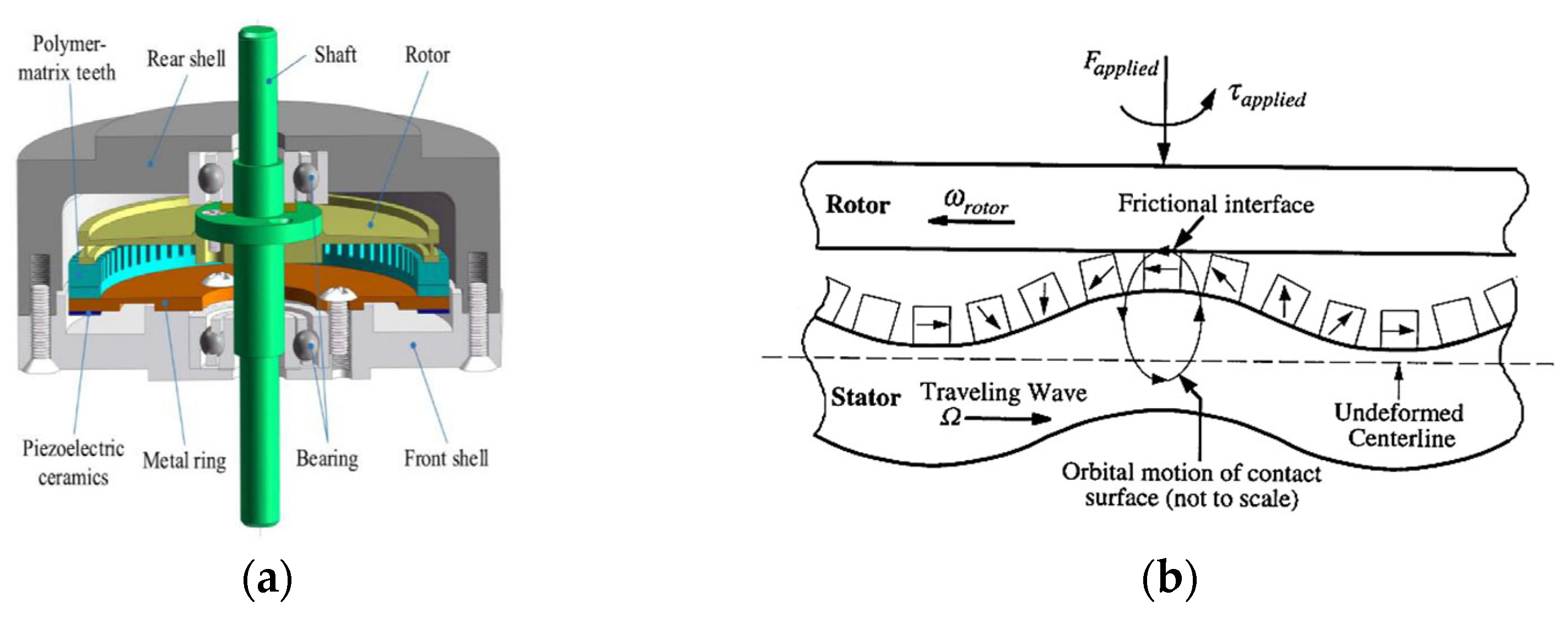
  38. Li, J.; Liu, S.; Zhou, N.; Yu, A.; Cui, Y.; Chen, P. A traveling wave ultrasonic motor with a metal/polymer-matrix material compound stator. Smart Mater. Struct. 2017, 27, 015027. [Google Scholar] [CrossRef]
  39. Lederlé, S. Issues in the Design of Shape Memory Alloy Actuators. Ph.D. Dissertation, Massachusetts Institute of Technology, Cambridge, MA, USA, 2002. [Google Scholar]
  40. Hunter, I.W.; Hollerbach, J.M.; Ballantyne, J. A comparative analysis of actuator technologies for robotics. Robot. Rev. 1991, 2, 299–342. [Google Scholar]
  41. Tadesse, Y. Electroactive polymer and shape memory alloy actuators in biomimetics and humanoids. In Electroactive Polymer Actuators and Devices (EAPAD) 2013; SPIE: Bellingham, WA, USA, 2013; Volume 8687. [Google Scholar]
  42. Li, X.; Wen, Z.; Jia, B.; Cao, T.; Yu, D.; Wu, D. A review of application and development trends in ultrasonic motors. ES Mater. Manuf. 2020, 12, 3–16. [Google Scholar] [CrossRef]
  43. Hagood, N.W.; McFarland, A.J. Modeling of a piezoelectric rotary ultrasonic motor. In Smart Structures and Materials 1994: Smart Structures and Intelligent Systems; SPIE: Bellingham, WA, USA, 1994; Volume 2190. [Google Scholar]
Figure 1. Manual adjustments to the control surface.
Aerospace 11 00666 g001
Figure 2. Typical morphing wing wind tunnel test model system.
Aerospace 11 00666 g002
Figure 3. The CleanSky Camber Morph. Flap (CMF) [8]: (a) the layout of CMF and (b) actuation transmission stages.
Aerospace 11 00666 g003
Figure 4. The operating principle of PAM actuation and flap/actuator system design [13]. (a) The geometric structure of two antagonistic pneumatic actuators. (b) Pneumatically actuated flap deflection device.
Aerospace 11 00666 g004
Figure 5. A 2D airfoil with an RCA spoiler including the planform using SMA elements and sensors [25]. (a) A conceptual model of flap deflection based on SMA torque tube. (b) A solid internal structural model of the SMA torque tube actuator.
Aerospace 11 00666 g005
Figure 6. Trailing edge segment design incorporating two eccentuators [30].
Aerospace 11 00666 g006
Figure 7. Design flow of wind tunnel test models for morphing aircraft.
Aerospace 11 00666 g007
Figure 8. The basic composition of an ultrasonic motor and its principle of operation [38,43]. (a) A schematic diagram of the USM structure. (b) The operating principle diagram of the USM.
Aerospace 11 00666 g008
Figure 9. An ultrasonic motor based on the inverse piezoelectric effect and a control surface with flange. (a) Ultrasonic motor model. (b) Control surface model.
Aerospace 11 00666 g009
Figure 10. Wind tunnel test model.
Aerospace 11 00666 g010
Figure 11. Installation module.
Aerospace 11 00666 g011
Figure 12. The stress distribution of USM under specific loads.
Aerospace 11 00666 g012
Figure 13. The displacement distribution of USM under specific loads.
Aerospace 11 00666 g013
Figure 14. A schematic diagram of the measurement and control system.
Aerospace 11 00666 g014
Figure 15. Results of the no-load deflection test. (a) The +20° rotation test. (b) The −20° rotation test.
Aerospace 11 00666 g015
Figure 16. The load schematic model.
Aerospace 11 00666 g016
Figure 17. The results of the load deflection test. (a) The +20° rotation test. (b) The −20° rotation test.
Aerospace 11 00666 g017
Figure 18. The three-coordinate measuring system.
Aerospace 11 00666 g018
Figure 19. A schematic representation of measurement point markings.
Aerospace 11 00666 g019
Figure 20. Coordinate errors along the three-axis directions when the rudder was deflected from 15° to 0°.
Aerospace 11 00666 g020
Figure 21. Coordinate errors along the three-axis directions when the rudder was deflected from 0° to 15°.
Aerospace 11 00666 g021
Figure 22. Coordinate errors along the three-axis directions when the rudder was deflected from 15° to −30°.
Aerospace 11 00666 g022
Figure 23. The wind tunnel model for the control surface deflection experiment.
Aerospace 11 00666 g023
Figure 24. A comparison of lift coefficients between automatic and fixed control surface tests at Ma = 0.4.
Aerospace 11 00666 g024
Table 1. Performance comparison of different actuation techniques.
Actuation TechniqueDrive ForceDrive StrokeResponse SpeedAccuracySpace Occupation
Electromechanical actuatorsLargeLargeMiddleAccurateMore
Pneumatic actuatorsSmallLargeFastPoorMiddle
SMA actuatorsSmallMiddleFastMiddleLess
Piezoelectric actuatorsMiddleSmallFastAccurateLess
Table 2. Detailed parameters of the USM.
Technical ParametersTechnical Indicators
Rated Power (W)2.5
Rated Speed (°/s)9
Rated Torque (N·m)16
Maximum Allowable Average Load Torque (N·m)27
Peak Torque Allowed for Start/Stop (N·m)37
Self-locking (Stall) Torque (N·m)<70
Angular Resolution (°)0.01
Table 3. Material properties.
MaterialYoung’s ModulusPoisson’s RatioDensityYield Limit
Q235205 GPa0.37.85 g/cm3≥235 MPa
Aluminum Alloy71 GPa0.332.81 g/cm3≥495 MPa
30Cr MnSiA210 GPa0.37.85 g/cm3≥885 MPa
Disclaimer/Publisher’s Note: The statements, opinions and data contained in all publications are solely those of the individual author(s) and contributor(s) and not of MDPI and/or the editor(s). MDPI and/or the editor(s) disclaim responsibility for any injury to people or property resulting from any ideas, methods, instructions or products referred to in the content.

