Article

Modeling and Control of Reconfigurable Quadrotors Based on Model Reference Adaptive Control

School of Computer Science and Engineering, Xi’an Technological University, Xi’an 710021, China
*
Author to whom correspondence should be addressed.
Aerospace 2024, 11(8), 687; https://doi.org/10.3390/aerospace11080687
Submission received: 28 May 2024 / Revised: 27 July 2024 / Accepted: 29 July 2024 / Published: 21 August 2024

Abstract

:
To expand the application prospects of quadrotors in challenging scenes such as those with dense obstacles and narrow corridors, task-driven reconfigurable quadrotors are highly desirable. Aiming to address hazard missions, in this paper, translational reconfigurable quadrotors and rotational reconfigurable quadrotors are proposed with their assumptions and mathematical models. Related motion control laws were designed using model reference adaptive control (MRAC) theory based on Lyapunov stability theory, whose validity was demonstrated by sufficient numerical simulations. The simulation results verify the feasibility of the proposed control laws and reveal the important effect of time delay on the stability of the motion control system. Additionally, the dependence of motion control’s stability on the time constant of reference system was discussed.

1. Introduction

During the past decades, the traditional multi-rotor unmanned aerial vehicles (UAVs) have been applied in the military and civilian fields, such as photography, searches, inspection, detection, rescue, and surveillance. Meanwhile, the multi-rotor has been a scientific research platform to demonstrate the improvements in control theory, optimization algorithms, visual navigation, flight control, and even reinforcement learning [1,2,3,4,5,6]. Although a dramatic growth in research efforts in the multi-rotor UAV has recently been seen, much more hazardous missions and challenges need to be urgently tackled. For instance, more and more uncertain disturbances and unknown environments should be taken into consideration. In order to deal with these challenges, the research into new mechanical designs, control strategies and effective load integration, information fusion algorithms, and related simulations should be performed continuously.
In reference [1], the authors presented a complimentary filter to estimate the linear velocity of quadrotors in the inertial frame while the UAV flies in challenging environment. Besides the theoretical design and analysis, the comparisons of presented approach with other fashionable methods are also given, both theoretically and experimentally. In order to resolve the control allocation and optimization of a tilting UAV, the authors in reference [2] proposed a model predictive control method and then provided simulation and experimental results to verify their validity. While the reconfiguration in reference [3] is a reconfigurable formation of quadrotors, agent addition, agent removal, and agent replacement were the research focus, and the detailed theoretical analysis and simulation results are provided. Novel mechanical design has been the prominent tendency; in reference [4], a passive rotary joint was presented to realize the morphing quadrotors. This design can reduce the dimension of the quadrotors by nearly 50%; meanwhile, this kind of quadrotor can travel through the narrow gap which the ordinary quadrotors could not accomplish. Apart from the passive reconfiguration design, in reference [5], the author proposed an active reconfigurable design scheme, namely transformable UAV, which is a new hybrid UAV that can transform its flight mode from rigid wing to rotary wing. In the study, detailed theory analysis and experimental test validated the feasibility of the proposed prototype and design ideas. The authors in reference [6] dealt with the manipulation redundancy of quad-tilt rotors in conversion process and flight test, providing the simulation and experimental tests to show the validity. The motion stability and performance problems of quadrotors in wind were addressed in reference [7], both the translational and rotational motion problems were resolved, and the experimental results showed that the proposed scheme for dealing with the wind disturbances was reasonable and feasible. Besides the angular reconfigurations discussed above, in reference [8], a linear reconfiguration model was proposed. Because the center of mass of the whole quadrotor varies with the position of each rotor, the authors presented the detailed calculation of the center of mass and inertia tensors and then provided the position control and attitude control laws, and finally provided the simulation and experimental tests. Being different from the aforementioned reconfiguration modes, two rotors simultaneously rotating relative to the quadrotors body were presented in reference [9]. Each arm of the quadrotors has its own rotatory servo mechanism, and each arm has two rotors to support the lift force and moments. A systematic model was proposed and validity was proven by experimental tests. A foldable quadrotor which can squeeze into and traverse a narrow gap was reported in reference [10]. There were four independent motors to change the position of each rotor. Associated mathematical modeling and analysis was provided, with experimental tests verifying the quadrotor’s superiority over the traditionally configured quadrotors in traversing narrow gaps and grasping aerial objects. A self-reconfiguration mode was proposed in reference [11], which could deal with rotor failures during flight using a mixed integer linear programming algorithm. Reference [12] presented a reconfigurable flight control model and applied the sliding mode control method to the design of the control law. In order to alleviate the effect of parasitic dynamics, an asymptotic observer was proposed, and the simulation results showed that the tracking and robustness of the sliding mode control laws was superior to that of classic, loop-shaping methods. The author in reference [13] presented the design and control of a variable-pitch quadrotor to overcome the maneuverability limitations of the traditional quadrotors; meanwhile, a detailed analysis was provided of the potential benefits of this kind of quadrotor together with the experimental test results. A novel morphing quadrotor which can change its topological modes by rotating hinges was proposed in reference [14], and reinforcement learning was used to optimize the attitude control laws, an experimental test on a real morphing quadrotor platform was performed, and the results validated the excellent performance of the proposed control laws. A reconfigurable aerial robot chain was presented in reference [15]; this chain can cross narrow sections, morph its shape, and therefore has excellent extensibility. The systematic dynamics model of the chain was given and the model predictive control laws were presented. The experimental tests showed that the chain can cross narrow windows. An integrated vehicle was proposed in reference [16], with a so-called integrated means of moving on the ground and flying in the air. The detailed dynamical model and control allocation was presented, and the experimental tests validated the reasonability. The authors in reference [17] proposed adaptive sliding mode control laws to deal with the finite time stability of quadrotors. The simulation results showed the validity of the proposed control method; it is obviously better to perform an experiment to test the robustness of the adaptive sliding mode control. In reference [18], for the sake of dissociating the translational and angular motions of traditional quadrotors, a tilt mechanism was added to the standard quadrotor configuration, and then a linear quadratic regulator and model predictive control laws were derived to control the attitude and position of the tilting quadrotors. The numerical simulations demonstrated the validity of the mechanism and control laws. Reference [19] presented a reconfigurable multicopter concept and dynamic simulation models; meanwhile, the relationship was analyzed between the multicopter mass and power requirements, exhibiting the longitudinal modes and lateral modes of different configurations. In order to address the control problems of quadrotors with an unknown mass and inertia, reference [20] presented a multiple-model adaptive control architecture, where control of height and yaw angle was based on a linear quadratic regulator, and simulations and experimental tests validated the feasibility of the proposed architecture. To deal with flight safety problems resulting from actuator failure, reference [21] chose a hexarotor to address the feasibility of the reconfiguration design and to extend the maneuverability. The outdoor experimental tests demonstrated the feasibility of the reconfigurable structure under one rotor failure. Reference [22] reviewed the current state of modular reconfigurable robots and associated techniques. Although the review did not directly focus on aerial vehicles, its ideas can be used to design and analyze the reconfigurable quadrotors in the future. To tackle the external disturbances of quadrotors, in reference [23], a hybrid finite-time trajectory tracking scheme was proposed, wherein the adaptive integral sliding mode control law was used to control the attitude subsystem and a backstepping technique was deployed to control the position subsystem. All the control laws were accompanied with a finite time disturbance observer, and the simulation results showed that the proposed control scheme had a superior performance. The authors in reference [24] presented a control system design scheme to deal with the propeller failure of quadrotors, and added four mechanisms that were used to enhance the controllability. Subsequently, the system modeling and control law were designed, and the simulation and experimental results showed that the proposed scheme can tackle the propeller failure in routine flight. In order to enlarge the flight envelope and execute significantly more missions, reference [25] presented a hybrid tilt-rotor configuration for traditional quadrotors, and thorough theoretical research and simulation tests were carried out to verify the reasonability and feasibility. In order to enhance the obstacle-avoiding ability, a deformable quadrotor was proposed in reference [26]. A scissor-like mechanical structure was used to realize the deformation of the quadrotors when encountering obstacles during the flight. Extended simulation and experimental tests were conducted to verify the effectiveness of the proposed design. How to change the underactuated quadrotors to fully actuated quadrotors has been an open problem in the field of quadrotor application, and a new fully actuated quadrotor was presented in reference [27]. A detailed control architecture was proposed and experimental tests validated the proposed design. One of the fully actuated quadrotors was presented in reference [28]; it consisted of upper and lower parts from the point of view of mechanism, and then robust control algorithms were developed, with the simulation and experimental tests of the fully actuated prototype validating the proposed scheme.
In essence, reconfigurable quadrotors have potential in future applications; however, more scientific problems and technical problems need to be tackled, not only involving various external disturbances and uncertainties, but also optimizing the mechanical configuration, control strategies, and information processing. This is the motivation to complete the associated research presented herein.
Based on the aforementioned reconfigurable structures and associated control law designs, the stability, robustness to external disturbances, and quick response ability are still significant issues to be addressed. What the corresponding mathematical model is, how to design a reasonable control law to stabilize this time-varying system, and how to calculate the time-varying adaptive control gains are main objectives.
The contributions of this paper are listed as follows. (1) The mathematical model of the basic translational and rotational reconfigurable quadrotors is proposed, and the calculation of time-varying inertia parameters is given. (2) The model reference adaptive control laws are designed based on Lyapunov functions. (3) The control matrix of the reconfigurable quadrotors is given, and to the best of our knowledge, this is the first time it is listed in the open literature. (4) The effect of the time constant of the reference model on control performance is considered. (5) The simulation model is constructed and the simulation results validate the proposed control laws.
The remainder of this paper is organized as follows. The detailed problem formulation and reasonable assumptions are described in Section 2. Then, the kinematic model and dynamic model of the proposed reconfigurable quadrotors are proposed. Meanwhile, the command signals and control laws are discussed in Section 3, the mathematical simulation and results analysis are presented in Section 4, and finally the conclusions and future work recommendations are given in Section 5.

2. Problem Formulation

According to the recent advances in the field of modeling and control of quadrotors, we devoted ourselves to the reconfigurable design of quadrotors to enhance maneuverability and the ability to meet challenging mission requirements. Therefore, a new configuration was presented, in which the linear position and angular position of four rotors can be regulated by one or more motors. From the mechanical design aspect, this quadrotor plane has four rotors, two of which are located on one arm and the other two are located on the other arm. These two arms are installed at the central axis of the quadrotor body at the same time, but one is above and the other is below. For the sake of brevity, herein the detailed mechanical design and realization of the reconfigurable body are omitted.
For the reasonability of the proposed reconfigurable quadrotors and related derivation of translational dynamics and rotational dynamics, some assumptions are given below.
Assumption 1. The arm of the quadrotors has the same size and is made of homogeneous materials.
Assumption 2. All the motors for regulating figuration can be simplified as mass points.
Assumption 3. The frictions resulting from the relative linear motion of motors are of minority value.
Assumption 4. The turbulent wind and its effect are neglected; only constant wind is considered.
Assumption 5. The linear acceleration and linear velocity of the regulating rotors relative to body frame can be measured through encoders and MEMS accelerometers.
Assumption 6. The angular acceleration and angular velocity of the regulating rotors relative to body frame can be measured through encoders, and the angular velocity of the body frame can be measured by MEMS gyros, the position of quadrotors can be estimated through onboard sensors and data fusion system.
Assumption 7. The sensors and actuators onboard the quadrotors can be seen as qualified and meet their reliability requirements.
Assumption 8. The computer chip on board the quadrotors has enough computational capability.
Assumption 9. The battery onboard the quadrotors has at least twenty minutes of flight endurance.
Assumption 10. The values of all parameters of the quadrotors are known and there is no parametric uncertainty.
Herein, we will focus on the mathematical model derivation of reconfigurable quadrotors, and then will take the initial value, final value constraints, time delay, and external disturbances into consideration to design motion control laws. Meanwhile, the center of mass and inertia tensors of the changing configuration should be calculated simultaneously. It is well known that reconfigurable quadrotors are a highly nonlinear, strongly coupled, and time-varying system that is actuated by uncertain external disturbances and certain inputs. What we want to do is to present a mathematical model and propose reasonable control strategies, and construct a simulation model and provide results analysis for future applications.

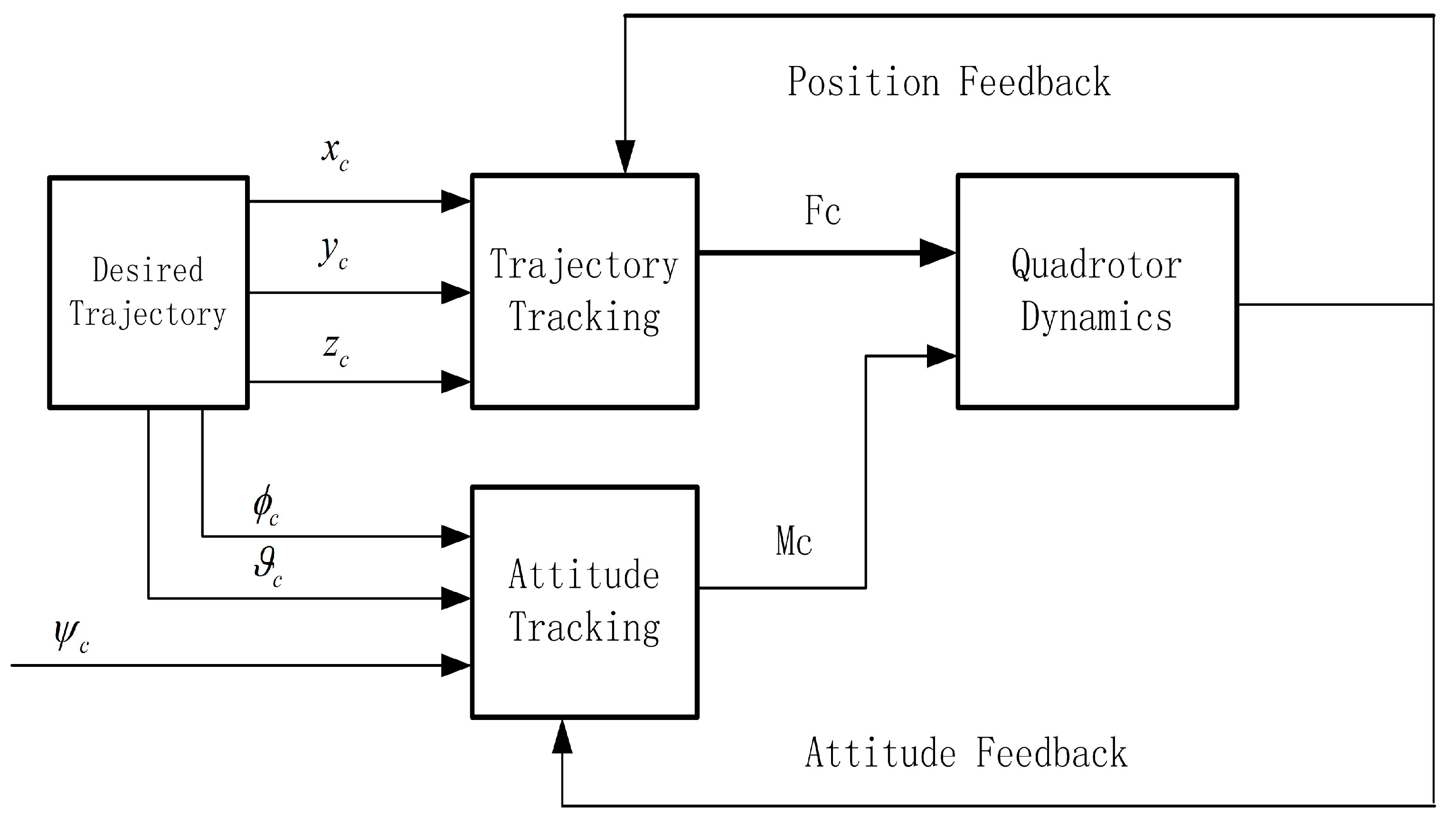
3. Modeling and Control Law Design

In this section, the detailed mathematical models of several reconfigurable quadrotors will be derived and then the corresponding control strategies are presented.

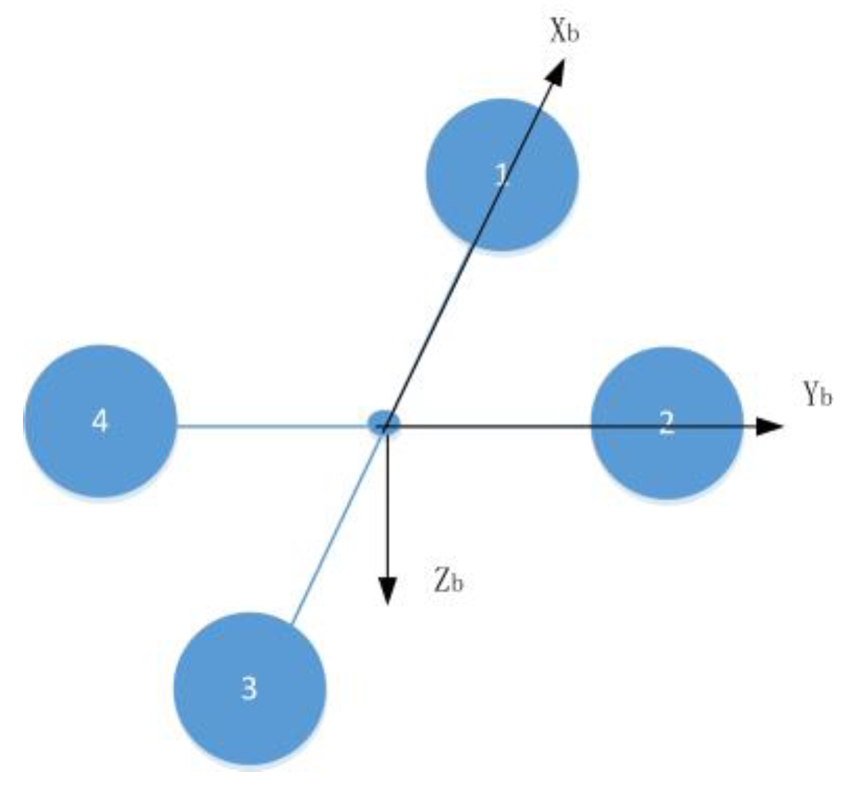
3.1. Kinematic Model and Dynamic Model

Based on the aforementioned assumptions, the initial or traditional configuration of quadrotors is depicted in Figure 1, the rotational configuration is depicted in Figure 2, the translational configuration is depicted in Figure 3, and the number in the center of the rotor is the serial number of rotors on the quadrotors. α is the deflection angle of anarm relative to its normal position in rotational reconfigurable mode, l 1 and l 2 are the distance from the rotor to the center of the normal quadrotor body in translational reconfigurable mode.
It can obviously be seen that there are several combinations of the above basic configurations. For the sake of brevity, here we present the mathematical model of a combination of rotational and translational configurations, and these reconfigurations are described in Figure 4, with the quadrotor body frame depicted in Figure 5.
For the sake of coherence, all the variables used here in this paper will be described. The original length of the arm is l , and during the reconfigurable process, its length varied with mission requirements and with a minimum value of l min 0 . The uniform linear density of each arm is ρ b , the vertical distance between the two arms or two layers is 2 d b , the mass of each rotor and motor is m , each reconfigurable exciting motor is m d , and the mass of the total payload is m p . In the original body frame, the center of the mass is at the origin of the body frame. According to corresponding calculations, it can be seen that the center of mass of the whole quadrotors does not change if and only if the symmetrical configuration can be held. Therefore, the mass center of the reconfiguration that is the result of only rotation is at the origin of the body frame, while the center of the combined reconfiguration will depend on four detailed positions of the rotors and motors.
The mathematical model of reconfiguration obviously can be classified into static and dynamic models; the static model is the model for which the reconfigurable process has been finished. Meanwhile, the dynamic model means that the reconfigurable process is ongoing, therefore the dynamic model has the characteristics of time variance and nonlinearity.
For the completeness of the mathematical model, the kinematic model and dynamic model of the pure translational reconfiguration and a simple combined reconfiguration are given below.

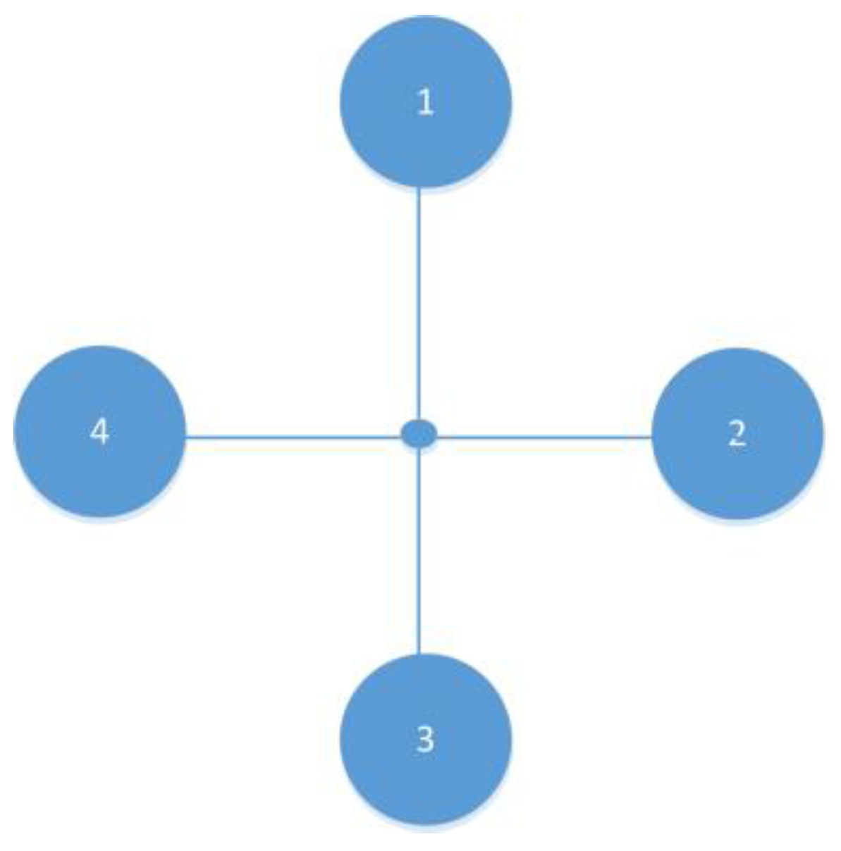
3.2. Model of Pure Translational Reconfiguration

We assume that the four driving motors are chosen to realize reconfiguration, each motor has a relative linear velocity of l ˙ i , i = 1 , 2 , 3 , 4 , so this scheme needs eight motors in total. Four motors are used to supply the necessary lift and moment, while the other four exciting motors are used to realize reconfiguration.
Here, the translational dynamics model is depicted as follows:
m e + 4 m u ˙ v ˙ w ˙ + ω × u v w = 0 0 μ 1 ( ω 1 2 + ω 2 2 + ω 3 2 + ω 4 2 ) + R e b 0 0 m e + 4 m g + F 1 m + F 3 m F 2 m + F 4 m 0 m l ¨ 1 + l ¨ 3 l ¨ 2 + l ¨ 4 0 m ω × l ˙ 1 + l ˙ 3 l ˙ 2 + l ˙ 4 0 + d F x d F y d F z m e = m d + m p
where u , v , w in the (1) are linear velocities of the center of mass of quadrotor body with respect to the inertial frame and expressed in the body frame; ω is the angular rate of the body frame with respect to the inertial frame as expressed in the body frame; ω i 2 is the square of the rotational rate of ith rotor; m e is the mass of payload and exciting motor; μ 1 is the coefficient of the aerodynamic lift of the rotor; g is the gravitational acceleration; R e b is the attitude transformation matrix which transform a vector in the earth frame to body frame; F i m is the locomotion force of the exciting motor; l ˙ i is the relative translational velocity of the ith rotor with respect to the body frame; l ¨ i is the relative translational acceleration of ith rotor with respect to the body frame; and d F i is the bounded disturbing forces.
The rotational dynamics model is depicted as follows:
J d ω d t + J ˙ ω + ω × J ω = μ 1 ( l 4 ω 4 2 l 2 ω 2 2 ) μ 1 ( l 1 ω 1 2 l 3 ω 3 2 ) μ 2 ( ω 1 2 ω 2 2 + ω 3 2 ω 4 2 ) + m g R e b l 2 l 4 l 3 l 1 0 + d M x d M y d M z
where μ 2 is the coefficient of the aerodynamic moment and d M i is the bounded disturbing moments. The inertia tensor and its derivative with respect to timeare describedin Equations (3) and (4).
J = m l 2 2 + l 4 2 + 1 3 ρ b l 2 3 + l 4 3 0 m l 1 + l 3 d b 0 m l 1 2 + l 3 2 + 1 3 ρ b l 1 3 + l 3 3 m l 2 + l 4 d b m l 1 + l 3 d b m l 2 + l 4 d b m b l 1 2 + l 2 2 + l 3 2 + l 4 2 + 1 3 ρ b l 1 3 + l 2 3 + l 3 3 + l 4 3
J ˙ = 2 m l ˙ 2 l 2 + l ˙ 4 l 4 + ρ b l ˙ 2 l 2 2 + l ˙ 4 l 4 2 0 m l ˙ 1 + l ˙ 3 d b 0 2 m l ˙ 1 l 1 + l ˙ 3 l 3 + ρ b l ˙ 1 l 1 2 + l ˙ 3 l 3 2 m l ˙ 2 + l ˙ 4 d b m l ˙ 1 + l ˙ 3 d b m l ˙ 2 + l ˙ 4 d b 2 m l ˙ 1 l 1 + l ˙ 2 l 2 + l ˙ 3 l 3 + l ˙ 4 l 4 + ρ b l ˙ 1 l 1 2 + l ˙ 2 l 2 2 + l ˙ 3 l 3 2 + l ˙ 4 l 4 2  
Corresponding to the dynamic model, the translational kinematic model is depicted as follows:
x ˙ y ˙ z ˙ = R b e u v w = c ϑ c ψ s ϕ s ϑ c ψ c ϕ s ψ c ϕ s ϑ c ψ + s ϕ s ψ c ϑ s ψ s ϕ s ϑ s ψ + c ϕ c ψ c ϕ s ϑ s ψ s ϕ c ψ s ϑ s ϕ c ϑ c ϕ c ϑ u v w
The rotational kinematic model is given below.
ϕ ˙ ϑ ˙ ψ ˙ = 1 sin ϕ tan ϑ cos ϕ tan ϑ 0 cos ϕ sin ϕ 0 sin ϕ cos ϑ cos ϕ cos ϑ p q r
where ϕ , ϑ , ψ are the attitude angles of the quadrotors.
Based on the above mathematical model, and the given initial value of the state and desired locomotion force, the dynamic reconfigurable procedure can be determined through solving a set of ordinary differential equations using traditional Runge–Kutta methods.
It should be noted that although this kind of reconfiguration has eight actuators in summation, the whole system is still an underactuated one.

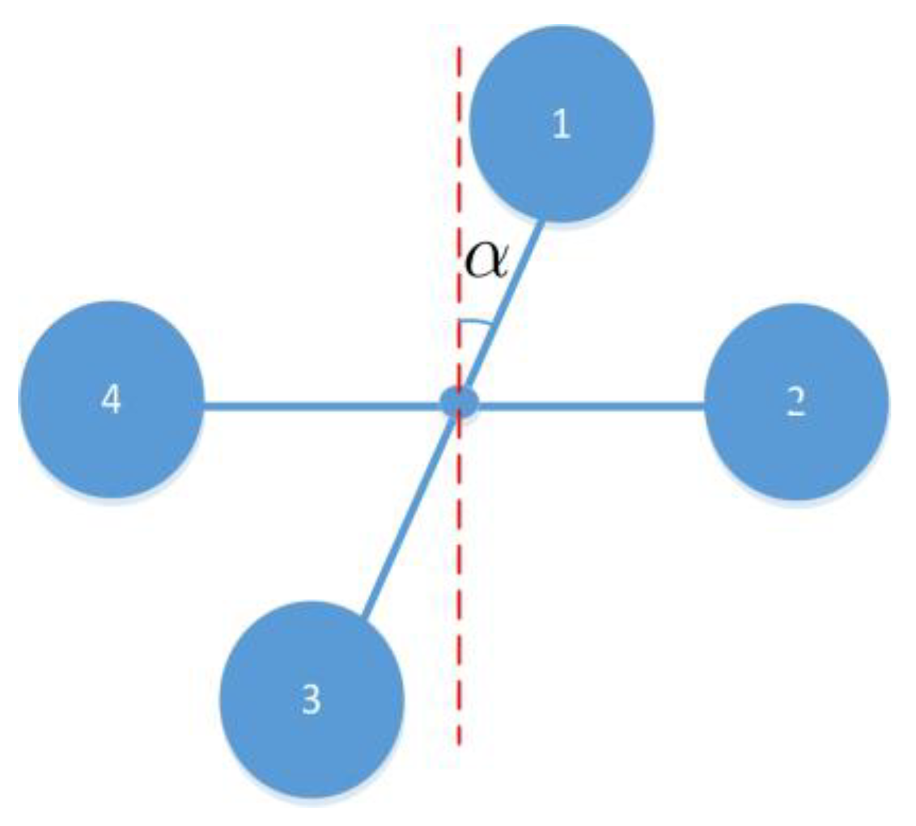
3.3. Model of Pure Rotational Reconfiguration

In this section, a different reconfiguration which was deduced from only a rotational exciter is presented.
In this configuration, we assume that the rotation rate of one arm relative to another one is α ˙ , the bounded disturbing forces are d F i . For the sake of simplification, the translational dynamics of this configuration are given directly below.
m e + 4 m u ˙ v ˙ w ˙ + ω × u v w = 0 0 μ 1 ω 1 2 + ω 2 2 + ω 3 2 + ω 4 2 + R e b 0 0 m e + 4 m g + d F x d F y d F z ω = p , q , r T
The rotational dynamics of this configuration is depicted as follows:
J d ω d t + J ˙ ω + ω × J ω = μ 1 l ω 4 2 ω 2 2 + μ 1 l ω 1 2 ω 3 2 sin α μ 1 l ω 3 2 ω 1 2 cos α μ 2 ω 1 2 ω 2 2 + ω 3 2 ω 4 2 + 0 0 M α + d M x d M y d M z
The bounded disturbing moments acted on the body of quadrotors is depicted as d M i .
The detailed inertia matrix and its derivative with respect to time are depicted as follows:
J = 2 m l 2 1 + sin 2 α + 2 3 ρ b l 3 1 + sin 2 α 2 m l 2 cos α sin α + 2 3 ρ b l 3 cos α sin α 0 2 m l 2 cos α sin α + 2 3 ρ b l 3 cos α sin α 2 m l 2 cos 2 α + 2 3 ρ b l 3 cos 2 α 0 0 0 4 m l 2 + 4 3 ρ b l 3 J ˙ = 2 l 2 α ˙ m + ρ b l 3 sin 2 α 2 l 2 α ˙ m + ρ b l 3 cos 2 α 0 2 l 2 α ˙ m + ρ b l 3 cos 2 α 2 l 2 α ˙ m + ρ b l 3 sin 2 α 0 0 0 0
where M α is the active moment exerting on arms 1–3 by the exciting motor.
It should be noted that this configuration is deduced from the traditional configuration only by one arm rotating relative to another arm.
No matter how the dynamics models vary, the kinematic model in this configuration is the same as that described in Equations (5) and (6).

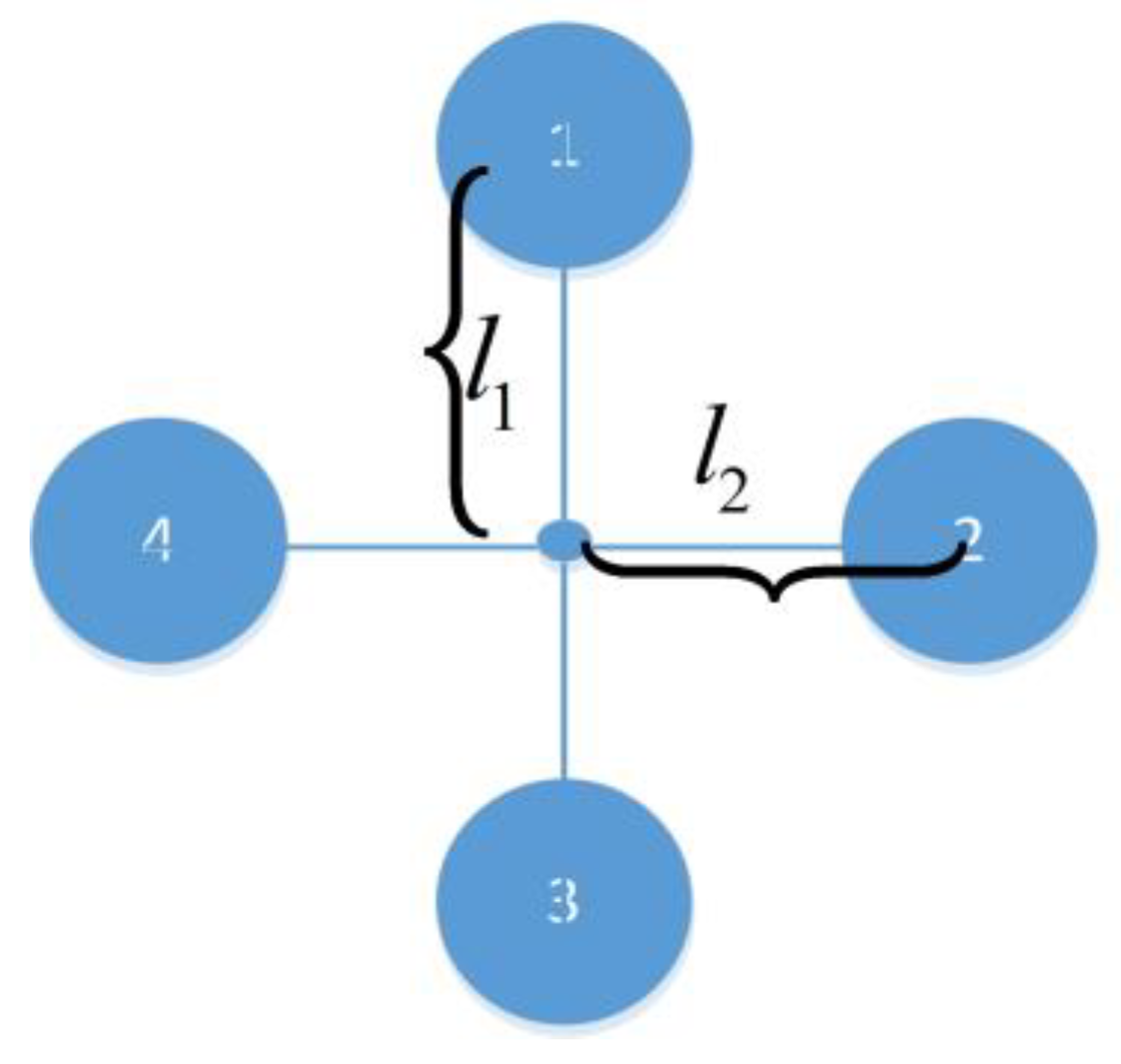
3.4. Model of Translational Plus Rotational Reconfiguration

In this reconfiguration model, the translational movement of rotors and the rotational movements of rotors are simultaneously taken into consideration. In this scenario, the center of mass of the whole system changes with time; meanwhile, the inertia of the system around the center of the mass also varies with configuration. It is clear that this kind of configuration is complicated and is difficult to control because of the strong nonlinearity, coupling effects, and time variant character.
Inspired by the work of [14], we give the calculation formula of the center of mass and inertia of the whole system below.
r U A V = i = 1 4 m i r i + i = 1 4 m a r m i r a r m i m U A V
where m U A V is the total mass of the UAV system; m i is the mass of the ith rotor and connected motor; m a r m i is the mass of the ith arm of the UAV system; r i is the displacement vector of the ith rotor in the normal initialized body frame; and r a r m i is the displacement vector of the ith arm in the normal initialized body frame. When the real center of mass of the UAV configuration has been calculated, the inertia moment of the UAV configuration based on the new center of mass can be calculated using parallel axis theorem as described in reference [14].
For the convenience of the simulation, the corresponding relationship of lift and moment with rotor speed is given below.
ω 1 2 ω 2 2 ω 3 2 ω 4 2 = l 3 2 μ 1 ( l 1 + l 3 ) 0 1 μ 1 ( l 1 + l 3 ) cos α l 3 2 μ 2 ( l 1 + l 3 ) l 4 2 μ 1 ( l 2 + l 4 ) 1 μ 1 ( l 2 + l 4 ) sin α μ 1 ( l 2 + l 4 ) cos α l 4 2 μ 2 ( l 2 + l 4 ) l 1 2 μ 1 ( l 1 + l 3 ) 0 1 μ 1 ( l 1 + l 3 ) cos α l 1 2 μ 2 ( l 1 + l 3 ) l 2 2 μ 1 ( l 2 + l 4 ) 1 μ 1 ( l 2 + l 4 ) sin α μ 1 ( l 2 + l 4 ) cos α l 2 2 μ 2 ( l 2 + l 4 ) F M x M y M z
where F is the lift and M i , i = x , y , z is the moment acting on the quadrotor body; this equation is the so-called control matrix.
In this paper, the parameters of the researched UAV system are given in Table 1.
Remark 1.
The command signals in this paper include position command signal, velocity commands, linear acceleration commands, attitude commands, angular rate commands, and angular acceleration commands. All these commands are generated through a command signal generator, the generated procedure is omitted herein for the sake of brevity, the detailed formulations will be given in the simulation section. The detailed design procedure of command signals can be found in reference [3,13] and the explicit command pitch angle and command roll angle can be found in Equation (29), and the command yaw angle can be found in Equation (30).

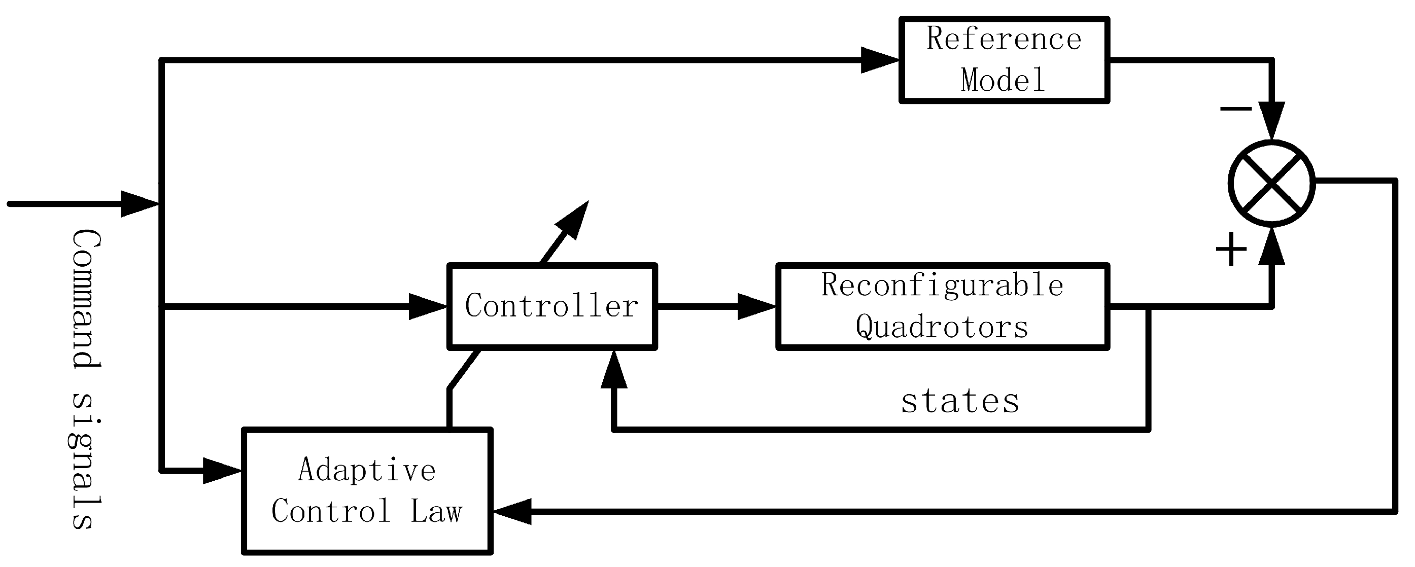
3.5. Model Reference Adaptive Control Law Design

Because of the complexity of the plant itself and the uncertainties of the environmental disturbances, we chose the model reference adaptive control as the method for designing the body rate tracking controllers. It should be noted that the translational controllers are designed using a proportional–integral–differential method.
The complete control block diagram was expressed in Figure 6.
Inspired by references [29,30], the aforementioned models of the reconfigurable quadrotors can be depicted as follows:
x ˙ p = A p x p + B p u p x p = p , q , r T
The reference model is depicted as follows:
x ˙ m = A m x m + B m r c m d
Figure 6 reveals the idea of the model reference adaptive control, so in Equations (12) and (13), there are control inputs for the plant and command signal for the reference model. It should be noted that the systematic matrix and control matrix in Equations (12) and (13) all have reasonable dimensions.
For the sake of conveniently using the MRAC to design the body rate tracking law and attitude tracking law, the original dynamical Equations (2) and (8) are rewritten as follows:
ω ˙ = A α , l , α ˙ , l ˙ ω + C α , l M c m d + B α , l f ω + C α , l d A α , l , α ˙ , l ˙ = J α , l 1 J ˙ α , l , α ˙ , l ˙ B α , l f ω = J α , l 1 ω × J α , l ω C α , l = J α , l 1
where d is external disturbances and M c m d is the command moment.
In order to conveniently derive the control laws, we define
e ( t ) = x p ( t ) x m ( t )
It should be noted that x p ( t ) and x m ( t ) are not consistent with the detailed translational or rotational movement variables. We suppose that the control input is inthe following form:
u ( t ) = Θ x ( t ) x p ( t ) + Θ r ( t ) r c m d ( t )
Then, we can obtain
x ˙ p ( t ) = A p + B p Θ x ( t ) x p ( t ) + B p Θ r ( t ) r c m d ( t )
Up to now, because of the identity of Equations (11) and (14), we can obtain the desired gain matrices depicted as follows.
A p + B p Θ x ( t ) = A m Θ x ( t ) = B p T B p 1 B p T A m A p B p Θ r ( t ) = B m Θ r ( t ) = B p T B p 1 B p T B m
As expressed in Equation (17), we consider the non-square matrix formulations of the control matrix of the plant; meanwhile, the error between the real state of the plant and the state from the reference model vary with time, so we define the error of the gain matrices as follows:
Θ ˜ x ( t ) = Θ x ( t ) Θ x ( t ) Θ ˜ r ( t ) = Θ r ( t ) Θ r ( t )
Based on the above descriptions, in order to evaluate the convergence of the state error, we choose the Lyapunov function as follows:
V e ( t ) , Θ ˜ x ( t ) , Θ ˜ r ( t ) = 1 2 e T ( t ) P e ( t ) + T r Θ ˜ x T ( t ) Γ x Θ ˜ x ( t ) + T r Θ ˜ r T ( t ) Γ r Θ ˜ r ( t )
All the weight matrices in Equation (20) are supposed to be symmetric and positive definite.
According to Equation (20), we obtain
V ˙ e ( t ) , Θ ˜ x ( t ) , Θ ˜ r ( t ) = 1 2 e ˙ T ( t ) P e ( t ) + e T ( t ) P e ˙ ( t ) + 1 2 T r Θ ˜ ˙ x T ( t ) Γ x Θ ˜ x ( t ) + Θ ˜ x T ( t ) Γ x Θ ˜ ˙ x ( t ) + 1 2 T r Θ ˜ ˙ r T ( t ) Γ r Θ ˜ r ( t ) + Θ ˜ r T ( t ) Γ r Θ ˜ ˙ r ( t )
According to Equation (13), we have
e ˙ ( t ) = A m e ( t ) + A p + B p Θ x ( t ) A m x p ( t ) + B p Θ r ( t ) B m r c m d ( t )
Substituting Equation (22) into Equation (21), we have
V ˙ e ( t ) , Θ ˜ x ( t ) , Θ ˜ r ( t ) = 1 2 e T ( t ) A m T P + P A m e ( t ) + 1 2 x p T ( t ) Θ ˜ x T ( t ) B p T P e ( t ) + e T ( t ) P B p Θ ˜ x ( t ) x p ( t ) + 1 2 r T ( t ) Θ ˜ r T ( t ) B p T P e ( t ) + e T ( t ) P B p Θ ˜ r ( t ) r ( t ) + 1 2 T r Θ ˜ ˙ x T ( t ) Γ x Θ ˜ x ( t ) + Θ ˜ x T ( t ) Γ x Θ ˜ ˙ x ( t ) + 1 2 T r Θ ˜ ˙ r T ( t ) Γ r Θ ˜ r ( t ) + Θ ˜ r T ( t ) Γ r Θ ˜ ˙ r ( t )
According to Equation (23), if the following equations are valid,
A m T P + P A m = Q Θ ˙ x = Γ x 1 e T ( t ) P B p x p ( t ) Θ ˙ r = Γ r 1 e T ( t ) P B p r ( t )
Then, the semi-negative definiteness of the derivative of the Lyapunov function can be assured.
V ˙ e ( t ) , Θ ˜ x ( t ) , Θ ˜ r ( t ) = e T ( t ) Q e ( t ) 0
Meanwhile, the gain matrices of the adaptive control strategy can be derived from Equation (23). Equations (11)–(25) are general formula to derive the adaptive control laws, in the preceding simulation, especially the body rate tracking section, the reference adaptive control laws will be derived based on the following description.
The candidate Lyapunov function is chosen as follows:
V = 1 2 e T P e + 1 2 T r Θ ˜ x T Γ 1 1 Θ ˜ x + 1 2 T r Θ ˜ r T Γ 2 1 Θ ˜ r + 1 2 T r Θ ˜ f T Γ 3 1 Θ ˜ f + 1 2 T r Θ ˜ d T Γ 4 1 Θ ˜ d
Here, the external disturbance and systematic error are considered, based on this candidate Lyapunov function, the gain matrices differential equations can be obtained as follows:
Θ ˜ ˙ x = Γ 1 C p T P e x p T Θ ˜ ˙ r = Γ 2 C p T P e r c T Θ ˜ ˙ f = Γ 3 C p T P e f T x p Θ ˜ ˙ d = Γ 4 C p T P e d T
where Γ i ,   i = 1 , 2 , 3 , 4 denotes the positive and symmetric constant matrix.
The block diagram of motion control for the reconfigurable quadrotors is depicted in Figure 7; the quadrotor dynamics block indeed includes both the kinematics and dynamics of the quadrotors in simulation. The MRAC laws proposed in this paper are realized in the attitude tracking block.
From the point of view of the control and information processing, the detailed simulation flow chart based on MRAC is given in Figure 8. In the initialization section, the waypoints and corresponding velocities, accelerations, and even jerk and snap should be determined, flight duration should also be given to calculate the desired trajectory iteratively. For the sake of verifying the control laws, the time duration of reconfiguration based on normal configuration is less than 1 s. Based on this assumption, the detailed center of mass of the quadrotors can be calculated and the corresponding inertia of the body can be determined. In the simulation procedure, the position, attitude, and velocity of the quadrotors can be fed back to the control law design modular, this is consistent with the practical flight conditions because of the use of MEMS IMU and other onboard sensors, such as barometers and magnetometers. These sensors can be integrated to provide flight data simultaneously.
The detailed procedure of the desired trajectory calculation is omitted here for the sake of brevity; however, interested readers can be referred to associated references.
Here, we deliberately describe the logical relationship behind Figure 7 and Figure 8. Figure 7 shows the input signals and output signals of the quadrotors, and Figure 8 describes the whole simulation process for the quadrotors. In fact, the core is the generation of control signals and the logical relationship between inputs and outputs.Excited by the input signals, the quadrotor firstly outputs linear acceleration and angular acceleration, then linear velocity and angular velocity, and finally outputs position and attitude.

4. Simulation and Analysis

4.1. Initialization of Simulation

In order to evaluate the proposed adaptive control method, in this section, the detailed value of parameters associated with non-reconfiguration will be given in Table 2, and the varying inertia values associated with reconfiguration will be calculated based on aforementioned formulas. Apart from the initial values of the inertia, the initial position, velocity, and attitude of the quadrotors will also be given in this section.
In addition to the above parameters and initial conditions, the command signals to be tracked should be given in the following sections. Because the different scenarios have different tracking parameters, the detailed command signals herein only describe the translational command signals, associated roll angle command signal, and pitch angle command signal which are derived from the translational constraints.
It should also be noted that the command trajectory is designed based on the predefined waypoints and its corresponding initial velocities and accelerations, and jerk and snap can also be obtained through the time polynomials of the command trajectory.
Meanwhile, the reference model in Figure 6 is given below.
x ˙ m = p ˙ q ˙ r ˙ m = d i a g 1 T p , 1 T q , 1 T r ( p q r m p q r c m d ) x ˙ m = A m x m + B m r c m d
where the subscript m means the measured value of reference model; subscript cmd means the command value; and T j , j = p , q , r is the chosen time constant of the plant.
For the sake of completeness, the formula of the conversion from desired trajectory to command attitude is given below.
ϑ c = a t a n x ¨ c cos ψ c + y ¨ c sin ψ c z ¨ c + g ϕ c = a t a n x ¨ c sin ψ c y ¨ c cos ψ c z ¨ c + g 2 + x ¨ c cos ψ c + y ¨ c sin ψ c 2
where ψ c is designed independently and in advance and x ¨ c , y ¨ c and z ¨ c are the acceleration of the desired trajectory. Equation (30) is the formula of the command yaw angle, where ψ ( t 0 ) , ψ ˙ ( t 0 ) , and ψ ¨ ( t 0 ) are the initial values of the yaw angle, the initial velocity of the yaw angle, and the initial acceleration of the yaw angle, respectively. Correspondingly, ψ ( t f ) , ψ ˙ ( t f ) , and ψ ¨ ( t f ) are the final values of the yaw angle, the final velocity of the yaw angle, and the final acceleration of the yaw angle, respectively.
ψ c ( t ) = ψ ( t 0 ) + ψ ˙ ( t 0 ) ( t t 0 ) + ψ ¨ ( t 0 ) 2 ( t t 0 ) 2 + 10 ψ ( t f ) ψ ( t 0 ) ( t f t 0 ) 3 6 ψ ˙ ( t 0 ) + 4 ψ ˙ ( t f ) ( t f t 0 ) 2 + ψ ¨ ( t f ) 3 ψ ¨ ( t 0 ) 2 ( t f t 0 ) ( t t 0 ) 3 + 15 ψ ( t 0 ) ψ ( t f ) ( t f t 0 ) 4 + 8 ψ ˙ ( t 0 ) + 7 ψ ˙ ( t f ) ( t f t 0 ) 3 + 3 ψ ¨ ( t 0 ) 2 ψ ¨ ( t f ) 2 ( t f t 0 ) 2 ( t t 0 ) 4 + 6 ψ ( t f ) ψ ( t 0 ) ( t f t 0 ) 5 3 ψ ˙ ( t 0 ) + ψ ˙ ( t f ) ( t f t 0 ) 4 + ψ ¨ ( t f ) ψ ¨ ( t 0 ) 2 ( t f t 0 ) 3 ( t t 0 ) 5
It should be noted that in the simulation section and practical applications, all the command signals are followed by a low-pass filter and limiter for the sake of compromise considerations, because the settling time is closely related with the bandwidth and maximum power of actuators.
Associated parameters in this section are given below.
T p = T q = T r = 0.006 k p ϕ = k p ϑ = k p ψ = 1.0 k i ϕ = k i ϑ = k i ψ = 0.5 Γ 1 = 10 9 8 9 10 7 8 7 10 Γ 2 = 12 9 8 9 12 7 8 7 12 Γ 3 = 12 8 7 8 12 6 7 6 12 Γ 4 = 11 8 7 8 11 6 7 6 11
where Γ i , i = 1 , 2 , 3 , 4 are the chosen parameters to calculate the desired control gains and k s t , s = i , p ; t = ϕ , ϑ , ψ are attitude control gains.
It should be noted that only the body rate command signal is presented, because of the under-actuated characteristics, the linear motion control should be achieved through angular motion control, so the detailed position command signals and velocity command signals are all omitted here.
The detailed mathematical simulation architecture is constructed based on MATLAB/Simulink and the whole simulation frame includes three blocks, the first block simulates the command signals and external disturbances, the second block simulates the detailed mathematical models, and cases with sensor errors and without sensor errors are all taken into consideration. The third block constructs the adaptive control laws.
In the simulation procedure, in order to evaluate the control laws equally, the sensor errors added to the measured signals are zero mean value Gaussian white noise with standard deviation one. All the external disturbances acting on the quadrotors are chosen as band-limited white noise added with sinusoid whose amplitude is less than 0.5, the performance of the control law can be obviously distinguished through the desired actuator power and control gain.

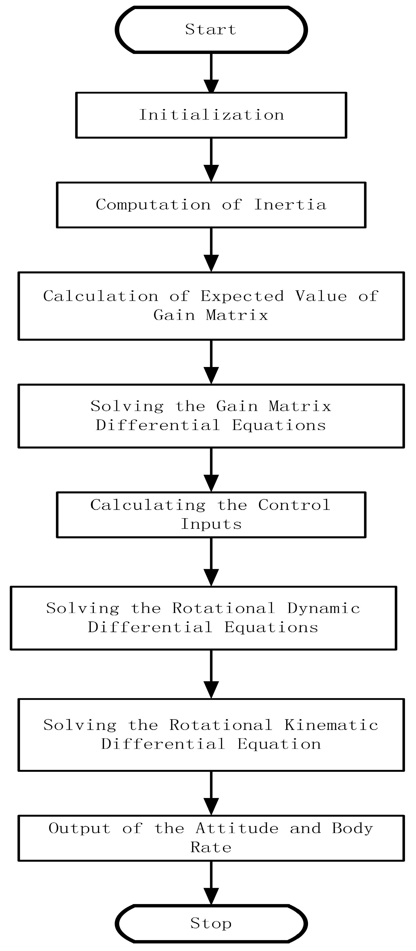
4.2. Simulation Based on MRAC

Herein the reconfigurable quadrotors mean the four rotors can translate or rotate relative to the body frame, so the adaptive control law will be applied to translational reconfiguration and rotational reconfiguration.
The simulation scenario depicted in this section are used for verifying the feasibility of the MRAC; we assume that translational reconfiguration and rotational reconfiguration take place simultaneously within 1.5 s, the translate velocity of the rotor is less than 0.05 m/s, the rotational velocity of rotor is less than 0.1 rad/s, the translate acceleration of the rotor is less than 0.02 m/s2, and the rotational acceleration is less than 0.01 rad/s2. The trajectory is smooth and with initial position of (0 m, 0 m, 0 m) and final position of (5 m, 5 m, 4 m) in the Earth frame, the corresponding initial attitude, initial linear velocity, angular velocity, initial linear acceleration and angular acceleration, and final value of these parameters are omitted here; meanwhile, the final conditions are also omitted. The flight duration is 1–15 s, the external force disturbance and external moment disturbances are chosen as the constant value plus stochastic terms, extensive simulations have been conducted, the absolute value of external force is less than 1 N, and the absolute value of the external moment is less than 0.5 Nm, within only partial simulation results of translational reconfiguration plus rotational reconfiguration which are shown in the following section.
It can be seen that the final yaw angle is nearly 0.80 radian, this value is nearly the desired final yaw angle and the position error is less than 5 cm. The upper limit of the rotor is 900 rad/s. In order to clearly visualize the attitude command signals and simulated attitude signals, the roll angle, pitch angle, and yaw angle and their corresponding command signals are shown in the diagrams in Figure 9, Figure 10 and Figure 11, respectively. Furthermore, the desired position signals and simulated position signals are shown in Figure 12, Figure 13 and Figure 14. Figure 15 shows the history of the body rate and lift force varying with time, the rotating velocity of every rotor of quadrotors is shown in Figure 16, and all these results show that flight parameters of reconfigurable quadrotors are within the reasonable range.
The adaptive matrix gains vary with time, and are shown in Figure 17, Figure 18, Figure 19, Figure 20, Figure 21 and Figure 22.
Where Θ R is the reference signal feedback gain and Θ X is the state feedback gain, it can be seen that the main elements are all the diagonal ones and this is consistent with the design procedure.
It should be noted that the simulation results of Θ f and Θ d varying with time are omitted for the sake of brevity.
Although only partial flight parameters are visualized, the similarity of the associated flight parameters can be guaranteed and the online calculation of ordinary differential equations can be realized through simplified algorithms, such as the Euler explicit method can be used to replace the traditional Runge–Kutta method.

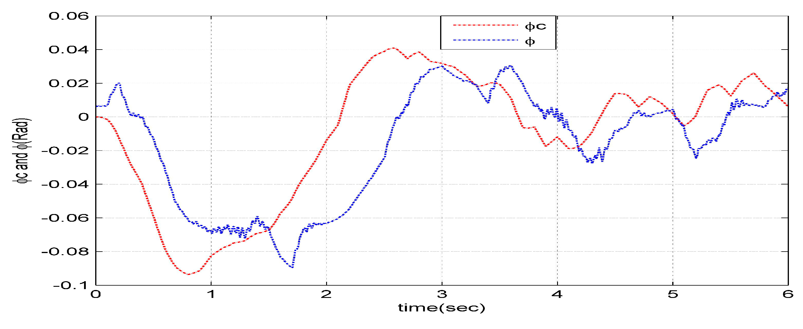
4.3. Simulation Result

Table 3 shows the qualitative results of the simulations described in this section, where the second column is the maximum of the flight parameters, such as attitude error and position error, while the third column is the chosen time constant of the reference model, the fourth column is the value range of external forces, and the fifth column is the value range of the external moments. Under the interference of these disturbances, the position errors and attitude errors depicted in the first column are within the reasonable scope.
Based on numerous conducted simulations, the simulation results can be drawn as follows: (1) given the same initial conditions and final conditions, the position errors and attitude errors from the MARC are within the error budget; (2) the MRAC control laws can be implemented onboard at the cost of more computational burden; (3) the choice of time constant of reference model is very important to determine the completeness of the simulation; (4) the time delay of the control vectors is a key factor to be chosen; in this paper, this value should be less than 7 ms, and otherwise the simulation result will diverge rapidly; and (5) MRAC control law has good dynamic performance and strong robustness when the quadrotors are excited by external disturbances. These external disturbances include a constant part and a random part.

5. Conclusions

In view of the challenging missions in complicated scenarios, the mathematical model of translational reconfiguration and rotational reconfiguration of traditional quadrotors was proposed in this paper, associated with assumptions about reconfigurable quadrotors. Then, the control laws were designed using the model reference adaptive control method based on Lyapunov stability theory, while a simulation was performed through numerical calculation. The simulation results verify the feasibility of the proposed control laws when it is used for body rate tracking and reveal the important effect of time delay of control inputs on the stability of the motion control system. Meanwhile, the dependence of stability of motion control on the time constant of reference system was explicitly revealed; according to our simulation results, this value should be less than 7 milliseconds, otherwise the attitude tracking error and position tracking error will diverge. From a practical point of view, the design idea of translational reconfigurable quadrotors and rotational reconfigurable quadrotors is feasible, and the body rate tracking control method based on MRAC is applicable.
In the future, the sensitivity analysis of translational velocity, rotational velocity, translational acceleration, and rotational acceleration on the performance of motion control should be performed, and this is the foundation when the proposed control laws are applied to the practical engineering. Furthermore, the numerical integral algorithm used for solving the matrix gain ordinary differential equations should also be intensively researched. In addition to the aforementioned future research contents and directions, reconfiguration ideas can be applied to tilting rotor UAVs, fully actuated quadrotors, over-actuated quadrotors, and other types of robots. At the same time, MRAC can also be extended to attitude tracking and position tracking.

Author Contributions

Conceptualization, Z.L. and G.C.; methodology, Z.L.; software, G.C. and S.X.; validation, Z.L., G.C. and S.X.; formal analysis, Z.L. and G.C.; investigation, G.C.; resources, Z.L.; data curation, G.C.; writing—original draft preparation, Z.L.; writing—review and editing, Z.L. and G.C.; visualization, G.C. and S.X.; project administration, Z.L.; funding acquisition, Z.L. All authors have read and agreed to the published version of the manuscript.

Funding

This research was funded by the key projects of the Shaanxi Provincial Department of Science and Technology (Grant No. 2022GY-239).

Data Availability Statement

All data used during the study appear in the submitted article.

Conflicts of Interest

All the authors declare that they have no known competing financial interestsor personal relationships that could appear to influence the work reported in this paper.

References

  1. Bangura, M.; Hou, X.; Allibert, G.; Mahony, R.; Michael, N. Supervisory Control of Multirotor Vehicles in Challenging Conditions Using Inertial Measurements. IEEE Trans. Robot. 2018, 34, 1490–1501. [Google Scholar] [CrossRef]
  2. Bauersfeld, L.; Spannagl, L.; Ducard, G.; Onder, C. MPC Flight Control for a Tilt-Rotor VTOL Aircraft. IEEE Trans. Aerosp. Electron. Syst. 2021, 57, 2395–2409. [Google Scholar] [CrossRef]
  3. Borkar, A.V.; Hangal, S.; Arya, H.; Sinha, A.; Vachhani, L. Reconfigurable Formations of Quadrotors on Lissajous Curves for Surveillance Applications. Eur. J. Control 2020, 56, 274–288. [Google Scholar] [CrossRef]
  4. Bucki, N.; Mueller, M.W. Design and Control of a Passively Morphing Quadcopter. In Proceedings of the 2019 IEEE International Conference on Robotics and Automation, Montreal, QC, Canada, 20–24 May 2019. [Google Scholar]
  5. D’Sa, R.R. Design of a Transformable Unmanned Aerial Vehicle. Ph.D. Thesis, University of Minnesota, Minneapolis, MN, USA, 2020. [Google Scholar]
  6. Chen, Y.; Wang, Z.; Lyu, Z.; Li, J.; Yang, Y.; Li, Y. Research on Manipulation Strategy and Flight Test of the Quad Tilt Rotor in Conversion Process. IEEE Access 2021, 9, 40286–40307. [Google Scholar] [CrossRef]
  7. Craig, W.; Yeo, D.; Paley, D.A. Geometric Attitude and Position Control of a Quadrotor in Wind. J. Guid. Control Dyn. 2020, 43, 870–883. [Google Scholar] [CrossRef]
  8. Dehkordi, M.D.; Danesh, M. Positionable Rotor Quadrotor: Dynamic Modeling and Adaptive Finite-Time Sliding-Mode Controller Design. J. Guid. Control Dyn. 2022, 45, 424–433. [Google Scholar] [CrossRef]
  9. Ding, C.; Lu, L. A Tilting-Rotor Unmanned Aerial Vehicle for Enhanced Aerial Locomotion and Manipulation Capabilities: Design, Control, and Applications. IEEE/ASME Trans. Mechatron. 2021, 26, 2237–2248. [Google Scholar] [CrossRef]
  10. Falanga, D.; Kleber, K.; Mintchev, S.; Floreano, D.; Scaramuzza, D. The Foldable Drone: A Morphing Quadrotor that Can Squeeze and Fly. IEEE Robot. Autom. Lett. 2019, 4, 209–216. [Google Scholar] [CrossRef]
  11. Gandhi, N.; Saldana, D.; Kumar, V.; Phan, L.T.X. Self-Reconfiguration in Response to Faults in Modular Aerial Systems. IEEE Robot. Autom. Lett. 2020, 5, 2522–2529. [Google Scholar] [CrossRef]
  12. Hess, R.A.; Wells, S.R. Sliding Mode Control Applied to Reconfigurable Flight Control Design. J. Guid. Control Dyn. 2003, 26, 452–462. [Google Scholar] [CrossRef]
  13. Cutler, M.J. Design and Control of an Autonomous Variable-Pitch Quadrotor Helicopter. Master’s Thesis, Massachusetts Institute of Technology, Cambridge, MA, USA, 2012. [Google Scholar]
  14. Hu, D.; Pei, Z.; Shi, J.; Tang, Z. Design, Modeling and Control of a Novel Morphing Quadrotor. IEEE Robot. Autom. Lett. 2021, 6, 8013–8020. [Google Scholar] [CrossRef]
  15. Kulkarni, M.; Nguyen, H.; Alexis, K. The Reconfigurable Aerial Robotic Chain: Shape and Motion Planning. IFAC-PapersOnLine 2020, 53, 9295–9302. [Google Scholar] [CrossRef]
  16. Li, B.; Ma, L.; Wang, D.; Sun, Y. Driving and Tilt-Hovering—An Agile and Maneuverable Aerial Vehicle with Tiltable rotors. IET Cyber-Syst. Robot. 2021, 3, 103–115. [Google Scholar] [CrossRef]
  17. Mofid, O.; Mobayen, S. Adaptive Sliding Mode Control for Finite-Time Stability of Quad-Rotor UAVs with Parametric Uncertainties. ISA Trans. 2018, 72, 1–14. [Google Scholar] [CrossRef] [PubMed]
  18. Marques, F.M.M.; de Assis, P.A.Q.; Neto, R.M.F. Position Tracking of a Tilt-Rotor Quad-copter with Small Attitude Variation Using Model Predictive Control. In Proceedings of the AIAA Aviation Forum, Virtual Event, 15–19 June 2020. [Google Scholar]
  19. Niemiec, R.; Gandhi, F.; Singh, R. Control and Performance of a Reconfigurable Multicopter. J. Aircr. 2018, 55, 1855–1866. [Google Scholar] [CrossRef]
  20. Outeiro, P.; Cardeira, C.; Oliveira, P. Multiple-Model Adaptive Control Architecture for a Quadrotor with Constant Unknown Mass and Inertia. Aerosp. Sci. Technol. 2021, 117, 106899–106912. [Google Scholar] [CrossRef]
  21. Pose, C.D.; Giribet, J.I.; Mas, I. Fault Tolerance Analysis for a Class of Reconfigurable Aerial Hexarotor Vehicles. IEEE/ASME Trans. Mechatron. 2020, 25, 1851–1858. [Google Scholar] [CrossRef]
  22. Seo, J.; Paik, J.; Yim, M.; Robotics, M.R. Annual Review of Control. Robot. Auton. Syst. 2019, 2, 63–88. [Google Scholar] [CrossRef]
  23. Wang, N.; Deng, Q.; Xie, G.; Pan, X. Hybrid Finite-Time Trajectory Tracking Control of a Quadrotor. ISA Trans. 2019, 90, 278–286. [Google Scholar] [CrossRef]
  24. Yang, D.; Li, Z.; Zhou, P.; Lu, J. Control System Design for Tiltable Quad-rotor with Propeller Failure. In Proceedings of the 2020 Chinese Automation Congress, Shanghai, China, 6–8 November 2020; pp. 7473–7478. [Google Scholar]
  25. Zhang, S. Development of Unconventional Unmanned Aerial Vehicle with Tilt-Rotor Platform. Ph.D. Thesis, National University of Singapore, Singapore, 2018. [Google Scholar]
  26. Zhao, N.; Luo, Y.; Deng, H.; Shen, Y. The deformable quad-rotor: Design, Kinematics and Dynamics Characterization, and Flight Performance Validation. In Proceedings of the 2017 IEEE/RSJ International Conference on Intelligent Robots and Systems, Vancouver, BC, Canada, 24–28 September 2017. [Google Scholar]
  27. Zheng, P.; Tan, X.; Kocer, B.B.; Yang, E.; Kovac, M. TiltDrone: A Fully-Actuated Tilting Quadrotor Platform. IEEE Robot. Autom. Lett. 2020, 5, 6845–6852. [Google Scholar] [CrossRef]
  28. Lee, J.; Lee, D.; Kim, J.; Kim, D.; Jang, I.; Kim, H.J. Fully Actuated Autonomous Flight of Thruster-Tilting Multirotor. IEEE/ASME Trans. Mechatron. 2021, 26, 765–776. [Google Scholar] [CrossRef]
  29. Anaswamy, A.M. Adaptive Control and Intersections with Reinforcement Learning. Annu. Rev. Control Robot. Auton. Syst. 2023, 6, 65–93. [Google Scholar] [CrossRef]
  30. Dydek, Z.T. Adaptive Control of Unmanned Aerial Systems. Ph.D. Thesis, Massachusetts Institute of Technology, Cambridge, MA, USA, 2010. [Google Scholar]
Figure 1. Traditional configuration.
Aerospace 11 00687 g001
Figure 2. Rotational configuration.
Aerospace 11 00687 g002
Figure 3. Translational configuration.
Aerospace 11 00687 g003
Figure 4. Combined configuration.
Aerospace 11 00687 g004
Figure 5. Body frame.
Aerospace 11 00687 g005
Figure 6. Adaptive control block.
Aerospace 11 00687 g006
Figure 7. Block diagram of motion control.
Aerospace 11 00687 g007
Figure 8. Simulation flow chart based on MRAC.
Aerospace 11 00687 g008
Figure 9. ϕ c   and   ϕ .
Aerospace 11 00687 g009
Figure 10. θ c   and   θ .
Aerospace 11 00687 g010
Figure 11. ψ c   and   ψ .
Aerospace 11 00687 g011
Figure 12. X c   and   X .
Aerospace 11 00687 g012
Figure 13. Y c   and   Y .
Aerospace 11 00687 g013
Figure 14. Z c   and   Z .
Aerospace 11 00687 g014
Figure 15. Body rate and lift.
Aerospace 11 00687 g015
Figure 16. Speed of rotor.
Aerospace 11 00687 g016
Figure 17. First column of Θ R .
Aerospace 11 00687 g017
Figure 18. Second column of Θ R .
Aerospace 11 00687 g018
Figure 19. Third column of Θ R .
Aerospace 11 00687 g019
Figure 20. First column of Θ X .
Aerospace 11 00687 g020
Figure 21. Second column of Θ X .
Aerospace 11 00687 g021
Figure 22. Third column of Θ X .
Aerospace 11 00687 g022
Table 1. Parameters and values of the UAV system.
Physical ParameterValue
Mass of motor on the rotor60 g
Mass of driving motor80 g
Length of arm40 cm
Displacement of arm(max)20 cm
Mass of arm30 g
Mass of battery400 g
Mass of ECS25 g
Mass of payload250 g
Table 2. Necessary parameters of quadrotors with non-reconfiguration.
Physical ParameterValue
I x x 0.040   kgm2
I x y 0.005   kgm2
I x z 0.005 kgm2
I y y 0.040 kgm2
I y z 0
I z z 0.082 kgm2
Table 3. Statistical simulation results.
Parameter max T m   ( ms ) dF   ( N ) dM   Nm
x e 0.2 m2~6−0.5~1.0−0.5~0.5
y e 0.2 m2~6−0.5~1.0−0.5~0.5
z e 0.2 m2~6−0.5~1.0−0.5~0.5
ϕ e 0.1 rad2~6−0.5~1.0−0.5~0.5
ϑ e 0.15 rad2~6 −0.5~1.0−0.5~0.5
ψ e 0.2 rad2~6−0.5~1.0−0.5~0.5
Disclaimer/Publisher’s Note: The statements, opinions and data contained in all publications are solely those of the individual author(s) and contributor(s) and not of MDPI and/or the editor(s). MDPI and/or the editor(s) disclaim responsibility for any injury to people or property resulting from any ideas, methods, instructions or products referred to in the content.

