Article

An Endurance Equation for Hybrid-Electric Aircraft

1
Institute of Aerospace Technologies, University of Malta, MSD2050 Msida, Malta
2
Department of Industrial Electrical Power Conversion, University of Malta, MSD2050 Msida, Malta
*
Author to whom correspondence should be addressed.
Aerospace 2024, 11(9), 698; https://doi.org/10.3390/aerospace11090698
Submission received: 23 May 2024 / Revised: 14 August 2024 / Accepted: 20 August 2024 / Published: 26 August 2024
(This article belongs to the Special Issue Electric Machines for Electrified Aircraft Propulsion)

Abstract

:
This paper introduces a new endurance equation for a hybrid-electric aircraft. This research follows the derivation of a range equation for a hybrid-electric aircraft case using constant power split that was carried out by authors in their earlier work. Thus, the derivation of the endurance equation maintains the use of efficiency-based degree of hybridization (φ) used in the earlier research. For coherence, the paper also uses the same case study to assess endurance values over a range of battery energy density values and degree of hybridization (φ) values. Results show that any aircraft design has an Energy Density Threshold (EDT) value, before which the endurance of the aircraft reduces with an increase in the degree of hybridization values. Conversely, once EDT is exceeded, the endurance of the aircraft enhances with the increase in the degree of hybridization values. The EDT values are specific to the aircraft type, its specifications and key design parameters.

1. Introduction

This paper carried out derivation for the endurance equation for hybrid-electric aircraft with constant power split. This derivation makes use of the efficiency-based definition of φ, as discussed in the previous work [1]. Due to the current and anticipated climate changes happening worldwide, sustainability and emissions reduction are urgently required as suggested by the IPCC—Intergovernmental Panel on Climate Change—2022 report [2]. The aviation industry adds up to 3% of the global greenhouse emissions, while just 10% of the global population use air travel. Continued development worldwide would propel more countries from poverty and air travel would increase further. The ICAO—International Civil Aviation Organisation—post-COVID-19 report [3] estimates that the aviation industry would make a recovery, reaching an average growth of 3.6% per annum. It is therefore important to revisit opportunities for driving aviation towards net zero emissions by using electric propulsion. In the European Union, the efforts to decrease the effect of aviation on climatic changes are being driven by its ambitious strategy—Flightpath 2050 [4]—and The Green Deal [5]. These programs intend to move the sector to overall zero emissions as soon as feasible. So as to attain these goals, state of the art solutions like electric aircraft [6], hydrogen energy-based aircraft [7] and Sustainable Aviation Fuel (SAF)-based aircraft [8] are being researched.
From the resources, it was seen that for an all-electric Airbus A320- or Boeing B737-sized aircraft to be feasible at present and have a range of 1111 km [9], a battery energy density of more than 800 Wh/kg is needed. On the other hand, the existing battery energy density is around 200–250 Wh/kg. It is estimated that their energy density doubles every 23 years [10] and around five decades would be required to realize these set targets. Contrarily, hydrogen-powered aircraft has a long way to go. Although there are efforts being made to meet challenges in terms of aircraft design, including onboard hydrogen storage, there are other challenges related to the development of infrastructure for hydrogen fuel and making a stock of green hydrogen ready for the industry. Finally, SAFs are costlier than the traditional jet fuel and only offset a small portion of pollutants.
In light of this, a number of conceptual designs for hybrid-electric aircraft have been proposed in [11,12,13] as a means to bridge the technology gap in the short-/mid-term and speed up the uptake of sustainable solutions. While significant efforts have been focused on aircraft range [1,14], very little work has been dedicated to deriving endurance for electric and hybrid-electric aircraft. The aircraft’s endurance is defined as the maximum length of time that an aircraft can stay in cruising flight with a set load of fuel. This is therefore also important to assess the mission and performance of an aircraft.
The endurance equation of a fuel-powered aircraft has long been known and can be found in several textbooks [15,16]. Conversely, estimates for the endurance equation for an electric aircraft have been provided in [17,18]. In [19], the authors calculate the endurance as per the fuel mass for a power system which is hybrid for a constant steady-level flight with alternating cycles of charging and discharging of batteries. However, these results also depend on the particular size and performance map of the powerplant.
In this research, the aim is to plug this gap by deriving an equation to compute endurance for the hybrid-electric aircraft using efficiency-based degree of hybridization (φ) definition. Thus, we consider this paper as a “sister paper” to our earlier range derivation [1], thus completing the performance equations for the hybrid-electric aircraft.
To accomplish this aim, the paper is constructed as follows: The successive Section 2 introduces the configurations of hybrid-electric aircraft. This paper uses similar conventions to those described in the previous literature [1]. The subsequent Section 3 details the endurance equation derivation in a comprehensive way. The limiting cases (φ = 0 (fuel aircraft) and φ = 1 (full electric aircraft)) have also been stated. The paper also describes that the derived endurance equation for φ = 0 case recedes to the classical Brequet equation [15,20] and, for the case φ = 1, the endurance equation transforms to the endurance equation for fully electric aircraft [20]. Section 4 presents the case study and the mapping of aircraft endurance with energy density of batteries and φ. The final Section 5 provides a discussion and conclusion, in which the results obtained in the previous section are discussed. A future scope of the work is highlighted and the paper is summarized.

2. Hybrid-Electric Aircraft Configuration

Before proceeding with the derivation of the endurance equation, a brief overview of the hybrid configuration is produced. The most widely known hybrid-electric propulsion systems configurations are the series and parallel hybrid [21,22]. The power delivery mode to the output (propeller, in this case) is the basis of their classification. In the former (series hybrid), the electrical motor drives the propeller. The electric motor is supplied directly by the battery energy source or it can be electrically supplied by a generator. In the powertrain, this generator is driven by a gas turbine powered by fuel. Often this type of configuration is depicted sans a battery source (which is then called a turbo-electric architecture [23,24]). However, this may lead to significant emissions as the gas turbine is solely responsible for running the entire powertrain.
The configuration (series hybrid) is illustrated in Figure 1. On the other hand, in a parallel hybrid configuration, the output (propeller) is driven by a gear box, which can be supplied by a combination of the gas turbine and the electric motor driven by a battery or separately by either of them. This configuration (parallel hybrid) is shown in Figure 2. The symbols used in those figures are given in the nomenclature section. A generalized schematic of these configurations is also depicted in Figure 3. Additionally, definitions of the efficiencies related to both configurations are given in Table 1.
In this work, the generalized configuration will be used for the derivation of the endurance equation.

3. Derivation of Hybrid-Electric Endurance Equation

A steady-level flight is assumed for a start and forces such as the lift, drag, aircraft weight and thrust are related, as given in Equations (1) and (2). The other assumption considered is that the flight path angle is very small and is henceforth neglected.
  L = W
T = D
L = 1 2   ρ   v 2   S   c L
D = 1 2   ρ   v 2   S   c D
L is lift force, D is drag force, W is aircraft weight, c L is coefficient of lift, c D is coefficient of drag, T is thrust force, ρ is air density at the considered altitude, S is wing area and V is cruise speed. Using the previous equations:
  T = W c L c D
P p (propulsive power) is the product of T (thrust) and v (aircraft velocity):
P p = T   v
The modified degree of hybridization definition with efficiencies is as follows:
φ = P b a t η 2 P f η 1 + P b a t η 2
φ is degree of hybridization, Pbat is power from batteries, Pf is power from fuel, and η1, η2 and η3 are efficiencies for the paths and the combination, respectively, as shown in Figure 3.
Rearranging the previous equation, we obtain:
P b a t = φ 1 φ η 1 η 2 P f
The power balance from Figure 3 at node is defined as:
P p η 3 = η 1 ( P f ) + η 2 ( P b a t )
Rearranging Equation (8) and finding the value of P f :
P f = 1 φ φ η 2 η 1 P b a t
Inserting the value of P f in Equation (9):
P p η 3 = η 2 ( P b a t ) φ
The energy contained in a battery reduces over the duration of the mission:
P b a t = d E b a t d t
Inserting the value of P b a t from the above equation:
P p η 3 = η 2 φ d E b a t d t
Using Equation (6), we obtain:
T   v η 3 = η 2 φ d E b a t d t
From Equations (1) and (3), we can obtain the value of velocity as:
v = 2   W S   ρ   C L
Using Equation (14), we obtain:
d t = η 2 η 3 φ d E b a t T   v
Using Equations (5) and (15), we obtain:
d t = η 2 η 3 φ d E b a t W c L c D   2   W S   ρ   C L
Converting Equation (10) in terms of energy and using the hypothesis of constant efficiencies, we obtain:
E f ( t ) = 1 φ φ η 2 η 1 E b a t ( t )
The weight of the aircraft can be divided as follows:
W = W O E + W P L + W b a t + W f
The weight of fuel can be written as:
W f = g e f E f
Using Equation (18), we obtain:
W f = g e f 1 φ φ η 2 η 1 E b a t ( t )
Let   W O E + W P L + W b a t + g e f 1 φ φ η 2 η 1 E b a t ( t ) = W
Differentiating the above equation, we obtain:
g e f 1 φ φ η 2 η 1 d E b a t = d W
Rearranging the above equation:
d E b a t = e f g φ 1 φ η 1 η 2 d W
The limits can be written as:
When   E b a t = E 0 , b a t   ;   W 0 = W O E + W P L + W b a t + g e f 1 φ φ η 2 η 1 E 0 , b a t
When   E b a t = 0   ;   W 1 = W O E + W P L + W b a t
Here, it is considered that at the cruise phase, the AoA, C L , C D and altitude (hence ρ ) are constant.
Adding the values from Equation (24) and limits from Equations (25) and (26) in Equation (17) and integrating, we obtain:
0 t d t = η 2   η 3   C L 3 2   S 1 2   ρ 1 2 2 1 2   φ   C D e f   φ   η 1 1 φ   η 2   g ( W O E + W P L + W b a t + g e f 1 φ φ η 2 η 1 E 0 , b a t ) ( W O E + W P L + W b a t ) ( W 3 2 ) d W
t = 2 1 2   η 1   η 3   e f   C L 3 2   S 1 2   ρ 1 2 1 φ   C D   g [ W 1 2 1 2 ] ( W O E + W P L + W b a t + g e f 1 φ φ η 2 η 1 E 0 , b a t ) ( W O E + W P L + W b a t )
t = 2 1 2   η 1   η 3   e f   C L 3 2   S 1 2   ρ 1 2 1 φ   C D   g ( W O E + W P L + W b a t ) 1 2 ( W O E + W P L + W b a t + g e f 1 φ φ η 2 η 1 E 0 , b a t ) 1 2
Equation (7) can be written as:
φ = P b a t η 2 P f η 1 + P b a t η 2 = P b a t η 2 P 3 = E b a t η 2 E o , t o t
P 3 = P f η 1 + P b a t η 2
Converting power to energies, we obtain:
  E o , t o t = E f η 1 + E b a t η 2
From Equations (30) and (32):
E b a t = φ   E o , t o t η 2
E f = 1 φ   E o , t o t η 1
Using the Equations (20) and (21), we obtain:
W f = g e f E f   and   W b a t = g e b a t E b a t
Using the values from Equations (33)–(35) in (29), we obtain:
E = 2 1 2   η 1   η 3   e f   C L 3 2   S 1 2   ρ 1 2 1 φ   C D   g W O E + W P L + g e b a t φ   E o , t o t η 2 1 2 W O E + W P L + g e b a t φ   E o , t o t η 2 + g e f 1 φ η 1 E 0 , t o t 1 2
Making use of the efficiencies definitions given in Table 1, the specific endurance equation for the series hybrid-electric or parallel hybrid-electric aircraft can be defined as follows:
  • For the series hybrid-electric aircraft:
E s e r i e s = 2 1 2   η p   η g t   η e m   η e g   e f   C L 3 2   S 1 2   ρ 1 2 1 φ   C D   g W O E + W P L + g e b a t φ   E o , t o t 1 2 W O E + W P L + g e b a t φ   E o , t o t + g e f 1 φ η g t   η e g E 0 , t o t 1 2
  • For the parallel hybrid-electric aircraft:
E p a r a l l e l = 2 1 2   η p   η g t   e f   C L 3 2   S 1 2   ρ 1 2 1 φ   C D   g W O E + W P L + g e b a t φ   E o , t o t e m 1 2 W O E + W P L + g e b a t φ   E o , t o t e m + g e f 1 φ η g t E 0 , t o t 1 2
  • Limiting cases:
After carrying out the derivation of the general endurance equation, the subsequent two limiting cases are as follows:
  • At φ = 0, the derived endurance equation (Equation (36)) recedes to the Brequet equation [15,16] for the fully fueled aircraft.
  • At φ = 1, the derived endurance equation (Equation (36)) recedes to the endurance equation [20] for the fully electric aircraft.
  • Fully fueled case or (φ = 0):
Replacing φ = 0 in Equation (36), we obtain:
E φ = 0 = 2 1 2   η 1   η 3   e f   C L 3 2   S 1 2   ρ 1 2 C D   g W O E + W P L 1 2 ( W O E + W P L + g e f 1 η 1 E 0 , t o t ) 1 2
Hence, limiting case for the φ = 0 condition showcases that the derived hybrid-electric endurance equation recedes to the Brequet equation.
  • Fully electric case (or φ = 1):
Equation (36) can be written as:
      l i m φ = 1 2 1 2   η 1   η 3   e f   C L 3 2   S 1 2   ρ 1 2 W O E + W P L + g φ e b a t E 0 , t o t η 2 1 2 W O E + W P L + g φ e b a t E 0 , t o t η 2 + g e f 1 φ η 1 E 0 , t o t 1 2   1 φ   C D   g
reduces to the indeterminate form ( 0 0 ).
Using the L’Hopitals rule [25], for computing the indeterminate form of limits:
l i m R φ = 1 R = d ( n u m ) d φ d ( d e n o ) d φ
The numerator of Equation (40) is as follows:
            d ( n u m ) d φ = d 2 1 2   η 1   η 3   e f   C L 3 2   S 1 2   ρ 1 2   W O E + W P L + g φ e b a t E 0 , t o t η 2 1 2 W O E + W P L + g φ e b a t E 0 , t o t η 2 + g e f 1 φ η 1 E 0 , t o t 1 2 d φ
Taking constants outside differentiation terms, we obtain:
d ( n u m ) d φ = 2 1 2   η 1   η 3   e f   C L 3 2   S 1 2   ρ 1 2   d W O E + W P L + g φ e b a t E 0 , t o t η 2 1 2 W O E + W P L + g φ e b a t E 0 , t o t η 2 + g e f 1 φ η 1 E 0 , t o t 1 2 d φ
d ( n u m ) d φ = 2 1 2   η 1   η 3   e f   C L 3 2   S 1 2   ρ 1 2 d W O E + W P L + g φ e b a t E 0 , t o t η 2 1 2 d φ d W O E + W P L + g φ e b a t E 0 , t o t η 2 + g e f 1 φ η 1 E 0 , t o t 1 2 d φ
Using the power rule of differentiation:
d x n d x = n   x n 1
d ( n u m ) d φ = 2 1 2   η 1   η 3   e f   C L 3 2   S 1 2   ρ 1 2 W O E + W P L + g φ e b a t E 0 , t o t η 2 3 2 2 g e b a t E 0 , t o t η 2 W O E + W P L + g φ e b a t E 0 , t o t η 2 + g e f 1 φ η 1 E 0 , t o t 3 2 2   g e b a t E 0 , t o t η 2 + g e f E 0 , t o t η 1 ( 1 )
Using φ = 1, we obtain:
d ( n u m ) d φ = 2 1 2   η 1   η 3   e f   C L 3 2   S 1 2   ρ 1 2 W O E + W P L + g e b a t E 0 , t o t η 2 3 2 2 g e b a t E 0 , t o t η 2 W O E + W P L + g e b a t E 0 , t o t η 2 3 2 2 g e b a t E 0 , t o t η 2 + g e f E 0 , t o t η 1 ( 1 )
d ( n u m ) d φ = 2 1 2   η 1   η 3   e f   C L 3 2   S 1 2   ρ 1 2 W O E + W P L + g e b a t E 0 , t o t η 2 3 2 2 g e b a t E 0 , t o t η 2   + W O E + W P L + g e b a t E 0 , t o t η 2 3 2 2 g e b a t E 0 , t o t η 2 + W O E + W P L + g e b a t E 0 , t o t η 2 3 2 2 g e f E 0 , t o t η 1 ( 1 )
Simplifying the above equation, we obtain:
d ( n u m ) d φ = 2 1 2   η 1   η 3   e f   C L 3 2   S 1 2   ρ 1 2 W O E + W P L + g e b a t E 0 , t o t η 2 3 2 2 g e f E 0 , t o t η 1
d ( d e n o ) d φ = d 1 φ   C D   g d φ = C D   g
Using the above equations, we obtain:
    E φ = 1 = 2 1 2   η 1   η 3   e f   C L 3 2   S 1 2   ρ 1 2   g e f 1 2 E 0 , t o t η 1 W O E + W P L + g e b a t E 0 , t o t η 2 3 2 C D   g
E φ = 1 = η 3   C L 3 2   S 1 2   ρ 1 2   E 0 , t o t 2 1 2   C D W O E + W P L + g e b a t E 0 , t o t η e m 2 3  
Therefore, limiting case for the φ = 1 condition describes that the derived hybrid-electric endurance equation recedes to the fully electric endurance equation.
This section showcased derivation of the hybrid-electric endurance equation with an efficiency-based degree of hybridization definition and the two limiting cases were also validated. The above derivation is now implemented in the case study in the subsequent section.

4. Case Study

For coherence with our earlier work on range derivation [1], this research will use a similar case study. The input energy constitutes the total energy contained in battery and fuel sources, which is considered constant (for the MTOW to be the same). The aim here is to demonstrate the effect of variation in the energy density of batteries and the degree of hybridization on aircraft endurance. Table 2 showcases input parameters for this case study. Figure 4 and Figure 5 depict the results obtained for the parallel and series hybrid configurations.
The following observations can be drawn using Figure 4 and Figure 5:
  • It was observed that the parallel hybrid has marginally higher endurance as compared to the series hybrid. One reason can be that the series hybrid has a larger efficiency penalty due to the generator and also due to motor power conversion. On the other hand, parallel hybrid is connected to a motor powered by an energy source and, henceforth, is not affected by this efficiency penalty. It was also observed that the deviation in the configurations enhances with the increase in the degree of hybridization, as showcased in Table 3. Both cases converge if the efficiencies of both the electric motor and generator are considered to be one.
Table 3. Some point data showcasing disparity in aircraft endurance values in parallel and series hybrid configurations.
Parallel Hybrid Series Hybrid
Battery Energy Density500 Wh/kg1000 Wh/kg500 Wh/kg1000 Wh/kg
Degree of hybridization0.3285.6 min385.8 min278.5 min372 min
0.6183.5 min294.4 min181.6 min287.4 min
0.9124.2 min226.3 min130.3 min230.8 min
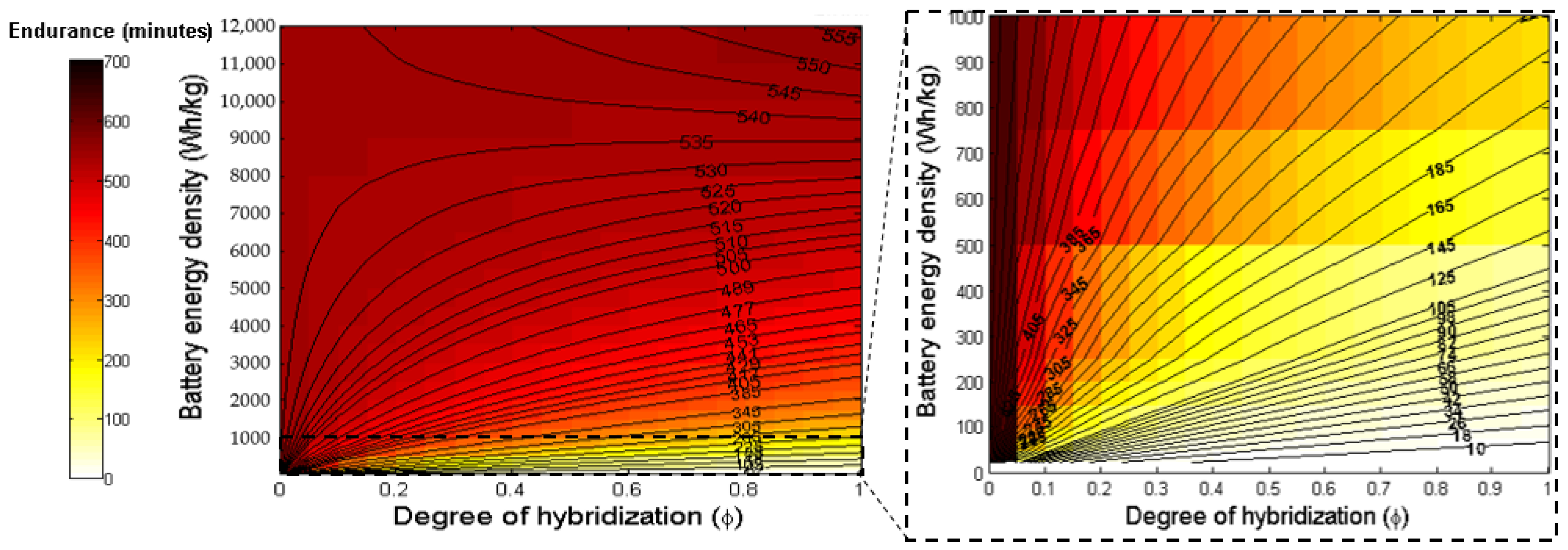
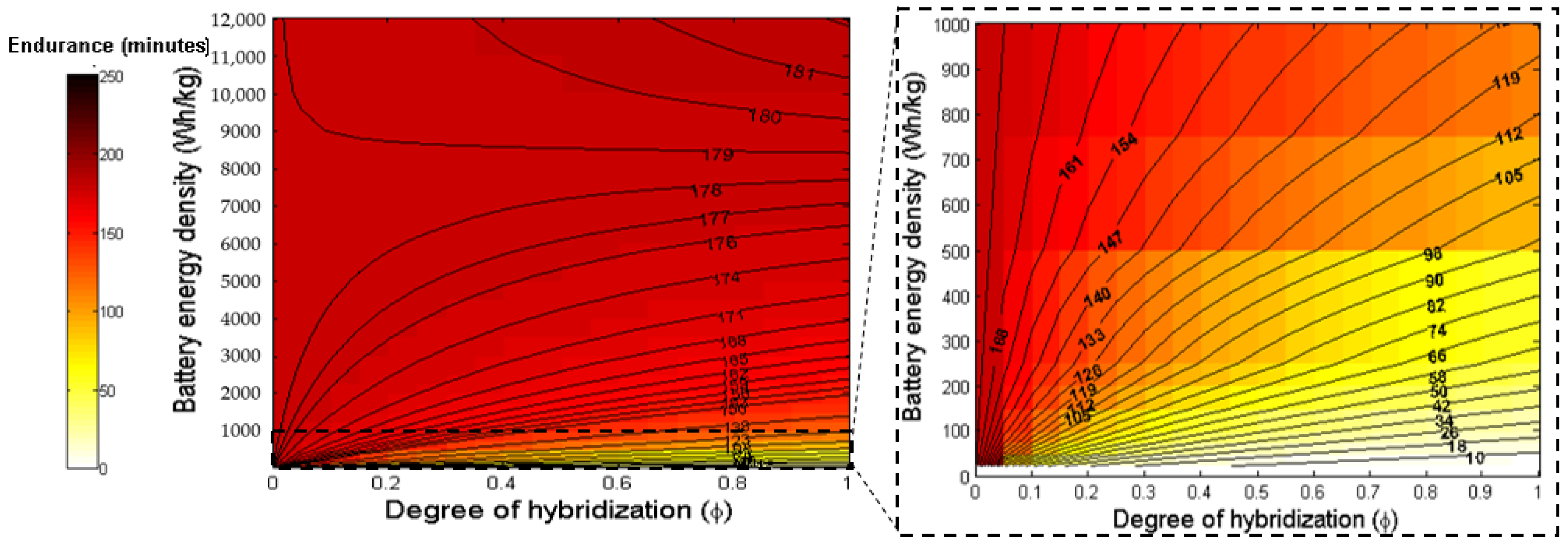
  • In the cases of parallel and series hybrid configurations, it is observed that there is an energy density threshold (EDT), below which the endurance reduces with an increase in degree of hybridization. Conversely, above EDT, endurance enhances with an increase in degree of hybridization. For any aircraft configuration, the EDT is not constant with degree of hybridization. For the parallel hybrid, the value ranges between 8960 < EDT < 9030 Wh/kg (in terms of the battery energy density), whereas in the series hybrid, it ranges between 8650 < EDT < 8950 Wh/kg (also in terms of the battery energy density). The higher value for the parallel hybrid is due to its higher dependence on a battery energy source. The exact values depend on the specific aircraft parameters given in Table 2. At the EDT, aircraft endurance is not dependent on degree of hybridization at all. This is probably because the effect of battery energy density and corresponding efficiencies becomes more prominent than the fuel energy density and corresponding efficiencies.
  • The significance of the value of the EDT becomes apparent when considering the current battery energy storage technologies. The current energy density of batteries lies at approximately 228 Wh/kg. This is expected to double approximately every 23 years [9] and, thus, this point lies way beyond the theoretical limits of battery energy densities. However, the endurance theory would still hold if another energy source would be able to fill the gap.
This paper works out a second case study (the ATR 72 equivalent aircraft). The ATR 72 is a regional aircraft. Regional aircraft serve 38% of the world city pairs and make up around 36% of the total flying hours [26,27]. Regional aircraft are projected to increase up to 3020 in number in the upcoming 20 years. Table 4 gives the input parameters for the second case study.
It can be observed that the results obtained for both of the case studies (Figure 4, Figure 5, Figure 6 and Figure 7) were very similar. Initially, the value of endurance decreases with the increase in degree of hybridization at low values of battery energy density and goes vice versa when the battery energy density is increased.
The EDT or the threshold at which the change happens when the variation reverses is observed at around 8500–9500 Wh/kg for the parallel hybrid case, while the values are around 8700–9200 Wh/kg for the series hybrid case.
It was also seen that as the MTOW and other weights of the ATR 72 equivalent are higher than the ones considered in the first case study, the endurance values for the former are on the lower side as compared to the latter. The other values for both case studies were considered similar because the first case study is an assumed one.

5. Conclusions

In this paper, a generalized endurance equation is derived for the hybrid-electric aircraft for a constant power split and degree of hybridization (φ) with an efficiency-based definition.
Limiting cases, namely φ = 0 (fully fueled) and φ = 1 (fully electric), were also investigated. It was observed that, at these limits, the endurance equation recedes to the Breguet equation and the electric aircraft endurance equation, respectively. The paper used the same case study as the range investigation in [1] to show the change in aircraft endurance with energy density of batteries and the degree of hybridization. For this specific aircraft design and hybrid-electric aircraft configuration with corresponding efficiencies, it was observed that an EDT value exists at which aircraft endurance is not dependent on degree of hybridization at all. Below the EDT, aircraft endurance reduces with the increase in degree of hybridization. On the contrary, above the EDT, aircraft endurance enhances with the increase in degree of hybridization.
It is a reality that the present limitations of battery energy storage technology with low energy density and high cost will limit the possibility of electric flight. Likewise, the idea of a hydrogen-fueled aircraft is also faced with several challenges in achieving the technology and infrastructure. The authors are of the belief that as a short-term, intermediate solution, hybrid electric aircraft technology might be used to fill this gap and can contribute in the shift towards net zero emissions. When applied to smaller aircraft with shorter range and endurance requirements, for example, regional aircraft, even a low degree of hybridization value can lead to an impressive reduction in fuel consumption and resulting emissions. Thus, the derivations of the range and endurance equations are important while designing a hybrid-electric aircraft and can also help validate their respective mission requirements.
Few differences were also observed between the aircraft range equation derived in the previous work by the authors [1] and the aircraft endurance equation derived in this paper. It was seen that aircraft range is affected by parameters such as lift to drag ratio, propulsive efficiency, battery and fuel energy density, payload weight and efficiencies, while aircraft endurance is affected by propulsive efficiency, battery and fuel energy density, payload weight and efficiencies. The reason behind the lack of dependency on the lift to drag ratio is that the endurance equation contains and is affected by the coefficients of lift and drag individually, while the range equation is affected by the lift to drag ratio as a whole. The dependency on coefficient of lift is more than the coefficient of drag in the aircraft endurance equation. It is also dependent on the wing planform area. Another difference between the equations is that aircraft range equation contains a logarithmic component which signifies that it has range changes logarithmically due to parameters, while the aircraft endurance changes linearly due to its parameters.

Author Contributions

Conceptualization, A.B., R.R. and R.C.; data curation, A.B.; formal analysis, A.B., R.R. and R.C.; funding acquisition, R.C.; investigation, A.B., R.R. and R.C., methodology, A.B. and R.R.; project administration, R.C.; supervision, R.C. and R.R.; resources, R.C.; visualization, A.B.; validation, R.C.; writing—original draft preparation, A.B.; writing—review and editing, A.B., R.C. and R.R. All authors have read and agreed to the published version of the manuscript.

Funding

The authors would also like to acknowledge the project: “Setting up of transdisciplinary research and knowledge exchange (TRAKE) complex at the University of Malta (ERDF.01.124)”, which is being co-financed through the European Union through the European Regional Development Fund 2014–2020 (www.eufunds.gov.mt).

Data Availability Statement

Data are contained within the article.

Conflicts of Interest

The authors declare no conflict of interest.

Nomenclature

AoAAngle of Attack
cLCoefficient of Lift
cDCoefficient of Drag
DDrag [N]
eSpecific Energy [J/kg]
EEnergy [J]
EDTEnergy Density Threshold
gGravitational acceleration [m/s2]
LLift [N]
PPower [W]
SPlanform area [m2]
tTime [s]
TThrust [N]
vVelocity [m/s]
WWeight [N]
γFlight path angle [rad]
ηEfficiency
φDegree of hybridization
ρDensity [kg/m3]
Subscripts
0Start of the mission
1,2,3Powertrain branch indices
batBattery
egElectrical generator
emElectrical motor
endEnd of mission segment
fFuel
gtGas turbine
gbGearbox
OEOperating Empty
pPropeller
PLPayload
startStart of mission segment
totTotal

References

  1. Batra, A.; Raute, R.; Camilleri, R. On the range equation for a hybrid-electric aircraft. Aerospace 2023, 10, 687. [Google Scholar] [CrossRef]
  2. Intergovernmental Panel on Climate Change (IPCC) 2022 Report. Available online: https://www.ipcc.ch/report/ar6/wg2/ (accessed on 24 April 2023).
  3. International Civil Aviation Organization (ICAO). Post-COVID-19 Forecasts Scenarios. Available online: https://www.icao.int/sustainability/Pages/Post-Covid-Forecasts-Scenarios.aspx (accessed on 24 December 2023).
  4. European Comission. Flightpath 2050 CARE2050. Europe’s Vision for Aviation. Available online: https://ec.europa.eu/transport/sites/transport/files/modes/air/doc/flightpath2050.pdf (accessed on 25 April 2023).
  5. European Comission. European Green Deal. Available online: https://ec.europa.eu/commission/presscorner/detail/en/ip_23_2389 (accessed on 22 December 2023).
  6. Schwab, A.; Thomas, A.; Bennett, J.; Robertson, E.; Cary, S. Electrification of Aircraft: Challenges, Barriers, and Potential Impacts; NREL/TP-6A20-80220; National Renewable Energy Laboratory (NREL): Golden, CO, USA, 2021. [Google Scholar]
  7. Hoelzen, J.; Silberhorn, D.; Zill, T.; Bensmann, B.; Rauschenbach, R.H. Hydrogen-Powered Aviation and Its Reliance on Green Hydrogen Infrastructure—Review and Research Gaps; Elsevier: Amsterdam, The Netherlands, 2022; Volume 47, pp. 3108–3130. [Google Scholar] [CrossRef]
  8. Zhang, L.; Butler, T.L.; Yang, B. Recent trends, opportunities and challenges of sustainable aviation fuel. In Green Energy to Sustainability: Strategies for Global Industries; John Wiley & Sons Ltd.: Hoboken, NJ, USA, 2020; pp. 85–110. [Google Scholar]
  9. Schäfer, A.W.; Barrett, S.R.H.; Doyme, K.; Dray, L.M.; Gnadt, A.R.; Self, R.; O’Sullivan, A.; Synodinos, A.P.; Torija, A. Technological, economic and environmental prospects of all-electric aircraft. Nat. Energy 2019, 4, 160–166. [Google Scholar] [CrossRef]
  10. Viswanathan, V.; Epstein, A.H.; Chiang, Y.; Takeuchi, E.; Bradley, M.; Langford, J.; Winter, M. The challenges and opportunities of battery-powered flight. Nat. Perspect. 2022, 601, 519–525. [Google Scholar] [CrossRef] [PubMed]
  11. Rossi, N.; Trainelli, L.; Riboldi, C.E.D.; Rolando, A. Conceptual Design of Hybrid-Electric Aircraft. Politechnico Di Milano, 2016–2017. Available online: https://hdl.handle.net/10589/139491 (accessed on 20 January 2024).
  12. Wheeler, P.; Sirimanna, A.S.; Bozhko, S.; Haran, K.S. Electric/Hybrid-Electric Aircraft Propulsion Systems. Proc. IEEE 2021, 109, 1115–1127. [Google Scholar] [CrossRef]
  13. Marciello, V.; Ruocco, M.; Nicolosi, F.; Stasio, M.D. Markey Analysis, TLARS selection and preliminary design investigations for a regional hybrid-electric aircraft. In Proceedings of the 33rd Congress of the International Council of the Aeronautical Sciences (ICAS), Stockholm, Sweden, 4–9 September 2022. [Google Scholar]
  14. Vries, R.D.; Hoogreef, M.F.M.; Vos, R. Range Equation for Hybrid-Electric Aircraft with Constant Power Split. J. Aircr. 2020, 57, 552–557. [Google Scholar] [CrossRef]
  15. Diehl, W.S. Three Methods of Calculating Range and Endurance of Airplanes; US Government Printing Office: Washington, DC, USA, 1925.
  16. Raymer, D. Aircraft desing: A conceptual approach. In AIAA Education Series, 4th ed.; American Institute of Aeronautics and Astronautics: Reston, VA, USA, 2006. [Google Scholar]
  17. Traub, L.W. Range and endurance estimates for battery-powered aircraft. J. Aircr. 2011, 48, 703–707. [Google Scholar] [CrossRef]
  18. Sadraey, M.H. Aircraft Performance: An Engineering Approach, 2nd ed.; CRC Press: Boca Raton, FL, USA, 2023. [Google Scholar] [CrossRef]
  19. Donateo, T.; Luigi, S. Fuel economy of hybrid electric flight. Appl. Energy 2017, 206, 723–738. [Google Scholar] [CrossRef]
  20. Nygren, C.K.P.; Major, R.R.S. Breguet’s Formulas for Aircraft Range and Endurance an Application of Integral Calculus. In Proceedings of the 1996 Annual Conference, Washington, DC, USA, 23 June 1996; pp. 1–90. [Google Scholar]
  21. Xie, Y.; Savvarisal, A.; Tsourdos, A.; Zhang, D.; Gu, L. Review of hybrid electric powered aircraft, its conceptual design and energy management methodologies. Chin. J. Aeronaut. 2021, 34, 432–450. [Google Scholar] [CrossRef]
  22. Finger, D.F.; Braun, C.; Bil, C. Comparative Assessment of Parallel-Hybrid-Electric Propulsion Systems for Four Different Aircraft. J. Aircr. 2020, 57, 843–853. [Google Scholar] [CrossRef]
  23. Zamboni, J.; Vos, R.; Emeneth, M.; Schneegans, A. A Method for the Conceptual Design of Hybrid Electric Aircraft. In Proceedings of the AIAA Scitech 2019 Forum, San Diego, CA, USA, 7–11 January 2019. [Google Scholar] [CrossRef]
  24. Bai, M.; Yang, W.; Li, J.; Kosuda, M.; Fozo, L.; Kelemen, M. Sizing methodology and Energy Management of an Air-Ground Aircraft with Turbo-Electric Hybrid Propulsion System. Aerospace 2022, 9, 764. [Google Scholar] [CrossRef]
  25. Taylor, A.E. L’Hospital’s Rule. Am. Math. Mon. 1952, 59, 20–24. [Google Scholar] [CrossRef]
  26. Project Report. Periodic Reporting for Period 3—GAM-2020-REG (REGIONAL AIRCRAFT 2020–2023). Available online: https://cordis.europa.eu/project/id/945548 (accessed on 20 January 2024).
  27. Clean Aviation. Available online: https://www.clean-aviation.eu/hybrid-electric-regional-aircraft (accessed on 2 April 2024).
  28. ATR Aircraft. Available online: https://www.atr-aircraft.com/aircraft-services/aircraft-family/atr-72-600/ (accessed on 2 January 2024).
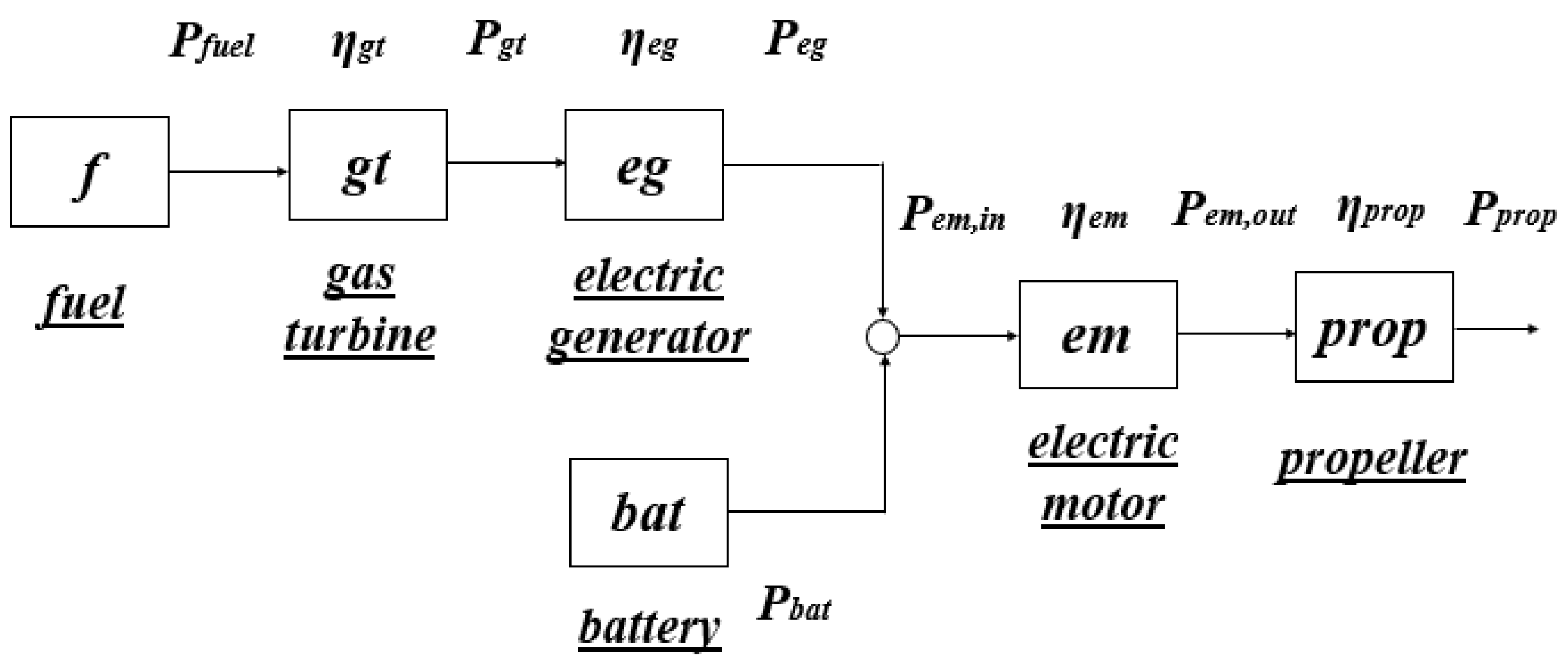
Figure 1. The series configuration of the hybrid-electric aircraft schematic [1].
Aerospace 11 00698 g001
Figure 2. The parallel configuration of the hybrid-electric aircraft schematic [1].
Aerospace 11 00698 g002
Figure 3. A generalized representation of the configurations [1].
Aerospace 11 00698 g003
Figure 4. Plot showing the aircraft endurance (minutes) in terms of energy density of batteries and the degree of hybridization for parallel hybrid. (The battery energy densities < 1000 are zoomed in).
Aerospace 11 00698 g004
Figure 5. Plot showing the aircraft endurance (minutes) in terms of energy density of batteries and the degree of hybridization for series hybrid. (The battery energy densities < 1000 are zoomed in).
Aerospace 11 00698 g005
Figure 6. Plot showing the ATR 72 equivalent aircraft endurance (minutes) in terms of energy density of batteries and the degree of hybridization for parallel hybrid. (The battery energy densities < 1000 are zoomed in).
Aerospace 11 00698 g006
Figure 7. Plot showing the ATR 72 equivalent aircraft endurance (minutes) in terms of energy density of batteries and the degree of hybridization for series hybrid. (The battery energy densities < 1000 are zoomed in).
Aerospace 11 00698 g007
Table 1. Definitions of the efficiencies related to both configurations.
Simplified Representation (Figure 3)Parallel Configuration
(or Mechanical-Node
Architecture) (Figure 2)
Series Configuration
(or Electrical-Node
Architecture) (Figure 1)
η 1 η g t η g t η e g
η 2 η e m 1
η 3 η g b η p η e m η g b η p
Table 2. The case study input parameters.
VariablesValues
Empty weight (WOE [N])50,000
Payload weight (WPL [N])20,000
Total input energy (Eo,tot [GJ])25
Gas turbine efficiency (ηgt)0.35
Electric motor efficiency (ηem)0.95
Electric generator efficiency (ηeg)0.98
Propulsive efficiency (ηp)0.80
Gearbox efficiency (ηgb)0.95
Energy density of aviation fuel (ef [Wh/kg])11,900
Acceleration due to gravity (g [m/s2])9.81
Coefficient of lift0.6391
Coefficient of drag0.0572
Planform area [m2]61
Density (at cruise altitude) [kg/m3]0.5579
Cruise velocity [m/s]141.67
Table 4. The ATR 72 equivalent [28] case study input parameters.
VariablesValues
Empty weight (WOE [N])127,040
Payload weight (WPL [N])68,670
Total input energy (Eo,tot [GJ])25
Gas turbine efficiency (ηgt)0.35
Electric motor efficiency (ηem)0.95
Electric generator efficiency (ηeg)0.98
Propulsive efficiency (ηp)0.80
Gearbox efficiency (ηgb)0.95
Energy density of aviation fuel (ef [Wh/kg])11,900
Acceleration due to gravity (g [m/s2])9.81
Coefficient of lift0.6391
Coefficient of drag0.0572
Planform area [m2]61
Density (at cruise altitude) [kg/m3]0.5579
Cruise velocity [m/s]141.67
Disclaimer/Publisher’s Note: The statements, opinions and data contained in all publications are solely those of the individual author(s) and contributor(s) and not of MDPI and/or the editor(s). MDPI and/or the editor(s) disclaim responsibility for any injury to people or property resulting from any ideas, methods, instructions or products referred to in the content.

