Article

The Development of a Next-Generation Latticed Resistojet Thruster for CubeSats

Space Science and Technology Centre, School of Earth and Planetary Sciences, Curtin University, Perth, WA 6845, Australia
*
Author to whom correspondence should be addressed.
Aerospace 2024, 11(9), 714; https://doi.org/10.3390/aerospace11090714
Submission received: 29 July 2024 / Revised: 29 August 2024 / Accepted: 30 August 2024 / Published: 31 August 2024

Abstract

:
CubeSat and small satellite resistojet heat exchanger designs are based on conventional concepts that have been used since the 1960s, being primarily limited to helical or twisted tape heat exchangers. The design flexibility enabled by new additive manufacturing technologies is yet to be properly harnessed. This study introduces a novel resistojet concept that incorporates a highly miniaturized lattice structure as the heat exchanger. A conjugate heat transfer analysis determined that the lattice with a diamond unit cell had superior thermal performance compared to the same lattice with a gyroid unit cell and increased the heat transfer rate by up to 11% compared to a helical heat exchanger of the same volume. Performance testing of the prototype thruster with integral diamond lattice indicated that specific impulses of up to 94 s were possible with a 30-Watt heater using nitrous oxide as the propellant. The prototype thruster weighed only 22 g and demonstrated a 67% reduction in the power required to achieve the same specific impulse as previous nitrous oxide resistojets designed for the small satellite platform. The development of highly miniaturized latticed resistojets is shown to be feasible and highly attractive for CubeSats, where mass and power are of the utmost importance.

1. Introduction

CubeSat mission capabilities are becoming more advanced, with numerous interplanetary and lunar missions recently being launched [1]. To support these complex missions, miniaturized propulsion technologies are critical for providing orbital maneuvers, station keeping, attitude control, and reaction wheel desaturation. Subsequently, considerable efforts have been focused on rapidly developing CubeSat propulsion systems over the last decade [2]. Nitrous oxide bipropellant systems in particular have shown great uptake in the commercial space market, with companies such as Dawn Aerospace having more than 50 operational nitrous oxide bipropellant thrusters in orbit as of 2023 [3]. Due to its very low freezing temperature (−90 °C), nitrous oxide propulsion is well suited for long-term storage in cold deep space environments. As future mission scenarios outside Earth orbit, such as the moon and Mars, lack planetary magnetic fields, magnetorquers are not capable of attitude control, and thruster-based attitude control is growing in popularity [4]. Thruster-based attitude control for CubeSats has primarily been achieved through the use of cold gas thrusters—which is the most mature type of CubeSat propulsion [5], although their specific impulse is inherently low due to low operating temperatures.
To support future CubeSat missions with more demanding Delta-V requirements, resistojet thrusters are an attractive alternative for providing attitude control, offering considerable performance enhancements over traditional cold gas thrusters due to increased propellant temperatures [2]. For nitrous oxide-based systems, multi-mode systems are feasible, whereby a nitrous oxide-based bipropellant thruster is used for primary propulsion, and nitrous oxide resistojet thrusters are used for attitude control. Such systems can share propellant tanks and hardware to save mass since they operate from the same propellant.
System mass optimization for small satellite propulsion systems has been shown to be at least as effective as improvement in a thruster’s specific impulse [6]. A comprehensive review on multi-mode spacecraft propulsion conducted by Rovey et al. concluded that the reduced inert mass of multi-mode propulsion systems due to shared resources benefits small satellites the most [7]. Furthermore, an example analysis illustrated that the system integration mass savings possible with multi-mode propulsion are mission enabling for lunar CubeSat missions [7]. Hence, although nitrous oxide has a mediocre specific impulse due to its relatively heavy molecular mass, the system mass reductions possible when using nitrous oxide resistojets for attitude control in a multi-mode propulsion system can result in improved Delta-V capability for CubeSats. Furthermore, the reduction in system components enhances the system reliability, which is critical for deep space CubeSat missions, especially when considering the high propulsion system failure rate of recent lunar CubeSat missions [8,9]. This trade-off has led to the development of a novel nitrous oxide-based multi-mode propulsion system in a collaboration between Curtin University and InSpacePropulsion Technologies (a spinoff company from the German Aerospace Centre). The system is intended for a future lunar CubeSat mission, which uses the nitrous-based bipropellant thruster developed by InSpacePropulsion Technologies and the German Aerospace Centre [10] for orbital maneuvering and station keeping, with nitrous oxide resistojets for attitude control and back-up propulsion. This work details the development of the resistojets that will be utilized for this novel propulsion architecture.
Resistojets need to be low cost, have minimal volume and mass, and have high thermal efficiency to reduce spacecraft power requirements and comply with CubeSat constraints. However, simultaneously miniaturizing the thruster and maintaining high thermal efficiency is difficult, as reducing the thruster size subsequently reduces the heat-exchanging time and flow path. Therefore, miniaturized resistojets suitable for the CubeSat platform require highly compact and efficient heat exchangers. State-of-the-art CubeSat resistojets have employed miniaturized versions of traditional heat-exchanging concepts, such as helical heat exchangers [4] and twisted tape heat exchangers [11], which have been utilized since the inception of the resistojet in the 1960s [12]. The helical heat exchanger is a well-established technology for resistojet thrusters, having been used for Surrey Satellites Technology Limited’s (SSTL’s) family of resistojet thrusters for small satellites for more than 20 years [13]. Twisted tape heat exchangers are simple and can be easily miniaturized, but they have demonstrated low thermal efficiencies and result in relatively high pressure drop [14]. State-of-the-art resistojets have been developed for larger satellite platforms using additively manufactured concentric cylinder heat exchangers [15,16]. In these concepts, the thruster itself acts as a resistive heater and regenerative heat recuperator, which can result in high thermal efficiencies [15]. However, as the heat generation with these concepts is proportional to the thermal resistance of the heat exchanger—which reduces significantly with smaller electrical path lengths—the concept does not perform as effectively at the significantly reduced scale of CubeSat thrusters.
In this study, a novel resistojet thruster concept is introduced that uses an entirely new heat exchanger concept. The thruster is additively manufactured as a highly miniaturized single piece with a geometrically complex Triply Period Minimal Surface (TPMS) lattice structure as the heat exchanger. A conjugate heat transfer analysis was conducted to compare the thermal performance of the TPMS latticed heat exchanger with a helical heat exchanger within the same volume. Propulsive testing with a prototype thruster was undertaken in vacuum conditions to measure the performance compared to a cold gas operation with nitrous oxide as the propellant. Although initially intended to be used as an attitude control thruster for a nitrous-based multi-mode system, the thruster concept can also be utilized for primary propulsion for smaller CubeSats with a wide variety of propellants.

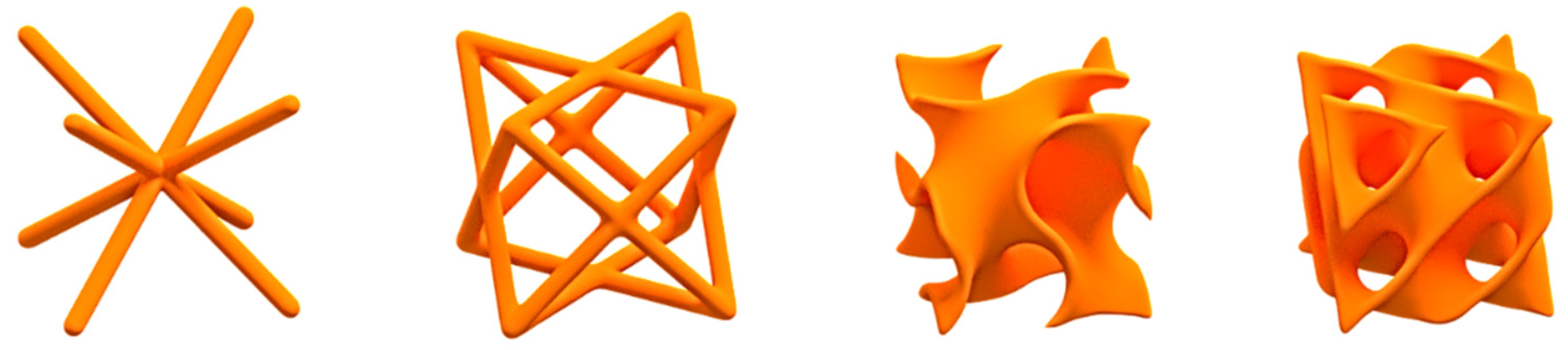
2. Literature Review of Lattice Structures and Their Heat Transfer Applications

The three-dimensional lattice structure was first proposed by Evans et al. [17] in 2001 as a prospective opportunity for ultra-light structures, compact cooling, energy absorption, and vibration control. Lattice structures belong to the overarching family of cellular structures and are generally defined as porous three-dimensional structures formed and tessellated by repeating unit cells with varying topological geometries [18]. Common unit cell topologies that have been investigated in the literature are illustrated in Figure 1 and include the body-centered cubic (BCC) and face-centered cubic (FCC) cells [19], which belong to the family of strut-based lattice structures, and the Schoen gyroid and Schwartz diamond [20], which belong to the family of TPMS lattice structures. The vast majority of additively manufactured lattice research has been dedicated to investigating structures with patient-specific surfaces and stiffness for medical implants in the biomedical industry and for making ultra-lightweight and strong parts for the aerospace industry [21]. Recently, however, TPMS lattice structures are receiving significant interest for heat transfer applications [15,17,18,19,20].
In the literature, TPMS unit cell geometries are almost exclusively investigated for heat transfer applications—particularly gyroid topologies—as TPMS offer numerous advantages over strut-based topologies. Unlike strut-based lattices, they naturally split the flow domain into two paths, which is necessary for typical fluid-to-fluid heat exchanger applications. For solid–gas heat exchangers, as is the case for a resistojet thruster, splitting the flow domain is not necessary. TPMS topologies also offer potential manufacturing advantages over strut-based topologies, as the angle of the cell walls constantly vary, meaning subsequent layers have better support during the AM fabrication process [21], and the smooth profiles of TPMS structures eliminate the stress concentrations generated at the junction of strut-based topologies [22]. A conclusive comparison of the convective heat transfer performance of TPMS and strut-based lattice structures has not been demonstrated but is outside the scope of this study. Due to the manufacturing advantages, only TPMS lattice topologies were considered and analyzed for the remainder of this work.
Advancements in additive manufacturing processes now permit the fabrication of miniaturized TPMS lattice structures with unit cell sizes on the order of approximately 5 mm [23]. The fabrication of TPMS lattice structures is aided due to their self-supporting geometry, which circumvents the requirement for internal support structures during the printing process. These lattice structures are inherently excellent at maximizing convective heat transfer, as they offer an increased surface area-to-volume ratio when compared to traditional heat exchangers [24]. Their inherently high surface area-to-volume ratio has been demonstrated to significantly reduce the size of heat exchangers by up to 60% when compared to traditional heat exchanger technologies [20]. Furthermore, their complex geometry induces strong turbulent mixing for heat transfer enhancement and boundary layer destruction [25], while the continuous surface lowers the pressure drop and prevents the formation of dead zones in the flow [26]. Such characteristics suggest that TPMS structures are promising candidates for CubeSat resistojet applications, where high thermal efficiency and low volume and mass are required simultaneously.
Examples of significant thermal efficiency improvements and miniaturization with TPMS heat exchangers have been reported in the literature for terrestrial fluid-to-fluid heat exchanger applications. Dixit et al. [27] manufactured and tested a gyroid latticed liquid–liquid heat exchanger via stereolithography as a single ready-to-use unit. X-ray computed tomography imaging confirmed that the heat exchanger was manufactured defect free, with measurements indicating an overall heat transfer coefficient of 120–160 W/m2K for the hot fluid with a Reynolds number of 10–40. Most impressively, the experimental results showed a 55% increase in heat exchanger efficiency for the additively manufactured gyroid latticed heat exchanger in comparison to a traditional thermodynamically equivalent counter-flow heat exchanger at just 10% of its size. Mahmoud et al. [24] manufactured and tested four gyroid heat exchangers with varying geometrical characteristics and one conventional heat exchanger for comparison via laser powder bed fusion. All the gyroid heat exchangers provided greater than 50% improvements in the heat exchanger effectiveness compared to the conventional shell and tube heat exchanger. After the inspection and testing of the lattice structures with various thicknesses, it was recommended to print AlSi10Mg gyroid heat exchangers with a thickness of more than 0.5 mm when using laser powder bed fusion to avoid manufacturing defects.
The majority of studies that investigate TPMS geometries for heat transfer focus on fluid–fluid applications with gyroid structures. Very few studies in the literature explore the potential benefits of TPMS lattices in forced convection configurations [22], which is the configuration most similar to a resistojet heat exchanger. One such study that investigated the performance of different TPMS unit cell topologies in a forced convection configuration was conducted by Tang et al. [26]. This study compared the heat transfer performance of the gyroid, the diamond, and the I-graph-Wrapped Package (IWP) TPMS topologies numerically and experimentally. The diamond topology was measured to have the highest convective heat transfer coefficient, followed by the gyroid and then IWP topologies. It was deduced that the absence of through holes in the diamond lattice structure forces the fluid into the non-flow channel formed by the complex curved surface of the diamond cell, thereby enhancing the destruction of the boundary layer and generating more secondary flow patterns and vortices [26].
In summary, the literature survey clearly identified that enhanced thermal performance and significant size reductions are possible with TPMS latticed heat exchangers when compared to traditional heat exchangers. Maximizing thermal performance and minimizing size are the two driving performance variables for CubeSat resistojets propulsion, and thus, TPMS lattices show promising characteristics for this application. The popularity of the gyroid structure for heat exchangers may be unwarranted, as conclusive evidence to its superiority is yet to be demonstrated, as studies comparing different TPMS unit cell topologies are very scarce. For forced convection scenarios in particular, the reference study by Tang et al. suggests that the diamond unit cell is in fact superior. For this reason, this study will conduct a conjugate heat transfer analysis to compare the performance of the gyroid and diamond TPMS unit cells for a resistojet heat exchanger application, providing much needed data for the performance and benefits of TPMS in forced convection applications for the wider heat transfer community. There are no studies in the literature that explore the potential benefits of using TPMS lattice structures for resistojet propulsion, and thus, this study will lay the groundwork for a new resistojet concept that offers compelling advantages for future spacecraft of all sizes, with particular advantages for small spacecraft and CubeSats (see Section 8).

3. Resistojet Thruster Design

3.1. Thruster Concept and Parameters

The resistojet thruster proposed in this work has the purpose of providing momentum control and back-up primary propulsion for the Binar Prospector mission—a 12U CubeSat intended to perform low-altitude magnetometry of the lunar surface. The resistojet thruster utilizes nitrous oxide as the propellant, which is delivered to the resistojet from the oxidizer tank of the multi-mode propulsion module. Using resistojets rather than cold gas thrusters for attitude control is necessary for the mission since propellant quantity is the primary factor influencing the mission lifetime. From the mission thrust requirement of 200 mN for the resistojets, the targeted thruster operating parameters could be calculated from gas dynamic relations and isentropic flow assumptions (see Table 1).
The thruster is designed to be monolithic, combining the heat exchanger, thruster body, and supersonic nozzle into a single piece as illustrated in Figure 2. The cartridge heater is located in the center of the resistojet along the thrust axis, while the propellant is fed into the thruster tangentially from a miniaturized solenoid valve.

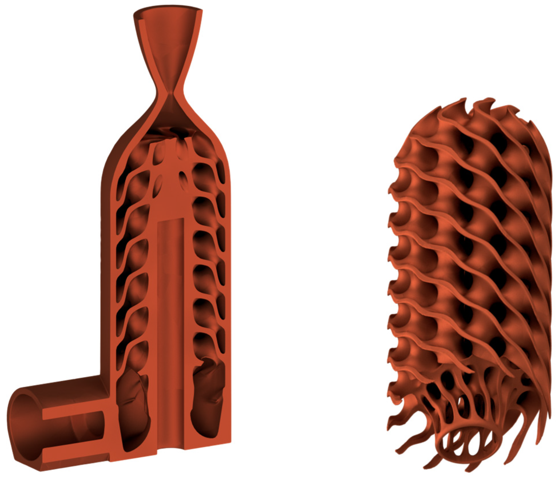
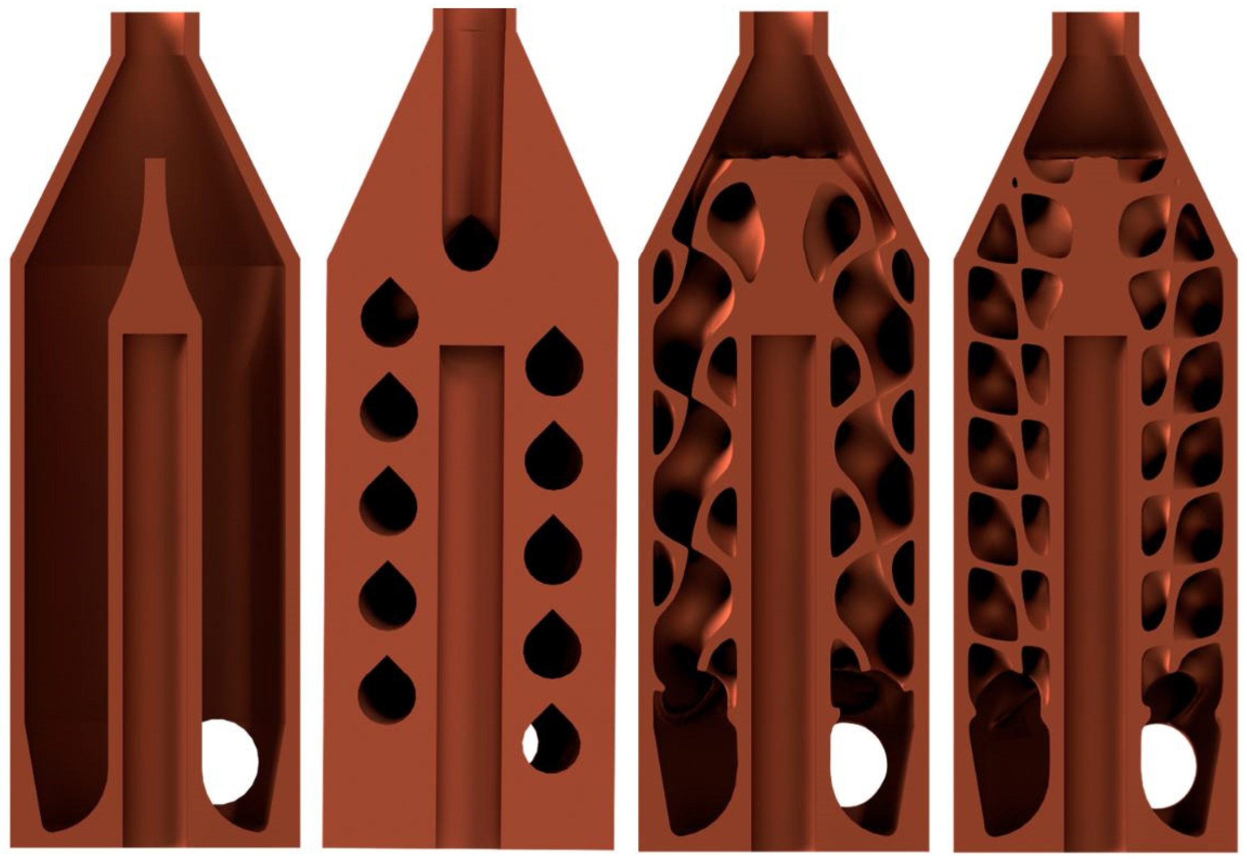
3.2. Heat Exchanger Design

The most important design drivers for the resistojet are to maintain reliable operation and maximize thermal efficiency, both of which are primarily influenced by the heater and heat exchanger design. The heater can transfer energy to the propellant either by direct heating, where the propellant is in direct contact with the heater, or via indirect heating, where the heater is located within the thruster body and transfers energy to the heat exchanger body, which then ultimately heats the propellant. Direct heating can offer higher performance since the propellant can achieve a temperature closer to that of the heater [28]. However, as reliability is considered paramount, the indirect heating method was selected, as exposure to high-temperature nitrous oxide will result in oxidation and corrosion, which can reduce the heater lifetime. The thermal energy is provided by a miniaturized 1/8 inch diameter cartridge heater, which transfers heat primarily by conduction to the heat exchanger body, which then ultimately heats the propellant. The cartridge heater is located centrally along the axis of thrust so that thermal energy conducted away in the radial direction is primarily transferred to the propellant, reducing the exterior surface temperature and thermal radiation losses.
Maximizing the convective heat transfer to the propellant to increase the propellant temperature and thruster performance is the primary function of the resistojet heat exchanger. To accomplish this, the heat exchanger should maximize the convective heat transfer coefficient and heat-exchanging surface area within the specified volume. For small satellite resistojets that typically have very small volume allotments and operate at low Reynolds numbers, swirling the propellant to promote mixing is often employed to increase the convective heat transfer. Swirling the propellant in small satellite resistojet heat exchangers has been shown to increase the heat flux by a factor of 2.5 compared to straight propellant flow [14]. This technique is commonly employed by forcing the propellant to flow in a helical path around helically wound heater wire [13,29]. Other techniques involve inserting a helical wire or twisted tape in the chamber to act as the heat exchanger [11] or injecting the propellant tangentially to establish a swirling flow that rotates about the thrust axis [14]. With the advent of additive manufacturing, resistojet heat exchangers now have unprecedented design flexibility and can contain intricate interior geometries for mixing and swirling the propellant to enhance the heat exchanger performance. This work aims to assess the feasibility and performance of using an additively manufactured lattice stucture as the heat exchanger for a resistojet.
The lattice structure was created in the software nTop using its implicit modeling capabilities. To improve the convective heat transfer between the latticed heat exchanger and the propellant, it is desirable to have a lattice structure with high porosity. This can be achieved by reducing the unit cell size and thickness of the lattice to increase the effective surface area for heat exchange. The thickness and unit cell size are highly dependent on manufacturing limitations. Based on the manufacturing results of gyroid lattice structures in [24], the minimum lattice thickness and unit cell dimensions were specified to be 0.6 mm and 6 × 6 × 7 mm, respectively. The unit cell was slightly stretched in the vertical direction to reduce the aspect ratio to eliminate overhang and improve the design for additive manufacturing. The thickness of the lattice structure is controlled by a scalar field that increases the wall thickness from 0.6 mm at the interface with the outer thruster body to 0.8 mm at the interface with the cartridge heater. This increases the conductive surface area near the heat source to transfer thermal energy more effectively from the heater throughout the lattice structure. A Boolean subtraction of a toroidal body was performed on the bottom of the lattice structure to reduce overhang and ensure manufacturability. A section view of the latticed resistojet thruster concept with a diamond TPMS heat exchanger with the aforementioned lattice parameters is illustrated in Figure 3.

3.3. Material Selection

The most important material characteristics for the thruster were the thermal conductivity and maximum operating temperature. The resistojet is designed to be capable of providing primary propulsion, which necessitates longer warm-up periods and higher operational temperatures to improve the propulsive efficiency. Therefore, maximum service temperatures above 500 degrees Celsius are desirable. High thermal conductivity will reduce the thruster warm-up period and subsequently reduce energy consumption, which is highly desirable for small spacecraft with strict power budgets. Furthermore, utilizing more thermally conducting materials has been shown to achieve higher normalized performance for TPMS heat sinks, as reduced conductivity results in large thermal gradients between the heat source and lattice, which reduces the effective heat transfer surface available [30]. For these reasons, GRCop-42 was selected for the thruster material due to its high thermal conductivity and operating temperature. The relevant material properties of GRCop-42 are listed in Table 2 below.
GRCop-42 is a highly conductive, high-strength copper alloy comprised copper, chromium, and niobium. The alloy was developed by NASA’s Glenn Research Center specifically for use in high-heat flux applications such as rocket engine combustion chambers [31]. GRCop-42 can be manufactured using laser powder bed fusion techniques, such as selective laser melting or laser powder direct energy deposition and offers significant advantages for resistojet thrusters. Most notably, the material has a high thermal conductivity and can retain its material strength at sustained wall temperatures of up to 730 °C [31]. Additionally, the alloy offers strong resilience to oxidation during aggressive test environments [31], which is important for nitrous oxide resistojets since the propellant is an oxidizer.

4. Conjugate Heat Transfer Analysis

4.1. Purpose and Scope

A conjugate heat transfer (CHT) analysis was undertaken using ANSYS Fluent 2024 R1 to compare the performance of four resistojet heat exchanger designs. The objective of the study is to identify which heat exchanger geometry maximizes the heat transfer rate (Q) and the areal convective heat transfer coefficient—the product of the convective heat transfer coefficient (h) and the available heat-exchanging surface area (A) within the constrained volume. The available heat exchanger volume envelope is constrained to be a cylinder with a diameter of 14 mm and a length of 32 mm, which includes the volume required for the central 1/8 inch diameter and 1-inch-long cartridge heater. The first two concepts utilize traditional resistojet heat exchanger designs that swirl the propellant around a central heater. Concept 1 injects the propellant tangentially into a cylindrical and empty chamber to achieve swirling. Concept 2 incorporates an additively manufactured channel that forces the propellant to flow in a helical manner around the heater. Concepts 3 and 4 incorporate an additively manufactured TPMS gyroid and diamond lattice structure as the heat exchanger, respectively, forcing the propellant to flow through many tortuous paths to promote mixing. The four heat exchanger concepts are illustrated in Figure 4 below.
The CHT analysis is undertaken at steady-state conditions and only considers the resistojet heat exchanger to analyze the convective heat transfer performance, as such a flow is incompressible. The physics between the heat transfer in the solid and turbulent fluid flow is coupled. For the solid geometry, the heat transfer is described by Fourier’s equation:
ρ C p T t = · k T
where ρ , C p , and k are the density, specific heat capacity, and thermal conductivity of Gr-Cop42, as listed in Table 2, and T is the variation in temperature in terms of time and position. The fluid flow is governed by the incompressible form of the Navier–Stokes equations, including continuity and the conservation of momentum and energy, as seen in Equations (2)–(4) below.
· u = 0
ρ u t + u · u = p + μ 2 u + ρ g  
ρ C p T t + u · T = · k T

4.2. Meshing and Boundary Conditions

The entire heat exchanger geometry was included in the analysis. A coupled polyhedral conformal volume mesh was used for meshing the solid and fluid domains. Seven inflation layers were imposed in the fluid domain at the interface boundary with the solid to capture the boundary layer. The mesh for each concept was refined until the area weighted average of the y+ distance was below unity. An illustration of the fluid mesh used for each concept is displayed in Figure 5, and the number of cells for each heat exchanger concept is listed in the caption. Evidently, Concept 3 and 4 with the gyroid and diamond latticed heat exchangers required significantly more cells in order to adequately resolve the complex internal geometry and fluid path.
The boundary conditions for each analysis were kept constant. Each heat exchanger was simulated at four different mass flow rates ranging from the design mass flow rate of 0.2 g/s to 0.35 g/s. This mass flow rate range was specified to highlight the trends in thermal performance with an increased mass flow rate for higher thrust versions of the thruster in the future. The interface between the cartridge heater and thruster wall was specified as a constant temperature boundary condition equal to 373.15 K. This temperature was chosen because the thruster could maintain this wall temperature at steady state with its limited power consumption (up to 30 Watts) for the range of mass flow rates investigated. Nitrogen was utilized as the fluid. The calculation of the Reynolds number at the inlet for each concept at the range of mass flow rates showed that the Reynolds number varied from 4200 to 7400. Thus, the flow was considered to be in the turbulent regime and the k-e turbulence model was used to resolve the Navier–Stokes equations. The full list of boundary conditions are specified in Table 3.

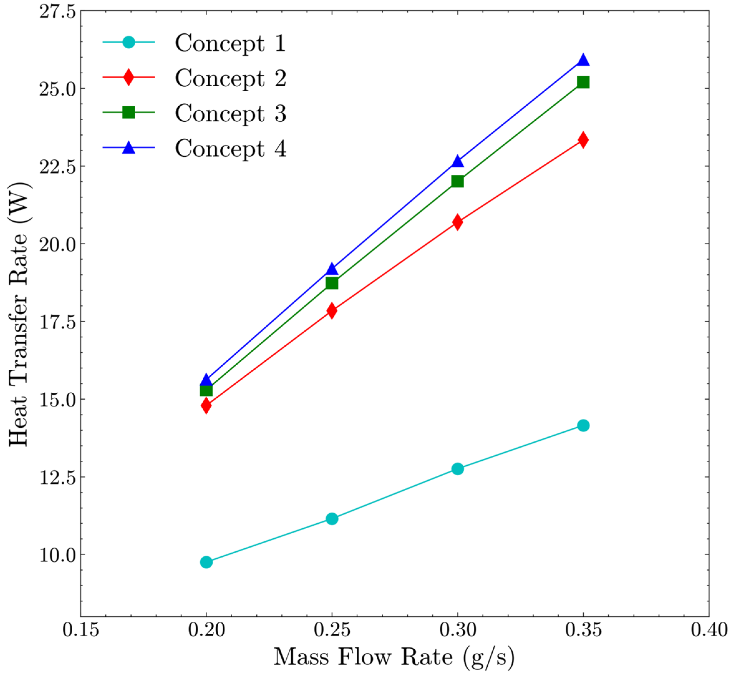
4.3. Design Screening Analysis

The numerical analysis had the purpose of identifying which heat exchanger concept had the highest thermal performance. This was determined by extracting the areal heat transfer coefficient and maximum heat transfer rate at each mass flow rate. The comparison of the convective heat transfer performance for the four concepts within the flow range investigated in this work can be seen in Figure 6 and Figure 7 below.
Compared to Concept 1—the baseline reference—the helical heat exchanger (Concept 2) and the TPMS gyroid and diamond heat exchangers (Concepts 3 and 4) show significant improvements in the areal convective heat transfer coefficient and the overall convective heat transfer rate. Concept 2 has a 31% reduction in heat-exchanging surface area compared to Concept 1, albeit the heat transfer rate is 51–65% higher over the mass flow rates investigated due to the considerable enhancement of 89–100% in the convective heat transfer coefficient. This highlights the significant influence that geometry can have in enhancing the convective heat transfer performance of miniaturized resistojet heat exchangers. The significant increase in the convective heat transfer coefficient for Concept 2 is attributed to the influence of swirling the fluid, which enhances the bulk mixing in combination with increased fluid velocity throughout the heat exchanger due to the reduction in the hydraulic diameter from 5.2 to 3 mm.
The TPMS diamond and gyroid heat exchangers show further increases in thermal performance than Concept 2, with the diamond heat exchanger (Concept 4) showing the greatest overall performance. The heat transfer rate of the diamond and gyroid heat exchangers are 60–83% and 57–78% higher than Concept 1 and 6–11% and 3–8% higher than Concept 2, respectively. Furthermore, as the mass flow rate increases, the disparity between the convective heat transfer performance of the diamond and gyroid TPMS heat exchangers compared to Concept 1 and 2 tends to become larger. The areal convective heat transfer coefficient of Concept 4 is 8–10% higher than Concept 3; however, the surface averaged convective heat transfer coefficient for Concept 4 was on average 7% lower than Concept 4. Therefore, the enhancement in the convective heat transfer performance for the diamond heat exchanger is primarily attributed to the 18% increase in surface area compared to the gyroid heat exchanger. The design screening analysis has highlighted that TPMS lattice structures can provide considerable performance enhancements for resistojet thrusters due to the combination of their high surface area-to-volume ratio and convective heat transfer coefficient. Up to 11% increases in the heat transfer rate were shown to be possible compared to traditional concepts, such as helical heat exchangers. Concept 4 with the diamond TPMS heat exchanger demonstrated superior thermal performance, and thus, this design was selected to proceed to the prototype manufacturing and testing phase of this study. A cross-section of the temperature distribution for the diamond latticed heat exchanger is illustrated in Figure 8 to show the heat transfer path from the heater to the propellant.

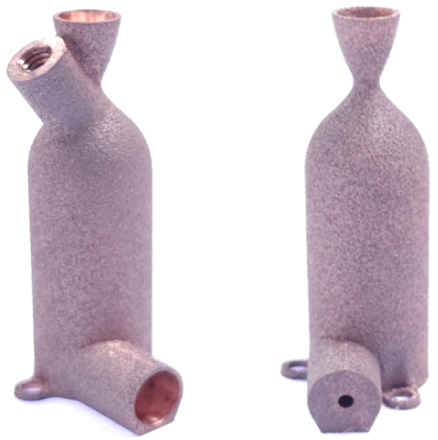
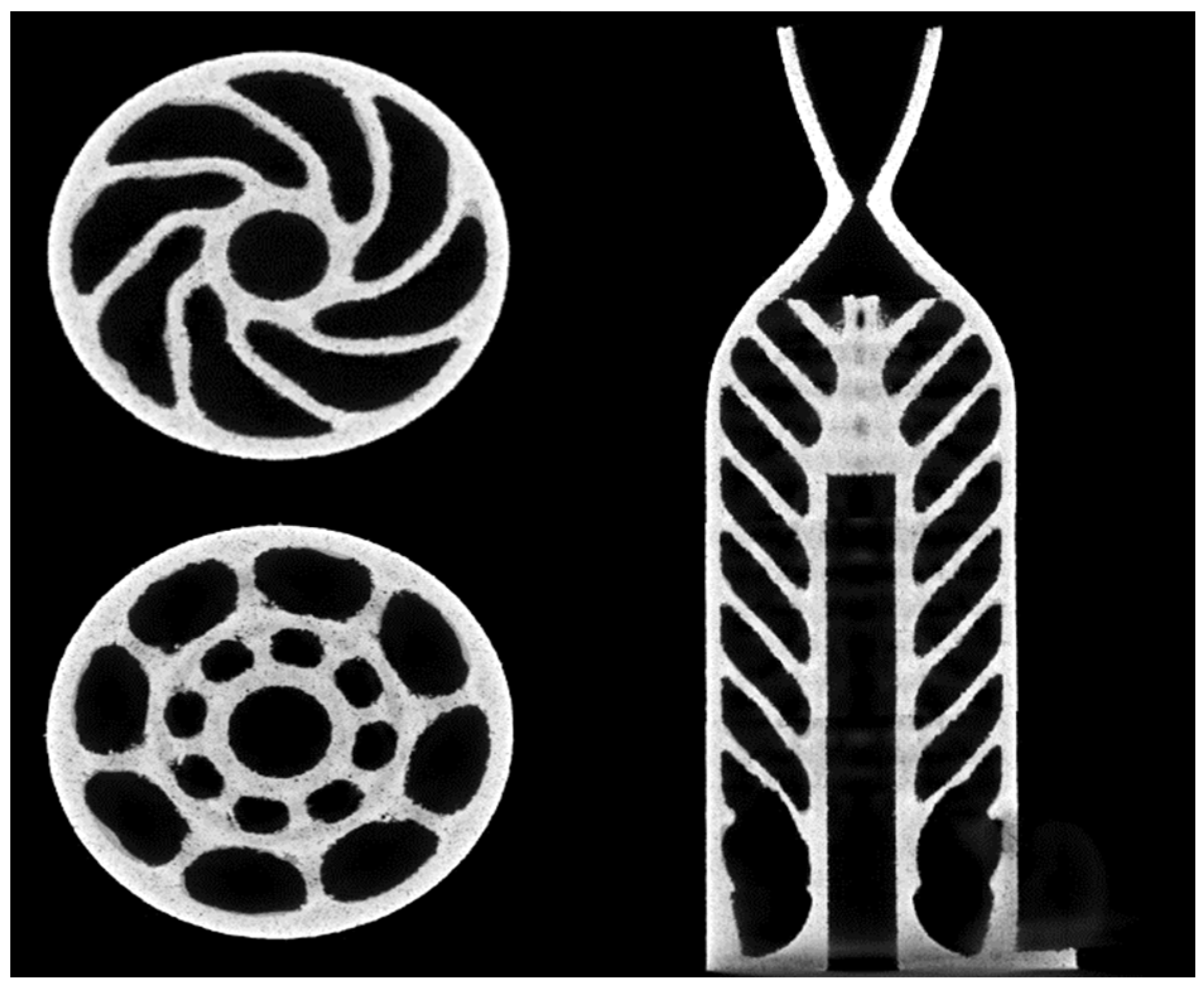
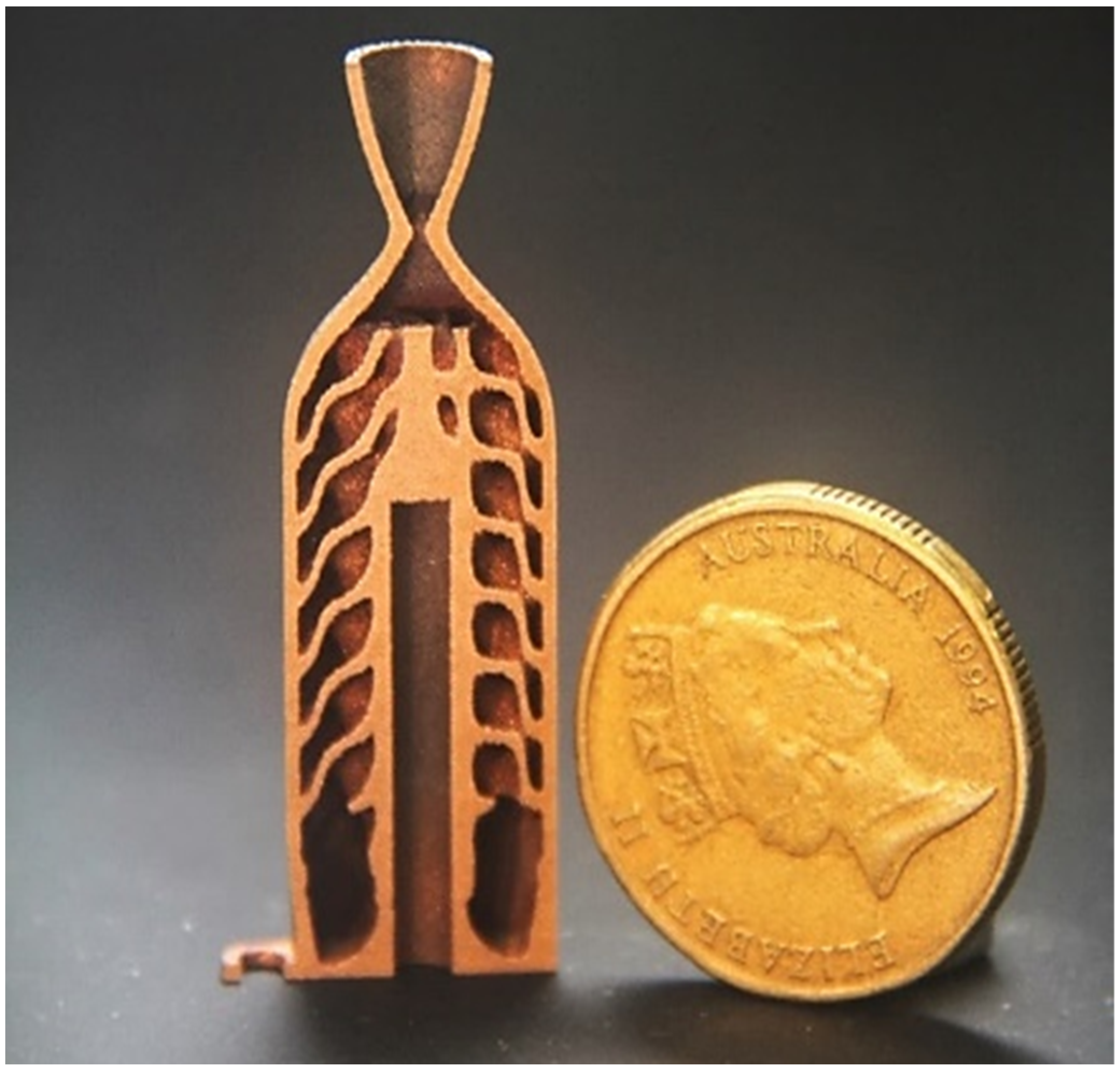
5. Prototype Thruster

Two prototype thrusters were additively manufactured from GRCop-42 using selective laser melting (SLM), as seen in Figure 9. Both thrusters had the same diamond TPMS latticed heat exchanger internally, which was identical to the heat exchanger corresponding with Concept 4. The thruster that was used for experimental tests underwent post processing and contained a measurement port for chamber pressure and temperature measurements. The other thruster was printed with no post-processing and was utilized for manufacturing analysis.
Due to relatively high costs and additive manufacturing difficulties, manufacturing and experimental thermal performance investigations of copper lattices are still relatively scarce [23]. The manufacturability and thermal performance analysis of GRCop-42 lattice structures is unexplored in the literature. Thus, the investigations conducted in this study will contribute important knowledge to understanding the manufacturability and performance of GRCop-42 TPMS lattice structures, which show promise for high-temperature heat transfer applications.
To assess the manufacturability of the internal latticed heat exchanger, micro-X-ray Computed Tomography (XCT) and a destructive visual analysis were performed. The XCT analysis was undertaken at the Australian Resources Research Centre, part of the Commonwealth Scientific and Industrial Research Organization. A Zeiss Versa XRM 520 X-ray microscope was used to scan the sample in three dimensions. The instrument was set up to 160 kV, 10 W with 2401 projections recorded over 360 degrees. Each projection was used to generate the 3D volume with beam hardening corrected during reconstruction and ring artefacts removed during acquisition. Data were processed with Avizo3D software (TM) to allow for the easy inspection of the interior in three spatial directions. Cross-sectional scans of the thruster can be seen in Figure 10.
The XCT analysis illustrated that there were no manufacturing defects or voids present throughout the thruster body and lattice structure. The analysis demonstrated that additively manufacturing a GRCop-42 TPMS diamond structure via SLM with a 6 mm unit cell size and minimum wall thickness of 0.6 mm is feasible. Small amounts of trapped powder were identified from the XCT results in some locations where the lattice bonded with the outer thruster surface. This suggested that ultrasonic cleaning alone was not sufficient for powder removal, and an additional pressurization with inert gas was then performed which was confirmed to remove the powder after destructive inspection. A visual inspection of the sliced internal structure was conducted after cutting the thruster along the thrust axis with a wire electron discharge machine, with the resulting cut illustrated in Figure 11. The inspection identified no additional defects, demonstrating that the miniaturized resistojet with the internal diamond TPMS lattice structure is manufacturable with GRCop-42.

6. Experimental Methodology

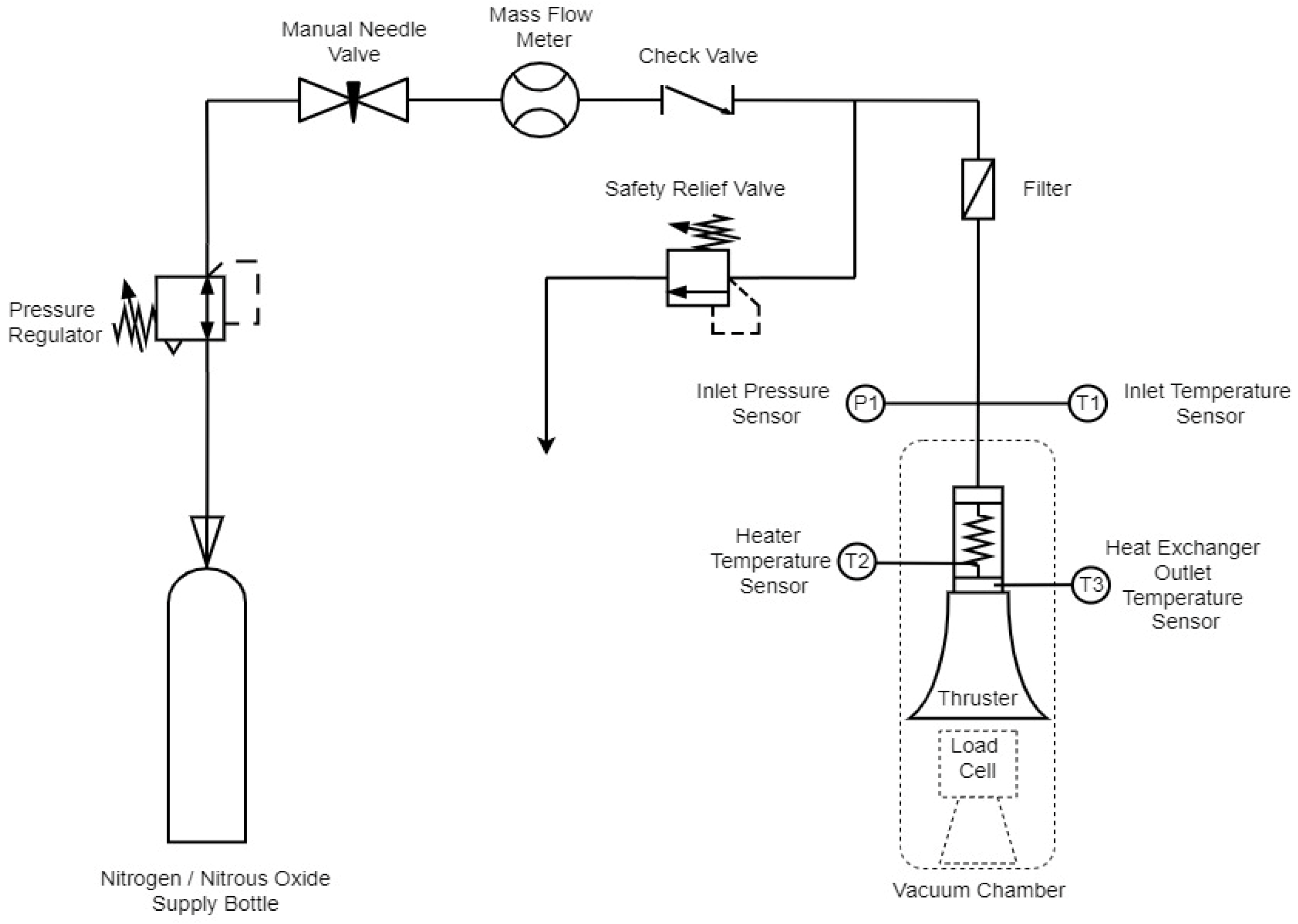
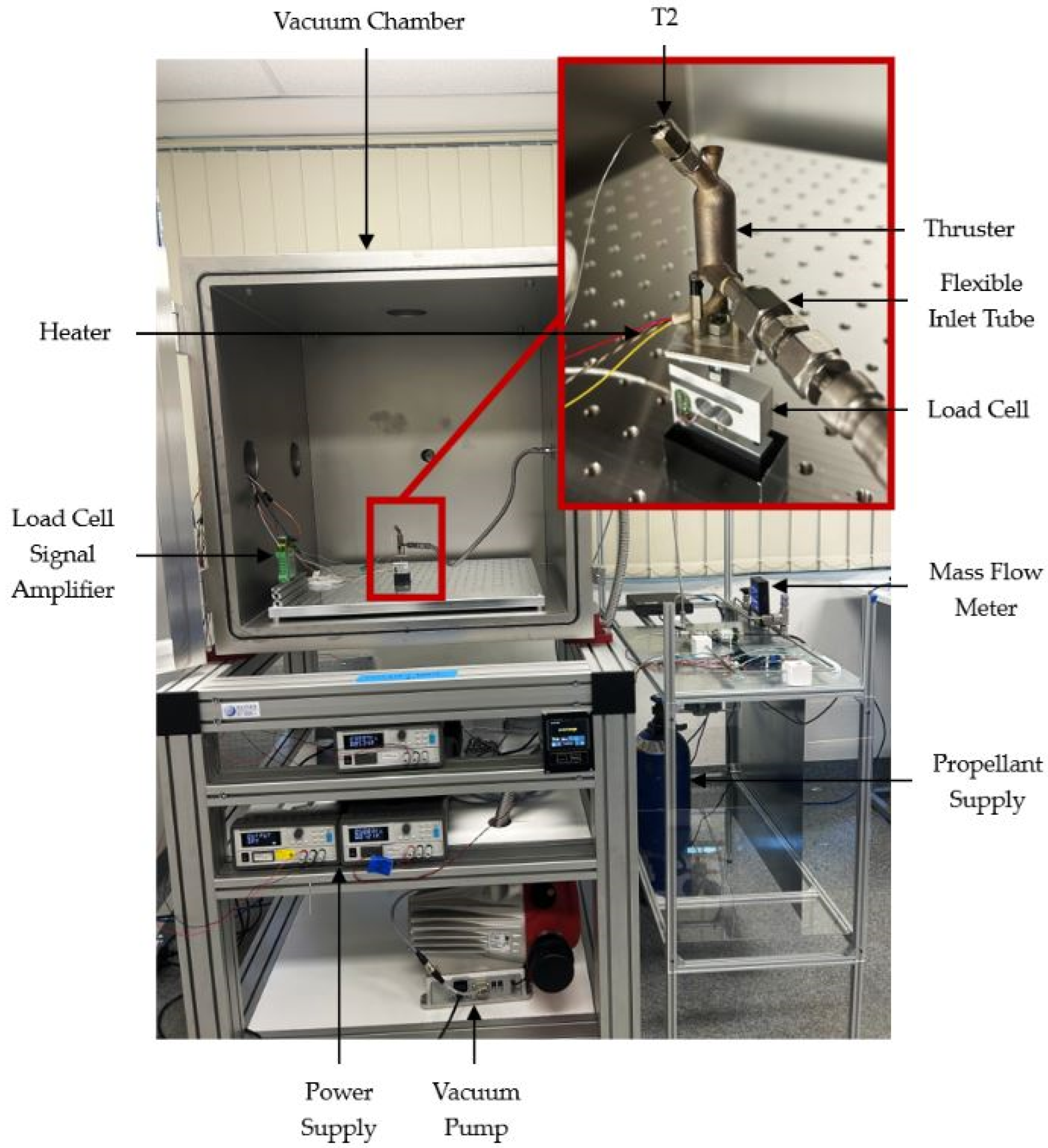
6.1. Experimental Setup

A dedicated portable test bench was designed and assembled to allow for atmospheric and vacuum testing of the resistojet thruster with various propellants. Thermal steady-state testing was conducted in atmospheric conditions with nitrogen as a working fluid to validate the numerical model. The same test bench was then transported next to a vacuum chamber, where the thruster was placed on a load cell for propulsive performance testing using nitrous oxide as the propellant. It should be noted that nitrous oxide’s specific heat capacity is 15% lower than nitrogen, and thus, higher propellant temperatures should be attained. However, its molecular mass is 57% higher, and thus, the specific impulse will be reduced. Figure 12 below depicts the schematic diagram of the test bench configuration.
Full D-size nitrogen and instrument grade nitrous oxide cylinders were utilized for testing. The cylinders were mounted vertically on the test bench so that the fluids were delivered to the thruster in gaseous phase. An Omega 1727A thermal gas mass flow meter, which has a full-scale accuracy of 1%, was utilized for mass flow measurements. The safety relief valve and check valve were incorporated for safety in the event of nitrous oxide decomposition during propulsive testing. P1 and T1 were used to ascertain the fluid inlet conditions before entering the thruster. A Swagelok pressure transducer with a 0–25 MPa range and a 4–20 mA output was utilized for pressure measurement.
The T2 thermocouple was custom built into the cartridge heater in the no-heat generation section, which was performed by the manufacturer to provide a good estimation of the wall temperature that interfaces with the heater. Considerable efforts were made to reduce the thermal resistance between the cartridge heater and wall to decrease the small reduction in temperature between the interfaces. The cartridge heater bore cutout was drilled and then precision reamed to provide a highly accurate sliding fit, and thermal paste was applied at the interface to further reduce the thermal resistance. This thermocouple was assumed to provide an accurate measurement of the wall temperature to replicate the computational boundary condition. Despite the provisions and efforts to reduce the thermal resistance at the interface, minor systematic deviation between the cartridge heater internal temperature and thruster wall temperature is to be expected during the experimental validation of the computational results.
T3 was a 0.5 mm diameter thermocouple to allow for the probe to fit inside the thruster chamber without touching the walls to provide measurement of the propellant temperature after exiting the heat exchanger and before being expelled through the supersonic nozzle. All thermocouples used were type-k thermocouples. An illustration of the cartridge heater and heat exchanger outlet thermocouple locations for testing are illustrated in Figure 13.
A National Instrument USB-6001 data acquisition device was utilized for recording sensor measurements. Power was supplied to the sensors and heater via programmable 30 V DC power supplies. The vacuum chamber used for propulsive testing had a volume of 0.42 m3. A pressure of 460 Pa was attained during testing using a Pfeiffer HiScroll 18 rotary pump. The thruster was fastened to the load cell in the vacuum chamber with insulative spacers to reduce conductive losses and thermal drift of the load cell. The load cell used was a KD40s-5N ultra-miniature force sensor with a 0.1% accuracy class. The sensor was modified and calibrated to be optimized for vacuum conditions. The 0.5 mV/V rated output was amplified by a MAS10 universal strain amplifier to 0–10 V to enhance the measurement resolution. To reduce errors on the thrust measurement from the feedlines, a stainless steel braided flexible tube was used for the inlet. Once the thruster assembly was placed on the load cell, it was recalibrated using precision-slotted masses. Additional precautions were taken by ensuring that the feedline diameter was constant within the vacuum chamber to result in minimal pressure drop of the fluid to reduce its impact on the highly sensitive load cell.
The experimental uncertainties associated with the quantities that were measured directly (temperature, pressure, thrust, and mass flow rate) were taken from calibration certificates and sensor data sheets. For calculated quantities such as the specific impulse and thermal efficiency, the uncertainty of each measurement was incorporated in the calculation through the propagation of uncertainties to give a total uncertainty range. The thruster measurement setup for propulsive performance testing is displayed in Figure 14.

6.2. Experimental Test Cases

Thermal steady-state testing was performed in atmospheric conditions to provide validation of the numerical analysis. The testing was performed for nitrogen mass flow rates of 0.2, 0.25, 0.3, and 0.35 g/s. To achieve the desired mass flow rate for each test, the pressure regulator was manually calibrated before each test. The heater power (measured from the voltage and current draw from the power supply) required to maintain a wall temperature of 373.15 K as per the computational analysis was also calibrated for each mass flow rate prior to conducting the test. Once the calibration of the pressure regulator and heater was completed, the needle valve was opened, and the heater power was supplied simultaneously. The valve was kept open for 400 s to allow for ample time for the thruster to reach thermal steady state, allowing for measurement of the steady-state heat exchanger outlet temperature using T3.
For the propulsive performance testing, the heater power and nitrous oxide mass flow rate were maintained at the design values of 30 Watts and 0.2 g/s, respectively. When the thruster was operated, the heater power was applied before admitting the propellant to increase the solid body temperature and achieve higher propellant temperatures. Warm-up durations of 1 min, 2 min, and 3 min were investigated to comply with the power consumption limitations of the intended satellite bus. To quantify the benefit of the heater and heat exchanger, a reference test was also conducted that involved running the test without the heater to simulate cold gas mode operation. The experimental test cases are listed in Table 4.

7. Results

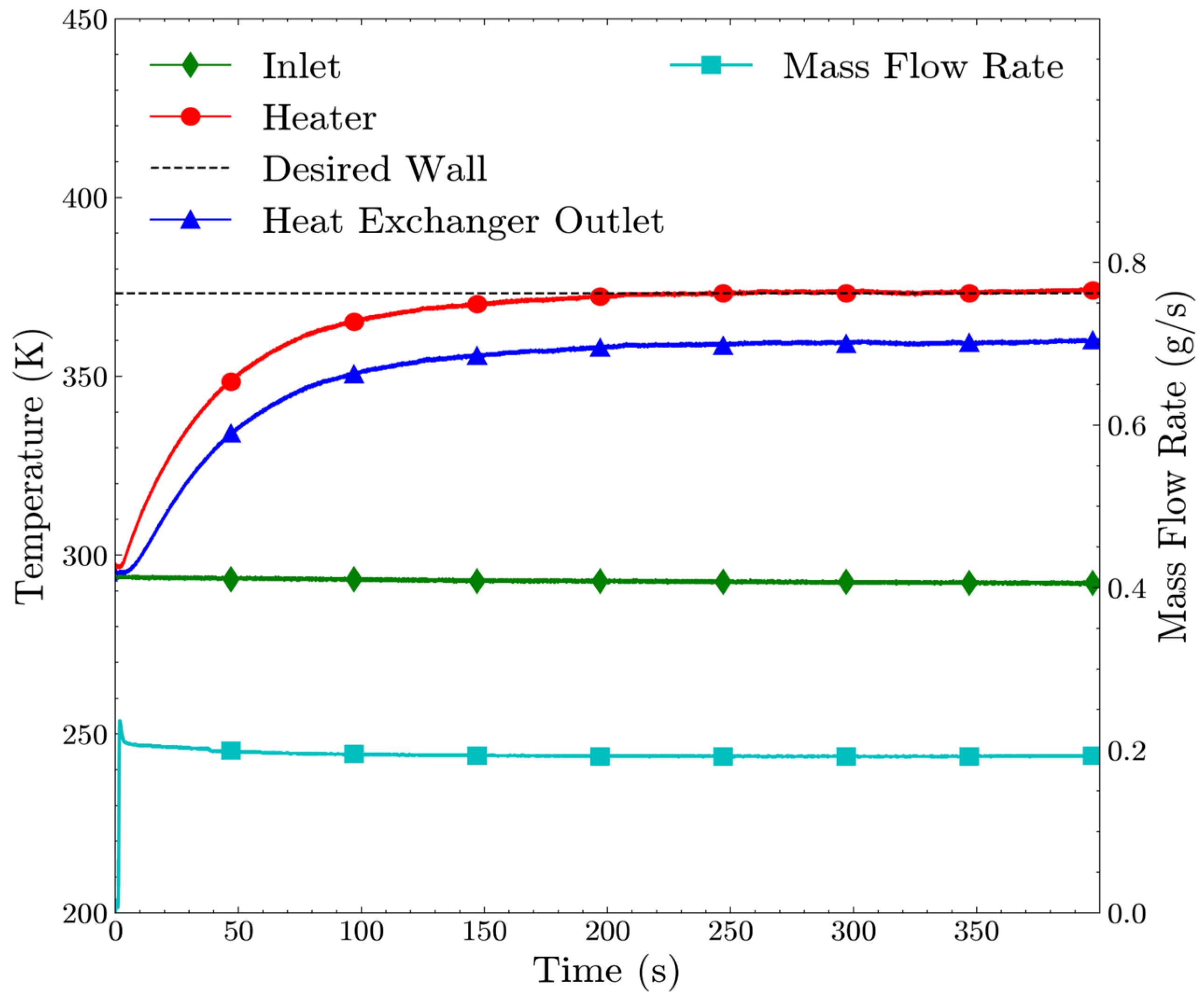
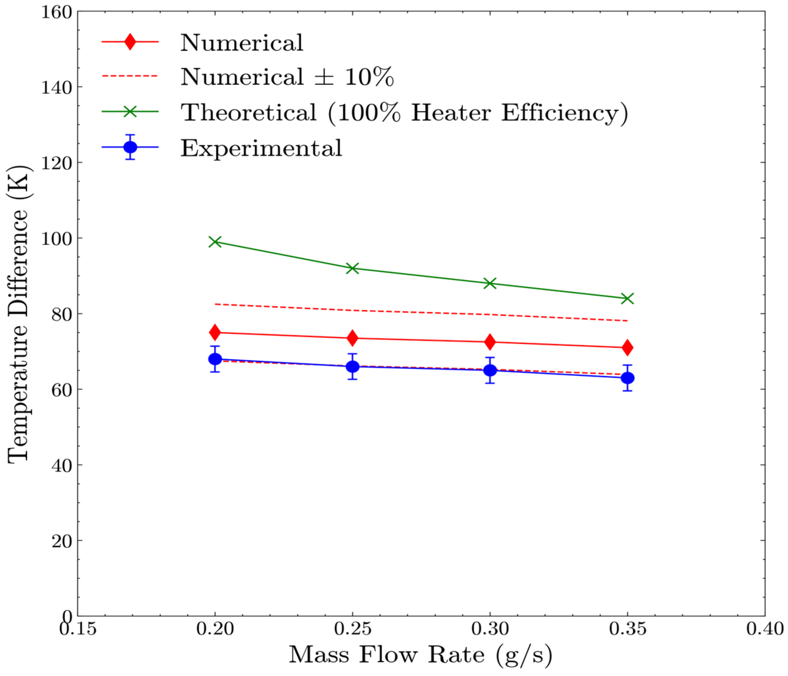
7.1. Computational Model Validation

To validate the computational model—which will be used for further design optimization of the thruster—experimental test cases 1–4 were conducted. The raw experimental results for test case 1 are illustrated in Figure 15, while the results for all steady-state tests are summarized in Figure 16 and compared to the numerical calculations and theoretical predictions assuming 100% heater efficiency. From the raw data, it can be seen that the heater calibration that was conducted before each test was successful in accurately maintaining the desired wall temperature of 373.15 K to replicate the computational boundary condition. The raw data illustrate that steady-state operation is attained within the 400 s test duration, as the measured temperatures remain constant after approximately 200 s. The measured temperature difference across the heat exchanger inlet and outlet was consistently 10% lower than the temperature difference calculated in the numerical model. When taking experimental error into account, the upper bounds of the experimental measurements lie within 6% of the computational results, which demonstrates that the computational model is valid. The systematic error that results in consistently lower temperature differences measured in the experiment is likely due to the assumption that the measured heater temperature is equal to the wall temperature. In actuality, the thermal resistance between the cartridge heater and the wall will result in a small temperature reduction, thus making the experimental wall temperature lower than the wall temperature specified in the computational model. Unfortunately, this thermal resistance was impossible to measure accurately since the cartridge heater was located inside an internal cutout of the heat exchanger and was secured in place with a transition fit, preventing any physical temperature measurements. The measured temperature difference across the heat exchanger was on average 27% lower than the theoretical prediction (assuming 100% heater efficiency), as seen in Figure 16. Therefore, on average, approximately 27% of the heat generated by the heater was lost and not transferred to the propellant. The disparity decreases with an increasing mass flow rate, which is likely due to a reduction in thermal radiation losses associated with the lower operating temperatures.

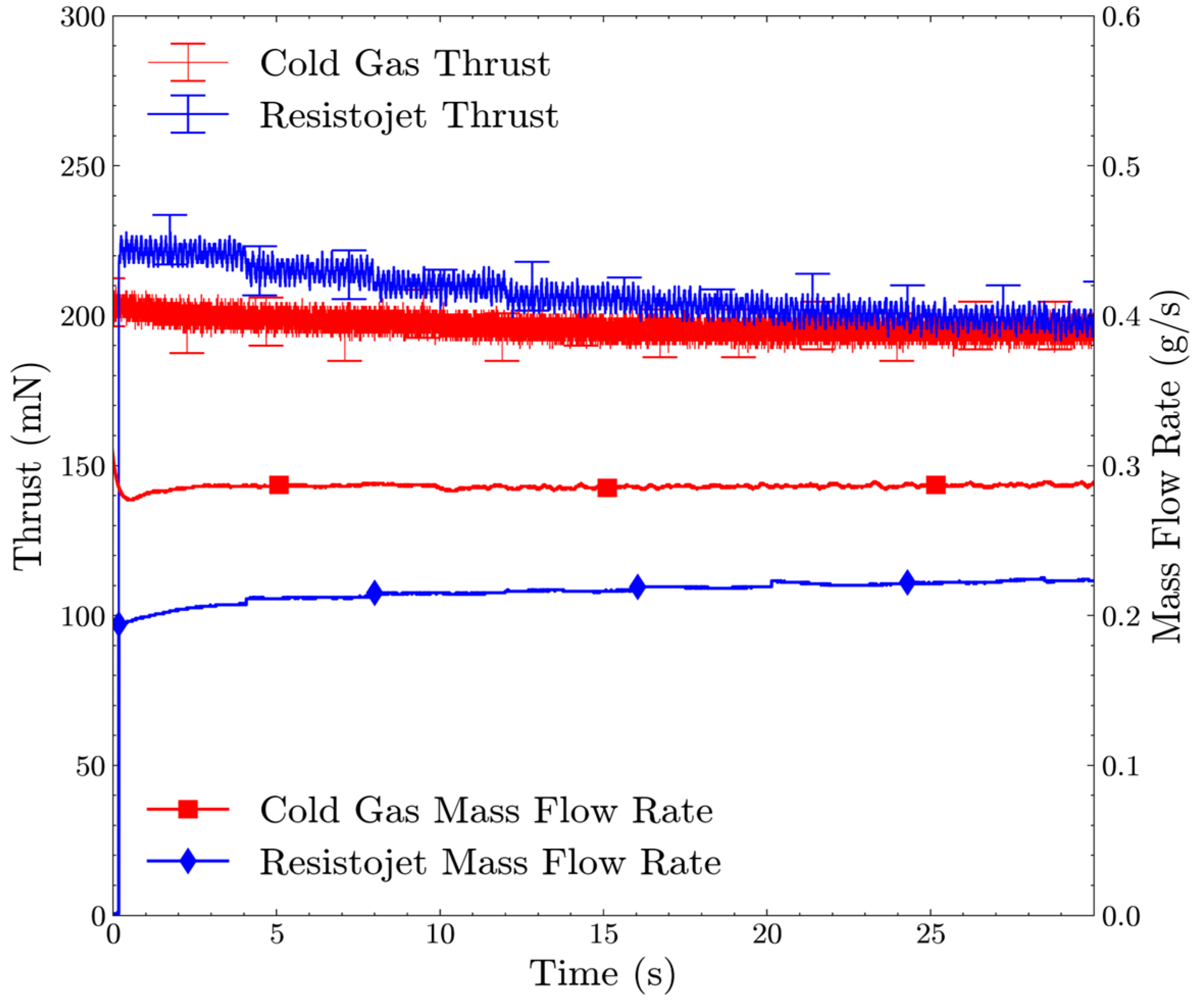
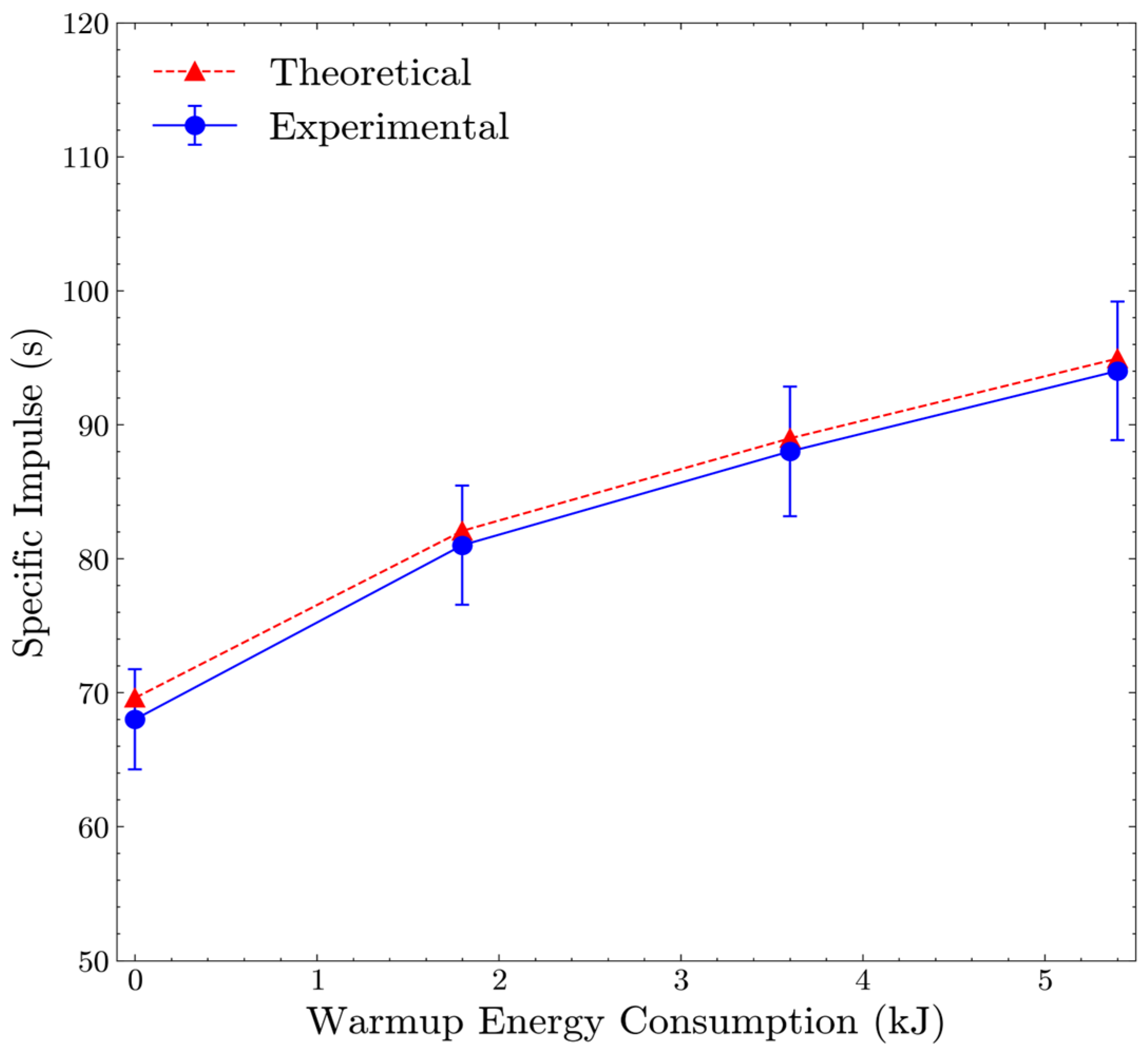
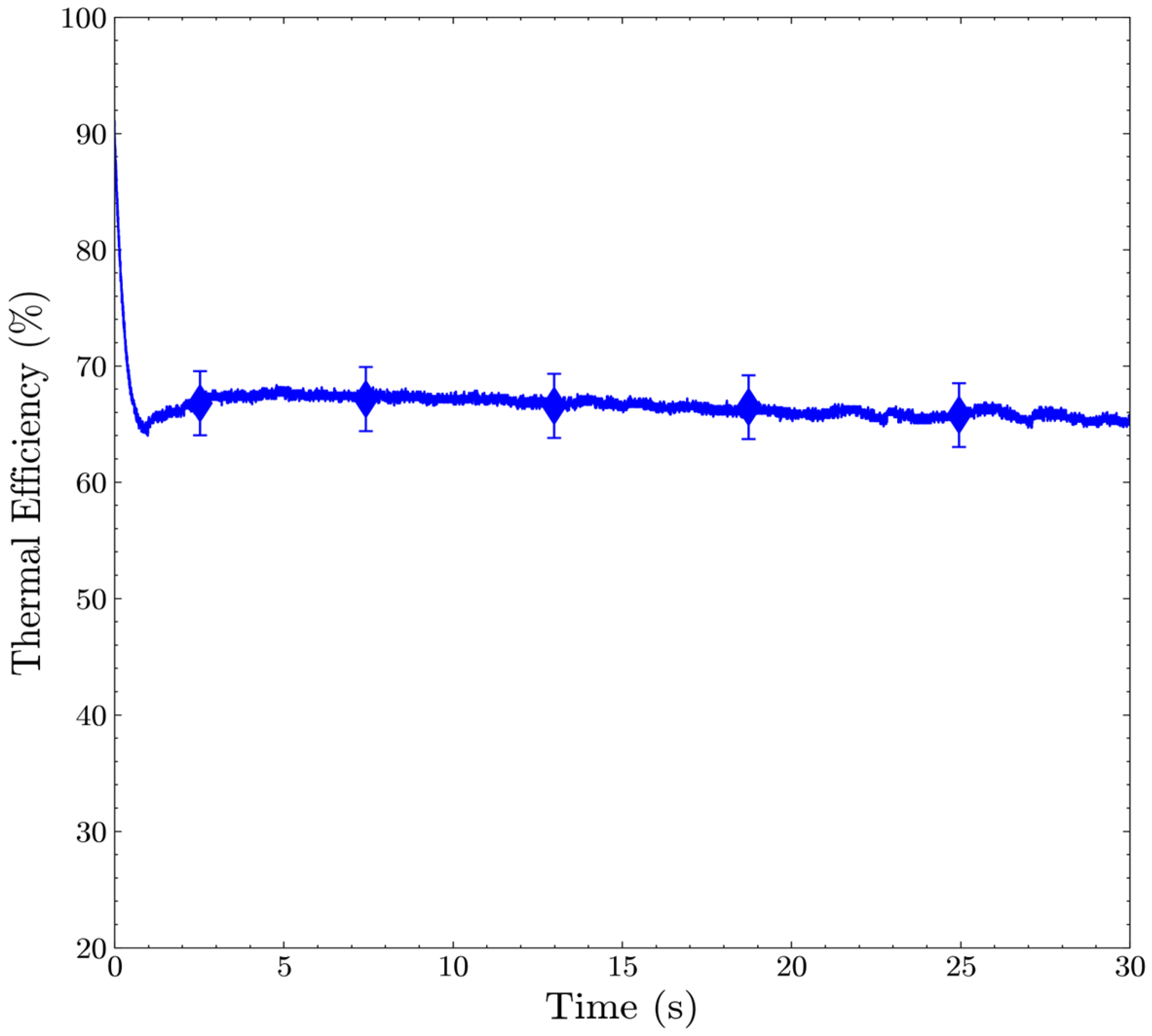
7.2. Propulsive Performance Testing

Propulsive performance testing was undertaken to characterize the resistojet performance and quantify the increase in the specific impulse that is possible with the heater and heat exchanger compared to cold gas mode. From gas dynamics with isentropic flow assumptions, the specific impulse for the thruster can be calculated through the following equation:
I s p = 2 k R T c g k 1 1 P e P c k 1 k
where the heat capacity ratio ( k ) is equal to 1.31; the gravitational constant ( g ) and specific gas constant ( R ) are equal to 9.81 m/s2 and 188.9 J/kgK, respectively; and P e / P c is the nozzle pressure ratio. The specific impulse is shown to be proportional to the square root of the propellant chamber temperature ( T c ). Higher propellant temperatures increase the force imparted by the thruster per unit mass of propellant flow. However, according to gas dynamic theory, the mass flow rate ( m ˙ ) of gas through a supersonic isentropic nozzle can be calculated via the following equation:
m ˙ = A t P c k k R T c 2 k + 1 k + 1 k 1
where A t represents the nozzle throat area for the supersonic nozzle. This expression shows that the mass flow rate is inversely proportional to the square root of the propellant chamber temperature. Therefore, theory suggests that increasing the propellant temperature with the heater and heat exchanger of the resistojet should maintain the same thrust output with a reduced mass flow rate, resulting in an increased specific impulse. The experimental determination of the specific impulse was conducted through the measurement of the thrust force ( F ) and mass flow rate according to Equation (7).
I s p = F m ˙ g
Figure 17 depicts the experimental thrust and mass flow measurements for test cases 7 and 8, which illustrate the theoretical trends and provide a direct comparison between cold gas and resistojet mode. The results indicate that the resistojet mode produces relatively similar thrust output with up to 28% reductions in the mass flow rate, necessitating a relatively short heater warm-up period of 180 s. Throughout the test duration, it can be seen that the cold gas mass flow rate and thrust remains constant, while the resistojet mass flow rate increases with time due to the reduction in the propellant temperature in accordance with Equation (6). Interestingly, the resistojet thrust slightly decreases rather than remaining constant throughout the test as the mass flow rate increases and the subsequent propellant temperature is reduced. This phenomenon was attributed to temperature drift in the highly sensitive load cell sensor since the effect becomes more pronounced with longer warm-up periods of the heater.
The average specific impulse was calculated from the experimental thrust and mass flow rate measurements for test cases 5–8 using Equation (5). The average was taken between 10 and 20 s after the start of the test duration to avoid transient effects. The results are plotted in Figure 18 and compared against the theoretical isentropic specific impulse calculated using the left-hand side of Equation (5) for an expansion ratio of 100. An average experimental propellant chamber temperature between 10 and 20 s was used for the theoretical calculation, therefore allowing for the comparison of the theoretical and experimental specific impulse. Measured chamber temperatures varied from 292 K for the cold gas case to 544 K for the 180 s warm-up case. The measured specific impulse ranged from 0.9–2% less than the theoretical isentropic prediction, signifying that the nozzle losses in the expansion process are minor. The results indicate that operating the low-power 30-Watt heater for short warm-up periods can produce significant improvements in the specific impulse, with the rate of the specific impulse to energy consumption tapering as the heater warm-up period increases. For 5.4 kJ of warm-up energy, the specific impulse was measured at 94 ± 4.8 s, compared to 68 ± 3.5 s for the cold gas reference case, therefore demonstrating a 38% increase in the specific impulse.
The heater efficiency of the thruster was calculated from measured values (see Equation (8)), where T is the measured temperature difference between the inlet and chamber temperature of the propellant and P i n is the measured power input to the heater. Case 6 was selected, as the thruster reached a steady state within the 30 s test firing, with the results illustrated in Figure 19. From the results, it can be seen that the thermal efficiency was measured at 65 ± 2.8% at approximate steady-state conditions 25 s into the firing. It is important to note that the prototype thruster did not have any thermal insulation or radiation shielding for the test campaign undertaken in this work.
η h e a t e r = m ˙ c p T P i n

8. Discussion

The latticed resistojet thruster demonstrated that up to 38% enhancements in the specific impulse compared to cold gas mode with nitrous oxide can be attained with a 30-Watt cartridge heater and a 3 min warm-up period. The thruster was also measured to have a thermal efficiency of 65 ± 2.8% without the application of thermal insulation and radiation shielding. There is only one nitrous oxide resistojet with comprehensive performance data available that can be used to provide comparisons with previous efforts. The resistojet thruster was the result of an extensive development program conducted by SSTL to provide low-cost resistojet technology for the small satellite platform [32]. The thruster flew on the UoSAT-12 spacecraft (325 kg) in 1999, which subsequently became the first and only nitrous oxide resistojet to attain flight heritage [13]. For the on-orbit flight test, the nitrous oxide resistojet thruster produced a thrust of 95 mN and specific impulse of 93 s for a heater power of 91 Watts [33]. The latticed resistojet thruster was measured to achieve a 1% increase in the specific impulse with a 67% reduction in power compared to this thruster in vacuum conditions. During the ground testing of SSTL’s resistojet, the thermal efficiency was measured to be 48% [32]. Thus, the testing of the latticed resistojet thruster demonstrated a 17% improvement in the thermal efficiency.
From a system perspective, the latticed resistojet thruster is highly miniaturized and is manufactured as one piece weighing just 22.4 g. SSTL’s nitrous oxide resistojet that flew on UoSAT-12 comprised six parts, including an outer shell, thermal insulation, an inner shell, a silicon carbide heat exchanger, an injector, and a nozzle assembly, weighing a total of 1.2 kg. The latticed resistojet thruster therefore demonstrates that significant reductions in propulsion system mass and integration complexity are possible due to its highly monolithic and lightweight design. The significant mass and volume savings allow for more mass for the propellant for CubeSats. The subsequent reduction in the propulsion dry mass fraction is particularly influential for improving the Delta-V capability of small satellites and CubeSats, where propulsion dry mass fractions are inherently high [34].

9. Conclusions

The miniaturized latticed resistojet thruster exhibited considerable enhancements in the thermal efficiency and propulsive performance compared to previous nitrous oxide resistojet efforts while permitting significant reductions in system mass. Propulsive testing in a vacuum demonstrated that specific impulses of up to 94 ± 4.8 s were possible when the 30-Watt cartridge heater was turned on three minutes before firing, demonstrating a 38% increase in the specific impulse compared to cold gas mode. A thermal efficiency of 65 ± 2.8% was measured at steady-state conditions. The numerical analysis—which was validated after experimental testing—concluded that the diamond latticed heat exchanger demonstrated superior thermal performance, with 3% and 11% increases in the heat transfer rate compared to the gyroid latticed and helical heat exchangers, respectively. The test measurements and numerical results demonstrate the suitability and advantages for using the latticed resistojet concept for small satellites and CubeSats, where highly miniaturized and thermally efficient heat exchangers are required to conform with strict mass, size, and power constraints.
The manufacturing of the prototype thruster demonstrated what is believed to be the first published results of a TPMS lattice structure that is additively manufactured from GRCop-42. The X-ray computed tomography analysis showed that the internal diamond TPMS lattice structure with a 6 mm unit cell and 0.6 mm minimum wall thickness could be printed via selected laser melting without defects. The high thermal conductivity of GRCop-42 results in significant power savings for CubeSats and small satellites by reducing the warm-up period of the thruster. The testing conducted in this work focused on a highly miniaturized, low-power latticed resistojet concept for the CubeSat platform. However, the maximum operating temperature of GRCop-42 allows for the resistojet thruster concept to be further extended to larger spacecraft propulsion applications, where more power and higher propellant temperatures can be achieved to result in a higher specific impulse. This high-performance variant will be investigated in future testing with the application of thermal insulation and radiation shielding.

10. Patents

A provisional patent has been filed resulting from this work to protect the utilization of TPMS lattice structures as heat exchanger elements for resistojet thrusters and spacecraft propulsion.

Author Contributions

D.T.: resistojet conceptualization, methodology, testing, formal analysis, writing, original draft preparation. P.B. and R.H.: resources, writing, review and editing, supervision, project administration. All authors have read and agreed to the published version of the manuscript.

Funding

This work was supported by the Australian Government Research Training Program Scholarship and receives institutional support from Curtin University.

Data Availability Statement

Data are available for sharing upon request.

Acknowledgments

The authors would like to thank Belinda Godel from the Commonwealth Scientific and Industrial Research Organisation in Perth, Australia, for conducting the CT scan and associated data processing. The authors would also like to thank nTop for providing an educational license to their software for the design of the lattice.

Conflicts of Interest

The authors declare no conflicts of interest.

References

  1. Malphrus, B.K.; Freeman, A.; Staehle, R.; Klesh, A.T.; Walker, R. Interplanetary CubeSat missions. In Cubesat Handbook; Elsevier: Amsterdam, The Netherlands, 2021; pp. 85–121. ISBN 978-0-12-817884-3. [Google Scholar]
  2. Alnaqbi, S.; Darfilal, D.; Swei, S.S.M. Propulsion Technologies for CubeSats: Review. Aerospace 2024, 11, 502. [Google Scholar] [CrossRef]
  3. Powell, S. Industry Update: Prevalence of Nitrous-Based In-Space Propellants. Available online: https://www.dawnaerospace.com/latest-news/prevalence-of-nitrous-based-in-space-propellants (accessed on 12 July 2024).
  4. Chandran, S.; Yli-Opas, P.; Hämäläinen, I.; Peitso, P.; Vilenius, V. Miniaturizing a Resistojet: Design, Analysis and Manufacturing. In Proceedings of the The Space Propulsion Conference, Estoril, Portugal, 17–19 March 2020. [Google Scholar]
  5. Lemmer, K. Propulsion for CubeSats. Acta Astronaut. 2017, 134, 231–243. [Google Scholar] [CrossRef]
  6. Zakirov, V.; Sweeting, M.; Lawrence, T.; Sellers, J. Nitrous oxide as a rocket propellant. Acta Astronaut. 2001, 48, 353–362. [Google Scholar] [CrossRef]
  7. Rovey, J.L.; Lyne, C.T.; Mundahl, A.J.; Rasmont, N.; Glascock, M.S.; Wainwright, M.J.; Berg, S.P. Review of multimode space propulsion. Prog. Aerosp. Sci. 2020, 118, 100627. [Google Scholar] [CrossRef]
  8. NASA LunaH-Map Mission. Available online: https://blogs.nasa.gov/lunah-map/ (accessed on 10 December 2023).
  9. Smith, C.; Cheek, N.; Burnside, C.; Baker, J.; Adell, P.; Picha, F.; Kowalkowski, M.; Lightsey, G. The Journey of the Lunar Flashlight Propulsion System from Launch through End of Mission. In Proceedings of the 37th Annual Small Satellite Conference, SSC23-VI-03, Logan, UT, USA, 26 July 2023. [Google Scholar]
  10. Lauck, F.; Werling, L.; Dobusch, J.; Gritzka, M.; Stratmann, V.; Merz, F.; Hã, T. From Lampoldshausen to Orbit: DLR Spin-off GreenDelta and the Development Status of Green Propellant Thrusters Based on H2O2 and N2O. In Proceedings of the 37th Annual Small Satellite Conference, SSC23-VI-07, Logan, UT, USA, 5–10 August 2023. [Google Scholar]
  11. Walton, M. Introducing Resistojet Thruster Technology. May 2022. [Benchmark Space Systems]. Available online: https://www.benchmarkspacesystems.com/news/post/benchmark-introduces-resistojet-thruster-technology (accessed on 31 July 2024).
  12. Mirtich, M. Resistojet Propulsion for Large Spacecraft Systems; NASA Technical Memorandum; Lewis Research Center: Cleveland, OH, USA, 1982.
  13. Gibbon, D.; Baker, A.; Coxhill, I.; Sweeting, M. The Development of a Family of Resistojet Thruster Propulsion Systems for Small Spacecraft. In Proceedings of the 17th Annual AIAA/USU Conference on Small Satellites, Logan, UT, USA, 11–14 August 2003. [Google Scholar]
  14. Lawrence, T. Research into Resistojet Rockets for Small Satellite Applications. Ph.D. Thesis, University of Surrey, Surrey, UK, 1998. [Google Scholar]
  15. Romei, F.; Grubišić, A.N. Validation of an additively manufactured resistojet through experimental and computational analysis. Acta Astronaut. 2020, 167, 14–22. [Google Scholar] [CrossRef]
  16. Nakata, D.; Kinefuchi, K. Thermal Design and Experimental Verification of the 3D-printed Registojet. In Proceedings of the 2018 Joint Propulsion Conference, Cincinnati, OH, USA, 9–11 July 2018; American Institute of Aeronautics and Astronautics: Reston, VA, USA, 2018. [Google Scholar] [CrossRef]
  17. Evans, A.G.; Hutchinson, J.W.; Fleck, N.A.; Ashby, M.F.; Wadley, H.N.G. The topological design of multifunctional cellular metals. Prog. Mater. Sci. 2001, 46, 309–327. [Google Scholar] [CrossRef]
  18. Pan, C.; Han, Y.; Lu, J. Design and Optimization of Lattice Structures: A Review. Appl. Sci. 2020, 10, 6374. [Google Scholar] [CrossRef]
  19. Sokollu, B.; Gulcan, O.; Konukseven, E.I. Mechanical properties comparison of strut-based and triply periodic minimal surface lattice structures produced by electron beam melting. Addit. Manuf. 2022, 60, 103199. [Google Scholar] [CrossRef]
  20. Dutkowski, K.; Kruzel, M.; Rokosz, K. Review of the State-of-the-Art Uses of Minimal Surfaces in Heat Transfer. Energies 2022, 15, 7994. [Google Scholar] [CrossRef]
  21. Maconachie, T.; Leary, M.; Lozanovski, B.; Zhang, X.; Qian, M.; Faruque, O.; Brandt, M. SLM lattice structures: Properties, performance, applications and challenges. Mater. Des. 2019, 183, 108137. [Google Scholar] [CrossRef]
  22. Kaur, I.; Singh, P. State-of-the-art in heat exchanger additive manufacturing. Int. J. Heat Mass Transf. 2021, 178, 121600. [Google Scholar] [CrossRef]
  23. Kaur, I.; Singh, P. Critical evaluation of additively manufactured metal lattices for viability in advanced heat exchangers. Int. J. Heat Mass Transf. 2021, 168, 120858. [Google Scholar] [CrossRef]
  24. Mahmoud, D.; Tandel, S.R.S.; Yakout, M.; Elbestawi, M.; Mattiello, F.; Paradiso, S.; Ching, C.; Zaher, M.; Abdelnabi, M. Enhancement of heat exchanger performance using additive manufacturing of gyroid lattice structures. Int. J. Adv. Manuf. Technol. 2023, 126, 4021–4036. [Google Scholar] [CrossRef]
  25. Li, W.; Yu, G.; Yu, Z. Bioinspired heat exchangers based on triply periodic minimal surfaces for supercritical CO2 cycles. Appl. Therm. Eng. 2020, 179, 115686. [Google Scholar] [CrossRef]
  26. Tang, W.; Zhou, H.; Zeng, Y.; Yan, M.; Jiang, C.; Yang, P.; Li, Q.; Li, Z.; Fu, J.; Huang, Y.; et al. Analysis on the convective heat transfer process and performance evaluation of Triply Periodic Minimal Surface (TPMS) based on Diamond, Gyroid and Iwp. Int. J. Heat Mass Transf. 2023, 201, 123642. [Google Scholar] [CrossRef]
  27. Dixit, T.; Al-Hajri, E.; Paul, M.C.; Nithiarasu, P.; Kumar, S. High performance, microarchitected, compact heat exchanger enabled by 3D printing. Appl. Therm. Eng. 2022, 210, 118339. [Google Scholar] [CrossRef]
  28. Romei, F. High Temperature Resistojets for All-Electric Spacecraft. Ph.D. Thesis, University of Southampton, Faculty of Engineering and Physical Sciences, Southampton, UK, 2019. [Google Scholar]
  29. Mankavi, F.; Rezaeiha, A. Design and Development of a Low Power Laboratory Resistojet. In Proceedings of the AJCPP2012, Xi’an, China, 1–4 March 2012. [Google Scholar]
  30. Samson, S.; Tran, P.; Marzocca, P. Design and modelling of porous gyroid heatsinks: Influences of cell size, porosity and material variation. Appl. Therm. Eng. 2023, 235, 121296. [Google Scholar] [CrossRef]
  31. Gradl, P.R.; Protz, C.S.; Cooper, K.; Ellis, D.; Evans, L.J.; Garcia, C. GRCop-42 Development and Hot-fire Testing Using Additive Manufacturing Powder Bed Fusion for Channel-cooled Combustion Chambers. In Proceedings of the AIAA Propulsion and Energy 2019 Forum, Indianapolis, IN, USA, 19–22 August 2019; American Institute of Aeronautics and Astronautics: Reston, VA, USA, 2019. [Google Scholar]
  32. Lawrence, T.J.; Sweeting, M.; Paul, M.; Sellers, J.J.; LeDuc, J.R. Performance Testing of a Resistojet Thruster for Small Satellite Applications; Air Force Research Laboratory California: Boron, CA, USA, 1998. [Google Scholar]
  33. Sweeting, M.N.; Lawrence, T.; Leduc, J. Low-cost orbit manoeuvres for minisatellites using novel resistojet thrusters. Proc. Inst. Mech. Eng. Part G J. Aerosp. Eng. 1999, 213, 223–231. [Google Scholar] [CrossRef]
  34. Zakirov, V.; Sweeting, M.; Erichsen, P.; Lawrence, T. Specifics of Small Satellite Propulsion: Part 1. In Proceedings of the 15th AIAA/USU Conference on Small Satellites, SSC01-XI-6, Logan, Utah, 13–16 August 2001. [Google Scholar]
Figure 1. Lattice unit cell topologies. From left to right: BCC; FCC; gyroid; and diamond.
Aerospace 11 00714 g001
Figure 2. Resistojet thruster concept illustrating the thruster valve, centrally located cartridge heater, internal heat exchanger, and supersonic nozzle.
Aerospace 11 00714 g002
Figure 3. The section view of the resistojet thruster concept (left) and internal diamond TPMS heat exchanger (right).
Aerospace 11 00714 g003
Figure 4. The four resistojet heat exchanger solid geometry concepts investigated in the numerical analysis. The concepts are in numerical order from left to right.
Aerospace 11 00714 g004
Figure 5. Fluid mesh for heat exchanger Concepts 1, 2, 3, and 4 in order from left to right. The total number of cells in the fluid and solid domains for each concept was 229,685, 243,119, 3,483,985, and 3,692,463, respectively.
Aerospace 11 00714 g005
Figure 6. A comparison of the areal heat transfer coefficient (hA) calculated in the numerical analysis for each heat exchanger concept with respect to the mass flow rate of nitrogen gas.
Aerospace 11 00714 g006
Figure 7. A comparison of the heat transfer rate calculated in the numerical analysis from the heater and heat exchanger to the working fluid for each design concept with respect to the mass flow rate.
Aerospace 11 00714 g007
Figure 8. The cross-sectional view of the temperature distribution for the diamond TPMS latticed resistojet heat exchanger (Concept 4) for a nitrogen mass flow rate of 0.2 g/s. The temperature distribution shows the bulk propellant temperature closely approaching the solid wall temperature at the heat exchanger outlet.
Aerospace 11 00714 g008
Figure 9. Additively manufactured GRCop-42 thrusters with the internal diamond TPMS heat exchanger. The thruster used for testing is shown on the left while the thruster used for the manufacturing analysis is shown on the right.
Aerospace 11 00714 g009
Figure 10. Cross-sectional images of the XCT scan results illustrating the internal lattice structure.
Aerospace 11 00714 g010
Figure 11. A photo of the GRCop-42 resistojet with an internal lattice structure after being cut in half next to an Australian 1 dollar coin for scale (25 mm in diameter).
Aerospace 11 00714 g011
Figure 12. The schematic of the test bench displaying the setup for atmospheric thermal steady-state testing with nitrogen and propulsive performance testing with nitrous oxide (which included additional facilities and instrumentation shown in dotted lines).
Aerospace 11 00714 g012
Figure 13. An illustration of the thermocouple locations used for measuring the wall temperature at the interface with the heater and the heat exchanger outlet temperature.
Aerospace 11 00714 g013
Figure 14. A photo of the test bench and vacuum chamber used for propulsive performance testing.
Aerospace 11 00714 g014
Figure 15. Raw experimental measurements of the propellant inlet temperature, heat exchanger outlet temperature, and wall temperature for a nitrogen mass flow rate of 0.2 g/s.
Aerospace 11 00714 g015
Figure 16. An illustration of the disparity between the experimental measurements and numerical and theoretical calculated results for four mass flow rates. The difference in temperature between the heat exchanger inlet and outlet is plotted, with dashed lines to represent ± 10% deviations from the numerical calculation.
Aerospace 11 00714 g016
Figure 17. Thrust and mass flow measurements for test cases 7 and 8, demonstrating the significant reduction in the mass flow rate required to achieve a 200 mN thrust output for the resistojet compared to cold gas.
Aerospace 11 00714 g017
Figure 18. A comparison of the theoretical isentropic specific impulse (calculated using the measured propellant chamber temperature) and the average measured specific impulse for test cases 5–9.
Aerospace 11 00714 g018
Figure 19. Heat transfer efficiency measurements for test case 6, where a thermal steady state was achieved within the 30 s test duration.
Aerospace 11 00714 g019
Table 1. Nitrous oxide resistojet targeted operating parameters calculated from isentropic flow assumptions.
Thruster ParameterTarget Value
Chamber Pressure400 kPa
Mass Flow Rate0.2 g/s
Throat Diameter0.6 mm
Expansion Ratio100
Table 2. GRCop-42 material properties used for the numerical analysis.
Material PropertyValue
Thermal Conductivity280 W/mK
Specific Heat Capacity385 J/kgK
Density8790 kg/m3
Table 3. Boundary conditions used for the CHT analysis.
Boundary ConditionBoundary Type Specification
InletMass flow0.2–0.35 g/s; 293 K
OutletOutflowNA
HeaterConstant temperature373.15 K
External surfaceRadiationε = 0.6; ambient = 293 K
Table 4. A list of the test cases investigated during the experiments.
PurposeTest CaseFluidMass Flow Rate (g/s)Heater Power (W)
[Volts, Amps]
Heater Warm-up Time (s)Firing
Duration (s)
Computational Validation1Nitrogen0.2021.4
[19.8, 1.08]
0400
2Nitrogen0.2524.2
[21.0, 1.15]
0400
3Nitrogen0.3027.6
[22.6, 1.22]
0400
4Nitrogen0.3531.0
[24, 1.29]
0400
Propulsive
Performance Evaluation
5Nitrous
Oxide
0.2030
[24, 1.25]
6030
6Nitrous
Oxide
0.2030
[24, 1.25]
12030
7Nitrous
Oxide
0.2030
[24, 1.25]
18030
Cold Gas Mode
Reference
8Nitrous
Oxide
0.200NA30
Disclaimer/Publisher’s Note: The statements, opinions and data contained in all publications are solely those of the individual author(s) and contributor(s) and not of MDPI and/or the editor(s). MDPI and/or the editor(s) disclaim responsibility for any injury to people or property resulting from any ideas, methods, instructions or products referred to in the content.

