Article

Study on the Improvement of Theoretical and Electric Field Simulation Methods for the Accurate Prediction of FEEP Thruster Performance

1
Sejong University, Seoul 05006, Republic of Korea
2
LIG Nex1, Yongin 16911, Republic of Korea
3
SOLETOP, Daejeon 34051, Republic of Korea
4
Sungkyunkwan University, Suwon 03063, Republic of Korea
*
Author to whom correspondence should be addressed.
Aerospace 2024, 11(9), 716; https://doi.org/10.3390/aerospace11090716
Submission received: 24 July 2024 / Revised: 20 August 2024 / Accepted: 27 August 2024 / Published: 2 September 2024
(This article belongs to the Special Issue Space Propulsion: Advances and Challenges (2nd Edition))

Abstract

:
In this study, we investigate and propose an improved theoretical method to more accurately predict the performance of a field-emission electric propulsion (FEEP) thruster with its complex configuration. We identify critical flaws in the previous theoretical methods and derive corrected equations. Additionally, we define and implement the overall half angle of the Taylor cone to account for variations in the Taylor cone’s half angle depending on the applied voltage. Next, we also establish an improved method of the electric filed simulation in a three-dimensional domain to accurately predict a trajectory of extracted ions and a resulting spatial beam distribution of the FEEP thruster by incorporating a configuration of the Taylor cone with the estimated overall half angle from the results of the present theoretical method. Through comparison with the experimental measurements, we found that the present improved methods for theoretical and electric field simulations can yield more accurate predictions than those of the previous methods, especially for higher V and Iem regimes, which correspond to the actual operating conditions of the FEEP thruster. Consequently, we anticipate that the proposed methods can enhance the reliability and efficiency of the design process by accurately predicting performance when developing the new FEEP thruster with its non-symmetric complex configuration to match specific thrust or spatial beam requirements.

1. Introduction

As CubeSat missions become increasingly complex and diverse, various space propulsion technologies for CubeSat applications have shown significant advancements in recent years [1]. Space propulsion technologies for CubeSats can generally be divided into two categories: chemical and electric types. Among these technologies, field-emission electric propulsion (FEEP) is a type of electrostatic electric propulsion that generates thrust by extracting and accelerating ions through a field evaporation mechanism, which results from the interaction between induced electric force and surface tension of a liquid metal propellant. During the last decade, FEEP technology has received considerable attention due to its specialized advantages for CubeSat applications, such as simplicity, miniaturization, compactness, lightweight, high efficiency, and long operational time [1].
FEEP technology was initially studied in the United States in the 1960s and has been further developed mainly by a few European research groups since the 1970s. It has been particularly focused on scientific satellite missions requiring very low thrust for precise attitude control and drag compensation. For example, researchers at Centrospazio (Electric Propulsion Laboratory) at the University of Pisa in Italy played a major role in developing FEEP technology using a cesium liquid metal propellant and a slit-type emitter during the 1990s and early 2000s [2,3,4,5]. Centrospazio developed the FEEP-5 and FEEP-50 thrusters, which can produce thrusts of 0.04 mN and 1.4 mN, respectively, with a specific impulse of 9000 s. In the 2000s, Centrospazio, in collaboration with the private company Alta, developed the first prototype of the FEEP thruster specifically designed for the Laser Interferometer Space Antenna (LISA) Pathfinder mission funded by the European Space Agency (ESA). This FT-150 FEEP prototype system utilized cesium as a propellant and a slit emitter to generate thrust ranging from 0.1 to 150 μN. However, this system was not selected for the LISA Pathfinder mission because of its unavailability within the required timeframe [6]. During a similar time period, the Austrian Research Center (ARC) and its spin-out company, FOTEC, developed a new type of FEEP system using indium as a liquid metal ion source (LMIS) in the late 1980s [7]. In the 2000s, they developed a crown-type emitter consisting of several porous needles to produce thrust in the range of 100 μN to 1 mN. As a result, their prototype successfully achieved a maximum thrust of 1 mN with a high specific impulse greater than 6000 s at a power-to-thrust ratio below 80 W/mN [8]. Based on this technology, the Austrian spin-out company ENPULSION further developed and commercialized the IFM NANO product series in 2018 for the first time. By the end of 2023, more than 185 FEEP products had been launched into space on 79 different spacecraft worldwide [9]. Meanwhile, working for ARC in the early years of the 21st century, Tajmar conducted significant fundamental research on FEEP technology, developing and proposing several theoretical methods based on experimental measurements [10,11,12]. After moving to TU Dresden in Germany, he developed a highly miniaturized FEEP system called NanoFEEP, which used a single emitter and gallium propellant instead of indium. NanoFEEP was capable of producing a continuous thrust of less than 10 μN and demonstrated its performance in orbit by being integrated as the main propulsion module of the one unit (1U) CubeSat, UWE-4 [13].
However, through extensive literature reviews, the authors identified some critical flaws in the previous theoretical methods for the FEEP thruster that limit their applicability to the actual operating conditions of the thruster. As a result, the authors found that the accuracy of these methods drastically decreased when designing and predicting the actual performance of the FEEP thruster. Therefore, the objective of the present study is to investigate and develop improved methods for theoretical and electric field simulations to predict the actual performance of the FEEP thruster more accurately with its complex configuration during its design stage. To achieve this, we first summarize the previous theoretical methods and their flaws and then derive corrected equations. Next, we verify our method by comparing its results with experimental measurements and the previous theoretical method to confirm improvements in accuracy and applicability to the actual operating conditions of the FEEP thruster. Finally, we propose an improved electric simulation method incorporating the outcomes of the present corrected theoretical method to accurately predict the trajectory of extracted ions and the resulting spatial beam distribution of the FEEP thruster in a three-dimensional domain. Also, we verify that this improved electric simulation method can yield more accurate results for the FEEP thruster. Consequently, we anticipate further enhancements in the reliability and efficiency of the design process through this study when developing a new FEEP thruster with its non-symmetric complex configuration to match specific thrust or spatial beam requirements.

2. Principle and Theoretical Methods of FEEP Thruster

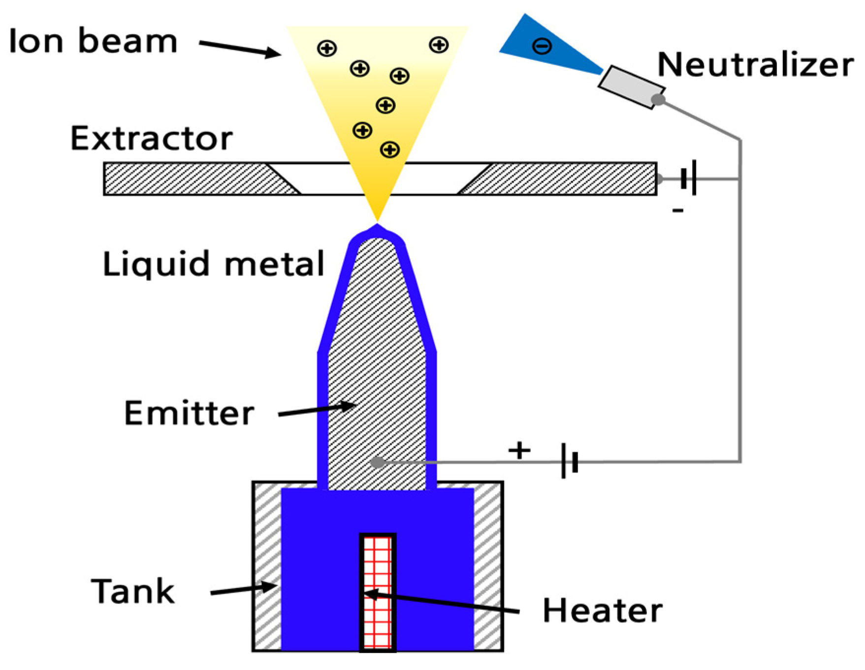
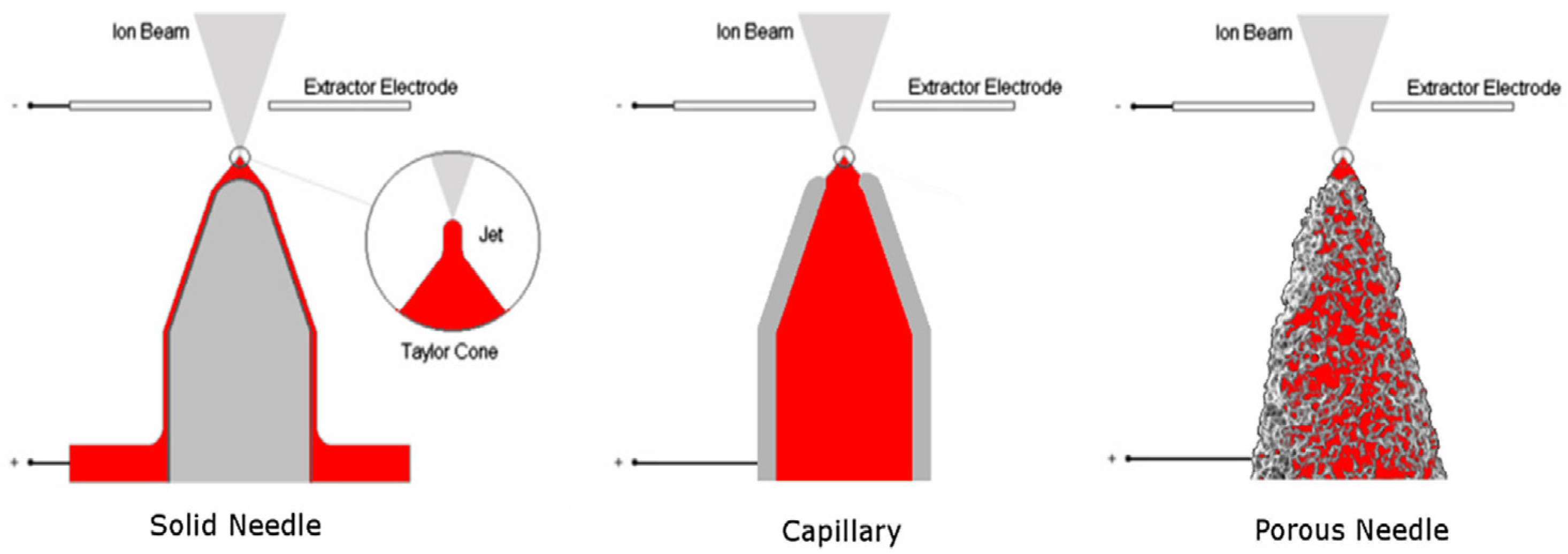
2.1. Working Principle

The field-emission electric propulsion (FEEP) thruster is a type of electrostatic propulsion that uses a liquid metal (such as cesium, indium, or gallium) as a propellant, and its schematic is depicted in Figure 1. When a high potential difference is applied between the emitter and an extraction electrode (extractor) and a liquid metal is supplied through a positively charged emitter by capillary force, a Taylor cone is formed at the tip of the emitter because of the interplay of the surface tension of the liquid metal propellant and electric field forces, as illustrated in Figure 2 [14,15]. Depending on the wetting and supply methods of the liquid metal propellant, the emitter configurations are conventionally categorized into a narrow capillary tube, a sharp solid needle, and a porous needle, as shown in Figure 3 [16]. In addition, the emission of the FEEP thruster can be divided into three modes depending on the strength of the emission current (Iem) and the applied voltage (V) [17]. In low Iem and V regimes, a liquid metal propellant begins to ionize, and its lightweight ions are ejected with high velocities through the accelerator from the Taylor cone surface when the electric field strength exceeds approximately 109 V/m. This is an ion emission-only mode (i.e., a pure ionic emission mode), where the thrust force of the FEEP thruster is generated by the acceleration of field evaporated ions into an exhaust beam. As Iem and V increase, a small number of droplets begin to separate and emit from the Taylor cone surface because of the increased electric field strength, causing a transition mode from a pure ion emission to an emission of ion and droplet mixture. When Iem and V exceed a certain threshold, droplet emission becomes significant, resulting in an emission mode of ion and droplet mixture. Although the Taylor cone plays an important role in extracting and ejecting ions from the emitter, we found that its detailed geometrical information has not been reflected in theoretical or simulation methods because of its very tiny size and difficulties in convergence of numerical calculations. For simplicity, only the emitter configuration is usually modeled without the Taylor cone, and ion extraction and ejection are assumed to occur directly from the emitter tip surface.

2.2. Previous Theoretical Methods

Since the 1980s, several theoretical methods have been proposed to explain the field evaporation relations between Iem and V for various emitter shapes. Here, two major theoretical methods are summarized. First, Mair defined Iem as Equations (1)–(3) for a capillary emitter when V is of a similar order to an extinction voltage (V0x), which is V / V 0 x 1 1 [18].
I e m = 3 π 2 q m e R γ cos α T 2 V 0 x V   V 0 x   1 ,    V / V 0 x 1 1
V 0 x = 2 k R γ cos α T ε 0
ln 2 d R < k < ln 4 d R
Here, ε 0 is a vacuum permittivity, k is a numerical constant, and d is the distance between the emitter tip and the extraction electrode. Also, as illustrated in Figure 4a, R is the inner radius of a capillary emitter, α T is a Taylor cone half angle, and γ is the surface tension of a liquid metal [18]. Meanwhile, Prof. Tajmar [11] derived a similar theoretical relation between Iem and V for a needle emitter, as shown in Figure 4b, using Equations (4)–(6) based on Mair’s method.
I e m = 3 π 2 q m e r b a s e γ cos α T 2 V 0 V   V 0   1 ,    V / V 0 x 1 1
V 0 = ln 2 d r b a s e γ r b a s e ε 0
r b a s e = R e m cos α T
Here, V0 is an onset or starting voltage that starts to extract ions from the Taylor cone, and rbase is a Taylor cone base radius, which is defined as a function of an emitter tip radius (Rem) and α T [11,12]. We found that in Equation (4), R in Equation (1) was simply replaced with rbase to be used for a needle emitter.
To verify whether the previous methods are valid, we compared the theoretical results with experimental measurements. For example, in the case of a needle emitter, Tajmar’s theoretical results with α T = 49.3 ° showed relatively good agreement with experiments in Ref. [11], especially at lower ranges of V and Iem, less than approximately 3000 V and 50 μA, respectively, as depicted in Figure 5. However, it was observed that deviations between Tajmar’s theoretical result and experimental measurements became larger as V and Iem increased, resulting in lower accuracy of the theoretical method, especially within the nominal operating ranges of the actual FEEP thruster.
Thus, we conclude that identifying the reasons for these deviations and investigating potential modifications is necessary for the efficient development of the FEEP thruster by further improving the accuracy of the theoretical method.

3. Improved Theoretical Method

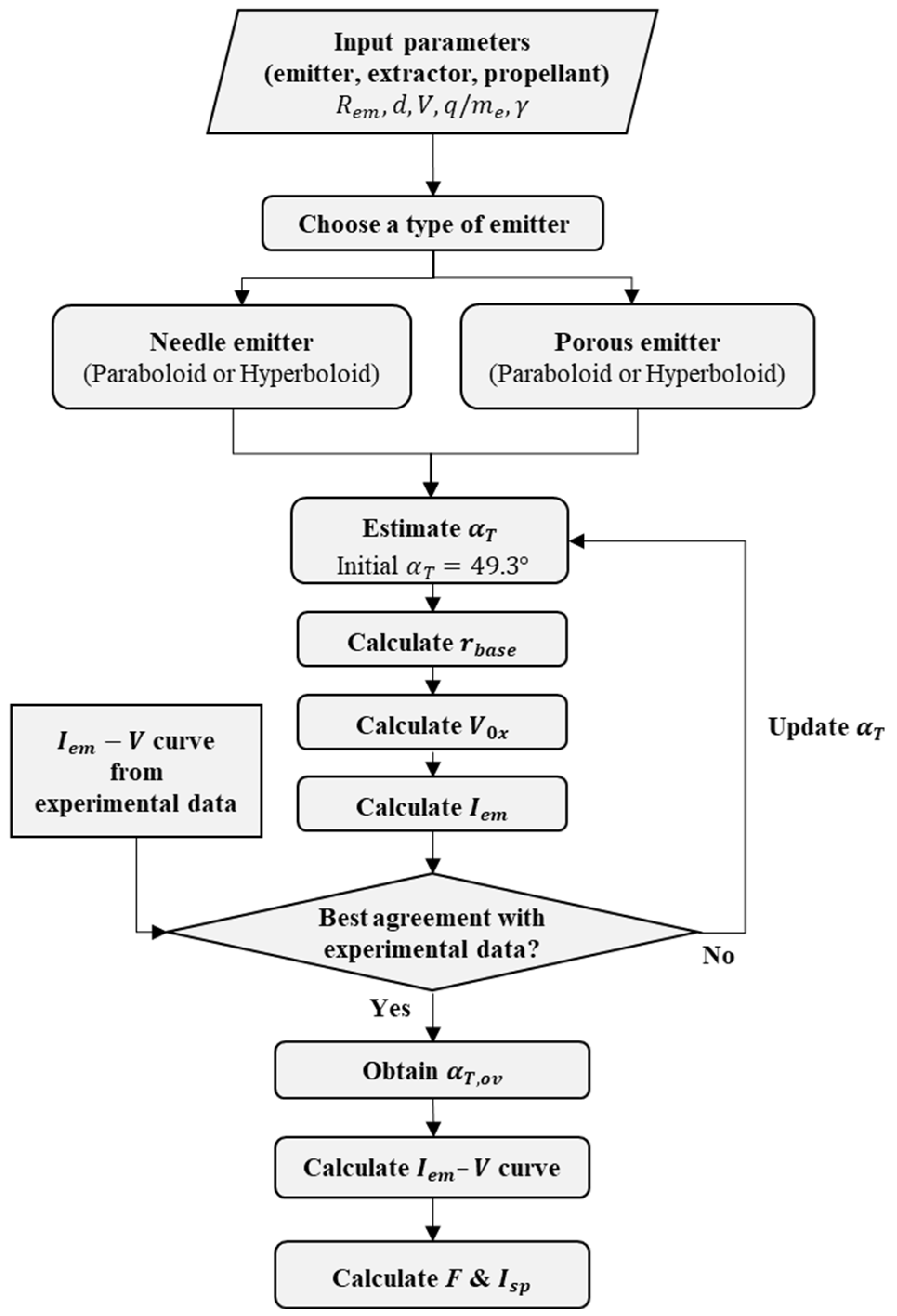
3.1. Overview and Method
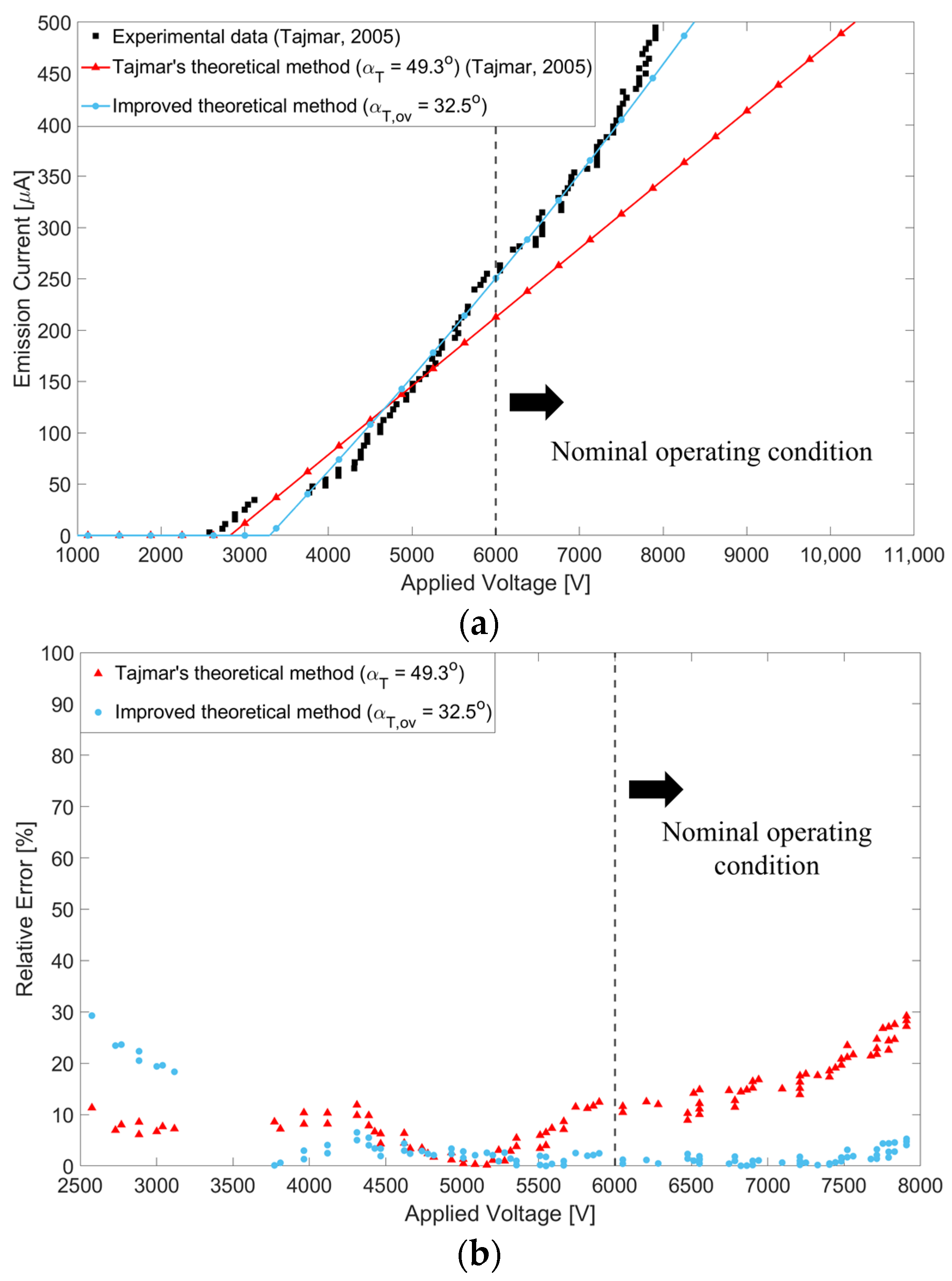
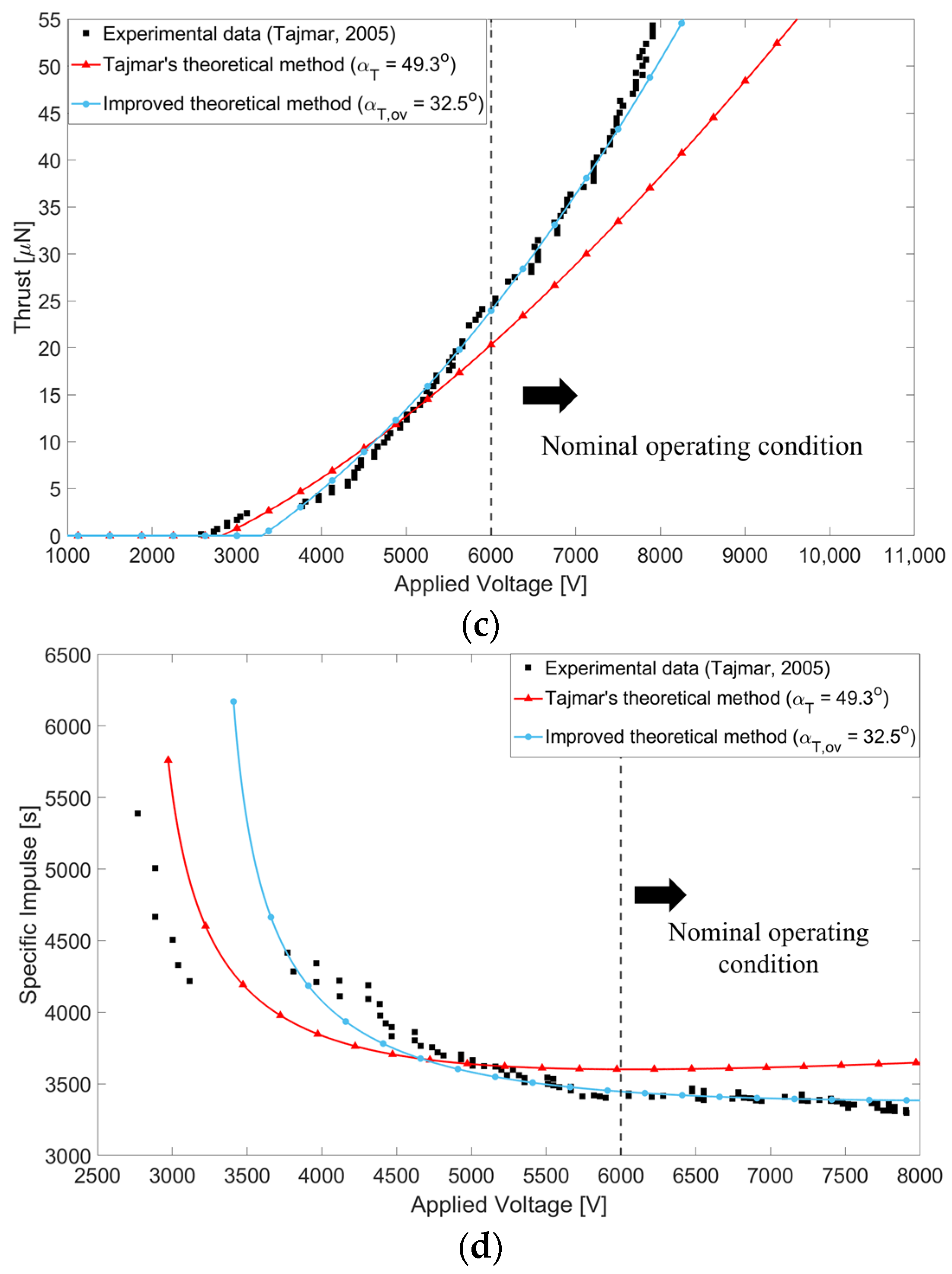
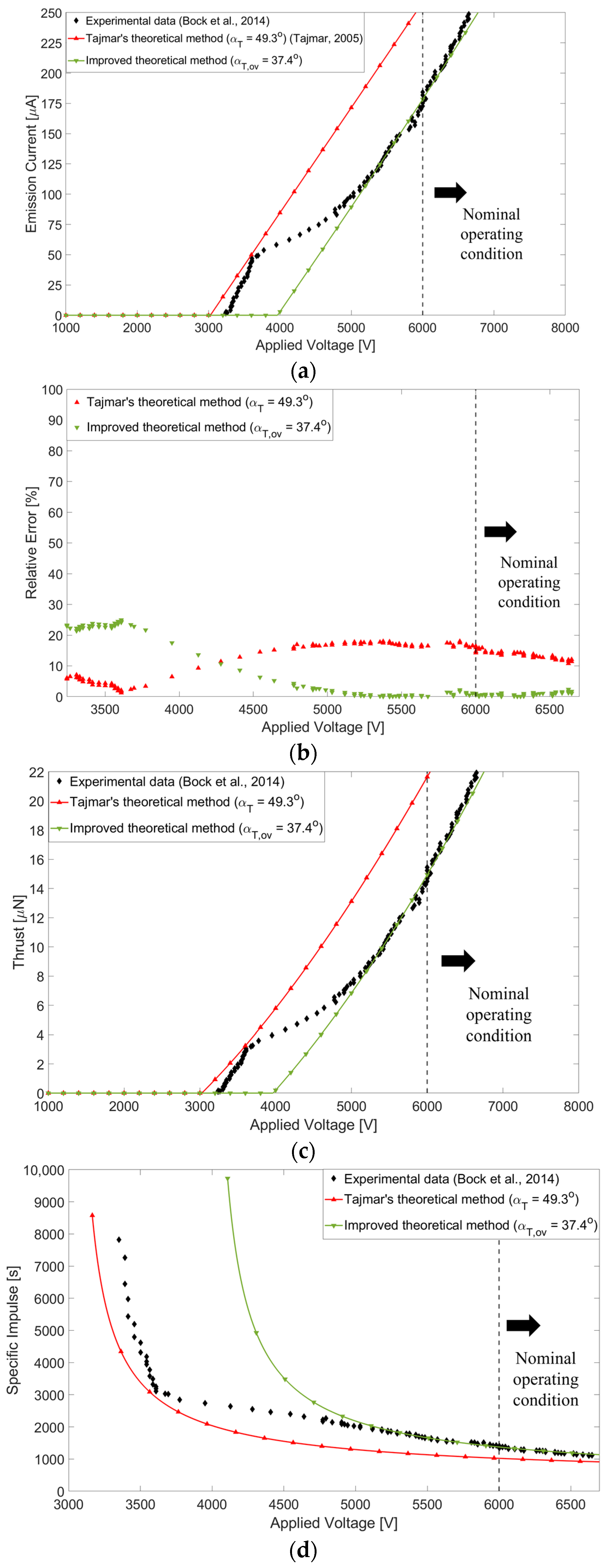
To improve the accuracy of the theoretical method, we carefully examine and derive the Iem − V and relation. As the Taylor cone starts growing at the emitter tip when the induced electric force becomes larger than the surface tension force of the liquid metal propellant, we can define the following equation for Iem based on Mair’s assumptions and equations in Ref. [18].
I e m = 3 4 V 2 q m e F e F γ
F e = 1 2 ε 0 E 2 π r b a s e 2
F γ = 2 π r b a s e γ cos α T
where Fe and Fγ indicate electric field and surface tension forces, respectively, at the Taylor cone base. By combining Equation (7) with Equations (8) and (9) and then rearranging, we can define the following Iem − V relation for a needle emitter.
I e m = 3 π 4 V 2 q m e ε 0 E 2 2   2 γ cos α T r b a s e r b a s e 2
Here, E is the electric field at the emitter tip and can be defined depending on the is the electric field at the emitter tip and can be defined depending on the shape of the needle emitter as
E = V R e m 2 ln 2 d R e m 1                  (paraboloid needle emitter)
E = V R e m 2 ln 4 d R e m 1                  (hyperboloid needle emitter)
By combining with Equations (6), (11), and (12), Equation (10) can be reformulated as Equations (13)–(15).
I e m = 3 π 2 q m e r b a s e γ cos α T 2 V V 2 V 0 x 2 1
V 0 x = ln 2 d R e m γ R e m ε 0                  (paraboloid needle emitter)
V 0 x = ln 4 d R e m γ R e m ε 0                  (hyperboloid needle emitter)
In the case where V is of a similar order to V0x, then Equation (10) can be assumed as
I e m = 3 π 2 q m e r b a s e γ cos α T 2 V V   V 0 x   1 ,    V / V 0 x 1 1
The above equations can also be valid for porous needle emitters by multiplying V0x in Equations (14) and (15) by R e m / r b a s e to consider the pores existing randomly inside the emitter [19]:
V 0 x = ln 2 d R e m γ R e m ε 0 R e m r b a s e                  (paraboloid needle emitter)
V 0 x = ln 4 d R e m γ R e m ε 0 R e m r b a s e                  (hyperboloid needle emitter)
After comparing our Equations (13) and (16) with the previous theoretical methods, we can identify some critical flaws that need to be corrected in Equations (1) and (4). First, Mair’s method in Equation (1) seems to confuse V  with V 0 x , although their difference may be small. Additionally, Equation (1) assumes that the Taylor cone base radius (rbase) is equal to the inner radius of a capillary emitter ( R ), which can cause confusion when applying Equation (1) to other emitter types. Second, Tajmar’s method in Equation (4) also seems to confuse V and V / V 0 x  with V 0  and V / V 0 , respectively. Also, the onset or starting voltage (V0) in Equation (5) is defined as a function of rbase, while we derive the extinction voltage (V0x) in Equations (14), (15), (17), and (18) as a function of R e m . Third, as the simplified forms of Equations (1) and (4) in the previous theoretical methods are assumed to be applicable only within limited current–voltage ranges of V / V 0 x 1 1 , their accuracies can deteriorate when used for high Iem − V regimes, as seen in Figure 5. Hence, we conclude that the fully defined form of Equation (13) provides more accurate and reliable predictions than the simplified equations. Fourth, Taylor theoretically calculated that the initial half angle of the Taylor cone is 49.3° at the static equilibrium between the electric field force and the liquid metal surface tension when the Taylor cone begins to rise and form at the emitter tip with V 0 [20]. Later, Driesel et al. [21] revealed through experiments that α T tends to gradually decrease as the applied voltage increases. However, we found that the previous theoretical methods fixed α T at an initial angle of 49.3° over the entire Iem − V range without considering a variation of α T depending on the applied voltage. Thus, we conclude that it is necessary to estimate a proper value of α T instead of assuming it to be 49.3°. To solve the above issues of the previous methods, we propose an improved theoretical method outlined in the flowchart in Figure 6. The correctly derived Equation (13) is chosen instead of Equations (1) and (4) to consider the nominal operating condition of the actual FEEP thruster in high voltage ranges over 3000 V. Depending on the emitter type, either Equations (14) and (15) or Equations (17) and (18) can be selected. In addition, to improve the accuracy of the present theoretical method further, a proper value of α T needed to be deduced from experimental measurements. If every individual measurement of the applied voltage were considered, then the resulting numbers of α T values would be countless, leading to difficult and complex processes to incorporate into the theoretical method. Thus, to solve this, an overall single value of α T was estimated from experimental measurements to be applicable over the given entire Iem − V range instead of using 49.3° or numerous α T values. For convenience, we define this overall single value of α T over the given Iem − V range as the overall half angle of the Taylor cone ( α T , o v ) in the present study.

3.2. Results

In this section, the present theoretical method considers two types of emitters: a needle emitter and a porous emitter. Their numerical results are depicted in Figure 7 and Figure 8, respectively, and are calculated following the procedures outlined in Figure 6 and Table 1. These results are also compared with those of the previous method and experimental data to verify the accuracy of the present method.
In the case of a needle emitter, it is observed in Figure 7a that the present theoretical method generally yields more accurate current predictions than the previous method over the entire range of given V and Iem. While the previous method shows good agreement with the experimental results [11], especially in the lower ranges of V and Iem of less than about 3200 V and 40 μA, respectively (i.e., a pure ionic emission mode), the current method fits more precisely with the experiment [11] in the upper ranges of V and Iem of about 3800–8000 V and 40–450 μA, respectively (i.e., an emission mode of ion and droplet mixture). In these ranges, the present theoretical method estimates an average relative error for V as 1.94%, while the previous method yields 12.3%, as depicted in Figure 7b. However, both methods fail to provide accurate predictions for specific regimes between 3200 and 3800 V, where sudden increases in V and Iem result in discontinuities in the IemV curve. The reason for these discontinuities is inferred to be that this regime belongs to a transition emission mode, where the pure ionic emission mode in the lower V and Iem regimes begins shifting to an emission mode of ion and droplet mixture as V and Iem increase. Additionally, to verify the performance of the FEEP thruster, thrust force (F) and specific impulse (Isp) are converted from Figure 7a data using the following equations:
F = I e m 2 V m e q · f
I s p = 1 g 2 V q m e · f · η
Here, q and me are the electric charge and the ion mass of the liquid metal propellant, respectively, and g is the gravitational acceleration. Also, f and η are the thrust factor and mass efficiency, respectively, which are assumed to be 0.8 and a function of Iem, respectively, in the present study. From Figure 7c,d, the present method also yields F and Isp more accurately in the emission mode of ion and droplet mixture within the higher voltage range of approximately 3800–8000 V. In these ranges, the present theoretical method estimates average relative errors of less than 2% for F and Isp, whereas the previous method produces several times larger errors. The nominal operating condition of the commercial FEEP thruster (i.e., approximately 6000 V [16,22]) is depicted as dashed lines in Figure 7.
At this condition, it was verified that the present method can also predict F and I s p of the actual FEEP thruster more accurately. The major reasons for the improved accuracies of the present method are inferred as follows: (1) For applications in the higher ranges of V, the present theoretical method uses a fully defined form of Equation (13) instead of a reduced form of Equation (16) to cover specific ranges of V, such as V / V 0 x 1 1 of the previous models. (2) Corrections of some flaws regarding V and V / V 0 x in the previous methods lead to an increase in the onset or starting voltage (V0) in the present method. (3) An overall half angle of the Taylor cone ( α T , o v ) estimated as 32.5° from the experimental data is used in the present method, instead of the initial half angle of the Taylor cone ( α T = 49.3 ° ) from the previous methods, to account for variations of α T depending on V in the higher ranges. As a result, a slope of the IemV curve estimated from the present method is adjusted to better fit the experimental measurements.
Next, a verification of the accuracy of the present theoretical method is also carried out for a porous emitter case. Predictions are compared with the previous method and experimental measurements [13], as seen in Figure 8. Similar to Figure 7, it is clearly demonstrated that the present method yields very accurate predictions, with relative errors of less than 2% for the emission mode of ion and droplet mixture over 4900 V, whereas the previous method shows good agreement in the pure ionic emission mode between 3200 and 3600 V. For the porous emitter, α T , o v was estimated as 37.4° from the experimental measurements [13].
When comparing Figure 7 and Figure 8, we observe that the range of the transition mode differs noticeably between the needle and porous emitters. For the needle emitter, the transition mode occurs in the relatively narrow ranges of approximately 3100–3800 V, while for the porous emitter, the transition mode spans wider ranges of approximately 3600–4900 V.
Consequently, we can conclude that the present theoretical method can provide more accurate and reliable predictions, especially in the higher V and I e m regimes, over the transition mode, including the nominal operating condition of the actual FEEP thruster.

4. Improved Electric Field Simulation Method

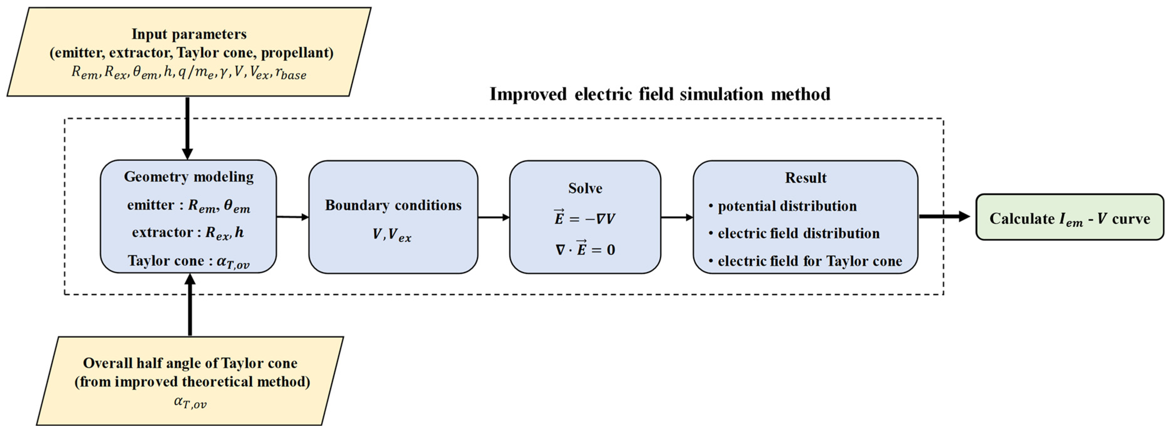
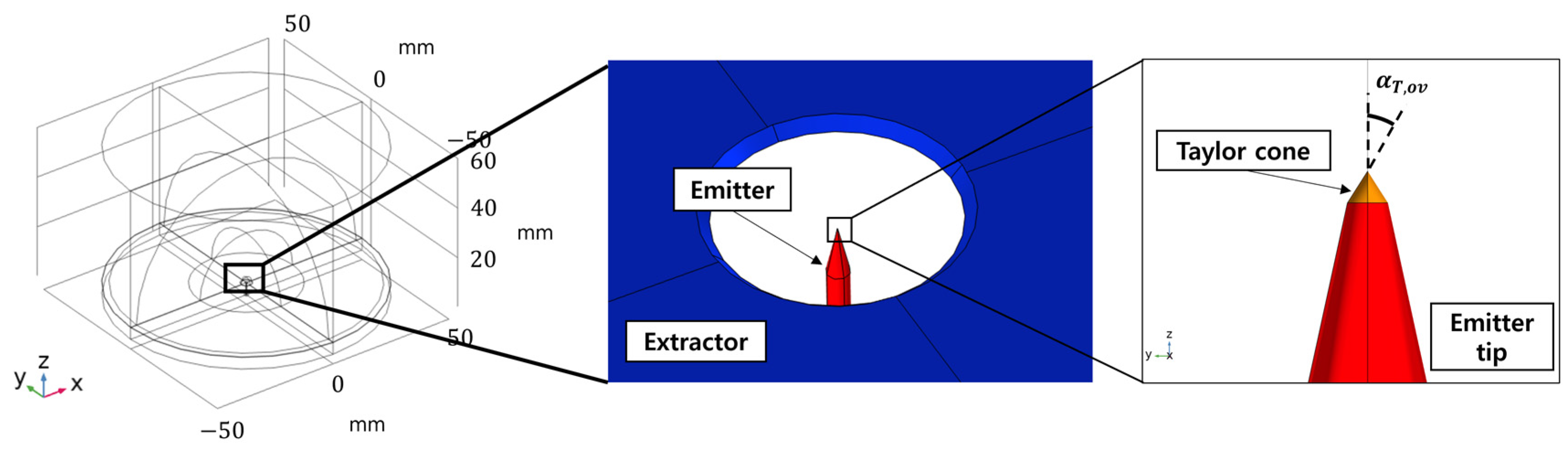
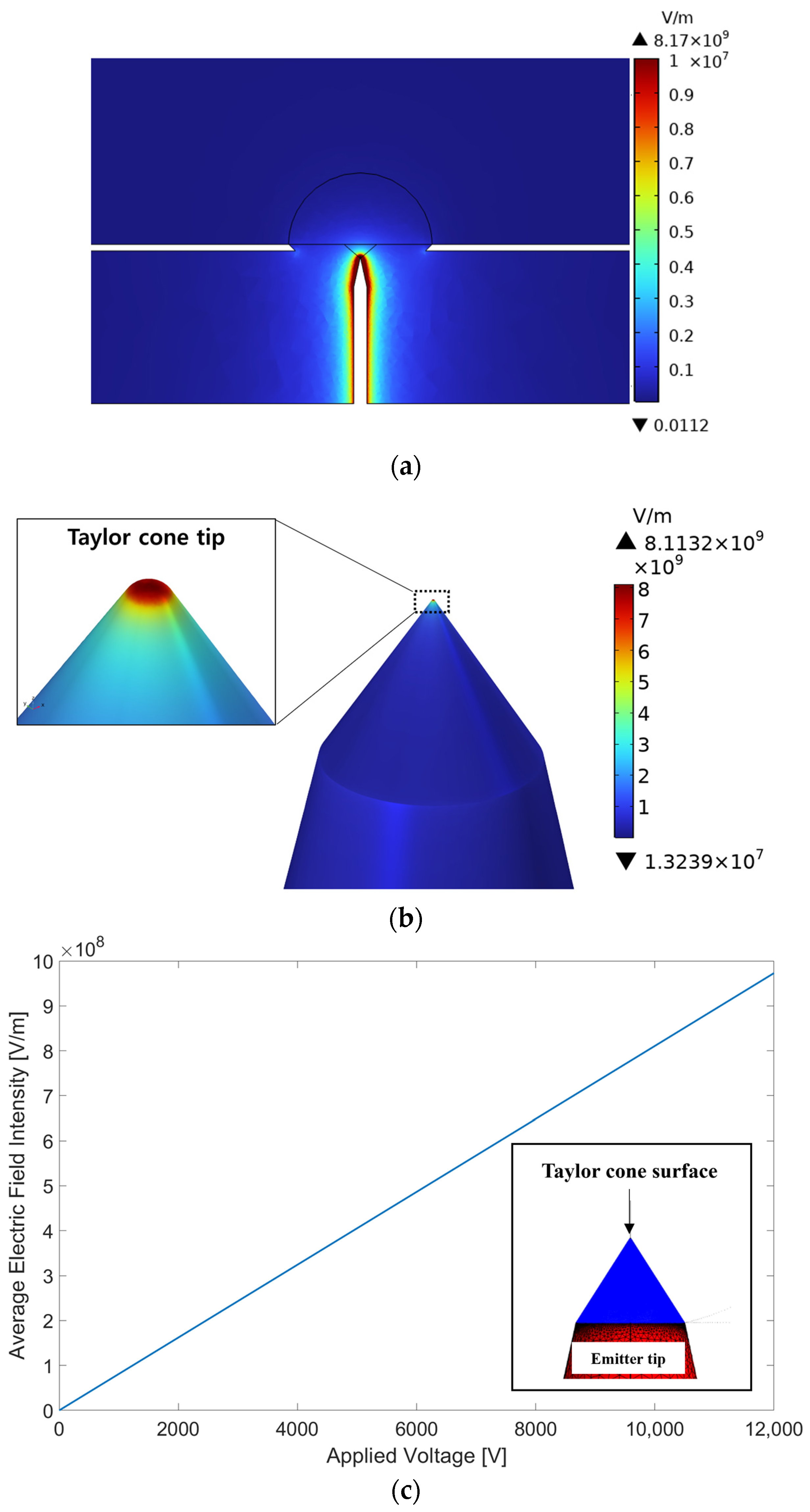
4.1. Overview and Method
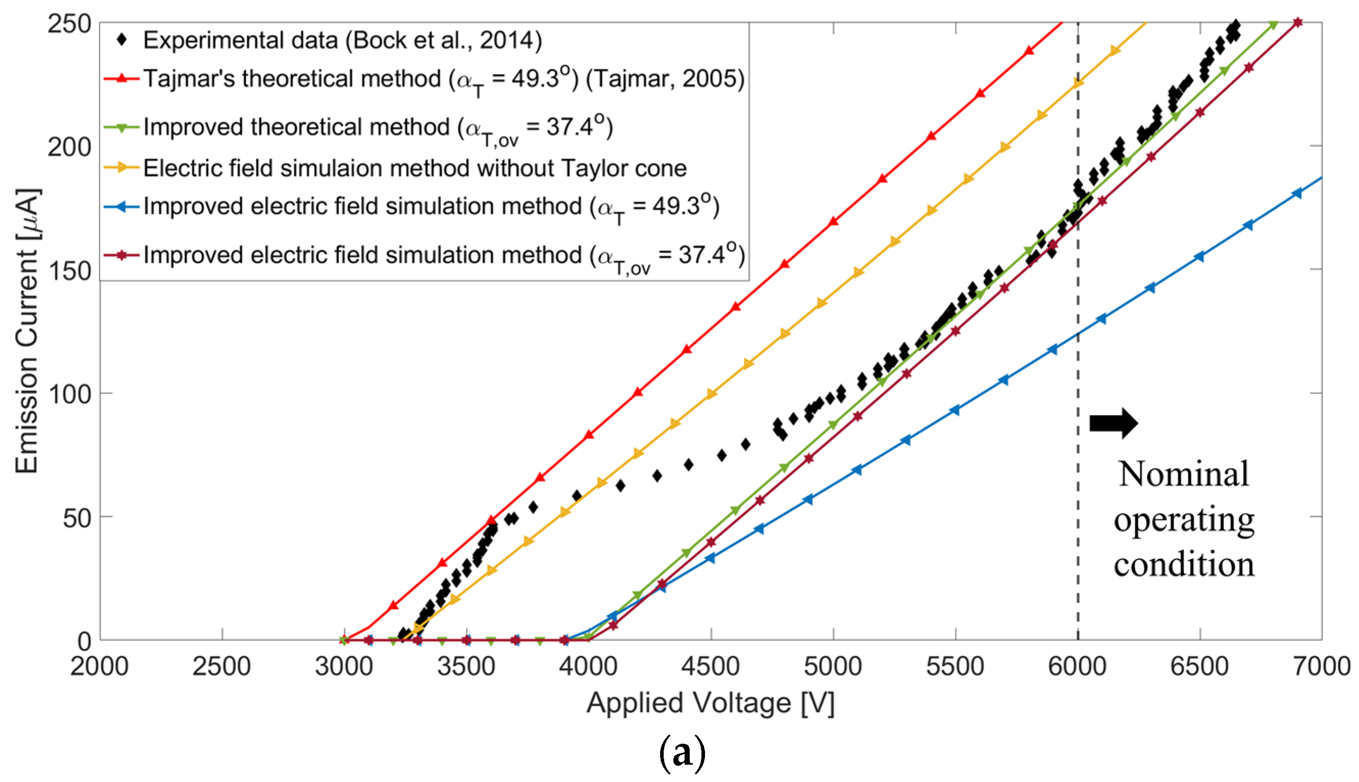
As the trajectory of extracted ions and the resulting spatial beam distribution of the FEEP thruster greatly depend on the generated electric field distribution, its accurate and detailed simulation in a three-dimensional domain is very important when designing a new FEEP thruster with its non-symmetric complex configuration to match specific thrust or spatial beam requirements. In general, the electric field distribution of the FEEP thruster tends to vary depending not only on the applied voltage between the emitter and extractor but also on the geometric configurations of the emitter and Taylor cone. However, we found that previous electric field simulation studies of the FEEP thrusters usually considered the simple configurations of the emitter and extractor in an axisymmetric domain, rarely incorporating the Taylor cone into their models. This omission is primarily due to the Taylor cone’s tiny size and the difficulties in achieving numerical convergence in the simulation of the Taylor cone’s growth, caused by the inherent electrical characteristics of the liquid metal propellants, such as their high relative permittivity (≥106 F/m), etc. To solve the above issues of previous studies, we propose an improved electric field simulation method outlined in the flowchart in Figure 9. The simulation was performed using the COMSOL Multiphysics software to predict the spatial electric field distributions of the FEEP thruster in a three-dimensional domain by solving the following electrostatic equation of Gauss’s law without space charge density.
· E = 0
The present electric field simulation model consisted of an emitter, an extractor, and a vacuum region using tetrahedral meshes, as illustrated in Figure 10. The Taylor cone configuration was implemented at the emitter tip as a simple cone with the overall half angle of Taylor cone ( α T , o v ) estimated from the present theoretical method instead of using 49.3° or varying values of α T  with V. The voltage was applied to the emitter surface including the Taylor cone, while an extractor voltage (Vex) was allocated at the extractor surface. After the simulation was completed, the average value of the electric field (Eagv) was estimated over the entire surface of the Taylor cone. Then, the IemV relation was calculated from Equation (10) using Eagv instead of E.

4.2. Results

In this section, the present electric field simulation method considers again both types of emitters, a needle and a porous emitter. Representative simulation results are depicted in Figure 11, Figure 12 and Figure 13 based on the procedures outlined in Figure 9 and the input parameters listed in Table 2. These results are also compared with the results of theoretical models and experimental data to verify the accuracy of the present electric field simulation method.
First, the three-dimensional electric field distributions for the needle emitter simulated with V = 6 kV and Vex = 0 kV are depicted in Figure 11 as a representative case. Here, the Taylor cone was implemented into the electric field simulation model with α T , o v = 32.5 ° for the needle emitter and α T , o v = 37.4 °  for the porous emitter based on the estimation results obtained from the present theoretical method shown in Figure 7 and Figure 8. The present simulation predicted the electric field distribution for both types of emitters would be less than approximately 107 V/m between the emitters and extractors, as seen in Figure 11a. However, maximum values exceeding 5 × 10⁹ V/m were observed at the tips of the Taylor cone because of their sharpness, as shown in Figure 11b for both types of emitters. From this, it was revealed that implementing the Taylor cone into the electric field simulation model is important because a strong concentration of the electric field greater than can be predicted at the Taylor cone tip, which is the threshold for the field evaporation mechanism that extracts and accelerates ions from the Taylor cone tip. Variations in the average electric fields on the entire Taylor cone surface are plotted in Figure 11c for V = 0–12 kV and Vex = 0 kV, showing a linear relation with increasing V.
To verify the accuracy of the present electric field simulation method, IemV relations for both types of emitters were calculated from Equation (10) using E a v g plotted in Figure 11c and then compared with the results from the theoretical methods and experimental data, as shown in Figure 12 and Figure 13. It was observed that the present electric field simulation method including the Taylor cone with given α T , o v predicted very accurate IemV profiles similar to those of the present improved theoretical methods for both emitter types, whereas other electric field simulation methods showed somewhat large deviations. The average relative errors of IemV relations for electric field simulations with experimental data are also summarized in Table 3 for higher V and Iem regimes over the transition mode of the ion and droplet mixture’s emission. From Figure 12 and Figure 13 and Table 3, we conclude that both the present theoretical and electric field simulation methods including the Taylor cone with given α T , o v can predict experimental results more accurately, especially for higher V and Iem regimes, which correspond to the actual operating conditions of the FEEP thruster, while the previous method shows large deviations relative to the experiments.

5. Conclusions

In this study, we first aimed to investigate and propose an improved theoretical method to predict the performance of the FEEP thruster more accurately with its complex configuration. To achieve this, we identified critical flaws in the previous theoretical methods and derived corrected equations. Additionally, we defined and implemented the overall half angle of the Taylor cone to account for variations in the Taylor cone’s half angle depending on the applied voltage rather than using the conventional value of 49.3°. Next, we also aimed to establish an improved method of the electric field simulation in a three-dimensional domain to accurately predict a trajectory of extracted ions and a resulting spatial beam distribution of the FEEP thruster by incorporating the predicted outcomes of the proposed theoretical method. For this, we incorporated the configuration of the Taylor cone with the estimated overall half angle into the present electric field simulation model, which was conventionally ignored in previous axisymmetric simulations. Through comparison with the experimental measurements, we found that the present improved methods for theoretical and electric field simulations including the Taylor cone with given α T , o v can yield more accurate predictions rather than the previous methods, especially for higher V and Iem regimes, which correspond to the actual operating conditions of the FEEP thruster.
Consequently, we anticipate that the proposed methods can enhance the reliability and efficiency of the design process by accurately predicting performance when developing the new FEEP thruster with its non-symmetry complex configuration to match specific thrust or spatial beam requirements. As the next step, we are conducting further investigations to accurately predict and evaluate the spatial beam distribution of newly designed FEEP thrusters in a three-dimensional domain.

Author Contributions

Conceptualization, K.H.L.; methodology, J.S. and K.H.L.; software, J.S. and K.H.L.; validation, J.S. and K.H.L.; formal analysis, J.S. and K.H.L.; investigation, J.S. and K.H.L.; resources, K.H.L.; data curation, J.S. and K.H.L.; writing—original draft preparation, J.S. and K.H.L.; writing—review and editing, K.H.L.; visualization, J.S. and K.H.L.; supervision, K.H.L.; project administration, K.H.L., J.K. and H.S.K.; funding acquisition, K.H.L., J.K. and H.S.K. All authors have read and agreed to the published version of the manuscript.

Funding

This work was supported by the Space Challenge Project (NRF-2021M1A3B8078958) and Future Space Navigation & Satellite Research Center Program (NRF-2022M1A3C2074404) through the National Research Foundation funded by the Ministry of Science and ICT of Republic of Korea.

Data Availability Statement

The data presented in this study are available on request from the corresponding author.

Conflicts of Interest

The authors declare no conflicts of interest.

Nomenclature

amuatomic mass unit, 1.66054 × 10⁻²⁷ kg
dstraight distance between an emitter tip and an extractor, m
Eelectric field, V/m
Eavgaverage value of electric field, V/m
Fthrust, N
fthrust factor
Feelectric field force at the Taylor cone base, N
Fγsurface tension force at the Taylor cone base, N
hvertical distance between an emitter tip and an extractor, m
Iememission current, A
Ispspecific impulse, s
knumerical constant
meion mass of liquid metal propellant, kg
ggravitational acceleration, 9.81 m/s2
qelectric charge of ion, 1.60218 × 10⁻¹⁹ C
Rinner radius of capillary emitter, m
Remradius of emitter tip, m
Rexradius of extractor, m
rbaseradius of Taylor cone base, m
Vapplied voltage, V
V0onset or starting voltage, V
V0xextinction voltage, V
Vexextractor voltage, V
Greek symbols
αTTaylor cone half angle
αT,ovoverall Taylor cone half angle
ε0vacuum permittivity, 8.85419 × 10⁻¹² F/m
γsurface tension, N/m2
θ e m emitter tip half angle, °

References

  1. Alnaqbi, S.; Darfilal, D.; Swei, S.S.M. Propulsion technologies for CubeSats: Review. Aerospace 2024, 11, 502. [Google Scholar] [CrossRef]
  2. Andrenucci, M.; Marcuccio, S.; Spagli, L.; Genovese, A.; Repola, F. Experimental study of FEEP emitter starting characteristics. In Proceedings of the 22nd International Electric Propulsion Conference, Viareggio, Italy, 14–17 October 1991; pp. 1–7. [Google Scholar]
  3. Marcuccio, S.; Giannelli, S.; Andrenucci, M. Attitude and orbit control of small satellites and constellations with feep thrusters. In Proceedings of the 25th International Electric Propulsion Conference, Cleveland, OH, USA, 24–28 August 1997; pp. 1152–1159. [Google Scholar]
  4. Marcuccio, S.; Genovese, A.; Andrenucci, M. Experimental performance of field emission microthrusters. J. Propuls. Power 1998, 14, 774–781. [Google Scholar] [CrossRef]
  5. Nicolini, D.; Chesta, E.; Gonzalez del Amo, J.; Saccoccia, G.; Hughes, E.B.; Oldfield, S. FEEP-5 thrust validation in the 10–100 µN range with a simple nulled-pendulum thrust stand: Integration procedures. In Proceedings of the 27th International Electric Propulsion Conference, Pasadena, CA, USA, 15–19 October 2001; pp. 1–9. [Google Scholar]
  6. Paita, L.; Ceccanti, F.; Spurio, M.; Cesari, U.; Priami, L.; Nania, F.; Rossodivita, A.; Andrenucci, M. Alta’s FT-150 FEEP microthruster: Development and qualification status. In Proceedings of the 31st International Electric Propulsion Conference, Ann Arbor, MI, USA, 20–24 September 2009; pp. 1–9. [Google Scholar]
  7. Tajmar, M.; Scharlemann, C.; Genovese, A.; Buldrini, N.; Steiger, W.; Vasiljevich, I. Liquid-metal-ion source development for space propulsion at ARC. Ultramicroscopy 2009, 109, 442–446. [Google Scholar] [CrossRef] [PubMed]
  8. Vasiljevich, I.; Tajmar, M.; Grienauer, W.; Plesescu, F.; Buldrini, N.; Gonzalez del Amo, J.; Carnicero Domunguez, B.; Betto, M. Development of an indium mN FEEP thruster. In Proceedings of the 44th AIAA/ASME/SAE/ASEE Joint Propulsion Conference & Exhibit, Hartford, CT, USA, 21–23 July 2008; pp. 1–9. [Google Scholar]
  9. Krejci, D.; Reissner, A.; Schönherr, T.; Koch, Q.; Hugonnaud, V.; Grimaud, L.; Vogel, T.; Seifert, B. Informing FEEP thruster design utilizing the flight heritage from 167 thrusters in LEO and GEO. In Proceedings of the AIAA SCITECH 2024 Forum, Orlando, FL, USA, 8–12 January 2024; pp. 1–8. [Google Scholar]
  10. Tajmar, M.; Genovese, A.; Steiger, W. Indium field emission electric propulsion microthruster experimental characterization. J. Propuls. Power 2004, 20, 211–218. [Google Scholar] [CrossRef]
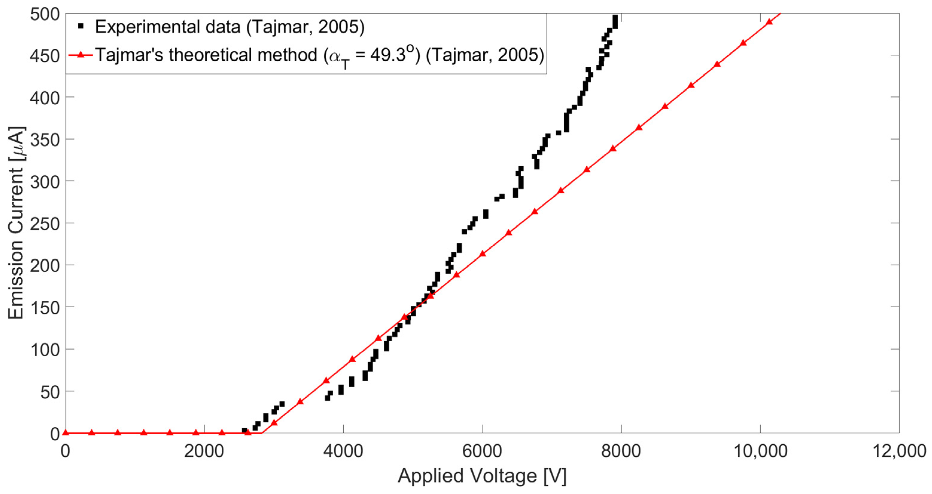
  11. Tajmar, M. Influence of Taylor cone size on droplet generation in an indium liquid metal ion source. Appl. Phys. A 2005, 81, 1447–1450. [Google Scholar] [CrossRef]
  12. Tajmar, M. Development of a lifetime prediction model for indium FEEP thrusters. In Proceedings of the 41st AIAA/ASME/SAE/ASEE Joint Propulsion Conference & Exhibit, Tucson, AZ, USA, 10–13 July 2005; pp. 1–17. [Google Scholar]
  13. Bock, D.; Bethge, M.; Tajmar, M. Highly miniaturized FEEP thrusters for CubeSat applications. In Proceedings of the 4th Spacecraft Propulsion Conferences, Cologne, Germany, 19–22 May 2014; pp. 1–9. [Google Scholar]
  14. Wu, X.; Oleschuk, R.D.; Cann, N.M. Characterization of microstructured fibre emitters: In pursuit of improved nano electrospray ionization performance. Analyst 2012, 137, 4150–4161. [Google Scholar] [CrossRef] [PubMed]
  15. Khalil, A.; Lalia, B.S.; Hashaikeh, R.; Khraisheh, M. Electrospun metallic nanowires: Synthesis, characterization, and applications. J. Appl. Phys. 2013, 114, 171301. [Google Scholar] [CrossRef]
  16. Jelem, D.; Seifert, B.; Sypniewski, R.; Buldrini, N.; Reissner, A. Performance mapping and qualification of the IFM Nano thruster FM for in orbit demonstration. In Proceedings of the 53rd AIAA/SAE/ASEE Joint Propulsion Conference, Atlanta, GA, USA, 10–12 July 2017; pp. 1–12. [Google Scholar]
  17. Peter, B.S.; Dressler, R.A.; Chiu, Y.-h.; Fedkiw, T. Electrospray Propulsion Engineering Toolkit (ESPET). Aerospace 2020, 7, 91. [Google Scholar] [CrossRef]
  18. Mair, G.L.R. Theoretical determination of current-voltage curves for liquid metal ion sources. J. Phys. D Appl. Phys. 1984, 17, 2323–2330. [Google Scholar] [CrossRef]
  19. Dressler, R.A.; Peter, B.S. Electrospray Propulsion Engineering Toolkit, ESPET 1.0; Spectral Sciences, Inc.: Burlington, MA, USA, 2018. [Google Scholar]
  20. Taylor, G.I. Disintegration of water drop in an electric field. Proc. R. Soc. Lond. A Math Phys. Sci. 1964, 280, 383–390. [Google Scholar]
  21. Driesel, W.; Dietzsch, C.; Möser, M. In situ HV TEM observation of the tip shape of lead liquid metal ion sources. J. Phys. D Appl. Phys. 1996, 29, 2492–2500. [Google Scholar] [CrossRef]
  22. ENPULSION GmbH. ENPULSION NANO Thruster Product Data Sheet; ENPULSION GmbH.: Wien-Flughafen, Austria, 2024. [Google Scholar]
Figure 1. A schematic of the FEEP thruster.
Aerospace 11 00716 g001
Figure 2. Force distribution on Taylor cone [14] and formation of Taylor cone [15].
Aerospace 11 00716 g002
Figure 3. Diagrams of three emitter types of FEEP thrusters [16].
Aerospace 11 00716 g003
Figure 4. Schematics of Taylor cone configurations for different emitter tips. (a) A capillary emitter; (b) a needle emitter.
Aerospace 11 00716 g004
Figure 5. Comparison of previous theoretical method with experiment [11].
Aerospace 11 00716 g005
Figure 6. A flowchart of the present improved theoretical method.
Aerospace 11 00716 g006
Figure 7. Performance comparisons of the improved theoretical method for a needle emitter. (a) Predictions of IemV relation [11]; (b) relative errors for predicted IemV relations; (c) predictions of FV relation; (d) predictions of IspV relation.
Aerospace 11 00716 g007aAerospace 11 00716 g007b
Figure 8. Performance comparisons of the improved theoretical method for a porous emitter. (a) Predictions of IemV relation [11,13]; (b) relative errors for predicted IemV relations; (c) predictions of FV relation; (d) predictions of IspV relation.
Aerospace 11 00716 g008
Figure 9. A flowchart of improved electric field simulation method.
Aerospace 11 00716 g009
Figure 10. A 3-D configuration of the improved electric field simulation model.
Aerospace 11 00716 g010
Figure 11. Electric field intensity results for a needle emitter using the present method. (a) Electric field intensity in the simulation region with an emitter and an extractor (V = 7 kV); (b) electric field intensity on Taylor cone and emitter surfaces (V = 7 kV); (c) average electric field intensity on Taylor cone surface (V = 0–12 kV).
Aerospace 11 00716 g011
Figure 12. Performance comparisons of the improved electric field simulation method for a needle emitter. (a) Predictions of IemV relation [11]; (b) predictions of FV relation; (c) predictions of IspV relation.
Aerospace 11 00716 g012aAerospace 11 00716 g012b
Figure 13. Performance comparisons of the improved electric field simulation method for a porous emitter. (a) Predictions of IemV relation [11,13]; (b) predictions of FV relation; (c) predictions of IspV relation.
Aerospace 11 00716 g013aAerospace 11 00716 g013b
Table 1. Parameters of emitters and liquid metal propellants used in the experiments.
Emitter TypeRem [μm]d [mm]Liquid Metal Propellant
Typeme [kg]γ [N/m]
Needle emitter [11]3.45042Indium1.9066 × 10−250.5607
Porous emitter [13]31.9Gallium1.1578 × 10−250.7226
Table 2. Geometry parameters and boundary conditions for electric field simulation.
Emitter TypeGeometryBoundary
Condition
Rem [μm]Rex [mm]αT,ov [°]θem [°]h [mm]V [kV]Vex [kV]
Needle emitter [11]3.4504232.512.50.20–120
Porous emitter [13]31.937.4160.53–7
Table 3. Average relative errors of IemV relations for electric field simulations.
Emitter TypeAverage Relative Errors of IemV Relations with Experiments [%]
Tajmar’s Theoretical MethodImproved Theoretical
Method
Electric Field
Simulation Without
Taylor Cone
Electric Field
Simulation with
Taylor Cone
(αT = 49.3°)
Improved
Electric Field
Simulation
(αT,ov = 32.5°/37.4°)
Needle emitter12.2731.9405.32521.5392.320
Porous emitter15.2670.7529.06411.2122.068
Disclaimer/Publisher’s Note: The statements, opinions and data contained in all publications are solely those of the individual author(s) and contributor(s) and not of MDPI and/or the editor(s). MDPI and/or the editor(s) disclaim responsibility for any injury to people or property resulting from any ideas, methods, instructions or products referred to in the content.

