
The Design and Analysis of Reinforcement Schemes for Pultruded Rod Stitched Efficient Unitized Structure Open-Panel Structures


Abstract
:1. Introduction
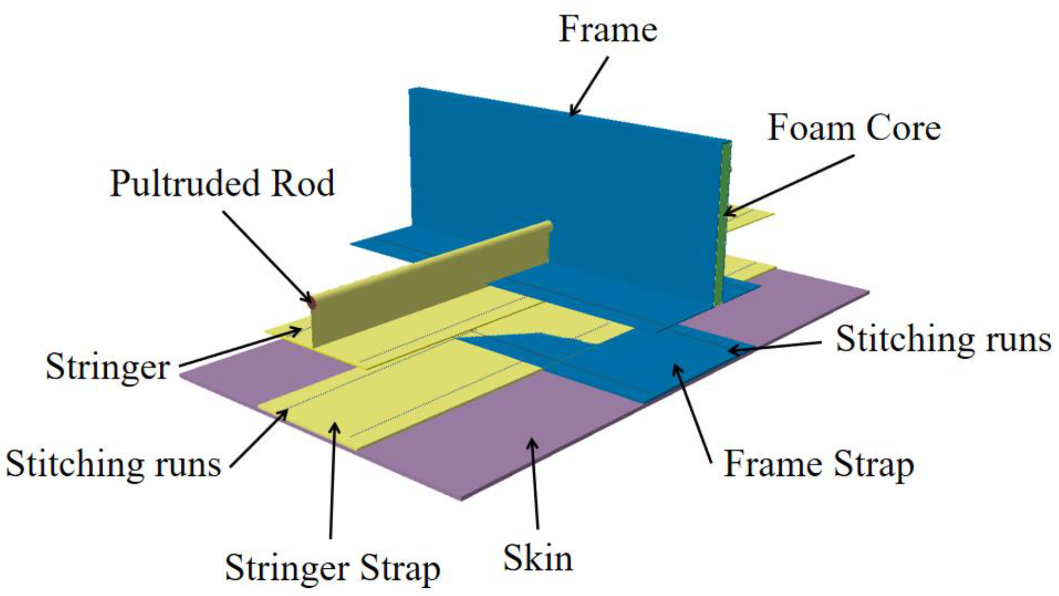
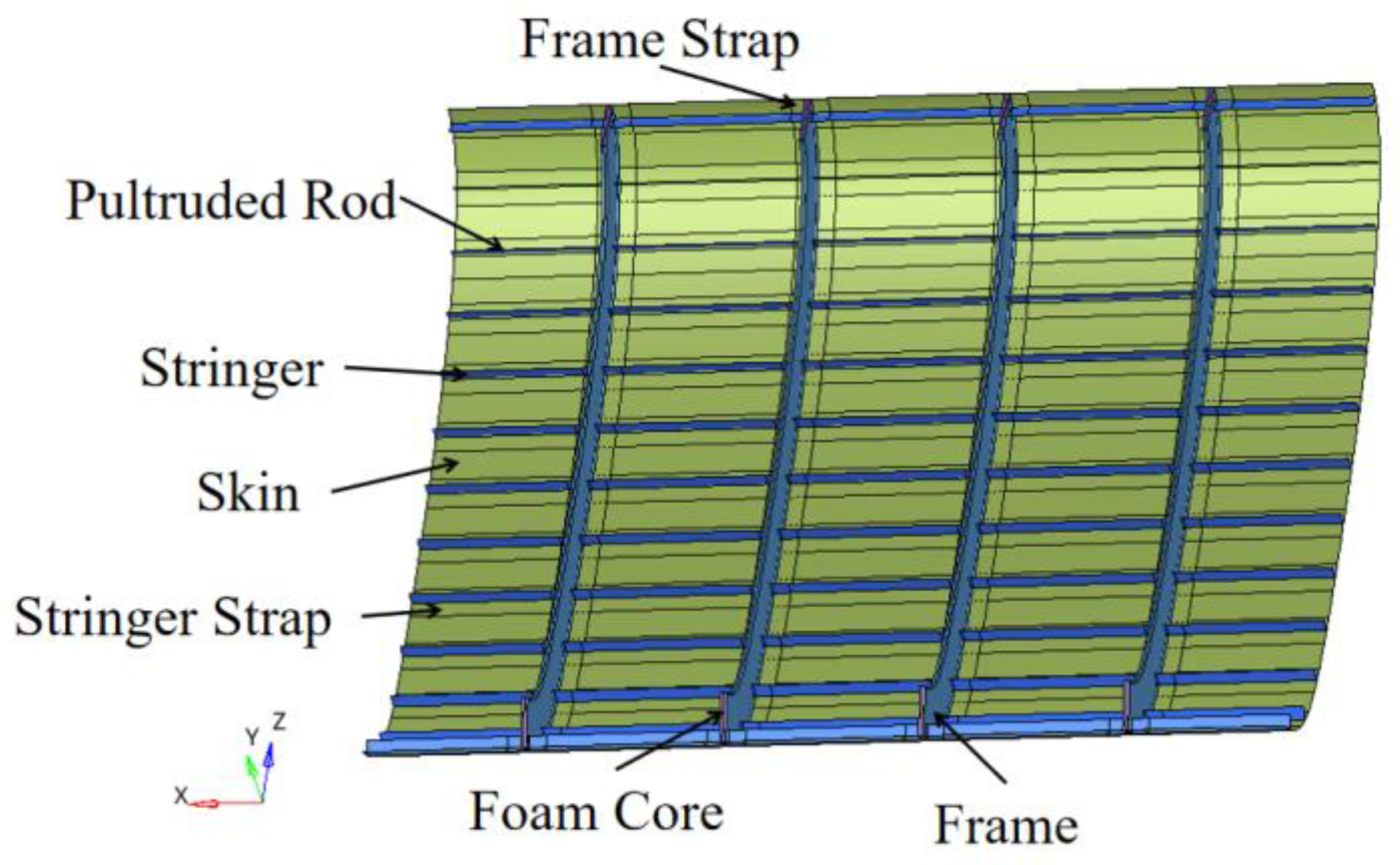
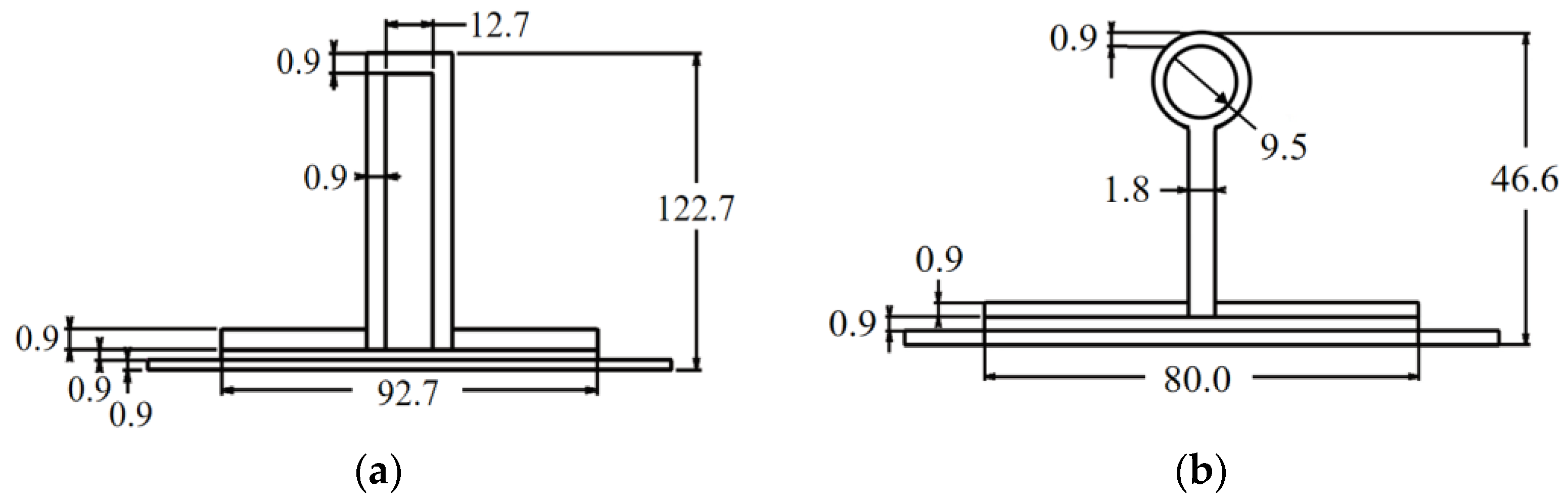
1.1. Introduction to PRSEUS Structural Elements
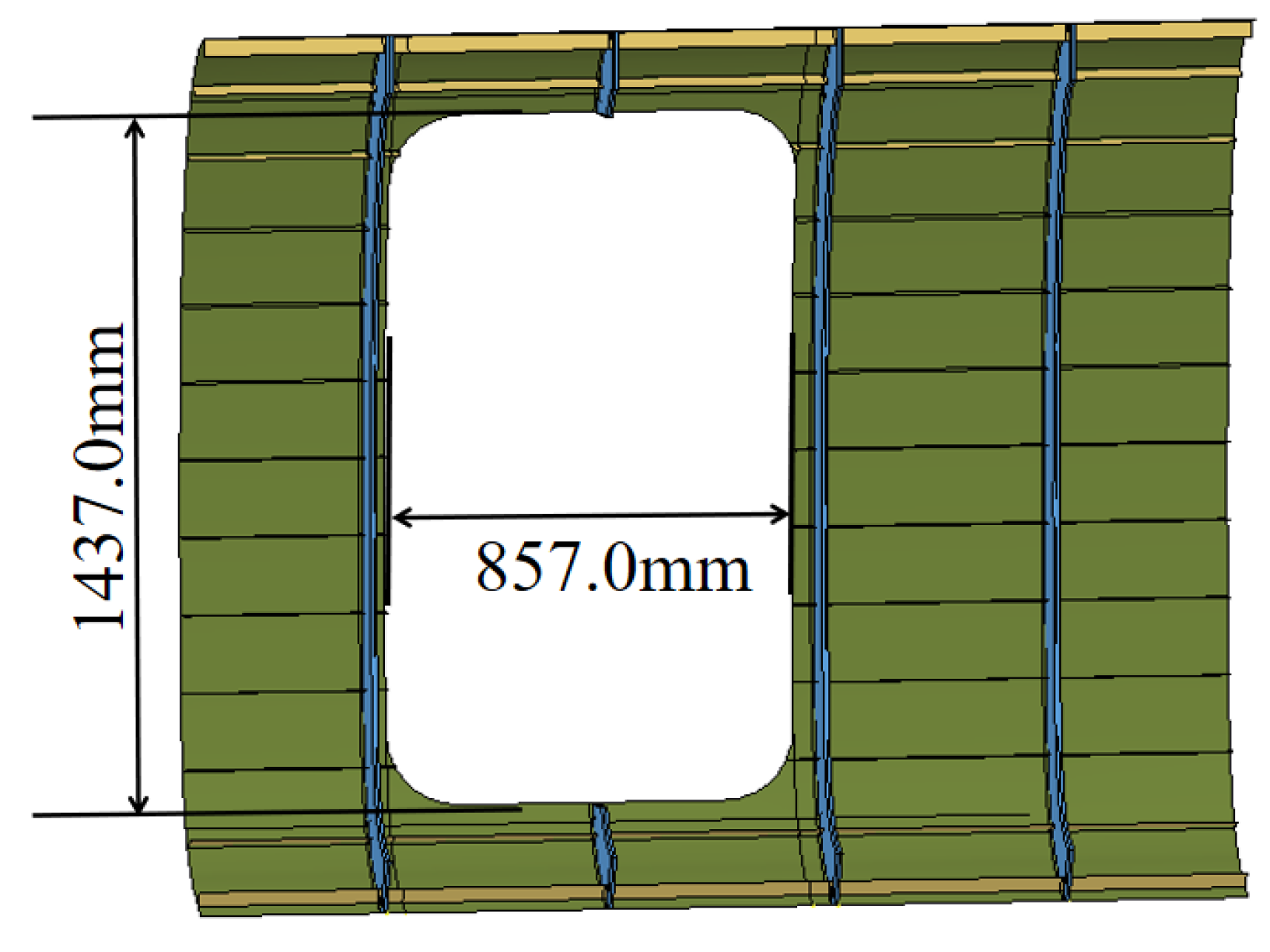
1.2. Small-Opening Panel Design
1.3. Mid-Sized-Opening Panel Design
2. Finite Element Model of Panel Pane
2.1. Model Material
2.2. Mesh Convergence Analysis
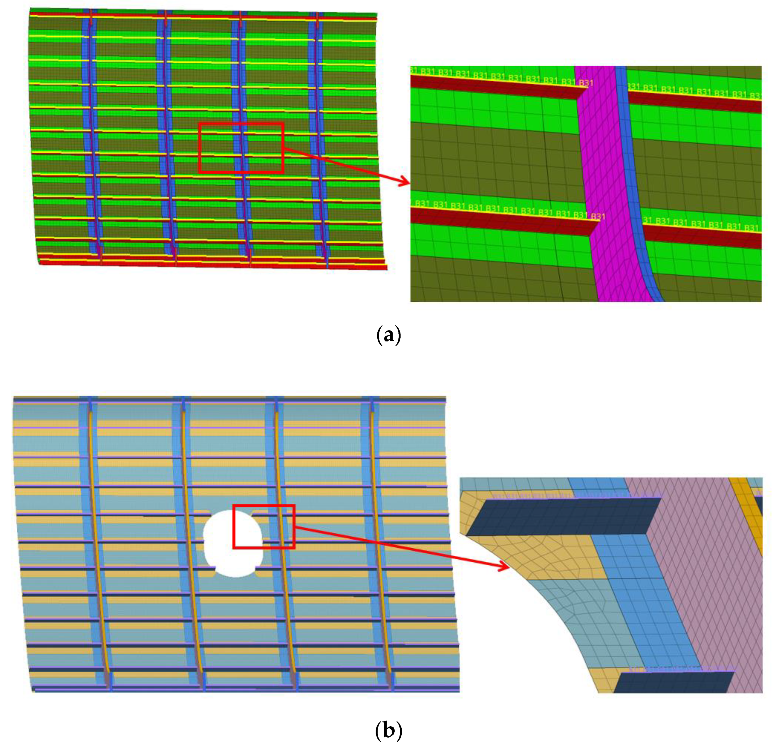
2.3. Structural Meshing
2.4. Boundary Conditions
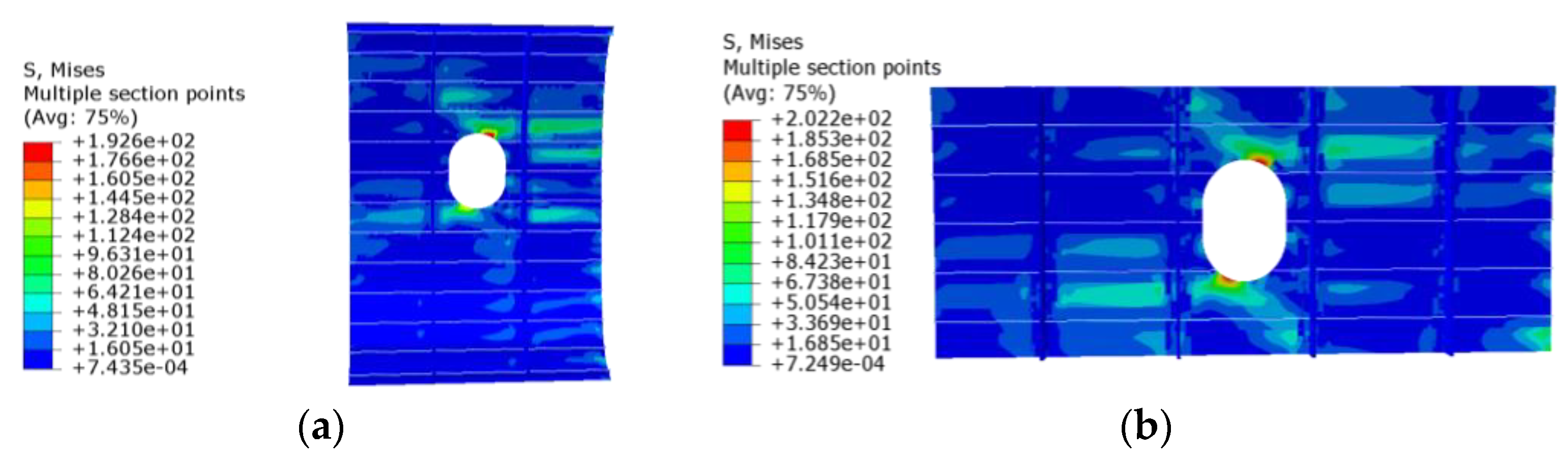
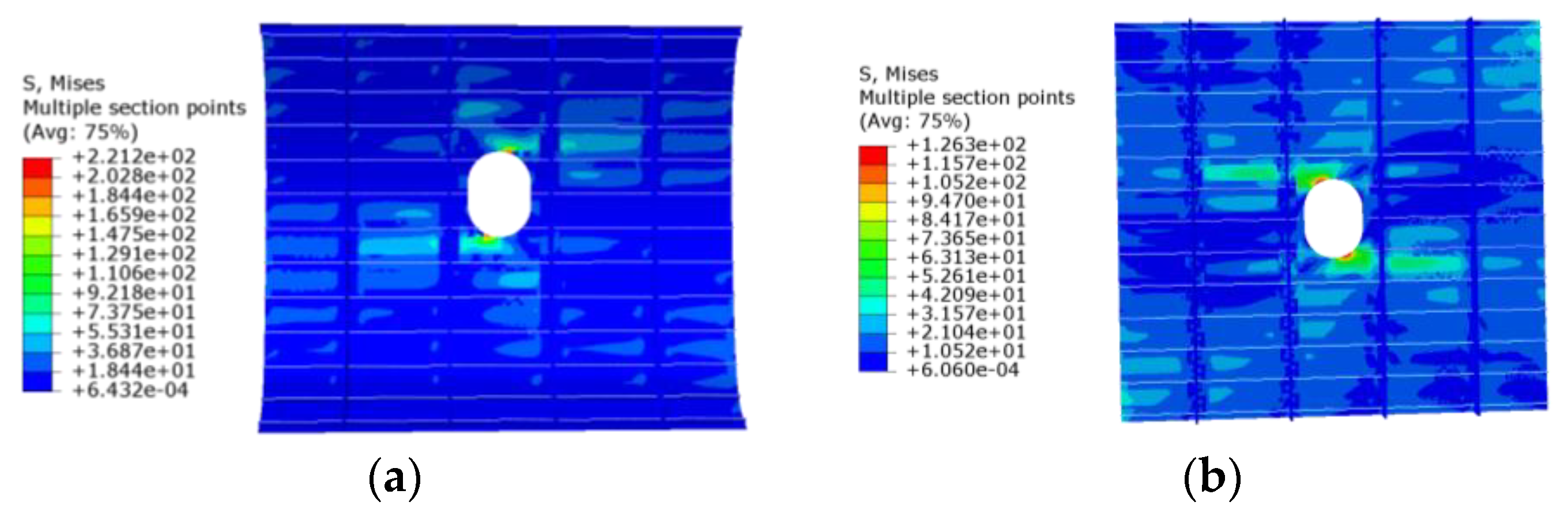
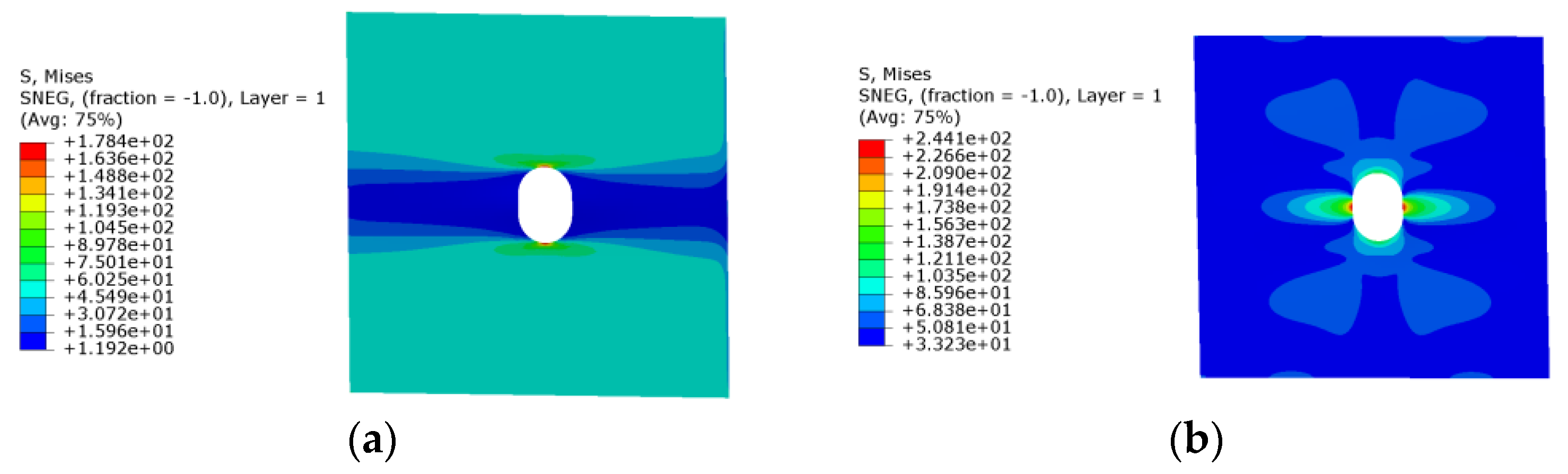
2.5. Opening Panel Stress Analysis
3. Reinforcement Design and Analysis of Typical PRSEUS Panel Structures with a Small Opening
3.1. Design of Reinforcement Schemes of a Typical PRSEUS Panel Structure with a Small Opening
3.2. Tensile Load Analysis of PRSEUS Panels and Reinforced Structures with a Small Opening
3.3. Compressive Load Analysis of PRSEUS Panels and Reinforced Structures with a Small Opening
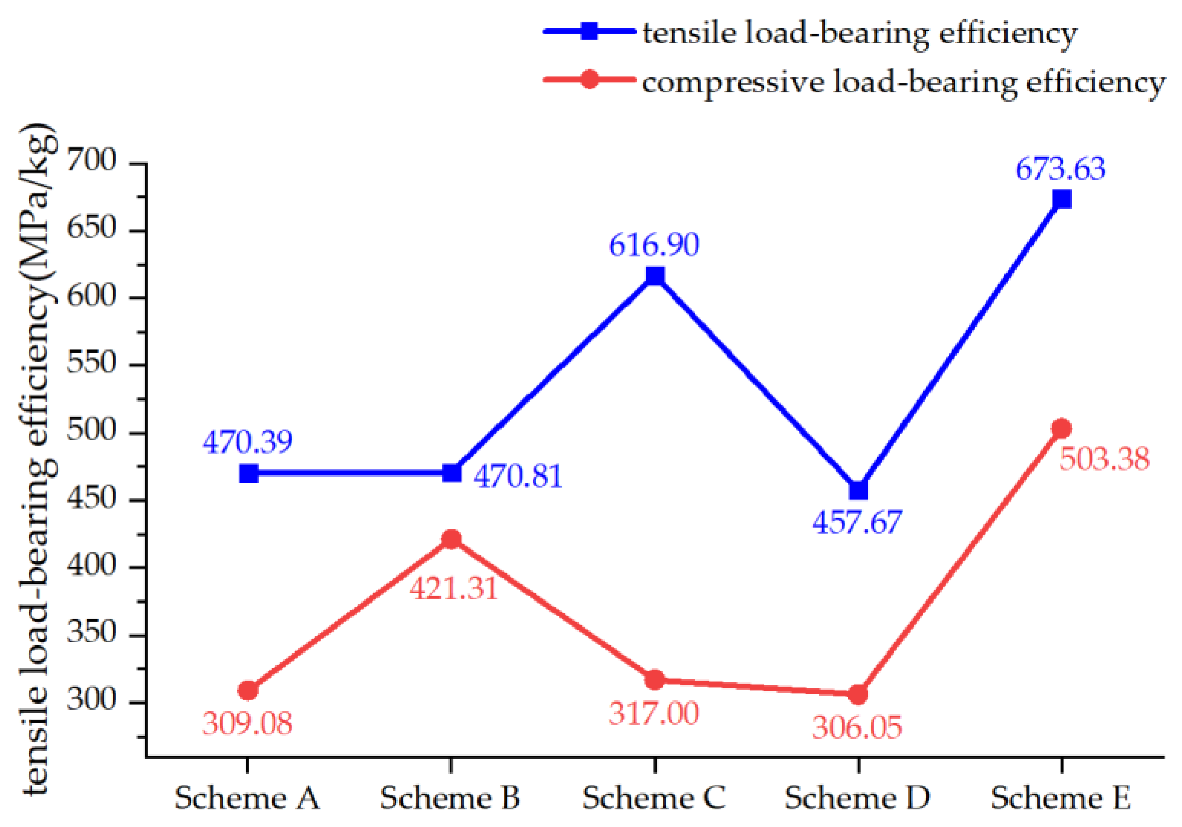
3.4. Load-Bearing Efficiency Analysis of Reinforced PRSEUS Panels with a Small Opening
4. Reinforcement Design and Analysis of Typical PRSEUS Panel Structure with a Mid-Sized Opening
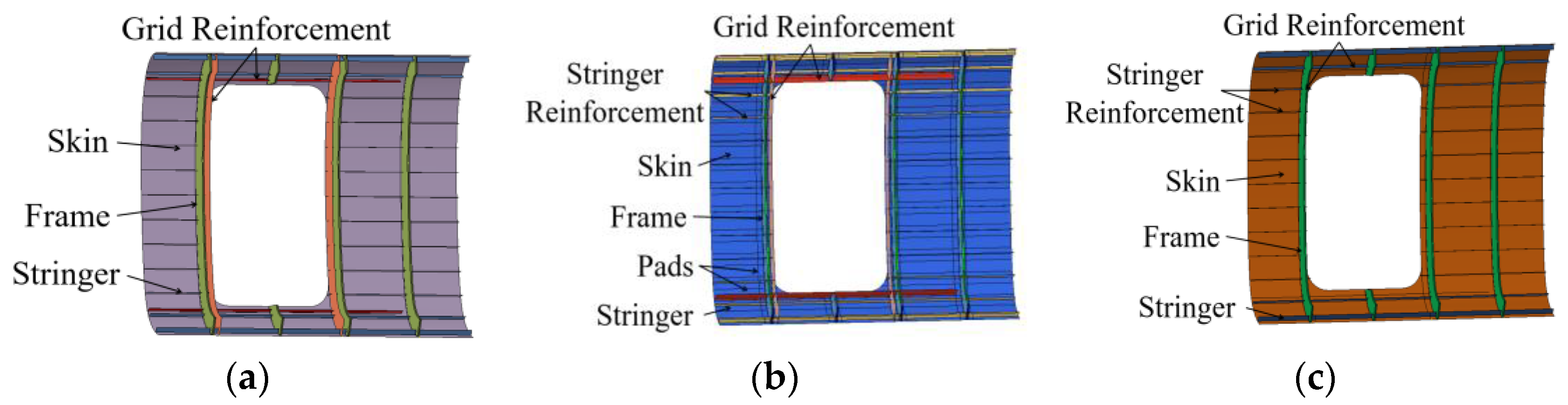
4.1. Design of Reinforcement Scheme of Typical PRSEUS Panel Structures with a Mid-Sized Opening
4.2. Tensile Load Analysis of Typical PRSEUS Panels and Reinforced Structures with a Mid-Sized Opening
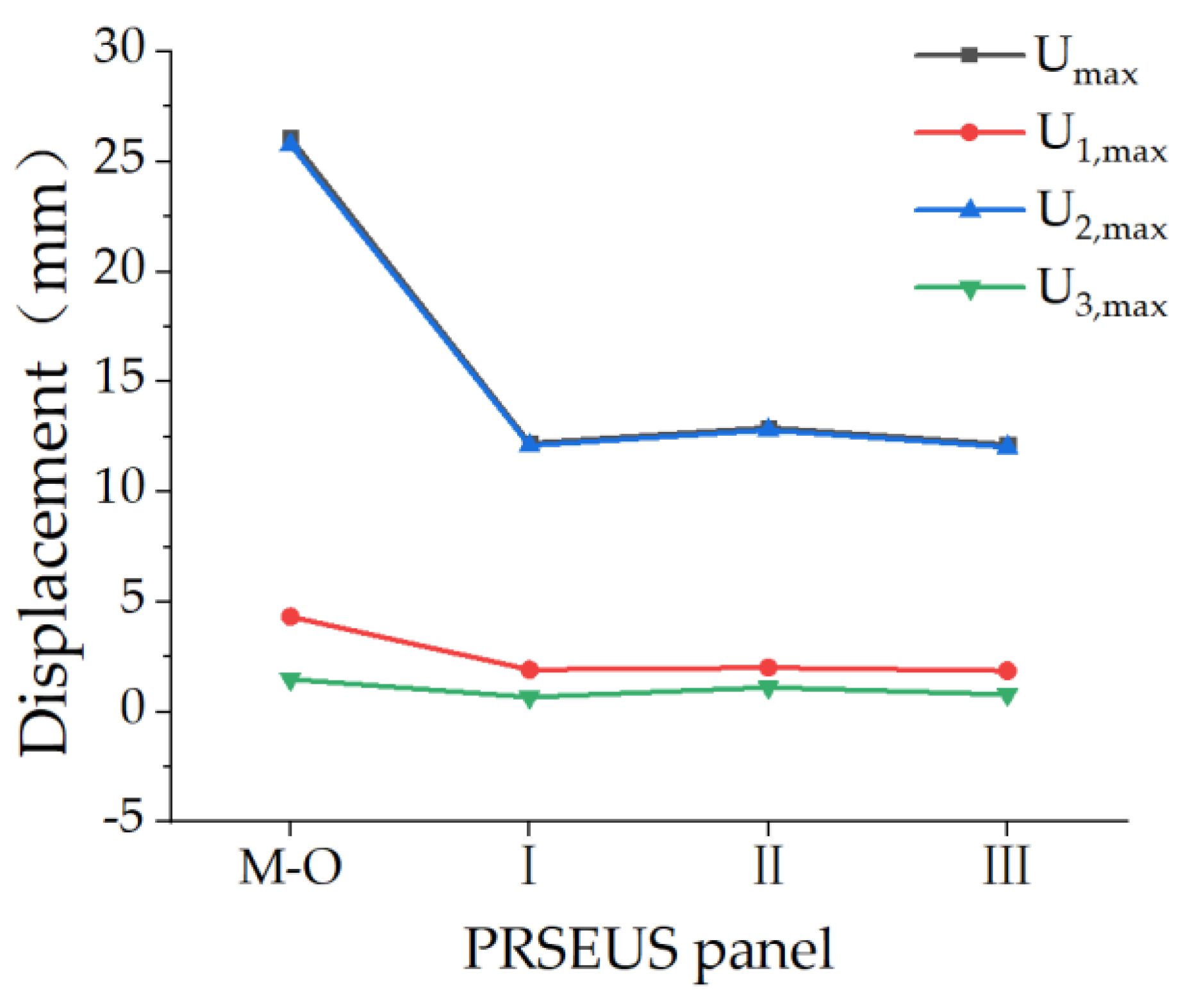
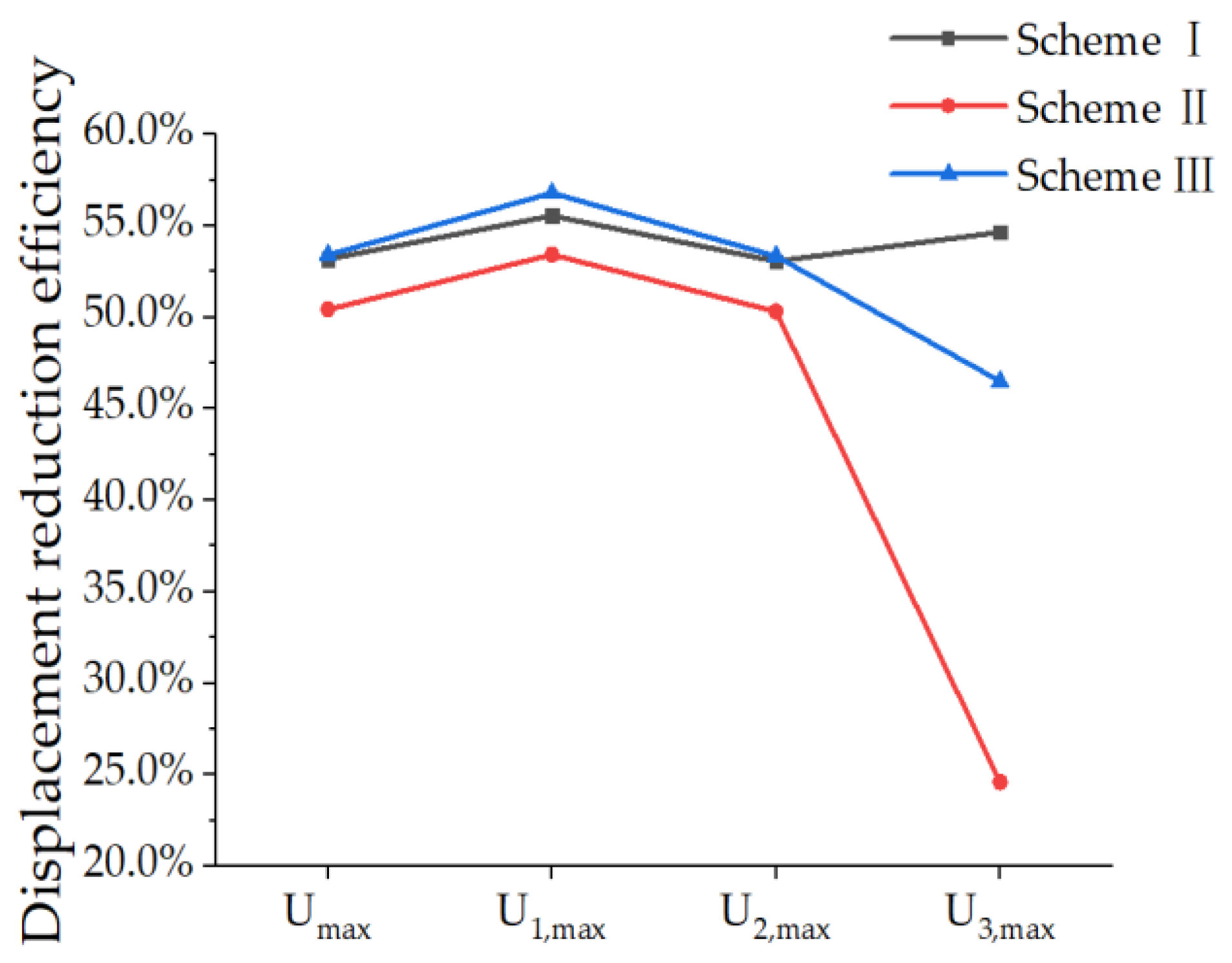
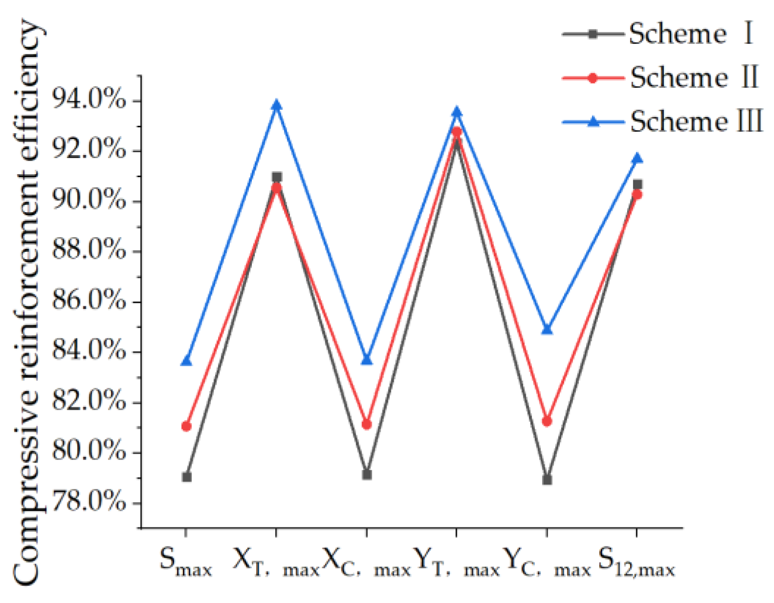
4.3. Compressive Load Analysis of Typical PRSEUS Panels and Reinforced Structures with a Mid-Sized Opening
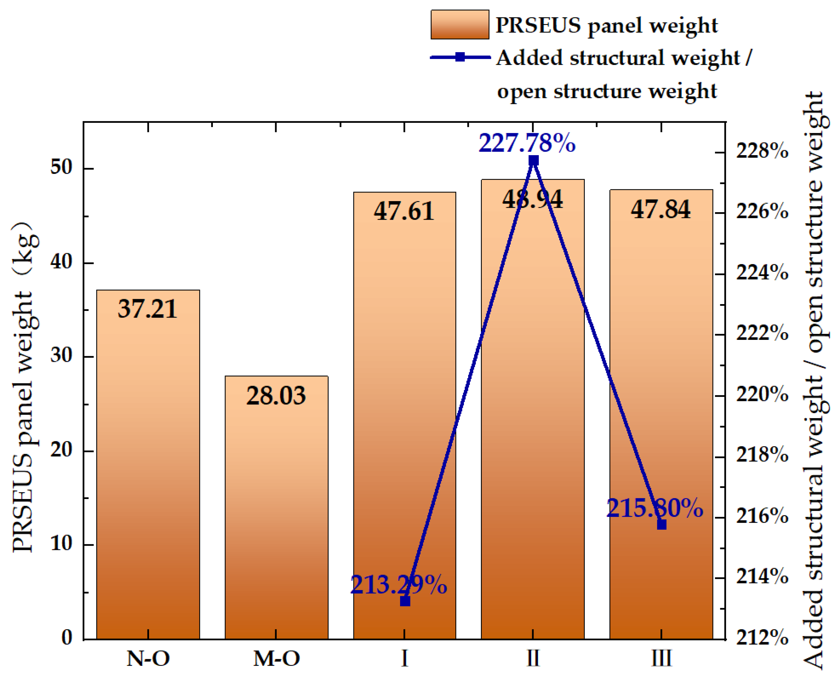
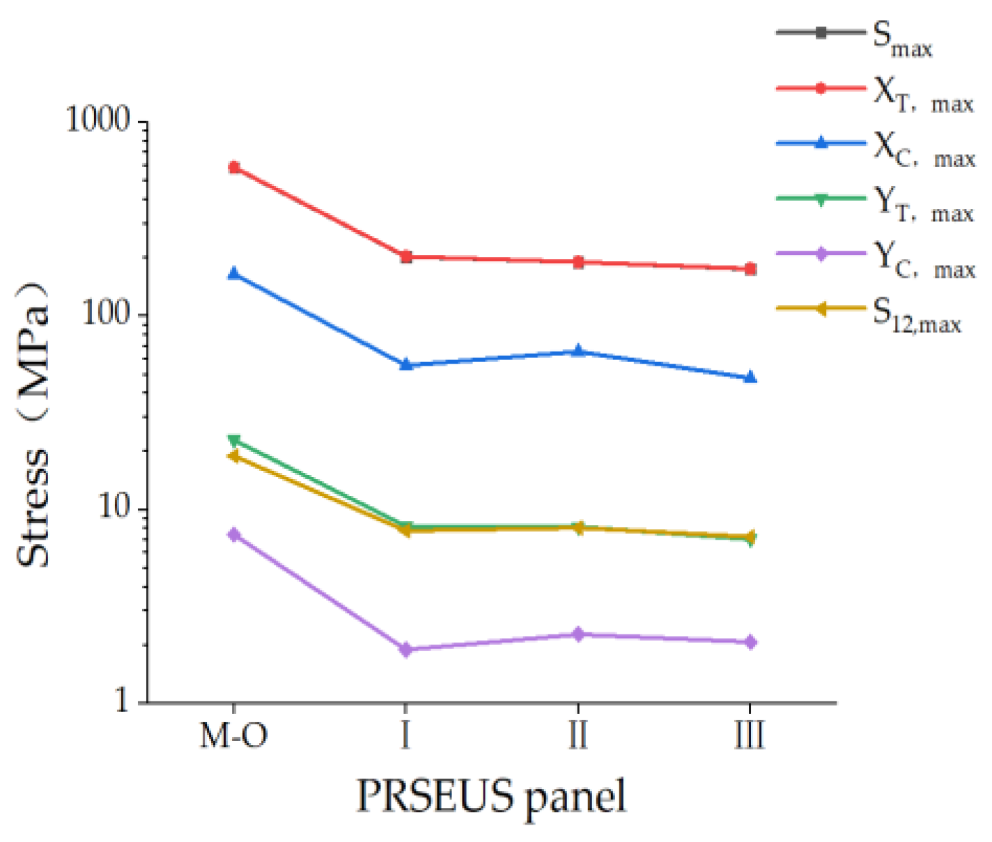
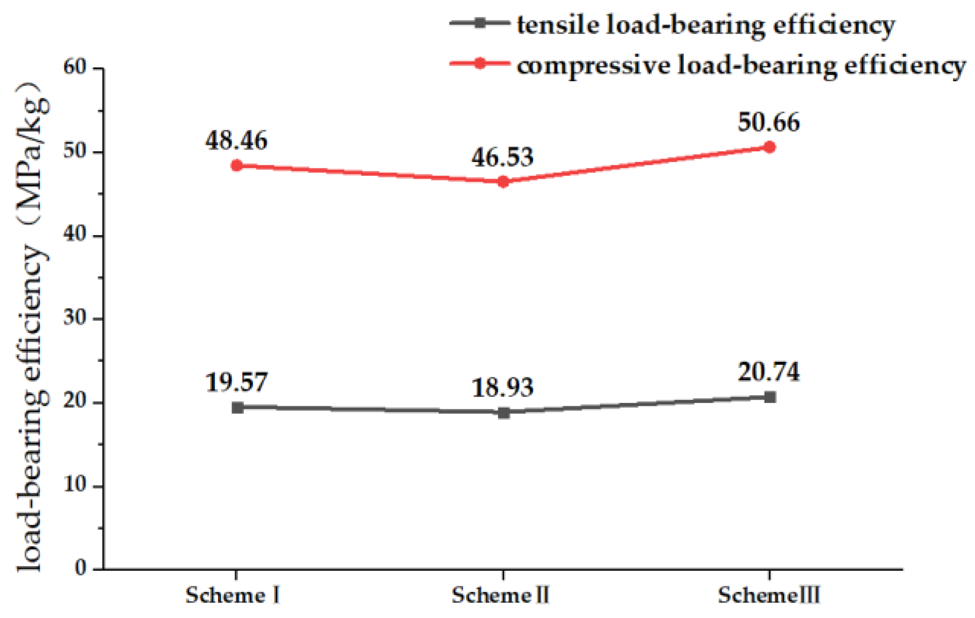
4.4. Load-Bearing Efficiency Analysis of Reinforced Structure of PRSEUS Panels with a Mid-Sized Opening
5. Summary
Author Contributions
Funding
Data Availability Statement
Conflicts of Interest
References
- Berger, R. Sustainable Aviation Fuels: The Best Solution to Large Sustainable Aircraft; Roland Berger: Munich, Germany, 2020. [Google Scholar]
- Ramon, E.; Sguazzo, C.; Moreira, P.M.G.P. A review of recent research on bio-based epoxy systems for engineering applications and potentialities in the aviation sector. Aerospace 2018, 5, 110. [Google Scholar] [CrossRef]
- Beck, A.J.; Hodzic, A.; Soutis, C.; Wilson, C.W. Influence of Implementation of Composite Materials in Civil Aircraft Industry on reduction of Environmental Pollution and Greenhouse Effect. IOP Conf. Ser. Mater. Sci. Eng. 2011, 26, 012015. [Google Scholar] [CrossRef]
- Beaumont, P.W.R. The structural integrity of composite materials and long-life implementation of composite structures. Appl. Compos. Mater. 2020, 27, 449–478. [Google Scholar] [CrossRef]
- Lee, J.; Gharghabi, P.; Boushab, D.; Ricks, T.M.; Lacy, T.E., Jr.; Pittman, C.U., Jr.; Mazzola, M.S.; Velicki, A. Artificial lightning strike tests on PRSEUS panels. Compos. Part B Eng. 2018, 154, 467–477. [Google Scholar] [CrossRef]
- Linton, K.A.; Velicki, A.; Hoffman, K.; Thrash, P.; Pickell, R.; Turley, R. PRSEUS Panel Fabrication Final Report; NASA/CR-2014-218149; NASA Technical Reports Server: Washington, DC, USA, 2014. Available online: http://ntrs.nasa.gov/search.jsp?R=20140006175 (accessed on 1 August 2024).
- Lanzi, L.; Bisagni, C. Post-Buckling experimental tests and numerical analyses on composite stiffened panels. In Proceedings of the 44th AIAA/ASME/ASCE/AHS/ASC Structures, Structural Dynamics, and Materials Conference, Norfolk, VA, USA, 7–10 April 2003; p. 1795. [Google Scholar]
- Velicki, A.; Thrash, P. Advanced structural concept development using stitched composites. In Proceedings of the 49th AIAA/ASME/ASCE/AHS/ASC Structures, Structural Dynamics, and Materials Conference, Schaumburg, IL, USA, 7–10 April 2008; p. 2329. [Google Scholar]
- Velicki, A.; Yovanof, N.; Baraja, J.; Linton, K.; Li, V.; Hawley, A.; Thrash, P.; DeCoux, S.; Pickell, R. Damage Arresting Composites for Shaped Vehicles-Phase II Final Report; National Aeronautics and Space Administration Langley Research Center: Hampton, VA, USA, 2011. [Google Scholar]
- Velicki, A.; Jegley, D. PRSEUS development for the hybrid wing body aircraft. In Proceedings of the AIAA Centennial of Naval Aviation Forum “100 Years of Achievement and Progress”, Virginia Beach, VA, USA, 21–22 September 2011; p. 7025. [Google Scholar]
- Ettoumi, S.; Zhang, Y.; Cui, B.; Zhou, J. Failure Initiation analysis of a PRSEUS BWB wing subjected to structural damage. Aerospace 2023, 10, 341. [Google Scholar] [CrossRef]
- Jain, L.K.; Mai, Y.W. Mode I delamination toughness of laminated composites with through-thickness reinforcement. Appl. Compos. Mater. 1994, 1, 1–17. [Google Scholar] [CrossRef]
- Dransfield, K.A.; Jain, L.K.; Mai, Y.W. On the effects of stitching in CFRPs—I. Mode I delamination toughness. Compos. Sci. Technol. 1998, 58, 815–827. [Google Scholar] [CrossRef]
- Bergan, A.; Bakuckas, J., Jr.; Awerbuch, J.; Tan, T.-M. Assessment of damage containment features of a full-scale PRSEUS fuselage panel. Compos. Struct. 2014, 113, 174–185. [Google Scholar] [CrossRef]
- Lovejoy, A.; Rouse, M.; Linton, K.; Li, V.P. Pressure testing of a minimum gauge PRSEUS panel. In Proceedings of the 52nd AIAA/ASME/ASCE/AHS/ASC Structures, Structural Dynamics and Materials Conference, Denver, CO, USA, 4–7 April 2011; p. 1813. [Google Scholar]
- Yovanof, N.; Lovejoy, A.E.; Baraja, J.; Gould, K. Design, analysis and testing of a PRSEUS pressure cube to investigate assembly joints. In Proceedings of the 2012 Aircraft Airworthiness and Sustainment Conference, Baltimore, MD, USA, 2–5 April 2012. NF1676L-13922. [Google Scholar]
- Li, V.; Velicki, A. Advanced PRSEUS structural concept design and optimization. In Proceedings of the 12th AIAA/ISSMO Multidisciplinary Analysis and Optimization Conference, Victoria, BC, Canada, 10–12 September 2008; p. 5840. [Google Scholar]
- Yovanof, N.; Velicki, A.; Li, V. Advanced structural stability analysis of a non-circular, BWB-shaped vehicle. In Proceedings of the 50th AIAA/ASME/ASCE/AHS/ASC Structures, Structural Dynamics, and Materials Conference, Palm Springs, CA, USA, 4–7 May 2009. [Google Scholar]
- Horton, B.; Song, Y.; Bayandor, J. Numerical investigation of stringer-frame intersections for stitched aerospace structures. In Proceedings of the 2018 AIAA/ASCE/AHS/ASC Structures, Structural Dynamics, and Materials Conference, Kissimmee, KL, USA, 8–12 January 2018; p. 0230. [Google Scholar]
- Velicki, A.; Thrash, P.; Jegley, D. Airframe development for the hybrid wing body aircraft. In Proceedings of the 47th AIAA aerospace Sciences Meeting Including the New Horizons Forum and Aerospace Exposition, Orlando, FL, USA, 5–8 January 2019; p. 932. [Google Scholar]
- Jegley, D.C.; Lovejoy, A.E. The Use of the STAGS Finite Element Code in Stitched Structures Development. In Proceedings of the 55th AIAA/ASMe/ASCE/AHS/SC Structures, Structural Dynamics, and Materials Conference, National Harbor, MD, USA, 13–17 January 2014; p. 0845. [Google Scholar]
- Jegley, D.C. Improving strength of postbuckled panels through stitching. Compos. Struct. 2007, 80, 298–306. [Google Scholar] [CrossRef]
- Sanz-Douglass, G.J. Parametric study of influence of stiffener variables on postbuckling response of frame-stiffened composite panels. Master’s Thesis, San Diego State University, San Diego, CA, USA, 2015. [Google Scholar]
- Leone, F.A.; Jegley, D.C.; Linton, K.A. Compressive loading and modeling of stitched composite stiffeners. In Proceedings of the 57th AIAA/ASCE/AHS/ASC Structures, Structural Dynamics, and Materials Conference, San Diego, CA, USA, 4–8 January 2016; p. 2179. [Google Scholar]
- Lovejoy, A.E.; Leone, F.A. Tension and Bending Testing of an Integral T-cap for Stitched Composite Airframe Joints. In Proceedings of the 57th AIAA/ASCE/AHS/ASC Structures, Structural Dynamics, and Materials Conference, San Diego, CA, USA, 4–8 January 2016; p. 2180. [Google Scholar]
- Jegley, D.C. Behavior of Frame-Stiffened Composite Panels with Damage. In Proceedings of the 54th AIAA/ASME/ASCE/AHS/ASC Structures, Structural Dynamics, and Materials Conference, Boston, MA, USA, 8–11 April 2013; p. 1738. [Google Scholar]
- Przekop, A. Repair concepts as design constraints of a stiffened composite PRSEUS panel. In Proceedings of the 53rd AIAA/ASME/ASCE/AHS/ASC Structures, Structural Dynamics and Materials Conference, 20th AIAA/ASME/AHS Adaptive Structures Conference 14th AIAA, Honolulu, HI, USA, 23–26 April 2012; p. 1444. [Google Scholar]
- Zhang, Y.; Wu, Y. Research on Setting Method of Neutral Schemee Offset of Shell Element in PRSEUS Panel Structure Modeling. In Proceedings of the 2021 12th International Conference on Mechanical and Aerospace Engineering (ICMAE), Athens, Greece, 16–19 July 2021; pp. 91–95. [Google Scholar]
- Zhao, L.; Wang, Y.; Zhang, J.; Gong, Y.; Hu, N.; Li, N. XFEM-based model for simulating zigzag delamination growth in laminated composites under mode I loading. Compos. Struct. 2017, 160, 1155–1162. [Google Scholar] [CrossRef]
- Hossain, K.M.A.; Mol, L.K.; Anwar, M.S. Axial load behaviour of pierced profiled composite panels with strength enhancement devices. J. Constr. Steel Res. 2015, 110, 48–64. [Google Scholar] [CrossRef]
- Soutis, C. Compressive strength of composite laminates with an open hole: Effect of ply blocking. J. Compos. Mater. 2013, 47, 2503–2512. [Google Scholar] [CrossRef]
- Acharya, S.R.; Sivakumaran, K.S.; Young, B. Reinforcement schemes for cold-formed steel joists with a large web opening in shear zone—An experimental investigation. Thin-Paneled Struct. 2013, 72, 28–36. [Google Scholar] [CrossRef]
- Rao, Y.S.; Mohan, N.S.; Shetty, N.; Shivamurthy, B. Drilling and structural property study of multi-layered fiber and fabric reinforced polymer composite-a review. Mater. Manuf. Process. 2019, 34, 1549–1579. [Google Scholar] [CrossRef]
- Yao, L.; Zhao, M.; Wan, X. Parameter analysis of composite laminates with patched reinforcement based on CDM-CZM. Acta Aeronaut. Astronaut. Sin. 2012, 33, 666–671. [Google Scholar]
- Deng, J.; Zhou, G.; Bordas, S.P.; Xiang, C. Numerical evaluation of buckling behaviour induced by compression on patch-repaired composites. Compos. Struct. 2017, 168, 582–596. [Google Scholar] [CrossRef]
- Wang, Y.; Jiang, Y.; Yue, Z. Experiment and modeling of repaired composite lamina under compression. J. Mech. Strength 2006, 28, 869–873. [Google Scholar] [CrossRef]
- Han, X.P.; Li, L.X.; Zhu, X.P.; Yue, Z.F. Experimental study on the stitching reinforcement of composite laminates with a circular hole. Compos. Sci. Technol. 2008, 68, 1649–1653. [Google Scholar] [CrossRef]
- Jiang, H.; Ren, Y. CFRP-patching enhancement on open-hole CFRP panel with micro/nanofillers-modified adhesive interface: Experimental and numerical simulation. Compos. Sci. Technol. 2022, 218, 109180. [Google Scholar] [CrossRef]


| Parameter | Size/mm |
|---|---|
| PESUES panel board length | 2021.36 |
| PESUES panel width | 2204.80 |
| Frames’ spacing | 475.00–487.50 |
| Stringer spacing | 161.00 |
| Frame foam height | 120.00 |
| Width of the frame tear straps and flanges | 92.70 |
| Stringer web height | 35.00 |
| Radius of the pultruded rod | 4.76 |
| Width of the stringer tear straps and flanges | 80.00 |
| Material | Parameter | Symbol | Value | Unit |
|---|---|---|---|---|
| Foam core | Young’s modulus | E | 144.79 | MPa |
| Poisson’s Ratio | V | 0.45 | - | |
| Density | ρ | 99.9 | kg/m3 | |
| Pultruded pod | Young’s modulus | E | 126,932.48 | MPa |
| Poisson’s Ratio | V | 0.3 | - | |
| Density | ρ | 1600 | kg/m3 |
| Parameter | Symbol | Value | Unit |
|---|---|---|---|
| Young’s modulus | E1 | 195,000 | MPa |
| E2 | 8580 | MPa | |
| E3 | 8580 | MPa | |
| Poisson’s Ratio | μ12 | 0.33 | - |
| μ13 | 0.33 | - | |
| μ23 | 0.48 | - | |
| Shear Modulus | G12 | 4570 | MPa |
| G13 | 4570 | MPa | |
| G23 | 2900 | MPa | |
| Density | ρ | 1600 | kg/m3 |
| Longitudinal tensile and compressive strength | XT | 3071 | MPa |
| XC | 1747 | MPa | |
| Transverse tensile and compressive strength | YT | 88 | MPa |
| YC | 271 | MPa | |
| Shear strength | S12 | 143 | MPa |
| Component | Lamina | Lamina Thickness | Lay Up |
|---|---|---|---|
| Skin | 9 | 0.15 | [45, −45, 0, 0, 90, 0, 0, −45, 45]T |
| Frame web | 9 | 0.20 | [45, −45, 0, 0, 90, 0, 0, −45, 45]T |
| Frame flanges | 9 | 0.20 | [45, −45, 0, 0, 90, 0, 0, −45, 45]T |
| Frame tear straps | 9 | 0.15 | [45, −45, 0, 0, 90, 0, 0, −45, 45]T |
| Stringer web | 9 | 0.25 | [45, −45, 0, 0, 90, 0, 0, −45, 45]T |
| Stringer flanges | 9 | 0.15 | [45, −45, 0, 0, 90, 0, 0, −45, 45]T |
| Stringer tear straps | 9 | 0.15 | [45, −45, 0, 0, 90, 0, 0, −45, 45]T |
| Parameter | Lower Limit | Upper Limit |
|---|---|---|
| Mesh size | 6 mm | 30 mm |
| Jacobian | 0.60 | - |
| Aspect ratio | - | 5 |
| Warping factor | - | 5° |
| Quadrilateral element angle | 40° | 135° |
| Triangle element angle | 30° | 120° |
| Influencing Factors | Scheme | Scheme Model |
|---|---|---|
| Influence of panel opening’s symmetry | a | Opening symmetry side to side |
| b | Opening symmetry up and down | |
| Influence of panel chamber | c | Curved PRSEUS panel |
| d | Flat PRSEUS panel | |
| Siding direction influence | e | Flat 0° laminated panels |
| f | Flat 90° laminated panels | |
| Ply direction and structure influence | g | 0° ply laminate |
| h | 90° ply laminate |
| Scheme | Reinforcement Method Scheme |
|---|---|
| A | Mouth reinforcement |
| B | Boss reinforcement |
| C | Mouth and boss reinforcement |
| D | Frame and mouth reinforcement |
| E | Mouth and boss reinforcement |
| PRSEUS Panels | Smax (MPa) | XT, max (MPa) | XC, min (MPa) | YT, max (MPa) | YC, min (MPa) | S12, max (MPa) |
|---|---|---|---|---|---|---|
| Non-opening | 198.6 | 202.4 | 70.8 | 10.9 | 3.3 | 9.7 |
| Small opening | 1108.0 | 1111.0 | 239.3 | 47.3 | 10.1 | 8.3 |
| Scheme A | 393.0 | 343.4 | 141.8 | 18.3 | 5.9 | 8.1 |
| Scheme B | 641.9 | 656.2 | 255.3 | 36.6 | 12.3 | 9.6 |
| Scheme C | 491.1 | 403.1 | 164.0 | 21.6 | 6.1 | 9.1 |
| Scheme D | 320.8 | 310.7 | 141.3 | 13.8 | 5.8 | 17.0 |
| Scheme E | 569.1 | 577.2 | 290.3 | 32.17 | 10.3 | 10.41 |
| Scheme | Tensile Reinforcement Efficiency of PRSEUS Panels | |||||
|---|---|---|---|---|---|---|
| Smax | XT, max | XC, min | YT, max | YC, min | S12, max | |
| A | 64.53% | 69.09% | 40.74% | 61.42% | 41.57% | 2.12% |
| B | 42.07% | 40.94% | −6.69% | 22.68% | −21.80% | −15.02% |
| C | 55.68% | 63.72% | 31.47% | 54.38% | 39.11% | −9.47% |
| D | 71.05% | 72.03% | 40.95% | 70.76% | 42.15% | −104.47% |
| E | 48.64% | 48.05% | −21.31% | 31.99% | −2.08% | −25.21% |
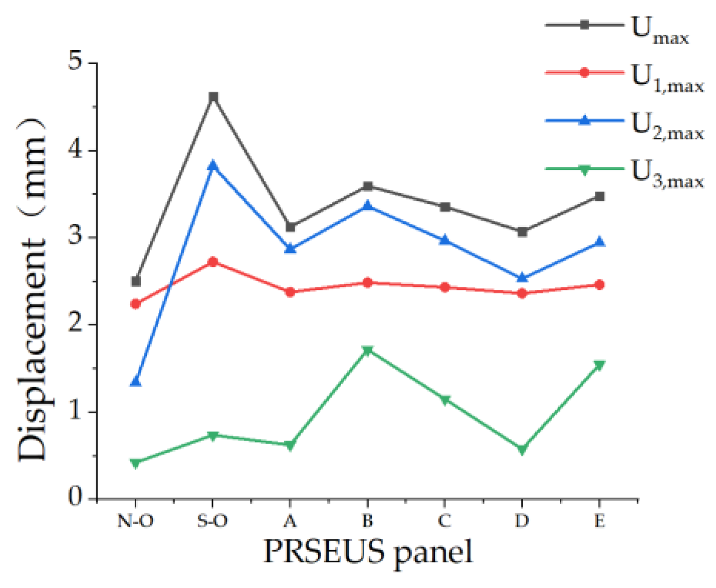
| PRSEUS Panels | Umax (mm) | U1, max (mm) | U2, max (mm) | U3, max (mm) |
|---|---|---|---|---|
| Non-opening | 2.505 | 2.244 | 1.341 | 0.426 |
| Small opening | 4.626 | 2.726 | 3.825 | 0.741 |
| Scheme A | 3.127 | 2.380 | 2.870 | 0.627 |
| Scheme B | 3.597 | 2.489 | 3.365 | 1.720 |
| Scheme C | 3.359 | 2.435 | 2.968 | 1.153 |
| Scheme D | 3.073 | 2.366 | 2.534 | 0.580 |
| Scheme E | 3.484 | 2.464 | 2.947 | 1.549 |
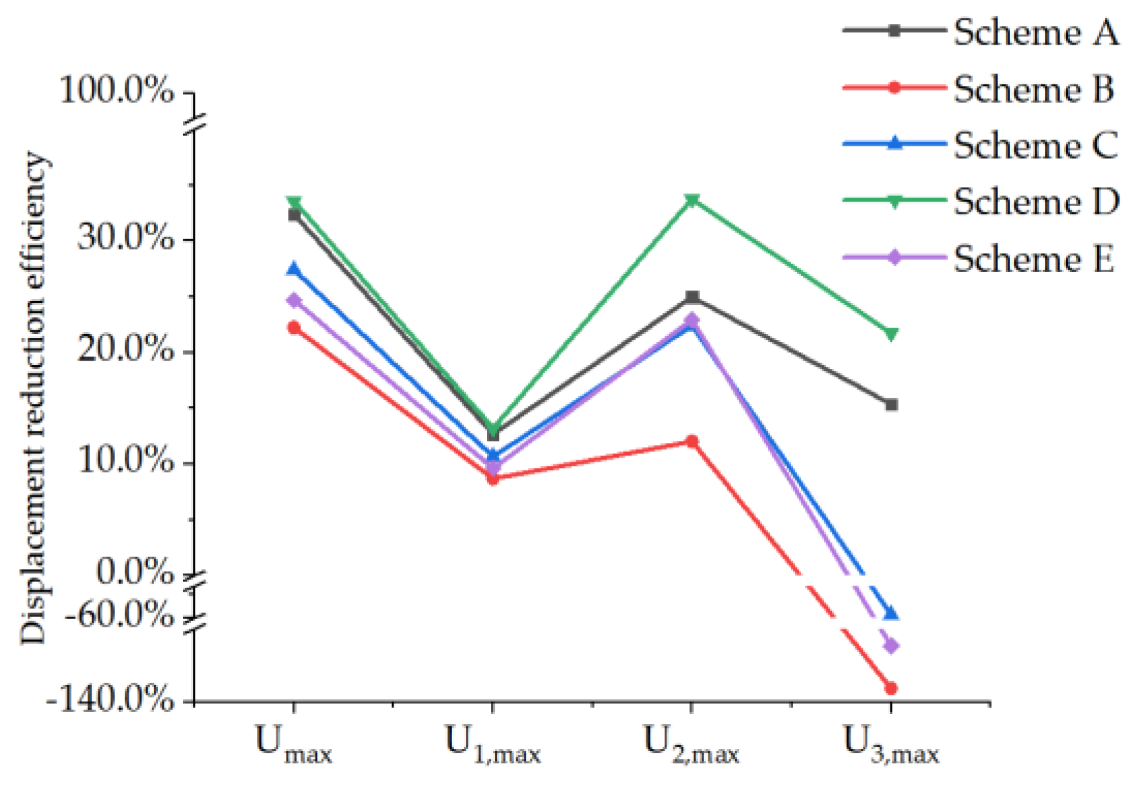
| Scheme | Displacement-Reduction Efficiency | |||
|---|---|---|---|---|
| Umax | U1, max | U2, max | U3, max | |
| A | 32.40% | 12.69% | 24.97% | 15.38% |
| B | 22.24% | 8.69% | 12.03% | −132.12% |
| C | 27.39% | 10.67% | 22.41% | −55.60% |
| D | 33.57% | 13.21% | 33.75% | 21.73% |
| E | 24.69% | 9.61% | 22.95% | −109.42% |
| PRSEUS Panels | Smax (MPa) | XT, max (MPa) | XC, min (MPa) | YT, max (MPa) | YC, min (MPa) | S12, max (MPa) |
|---|---|---|---|---|---|---|
| Non-opening | 263.1 | 210.2 | 239.1 | 15.0 | 12.5 | 15.6 |
| Small opening | 933.2 | 776.5 | 929.0 | 45.5 | 36.0 | 55.9 |
| Scheme A | 463.4 | 315.4 | 402.4 | 19.7 | 21.3 | 20.4 |
| Scheme B | 516.1 | 390.3 | 529.0 | 23. 9 | 30.3 | 39.0 |
| Scheme C | 616.2 | 310.7 | 534.0 | 17.8 | 28.5 | 28.6 |
| Scheme D | 406.8 | 323.0 | 362.0 | 19.6 | 19.4 | 20.6 |
| Scheme E | 530.5 | 396.5 | 543.8 | 23.95 | 39.64 | 46.15 |
| Scheme | Compressive Reinforcement Efficiency of PRSEUS Panels | |||||
|---|---|---|---|---|---|---|
| Smax | XT, max | XC, min | YT, max | YC, min | S12, max | |
| A | 50.34% | 59.38% | 56.68% | 56.62% | 40.85% | 63.51% |
| B | 44.70% | 49.74% | 43.06% | 47.47% | 15.94% | 30.23% |
| C | 33.97% | 59.99% | 42.52% | 60.88% | 20.83% | 48.93% |
| D | 56.41% | 58.40% | 61.03% | 56.84% | 46.04% | 63.13% |
| E | 43.15% | 48.94% | 41.46% | 47.34% | −10.08% | 17.44% |
| PRSEUS Panels | Umax (mm) | U1, max (mm) | U2, max (mm) | U3, max (mm) |
|---|---|---|---|---|
| Non-opening | 4.766 | 2.350 | 4.231 | 0.697 |
| Small opening | 13.050 | 3.521 | 4.858 | 2.310 |
| Scheme A | 4.682 | 2.452 | 4.106 | 0.907 |
| Scheme B | 8.219 | 2.823 | 7.707 | 2.441 |
| Scheme C | 4.949 | 2.543 | 3.808 | 1.476 |
| Scheme D | 5.154 | 2.480 | 4.623 | 1.003 |
| Scheme E | 8.307 | 2.824 | 3.882 | 3.080 |
| Scheme | Displacement-Reduction Efficiency of PRSEUS Panels | |||
|---|---|---|---|---|
| Umax | U1, max | U2, max | U3, max | |
| A | 64.12% | 30.36% | 15.48% | 60.74% |
| B | 37.02% | 19.82% | −58.65% | −5.67% |
| C | 62.08% | 27.78% | 21.61% | 36.10% |
| D | 60.51% | 29.57% | 4.84% | 56.58% |
| E | 36.34% | 19.80% | 20.01% | −33.33% |
| Scheme | Reinforcement Method Scheme |
|---|---|
| I | Grid reinforcement |
| II | Grid, pads, and stiffeners reinforcement |
| III | Cross-shaped reinforcement |
| PRSEUS Panels | Smax (MPa) | XT, max (MPa) | XC, min (MPa) | YT, max (MPa) | YC, min (MPa) | S12, max (MPa) |
|---|---|---|---|---|---|---|
| Non-opening | 36.11 | 36.80 | 13.08 | 2.006 | 0.634 | 2.262 |
| Mid-sized opening | 586 | 587.2 | 164.8 | 22.91 | 7.439 | 18.95 |
| Scheme I | 202.9 | 203.1 | 55.55 | 8.217 | 1.893 | 7.787 |
| Scheme II | 190.2 | 190.2 | 65.62 | 8.175 | 2.278 | 8.064 |
| Scheme III | 175.1 | 175.4 | 47.84 | 7.059 | 2.079 | 7.252 |
| Scheme | Tensile Reinforcement Efficiency of PRSEUS Panels | |||||
|---|---|---|---|---|---|---|
| Smax | XT, max | XC, min | YT, max | YC, min | S12, max | |
| I | 65.38% | 65.41% | 66.29% | 64.13% | 74.55% | 58.91% |
| II | 67.54% | 67.61% | 60.18% | 64.32% | 69.38% | 57.45% |
| III | 70.12% | 70.13% | 70.97% | 69.19% | 72.05% | 61.73% |
| PRSEUS Panels | Umax (mm) | U1, max (mm) | U2, max (mm) | U3, max (mm) |
|---|---|---|---|---|
| Non-opening | 0.500 | 0.416 | 0.307 | 0.084 |
| Mid-sized opening | 26.08 | 4.328 | 25.78 | 1.484 |
| Scheme I | 12.2 | 1.924 | 12.1 | 0.673 |
| Scheme II | 12.93 | 2.016 | 12.81 | 1.119 |
| Scheme III | 0.500 | 0.416 | 0.307 | 0.084 |
| Scheme | Displacement-Reduction Efficiency of PRSEUS Panels | |||
|---|---|---|---|---|
| Umax | U1, max | U2, max | U3, max | |
| I | 53.18% | 55.55% | 53.06% | 54.65% |
| II | 50.42% | 53.42% | 50.31% | 24.60% |
| III | 53.41% | 56.79% | 53.34% | 46.50% |
| PRSEUS Panels | Smax (MPa) | XT, max (MPa) | XC, min (MPa) | YT, max (MPa) | YC, min (MPa) | S12, max (MPa) |
|---|---|---|---|---|---|---|
| Non-opening | 35.87 | 13.04 | 36.56 | 0.641 | 2.009 | 2.258 |
| Mid-sized opening | 1200 | 893.3 | 1206 | 42.6 | 52.19 | 100.6 |
| Scheme I | 251.2 | 80.3 | 251.5 | 3.267 | 10.99 | 9.331 |
| Scheme II | 227.1 | 84.29 | 227.3 | 3.072 | 9.771 | 9.761 |
| Scheme III | 196.4 | 55.1 | 196.7 | 2.743 | 7.891 | 8.33 |
| Scheme | Tensile Reinforcement Efficiency of PRSEUS Panels | |||||
|---|---|---|---|---|---|---|
| Smax | XT, max | XC, min | YT, max | YC, min | S12, max | |
| I | 79.07% | 91.01% | 79.15% | 92.33% | 78.94% | 90.72% |
| II | 81.08% | 90.56% | 81.15% | 92.79% | 81.28% | 90.30% |
| III | 83.63% | 93.83% | 83.69% | 93.56% | 84.88% | 91.72% |
| PRSEUS Panels | Umax (mm) | U1, max (mm) | U2, max (mm) | U3, max (mm) |
|---|---|---|---|---|
| Non-opening | 0.529 | 0.418 | 0.349 | 0.086 |
| Mid-sized opening | 67.37 | 10.66 | 67.04 | 4.229 |
| Scheme I | 16.78 | 2.478 | 16.66 | 0.924 |
| Scheme II | 18.69 | 2.703 | 18.56 | 1.503 |
| Scheme III | 16.70 | 2.407 | 16.57 | 0.976 |
| Scheme | Displacement-Reduction Efficiency of PRSEUS Panels | |||
|---|---|---|---|---|
| Umax | U1, max | U2, max | U3, max | |
| I | 75.09% | 76.75% | 75.15% | 78.15% |
| II | 72.26% | 74.64% | 72.32% | 64.46% |
| III | 75.21% | 77.42% | 75.28% | 76.92% |
Disclaimer/Publisher’s Note: The statements, opinions and data contained in all publications are solely those of the individual author(s) and contributor(s) and not of MDPI and/or the editor(s). MDPI and/or the editor(s) disclaim responsibility for any injury to people or property resulting from any ideas, methods, instructions or products referred to in the content. |
© 2024 by the authors. Licensee MDPI, Basel, Switzerland. This article is an open access article distributed under the terms and conditions of the Creative Commons Attribution (CC BY) license (https://creativecommons.org/licenses/by/4.0/).
Share and Cite
Zhang, Y.; Zhang, T.; Zhou, J.; Cui, B.; Chen, F. The Design and Analysis of Reinforcement Schemes for Pultruded Rod Stitched Efficient Unitized Structure Open-Panel Structures. Aerospace 2024, 11, 726. https://doi.org/10.3390/aerospace11090726
Zhang Y, Zhang T, Zhou J, Cui B, Chen F. The Design and Analysis of Reinforcement Schemes for Pultruded Rod Stitched Efficient Unitized Structure Open-Panel Structures. Aerospace. 2024; 11(9):726. https://doi.org/10.3390/aerospace11090726
Chicago/Turabian StyleZhang, Yongjie, Tongxin Zhang, Jingpiao Zhou, Bo Cui, and Fangyu Chen. 2024. "The Design and Analysis of Reinforcement Schemes for Pultruded Rod Stitched Efficient Unitized Structure Open-Panel Structures" Aerospace 11, no. 9: 726. https://doi.org/10.3390/aerospace11090726
APA StyleZhang, Y., Zhang, T., Zhou, J., Cui, B., & Chen, F. (2024). The Design and Analysis of Reinforcement Schemes for Pultruded Rod Stitched Efficient Unitized Structure Open-Panel Structures. Aerospace, 11(9), 726. https://doi.org/10.3390/aerospace11090726