Article

Effects of Fuel Penetration on the RDE Performance with JISC Injector Configuration

Department of Aerospace Engineering, Pusan National University, Busan 46241, Republic of Korea
*
Author to whom correspondence should be addressed.
Aerospace 2024, 11(9), 752; https://doi.org/10.3390/aerospace11090752
Submission received: 12 August 2024 / Revised: 8 September 2024 / Accepted: 10 September 2024 / Published: 13 September 2024
(This article belongs to the Special Issue Aerospace Combustion Engineering (2nd Edition))

Abstract

:
This study investigates the operational characteristics of the Rotating Detonation Engine (RDE), with a focus on fuel injector design. Inspired by the similarity between the fuel injection structure of RDE and the Jet in Supersonic Crossflow (JISC) of a scramjet, experimental research on fuel injectors with jet penetration was conducted. Five injectors were designed, each with a fixed fuel injection area or injection hole diameter. Experiments determined practical injection areas, and an empirical correlation was used to calculate jet penetration heights. Under conditions of a total mass flow rate of 105 ± 5 g/s and an equivalence ratio of 1.05 ± 0.1, combustion modes were analyzed. Initial detonation occurrence was assessed through pressure history, with a detailed analysis via image post-processing. The results indicated that the injector D4N15, with the highest jet penetration height, exhibited deflagration, while D4N23 showed chaotic propagation. The injector D2N60 demonstrated relatively unstable behavior in sustained detonation cases. Thrust comparisons revealed that D4N30, with wider hole spacing and higher jet penetration height, exhibited approximately 12.5% higher specific impulse compared to D1N240. These outcomes confirm the significant impact of jet penetration height and hole spacing on detonation propagation and engine performance.

1. Introduction

Detonation-based propulsion is considered a game-changer to replace deflagration-based propulsion, which faces limitations in performance improvement. Kailasanath et al. [1,2] provide a comprehensive overview of recent advancements in Pulse Detonation Engines (PDEs), with a focus on developments in fuel mixing, detonation initiation, and the challenges associated with accurately estimating system performance for aerospace applications. Wolański et al. [3] examine the advantages and challenges of detonation propulsion, focusing on recent advancements in PDE and Rotating Detonation Engines (RDEs) within aerospace applications. Li et al. [4] look at recent advancements in detonation propulsion, specifically focusing on the design and aerospace applications of RDE and PDE. Lu et al. [5] review the challenges and advancements in RDE, highlighting experimental difficulties, modeling approaches, and the potential for enhanced efficiency in aerospace propulsion systems. Kim et al. [6,7] review recent research on RDE and its potential to enhance propulsion efficiency through pressure gain combustion (PGC). Unlike deflagration, which has a static combustion process, research is being actively carried out to utilize detonation, which has the potential of PGC with the process of constant volume combustion (CVC). To advance the application of detonation-based propulsion, numerical analysis studies have been conducted to provide a deeper understanding of detonation behavior. Choi et al. [8] address the challenges of simulating detonation cell structure in gaseous detonations, focusing on the effects of grid resolution, time steps, domain lengths, and boundary conditions. They recommend using at least five grid points within the heat-release zone of a steady Zel’dovich–von Neumann–Döring wave to accurately model detonation wave–front dynamics, offering crucial guidance for improving numerical simulations. Hishida et al. [9] numerically stabilized a rotating detonation front at near-Chapman–Jouguet (CJ) velocity, revealing smaller cell sizes (3 to 3.5 mm) near solid walls due to triple-shock collisions, and larger cell sizes (4 mm) in unconfined regions. In addition, Choi et al. [10], Pavalavanni et al. [11], and Cho et al. [12] conducted a detonation cell structure study.
Theoretically, four types of detonation-based propulsion engines have PGC advantages. Rosato et al. [13] investigate stabilized detonation waves for hypersonic propulsion, demonstrating successful initiation and emphasizing the importance of mixture composition and heat release for maintaining stability. Ishihara et al. [14] focus on developing an RDE for rocket propulsion, demonstrating successful long-duration combustion and advancing RDE technology for aerospace applications. Zonglin et al. [15] develop criteria for stable hypersonic propulsion, focusing on scramjet engines, with experimental verification demonstrating successful detonation-wave stabilization. Yamaguchi et al. [16] explore a novel Reflective Shuttling Detonation Combustor (RSDC), demonstrating stable detonation waves in a fan-shaped combustor, highlighting its potential for enhancing supersonic combustion efficiency in aerospace propulsion technologies. There are (1) the PDE, requiring periodic mechanical devices; (2) the RDE, propagated along the combustion chamber channel; (3) the Oblique Detonation-Wave Engine (ODWE), using standing detonation in hypersonic propulsion engine; and (4) the Shuttling Transverse Combustor (STC), which is capable of periodic operation of a two-dimensional shape. Among the four types of detonation-based propulsion engines, the PDE has been a prominent focus, operating on the principle of a detonation-wave propagation through a tube. Ma et al. [17,18] conducted numerical studies on PDEs, developing various concepts, including single-tube and multitube configurations. Kim et al. [19] experimentally investigated multitube PDEs, demonstrating that increasing the operating frequency generally enhances thrust and specific impulse, though instability was observed at very high frequencies (200 Hz). Additionally, their findings indicated that higher equivalence ratios negatively impact performance. In a separate study, Ma et al. [20,21] explored further methods to optimize PDE performance.
However, recent research has increasingly focused on the RDE, driven by its superior performance compared to the PDE. Studies have explored the application of RDEs, leveraging their pressure-gain characteristics for use in gas turbines and rocket engines. Yi et al. [22] investigated the performance of a continuous RDE through numerical simulations, finding that it delivers stable thrust and surpasses traditional PDEs in total specific impulse. The study also showed that engine performance is highly sensitive to injection conditions but less influenced by chamber length and detonation-wave count. Jones et al. [23] theoretically confirmed that implementing PGC in current turbofan engines can reduce aircraft fuel consumption by 4–9%. Additionally, Frolov et al. [24] reported a maximum 15% increase in combustor voltage through numerical studies. Sousa et al. [25] and Strakey et al. [26] showed a 5% increase in thermal efficiency through similar studies. Experimental work by Wolański et al. [27] confirmed a 5% reduction in Specific Fuel Consumption (SFC) when applied to an unoptimized GTD-350 turboprop engine. Frolov et al. [28] found that RDEs achieved 7–13% higher efficiency than depletion of combustors.
For rocket engines, various combustor geometries have been explored to increase technical readiness through sounding rockets and space demonstrations, aiming to reduce combustor volume and weight. Teasley et al. [29] from NASA’s Marshall Space Flight Center conducted RDE combustion experiments, achieving approximately 32 kN of thrust using LOX/GH2 and LOX/LCH4 propellants with water or regenerative cooling. Notably, a LOX/LCH4 test resulted in 113 s of combustion, yielding a 40% reduction in combustor length compared to a static pressure combustor. Goto et al. [30] at Nagoya University performed a 500 N thrust RDE experiment in a space environment, where JAXA’s S-520 rocket reached an altitude of over 100 km, burning for 6 s after separation. Additionally, a PDE mounted in the second stage operated 15 times at 2 Hz but was constrained by a weight ratio limit of 0.07. Kawalec et al. [31] at the Lukasiewicz Institute of Aviation Research explored RDEs as propulsion for sounding rockets, utilizing LN2O/LC3H8 propellants in annular, disk, and cone configurations. Their experiments, which employed a 215 N RDE with regenerative cooling, achieved an altitude of 450 m, even during the inertial flight phase. Further research by Ishihara et al. [32] using GC2H4/GO2 propellants demonstrated that detonation waves were sustained with a combustion chamber length of 0 mm, achieving 97% to 100% of the theoretical specific impulse.
To achieve practical pressure gain, four critical operational processes must be fulfilled [33]: (1) provision of pre-mixed propellants; (2) efficient delivery of propellants into the combustion chamber; (3) initiation and maintenance of combustion through CJ detonation, avoiding deflagration; and (4) prevention of back-pressure effects on the injector despite the high-pressure environment created by the detonation. Precise control over these processes is essential for optimizing engine performance and maintaining stability under varying conditions. Moreover, the four key design elements of the RDE are the (1) plenum, (2) injector, (3) combustor, and (4) nozzle, with the injector playing a crucial role in achieving the ideal process by influencing fuel atomization, mixing, combustion efficiency, and deflagration occurrence. Liu et al. [34] confirmed that PGC is achieved when the effective injection area ratio is 0.55 or higher. Goto et al. [35] observed differences in detonation velocity based on injector diameter in experimental studies with two different injectors. Plaehn et al. [36] found that injector placement more than 5 mm from the RDE head leads to a transition to deflagration. Koo et al. [37] compared rectangular hole-type (RHFI) and slit-type (SFI) injectors, finding that RHFI provides superior detonation stability, higher thrust, and better specific impulse, suggesting it is more effective for optimizing RDE performance. Matsuoka et al. [38] investigate the impact of geometric blockage ratios on the performance of a rotating detonation cycle, emphasizing the need for balanced blockage to achieve stable operation in aerospace applications. Bennewitz et al. [39] investigate the impact of fuel injection configurations on RDE performance, underscoring their crucial influence on detonation-wave dynamics. Their study reveals that optimizing these configurations can markedly improve thrust and stability, advancing propulsion technology. Rankin et al. [40] explore combustion dynamics in an RDE through OH chemiluminescence imaging, offering valuable insights into detonation-wave characteristics across varying operational conditions. Duvall et al. [41] investigate fuel-injection geometries in RDEs, demonstrating that optimized designs significantly enhance detonation stability and efficiency. Their work underscores the critical role of injection strategies in advancing RDE performance for aerospace applications. Bohon et al. [42] investigate wave modes in an Rotating Detonation Combustor (RDC) using high-speed imaging, highlighting the impact of reactant mixing on wave stability in aerospace applications.
Research on detonation-wave dynamics; mode transitions; and their impact on chamber pressure, velocity, thrust, and specific impulse has been extensive. Zhao et al. [43] conducted numerical studies on multiple detonative-wave propagation, confirming the emergence of new waves due to mutual reinforcement between traveling shocks and deflagration fronts. Bigler et al. [44] experimentally investigated chamber pressure and performance changes during mode transitions, finding that dual-to-3-wave transitions decrease detonation-wave velocity by 12% and chamber pressure by 2.2%, while increasing thrust and specific impulse by 5.3%. Lee et al. [45] compared a tri-arc RDE to a conventional circular design, discovering improved stability and specific thrust, but they identified nonuniform mixture distribution as a factor affecting detonation strength. Han et al. [46] examined a small RDE using GC2H4/GO2 propellant, noting an initial unstable detonation behavior that transitioned to stable operation with two dominant waves, achieving 73% characteristic velocity efficiency, limited by unoptimized design and poor mixing. Lin et al. [47] conducted a detailed investigation into the propagation modes of H2/air detonation waves in an RDE, demonstrating how variations in injection conditions and chamber design critically influence wave dynamics and stability. Jia et al. [48] investigate rotating detonation waves using a liquid hydrocarbon and high-enthalpy air mixture, finding that higher inlet mass flux enhances wave stability and performance. Ding et al. [49] examine how varying oxygen mass fractions affect wave propagation modes in a kerosene-fueled RDC, influencing combustor pressure and performance. Bluemner et al. [50] investigate counter-rotating wave dynamics in an RDC, identifying key parameters for wave stability and introducing a wave-dominance parameter to optimize performance. Lee et al. [51] investigate how annular channel curvature affects detonation-wave propagation, finding that smaller radii lead to overdriven waves and identifying a critical radius for stable propagation. Kim et al. [52] examine how different channel shapes and radii of curvature affect detonation-wave stability, finding that circular channels offer the most stable propagation, while increased curvature leads to greater instability. Niyasdeen et al. [53] numerically simulate detonation-wave propagation in an RDE, identifying optimal grid sizes and exploring the impact of nonuniform exit mass flow on engine performance. Nejaamtheen et al. [54] examine the impact of dimensionless radius of curvature on detonation-wave stability in RDEs, providing insights for optimizing RDE designs across various geometries.
In this study, fuel injectors were utilized for experimental research on RDE. Building upon the work of Kim et al. [55], the fuel injectors were designed to be oriented perpendicular to the oxidizer flow direction. A comparative analysis was conducted to evaluate the effectiveness of five distinct injector designs, each varying in number and diameter, to optimize performance and mixing efficiency. The primary objective was to enhance the injectors’ mixing performance, with improvements indirectly verified through RDE performance metrics. This approach allowed for a comprehensive assessment of the impact of injector design on the overall functionality and efficiency of the RDE system.

2. Experimental Description

Figure 1 presents the schematic diagram of the RDE utilized in this study. Figure 1a details the dimensions of the RDE and the location of the installed instrumentation, while Figure 1b provides a closer view of the injector area, including the fuel injection structure. The propellants used are gaseous oxygen (GO2) and gaseous ethylene (GC2H4), which are supplied to the combustion channel through an annular slit and hole injectors, respectively. The RDE combustion chamber is configured with an inner diameter of 50 mm, a channel height of 4.5 mm, and a length of 75 mm. Each plenum (manifold) is equipped with pressure transmitters (WIKA Alexander Wiegand SE & Co. KG., Germany, S-20) to measure the propellant supply pressure. Total pressure and wall pressure are measured using a multi-channel pressure scanner (Scanivalve Corp., USA, DSA3217). The RDE head and wall are equipped with 1.0 mm holes for pressure measurement via the CTAP method, utilizing 800 mm tubes. Pressure distribution along the wall is captured through three channels spaced at intervals from 22 to 20 mm. To analyze detonation propagation, an MHz pressure transducer (PCB Piezotronics Corp., USA, 113B26) is connected at a 3 mm recess, strategically positioned at a varying angle to prevent interference with the multi-channel pressure sensor. Additionally, thrust is measured using a load cell (CAS Corp., Republic of Korea, SBA-100L) and amplified by a weight transmitter (CAS Corp., Republic of Korea, WTM-500). A high-speed camera (Phantom Corp., UK, V2512) captures the detonation behavior in the direction of the RDE exit.
In Figure 1b, the oxidizer is supplied to the combustion channel through a 0.5 mm slit injector. The slit injector features an expansion angle of 30° at its outlet, with an area ratio of 5.70 between the slit injector throat and the start of combustion chamber. The oxidizer is supplied at chocked flow from the slit injector throat driven by the high pressure in the oxidizer plenum and is subsequently accelerated to supersonic velocities due to the injector’s expansion geometry. The fuel injector, a key variable in this study, introduces fuel vertically into the oxidizer flow direction. This injection structure is analogous to the Jet in Supersonic Crossflow (JISC) commonly utilized in scramjet engines. It was designed with inspiration from this configuration to assess the injector’s performance and evaluate its impact on the overall system.
Figure 2 presents a schematic of the RDE equipped with the pre-detonator (PDT) utilized for initial ignition in this study. To initiate the RDE, a PDT with an inner diameter of 4.22 mm and a length of 110 mm was employed. The PDT was installed tangentially to the RDE combustion channel to ensure that the detonation wave generated by the PDT propagates directly into the RDE combustion chamber without branching. The same propellants used in the RDE combustion were also used for the PDT to maintain consistent combustion conditions. The PDT was ignited using a spark coil and scarf plug, providing the initial ignition source tangentially to the RDE combustion channel.
The dimensions of the fuel injector are detailed in Table 1, with the injector itself depicted in Figure 3. The fuel injectors were designed with three distinct hole diameters, 0.25, 0.50, and 1.0 mm, with each size scaled relative to a reference diameter of 0.25 mm, where the larger diameters were 2 and 4 times the references size. For the 0.25 mm holes, a total of 240 injector holes were employed. For the 0.50 mm diameter, the injector configuration included 60 holes. Finally, the 1.0 mm diameter injectors were designed with configurations of 15, 23, and 30 holes, respectively. These configurations were systematically implemented to comprehensively evaluate the influence of various design parameters, including hole size and distribution, on the overall injector performance.
In the actual design, as shown in Table 1, variations were made by altering the jet penetration height within the same area and modifying the jet penetration height for a constant diameter. During cold-flow experiments conducted to measure the mass flow rate, it was observed that the experimental values exceeded the theoretical predictions. This discrepancy is attributed to a deviation in the Electrical Discharge Machining (EDM) process, which, although capable of machining micro-holes with a precision of 0.25 mm, is suspected of increasing the injector’s diameter and area beyond the intended specifications. Despite this, it was determined that the analysis of the impact of these dimensional changes on the RDE’s performance, particularly concerning jet penetration height, remains feasible. For the calculation of jet penetration height, the actual diameter, reflecting the observed error, was determined using Equation (1). The mass flow rate was calculated by measuring the weight difference between two 3.4 L cylinders before and after the experiment, using a precision scale (AND Corp., Republic of Korea, GP-20K, Max 20 kg ± 0.001 kg). Plenum pressure values were obtained experimentally, with the temperature, T, maintained at 298 K, corresponding to room temperature. The experimentally derived diameter and calculated area are also presented in Table 1. Figure 4 compares the theoretical and experimental mass flow rates of the injectors, accounting for the machining tolerance.
m ˙ i , t h e o r y = A i n j p p l e T γ R 2 γ + 1 γ + 1 γ 1 ,
where Ainj is the total area of the injector; Pple is the plenum pressure of each gas; T is the temperature, and a room temperature of 298 K is used; γ is the specific heat ratio; and R is the ideal gas constant.
Jet penetration height is influenced not only by momentum flux but also by a range of parameters, including system configuration, jet area, mass flow rate, and nozzle expansion ratio. In this study, we applied the JISC concept, originally proposed to enhance fuel and oxidizer mixing efficiency in scramjets, to an RDE. While traditional RDEs typically feature slit-shaped oxidizer and fuel injectors, we oriented the fuel injector perpendicularly to the freestream direction to simulate a three-dimensional fuel mixing effect and evaluate its impact on RDE performance. To systematically compare the fuel-mixing performance, and, ultimately, the RDE’s overall performance, we varied the injector hole area, thereby altering the jet area. Additionally, we analyzed the fuel-mixing efficiency and detonation-wave propagation based on the injector’s position. Experiments were conducted with a fixed jet flow rate of 105 ± 5 g/s to maintain uniform mass flow rate conditions, and the nozzle expansion ratio was adjusted to ensure a consistent area ratio.
It is important to note that our experiments were conducted with a cylindrical RDE configuration, distinct from the conventional scramjet combustor. Therefore, directly applying the jet penetration height calculation methods typically used in scramjet research presents certain limitations. Nonetheless, we utilized Gruber’s jet penetration height calculation method (as outlined in reference [56]) to compare the jet penetration heights under the JISC concept within the RDE. This approach allowed us to analyze the trends in jet penetration height within the RDE and assess its impact on detonation-wave propagation.
The critical temperature of liquid ethylene (LC2H4) is 282 K, which necessitates careful consideration of its physical and thermodynamic properties within the plenum. Under the experimental conditions, assuming a standard ambient temperature of approximately 25 °C, ethylene remains in a gaseous state. While there is a possibility of condensation under high-pressure conditions, this would typically occur around 50 bar. However, the maximum pressure measured in our study was below 10 bar. To support this analysis, we provide data in Table 2, derived from the NIST Chemistry WebBook. Consequently, applying gaseous ethylene in our calculations for Equations (1)–(5) is deemed appropriate and should not present any significant issues.
y d j J = 1.23 x d j J 1 3
J = ρ j e t u j e t 2 ρ u 2 = γ j e t P j e t M j e t 2 γ P M 2
P 0 P = 1 + γ 1 2 M 2 γ γ 1
P 0 P j e t = γ + 1 2 γ γ 1
The jet penetration height was calculated using Equation (2) from the research findings of Gruber et al. [56], based on practical fuel injector parameters. The calculation was conducted under conditions of an equivalence ratio of 1.0 and a total mass flow rate of 105 ± 5 g/s. To determine the jet penetration height, the jet momentum ratio, J, was first computed using Equation (3). The necessary values for calculating the jet momentum ratio were derived from Equations (4) and (5). Given the area ratio and experimental conditions of the RDE oxidizer slit injector and considering that the flow is expanding under all conditions, the static pressure, P, was assumed to be 0.1 MPa. The total pressure, P0, was obtained using the plenum pressure, Pple, from the earlier mass flow rate measurement experiments, while the freestream Mach number, M, was derived using the pressure ratio. The fuel pressure, Pjet, was modeled under choked flow conditions due to the sufficiently high pressure in the fuel plenum. With the calculated jet momentum ratio, J, the jet penetration height was then determined. Figure 5 illustrates the jet penetration height for each fuel injector. Referring to the findings of Plaehn et al. [36], the maximum penetration height along the length direction was observed to be 6 mm.
Prior to the combustion experiments, load cell calibration was precisely carried out using precision weights. The voltage output from the amplifier, along with corresponding weight values, was recorded to ensure accuracy. Zero balance and span were carefully adjusted, and the resulting calibration data, as shown in Figure 6, were used to derive an equation for converting voltage readings into force measurements.
Figure 7 illustrates the signal responses of the critical components necessary for RDE operation. The experimental procedure is as follows: (1) The pneumatic valve for RDE propellant supply and the solenoid valve for PDT propellant supply are opened. The RDE plenum pressure begins to rise after 0.3 s due to the response time and the distance between the pneumatic valve and the RDE, which causes a delay. Conversely, the PDT chamber experiences a quicker response due to the rapid action of the solenoid valve, although the difference is minimal. (2) Once the RDE plenum pressure stabilizes, (3) PDT ignition is initiated 0.8 s after the start of the experiment. This ignition generates a detonation wave, leading to an increase in plenum pressure, with propellant being supplied to the RDE for 0.5 s. (4) To purge any remaining propellant and exhaust gases, the pneumatic valve of the nitrogen supply system is opened, allowing nitrogen to flow into the RDE after a 0.1 s delay. This delay is also attributed to the distance between the RDE and the pneumatic valve controlling the purge gas.

3. Results

The experiment was carried out based on a total mass flow rate, m ˙ , of 105 ± 5 g/s, and an equivalent ratio, Φ, of 1.05 ± 0.1. An experiment was conducted with five fuel injectors, and the experimental results are summarized in Table 3. The combustion mode; domain frequency, fDW; and specific impulse, Isp, which are the results according to the experimental conditions, are summarized. When large, but in the case of the domain frequency, there was no significant difference.
To validate the performance of the RDE in this study, a comparative analysis was conducted against our previous research on RDE performance [46]. Figure 8a presents the thrust and specific impulse results obtained under the conditions of a mass flow rate of 107 g/s and an equivalence ratio of 1.01. Figure 8b,c illustrate results from our previous studies. Despite differences in equivalence ratio and mass flow rate, a comparison of the thrust data reveals a consistent trend in the thrust generated by the RDE across these studies, suggesting a reliable replication of RDE performance. Although further analyses and comparative studies are required, these findings support the validity of the RDE’s performance. Additionally, when comparing specific impulse data, Figure 8c shows that, under conditions of an equivalence ratio of 1.03 ± 0.04 and a flow rate of 100 g/s with a bluff body, the specific impulse values closely match those obtained in the current study, further reinforcing the consistency and reliability of the RDE’s performance.
Figure 9 represents the thrust and pressure history of Exptl.03 and Exptl.05. The ignition moment was described as the reference time. To stabilize the plenum pressure, the propellant is supplied for 0.8 s, followed by ignition, using a pre-detonator. Immediately, after ignition, the thrust and chamber pressure increase significantly. The experiment is performed for 0.5 s, and nitrogen purge is performed after a delay of about 0.1 s. The experiment was conducted over a brief duration of 0.5 s to prevent potential damage to the RDE equipment. For performance calculations, data from the 0.2 to 0.4 s interval were used, as combustion was determined to have stabilized during this period based on the analysis of pressure and thrust histories.
In Figure 9a, the ethylene plenum pressure remains constant post-ignition, whereas in Figure 9b, an increase in plenum pressure is observed. This discrepancy is attributed to a back-pressure effect resulting from the elevated pressure of the detonation process. Despite the use of a pre-detonator in all experiments, the variation in observed characteristics is likely due to differences in the injector design, leading to distinct combustion modes.
To determine the combustion mode, high-speed-camera snapshots were post-processed following the methodology outlined by Bennewitz et al. [39]. Figure 10a shows the reference coordinates used for post-processing, while the subsequent images illustrate the results for each experiment. Figure 10b,f demonstrate stable detonation-wave propagation. Conversely, Figure 10c shows a detonation wave that temporarily propagated in a counter-rotating direction. In Figure 10e, the instability of the wave is significantly intensified, while Figure 10d does not display a clear circumferential detonation propagation trajectory. Although Figure 10e suggests a circumferential propagation pattern, the number of waves is indeterminate, leading to the assessment of chaotic propagation. Additionally, Figure 10d is interpreted because of the absence of a detonation wave, which caused rapid heat dissipation, leading to what is considered wave depletion.
When the injector diameter is large, the spacing of the injector holes significantly influences combustion, which likely explains the absence of detonation in Figure 10c,d. Conversely, in Figure 10f, despite the same injector diameter, the detonation wave propagates with relative stability. To further investigate the propagation characteristics of the detonation across the three fuel injectors, an additional analysis was conducted.
The Short-Time Fourier Transform (STFT) and Fast Fourier Transform (FFT) were employed to analyze the detonation-wave propagation during the combustion experiment. Figure 11 presents the STFT and FFT graphs for a duration of 0.2 s. The STFT graphs reveal that the domain frequency in Figure 11b exhibits instability at 40 ms and 150 ms, whereas Figure 11a,c demonstrate stable domain frequency over the same period. Among the three fuel injectors, D2N60 has the highest jet penetration height, yet its hole spacing is narrower compared to D4N30. The observation that D2N60, despite its superior jet capability, exhibits more unstable characteristics due to the smaller hole spacing than D4N30, is likely influenced by the jet penetration height. This suggests that an excessively high jet penetration height may adversely impact the fuel-mixing efficiency.
In the FFT results, Figure 11a exhibits a lower domain frequency compared to Figure 11b, but with a higher power/frequency amplitude. This difference is attributed to variations in detonation modes, with Figure 11a associated with a relatively stronger pressure in the two-wave mode.
Figure 12 presents the wall-pressure profiles for fuel injectors with identical hole diameters. Within the 0-to-20 mm region, where combustion predominantly occurs, the D4N15 injectors exhibits the slowest pressure decrease in deflagration mode and records the highest outlet pressure. In contrast, pressure decreases more rapidly in D4N23 and D4N30, and this decrease is likely attributed to detonation effects. These results suggest that, for an injector with the same hole diameter, a greater number of holes facilitates more effective fuel jet penetration height; additionally, our previous analysis indicated that an excessive jet penetration height can negatively impact fuel mixing. Consequently, as the number of holes decreases, the increased spacing between them and the higher jet penetration height appears to be detrimental to efficient fuel mixing.
Figure 13 illustrates the specific impulse of injectors operating in both combustion and detonation mode, as influenced by parameters affecting fuel mixing. Injectors D4N23 and D4N15, which exhibited relatively poor fuel-mixing conditions, did not achieve detonation mode. Conversely, detonation mode was observed in injectors with narrower hole spacing. Among the injectors compared, D4N30, which features a relatively wider gap between holes, demonstrated the highest specific impulse. While this configuration may be less advantageous for fuel jet penetration height compared to D1N240, the finding suggests that excessive jet penetration height could negatively impact RDE performance. Moreover, the data indicate that the optimal jet penetration height is also crucial for an efficient injector design.

4. Conclusions

In conclusion, the similarities between the fuel injection structure of the annular RDE and that of the scramjet prompted the calculation of jet penetration height under specific experimental conditions, including a total mass flow rate of 105 ± 5 g/s and an equivalence ratio of 1.05 ± 0.1, with variations in fuel injector diameter and area. The analysis of back-pressure in the pressure history enabled the inference of detonation presence or absence. Detailed image post-processing was employed to identify the combustion modes for each fuel injector. For cases exhibiting detonation mode, STFT and FFT analyses were conducted to examine the detonation wave-propagation characteristics. Furthermore, comparisons of wall pressures among D4 injectors with high specific impulse revealed that both the jet penetration height and the spacing between fuel injection holes significantly influence combustion mode and specific impulse.
(1)
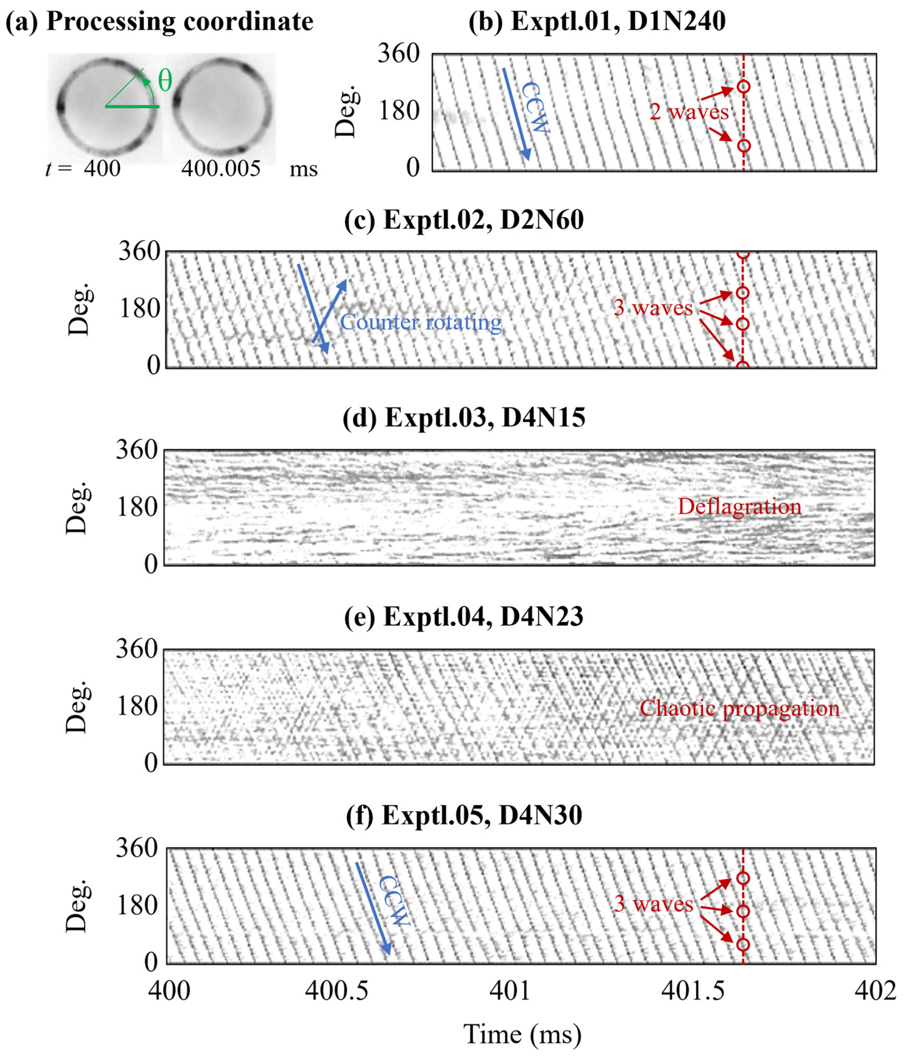
Image post-processing revealed that excessive jet penetration height negatively impacted both the initiation and sustainment of detonation. Notably, D4N15, which exhibited the highest jet penetration height, maintained a deflagration mode, while D4N23, with the second-highest penetration height, demonstrated a chaotic propagation mode.
(2)
STFT and FFT analyses were conducted on three injectors where detonation mode was sustained. Despite having narrower hole spacing and the capability for effective jet penetration height, D2N60 exhibited relatively unstable propagation characteristics compared to D4N30. This instability is likely attributed to the narrow spacing between the holes or its relatively high jet penetration height, which was the third highest among the injectors tested.
(3)
Each fuel injector was schematized based on design parameters, including hole spacing and jet penetration height. Despite D1N240 having low jet penetration height and a narrow gap between holes, its specific impulse was approximately 12% lower than that of D4N30. This result is likely attributable to insufficient jet penetration height. Therefore, it is essential to consider the optimization of design parameters to achieve an efficient injector performance.

Author Contributions

Conceptualization, J.-Y.C.; methodology, I.-H.K., G.-U.M., K.-H.L., S.-W.C. and J.-Y.C.; software, I.-H.K. and G.-U.M.; investigation, G.-U.M., I.-H.K., K.-H.L., S.-W.C. and J.-Y.C.; writing—original draft preparation, G.-U.M. and I.-H.K.; writing—review and editing, J.-Y.C.; visualization, G.-U.M. and I.-H.K.; supervision, J.-Y.C.; project administration, J.-Y.C.; funding acquisition, J.-Y.C. All authors have read and agreed to the published version of the manuscript.

Funding

This work was supported by the National Research Foundation of Korea (NRF) funded by the Ministry of Science and ICT (MSIT) under Grant Nos. 2022M1A3C2076724 and RS-2024-00359609).

Data Availability Statement

Data is contained within the article.

Conflicts of Interest

The authors declare no conflicts of interest.

References

  1. Kailasanath, K. Review of Propulsive applications of Detonation Waves. AIAA J. 2000, 38, 1698–1708. [Google Scholar] [CrossRef]
  2. Kailasanath, K. Recent Developments in the Research on Pulse Detonation Engines. AIAA J. 2003, 41, 145–159. [Google Scholar] [CrossRef]
  3. Wolański, P. Detonative Propulsion. Proc. Combust. Inst. 2013, 34, 125–158. [Google Scholar] [CrossRef]
  4. Li, J.M.; Teo, C.J.; Khoo, B.C.; Yao, S.; Wang, C. Detonation Control for Propulsion: Pulse Detonation and Rotating Detonation Engines; Shock Wave and High Pressure Phenomena; Springer: Berlin/Heidelberg, Germany, 2018. [Google Scholar]
  5. Lu, F.K.; Braun, E.M. Rotating Detonation Wave Propulsion: Experimental Challenges, Modeling, and Engine Concepts. J. Propuls. Power 2014, 30, 1125–1142. [Google Scholar] [CrossRef]
  6. Kim, J.M.; Niyasdeen, M.; Han, H.S.; Oh, S.; Choi, J.Y. Research Activities on PGC Propulsion based on RDE, Part I: Basic Studies. J. Korean Soc. Propuls. Eng. 2017, 21, 97–107. [Google Scholar] [CrossRef]
  7. Kim, J.M.; Niyasdeen, M.; Han, H.S.; Oh, S.; Choi, J.Y. Research Activities on PGC Propulsion Based on RDE, Part II: Application Studies. J. Korean Soc. Propuls. Eng. 2017, 21, 91–102. [Google Scholar] [CrossRef]
  8. Choi, J.Y.; Ma, F.H.; Yang, V. Some Numerical Issues on Simulation of Detonation Cell Structure. Combust. Explos. Shock Waves 2008, 44, 560–578. [Google Scholar] [CrossRef]
  9. Hishida, M.; Fujiwara, T.; Wolański, P. Fundamentals of Rotating Detonations. Shock Waves 2009, 19, 1–10. [Google Scholar] [CrossRef]
  10. Choi, J.Y.; Ma, F.; Yang, V. Numerical Simulation of Cellular Structure of Two-Dimensional Detonation Waves. In Proceedings of the 43rd AIAA Aerospace Science Meeting and Exhibit, Reno, Nevada, 10–13 January 2005; American Institute of Aeronautics and Astronautics, Inc.: Reston, VA, USA, 2005; p. 1174. [Google Scholar]
  11. Pavalavanni, P.K.; Kim, J.E.; Jo, M.S.; Choi, J.Y. Numerical Investigation of the Detonation Cell Bifurcation with Decomposition Technique. Aerospace 2023, 10, 318. [Google Scholar] [CrossRef]
  12. Cho, D.R.; Won, S.H.; Shin, J.R.; Choi, J.Y. Numerical Study of Three-Dimensional Detonation Wave Dynamics in a Circular Tube. Proc. Combust. Inst. 2013, 34, 1929–1937. [Google Scholar] [CrossRef]
  13. Rosato, D.A.; Thornton, M.; Sosa, J.; Bachman, C.; Goodwin, G.B.; Ahmed, K.A. Stabilized Detonation for Hypersonic Propulsion. Proc. Natl. Acad. Sci. USA 2021, 118, e2102244118. [Google Scholar] [CrossRef] [PubMed]
  14. Ishihara, K.; Nishimura, J.; Goto, K.; Nakagami, S.; Matsuoka, K.; Kasahara, J.; Matsuo, A.; Funaki, I.; Moriai, H.; Mukae, H.; et al. Study on a long-time Operation towards Rotating Detonation Rocket Engine Flight Demonstration. In Proceedings of the 55th AIAA Aerospace Sciences Meeting, Grapevine, TX, USA, 9–13 January 2017; p. 1062. [Google Scholar]
  15. Zonglin, J.; Zijian, Z.; Yunfeng, L.; Chun, W.; Changtong, L. Criteria for Hypersonic Air-Breathing Propulsion and its Experimental Verification. Chin. J. Aeronaut. 2021, 34, 94–104. [Google Scholar]
  16. Yamaguchi, M.; Matsuoka, K.; Kawasaki, A.; Kasahara, J.; Watanabe, H.; Matsuo, A. Supersonic Combustion Induced by Reflective Shuttling Shock Wave in Fan-Shaped Two-Dimensional Combustor. Proc. Combust. Inst. 2019, 37, 3741–3747. [Google Scholar] [CrossRef]
  17. Ma, F.; Choi, J.Y.; Yang, V. Thrust Chamber Dynamics and Propulsive Performance of Single-Tube Pulse Detonation Engines. J. Propuls. Power 2005, 21, 512–526. [Google Scholar] [CrossRef]
  18. Ma, F.; Choi, J.Y.; Yang, V. Thrust Chamber Dynamics and Propulsive Performance of Multitube Pulse Detonation Engines. J. Propuls. Power 2005, 21, 681–691. [Google Scholar] [CrossRef]
  19. Kim, J.M.; Han, H.S.; Choi, J.Y. The Experimental Study about the Effect of Operating Conditions on Multi-Tube Pulse Detonation Engine Performance. Int. J. Aeronaut. Space Sci. 2018, 19, 89–99. [Google Scholar] [CrossRef]
  20. Ma, F.; Choi, J.Y.; Yang, V. Propulsive Performance of Airbreathing Pulse Detonation Engines. J. Propuls. Power 2006, 22, 1188–1203. [Google Scholar] [CrossRef]
  21. Ma, F.; Choi, J.Y.; Yang, V. Internal Flow Dynamics in a Valveless Airbreathing Pulse Detonation Engine. J. Propuls. Power 2008, 24, 479–490. [Google Scholar] [CrossRef]
  22. Yi, T.H.; Lou, J.; Turangan, C.; Choi, J.Y.; Wolański, P. Propulsive Performance of a Continuously Rotating Detonation Engine. J. Propuls. Power 2011, 27, 171–181. [Google Scholar] [CrossRef]
  23. Jones, S.M.; Paxcon, D.E. Potential Benefits to Commercial Propulsion Systems from Pressure Gain Combustion. In Proceedings of the 49th AIAA/ASME/SAE/ASEE Joint Propulsion Conference, San Jose, CA, USA, 14–17 July 2013; American Institute of Aeronautics and Astronautics, Inc.: Reston, VA, USA, 2013; p. 3623. [Google Scholar]
  24. Frolov, S.M.; Dubrovskii, A.V.; Ivanov, V.S. Three-Dimensional Numerical Simulation of Operation Process in Rotating Detonation Engine. Prog. Propuls. Phys. 2013, 4, 467–488. [Google Scholar]
  25. Sousa, J.; Paniagua, G.; Morata, E.C. Thermodynamic Analysis of a Gas Turbine Engine with a Rotating Detonation Combustor. Appl. Energy 2017, 195, 247–256. [Google Scholar] [CrossRef]
  26. Strakey, P.; Ferguson, D.; Sisler, A.; Nix, A. Computationally Quantifying Loss Mechanisms in a Rotating Detonation Engine. In Proceedings of the 54th AIAA Aerospace Sciences Meeting, San Diego, CA, USA, 4–8 January 2016. [Google Scholar]
  27. Wolański, P. Application of the Continuous Rotating Detonation to gas Turbine. Appl. Mech. Mater. 2015, 782, 3–12. [Google Scholar] [CrossRef]
  28. Frolov, S.M.; Aksenov, V.S.; Ivanov, V.S. Experimental Proof of Zel’dovich Cycle Efficiency Gain over Cycle with Constant Pressure Combustion for Hydrogen—Oxygen Fuel Mixture. Int. J. Hydrogen Energy 2015, 40, 6970–6975. [Google Scholar] [CrossRef]
  29. Teasley, T.W.; Fedotowsky, T.M.; Gradl, P.R.; Austin, B.L.; Heister, S.D. Current State of NASA Continuously Rotating Detonation Cycle Engine Development. In Proceedings of the AIAA SciTech 2023 Forum, National Harbor, MD, USA, 23–27 January 2023. [Google Scholar]
  30. Goto, K.; Matsuoka, K.; Matsuyama, K.; Kawasaki, A.; Watanabe, H.; Itouyama, N.; Ishihara, K.; Buyakofu, V.; Noda, T.; Kasahara, J.; et al. Space Flight Demonstration of Rotating Detonation Engine Using Sounding Rocket S-520-31. J. Spacecr. Rocket. 2023, 60, 273–285. [Google Scholar] [CrossRef]
  31. Kawalec, M.; Wolański, P.; Perkowski, W.; Bilar, A. Development of a Liquid-Propellant Rocket Powered by a Rotating Detonation Engine. J. Propuls. Power 2023, 39, 554–561. [Google Scholar] [CrossRef]
  32. Ishihara, K.; Yoneyama, K.; Watanabe, H.; Itouyama, N.; Kawasaki, A.; Matsuoka, K.; Kasahara, J.; Matsuo, A.; Funaki, I.; Higashino, K. Thrust Performance of Converging Rotating Detonation Engine Compared with Steady Rocket Engine. J. Propuls. Power 2023, 39, 297–307. [Google Scholar] [CrossRef]
  33. Bach, E.; Paschereit, C.O.; Stathopoulos, P.; Bohon, M. Advancement of Empirical Model for Stagnation Pressure Gain in RDCs. In Proceedings of the AIAA SciTech 2022 Forum, San Diego, CA, USA, 3–7 January 2022. [Google Scholar]
  34. Liu, X.Y.; Luan, M.Y.; Chen, Y.L.; Wang, J.P. Flow-Field Analysis and Pressure Gain Estimation of a Rotating Detonation Engine with Banded Distribution of Reactants. Int. J. Hydrogen Energy 2020, 45, 19976–19988. [Google Scholar] [CrossRef]
  35. Goto, K.; Yokoo, R.; Kawasaki, A.; Matsuoka, A.; Kasahara, J.; Matsuo, A.; Funaki, I.; Kawashima, H. Investigation into the Effective Injector Area of a Rotating Detonation Engine with Impact of Backflow. Shock Waves 2021, 31, 753–762. [Google Scholar] [CrossRef]
  36. Plaehn, E.W.; Walters, I.V.; Gejji, R.M.; Slabaugh, C.D. Bifurcation in Rotating Detonation Engine Operation with Continuously Variable Fuel Injection Location. J. Propuls. Power 2023, 39, 202–216. [Google Scholar] [CrossRef]
  37. Koo, I.H.; Lee, K.H.; Kim, M.S.; Han, H.S.; Kim, H.; Choi, J.Y. Effects of Injector Configuration on the Detonation Characteristics and Propulsion Performance of Rotating Detonation Engine (RDE). Aerospace 2023, 10, 949. [Google Scholar] [CrossRef]
  38. Matsuoka, K.; Tanaka, M.; Noda, T.; Kawasaki, A.; Kasahara, J. Experimental Investigation on a Rotating Detonation Cycle with Burned Gas Backflow. Combust. Flame 2021, 225, 13–19. [Google Scholar] [CrossRef]
  39. Bennewitz, J.W.; Bigler, B.R.; Pilgram, J.J.; Hargus, W.A., Jr. Modal Transitions in Rotating Detonation Rocket Engines. Int. J. Energetic Mater. Chem. Propuls. 2019, 18, 91–109. [Google Scholar] [CrossRef]
  40. Rankin, B.A.; Richardson, D.R.; Caswell, A.W.; Naples, A.G.; Hoke, J.L.; Schauer, F.R. Chemiluminescence Imaging of an Optically Accessible Non-Premixed Rotating Detonation Engine. Combust. Flame 2017, 176, 12–22. [Google Scholar] [CrossRef]
  41. Duvall, J.; Chacon, F.; Harvey, C.; Gamba, M. Study of the Effects of Various Injection Geometries on the Operation of a Rotating Detonation Engine. In Proceedings of the 2018 AIAA Aerospace Sciences Meeting, Kissimmee, FL, USA, 8–12 January 2018. [Google Scholar]
  42. Bohon, M.D.; Bluemner, R.; Paschereit, C.O.; Gutmark, E.J. High-Speed Imaging of Wave Modes in an RDC. Exp. Therm. Fluid Sci. 2019, 102, 28–37. [Google Scholar] [CrossRef]
  43. Zhao, M.; Zhang, H. Origin and Chaotic Propagation of Multiple Rotating Detonation Waves in Hydrogen/Air Mixtures. Fuel 2020, 275, 117986. [Google Scholar] [CrossRef]
  44. Bigler, B.R.; Burr, J.R.; Bennewitz, J.W.; Danczyk, S.; Hargus, W.A. Performance Effects of Mode Transitions in a Rotating Detonation Rocket Engine. In Proceedings of the AIAA Propulsion and Energy 2020 Forum, Online, 24–28 August 2020. [Google Scholar]
  45. Lee, J.H.; Ryu, J.H.; Lee, E.S.; Han, H.S.; Choi, J.Y. Experimental Proof of Concept of a Noncircular Rotating Detonation Engine (RDE) for Propulsion Applications. Aerospace 2022, 10, 27. [Google Scholar] [CrossRef]
  46. Han, H.S.; Lee, E.S.; Choi, J.Y. Experimental Investigation of Detonation Propagation Modes and Thrust Performance in a Small Rotating Detonation Engines Using C2H4/O2 Propellant. Energies 2021, 14, 1381. [Google Scholar] [CrossRef]
  47. Lin, W.; Zhou, J.; Liu, S.; Lin, Z.; Zhuang, F. Experimental Study on Propagation Mode of H2/Air Continuously Rotating Detonation Wave. Int. J. Hydrogen Energy 2015, 40, 1980–1993. [Google Scholar] [CrossRef]
  48. Jia, B.; Zhang, Y.; Meng, H.; Meng, F.; Pan, H.; Hong, Y. Experimental Study on the Propagation Characteristics of Rotating Detonation Wave with Liquid Hydrocarbon/High-Enthalpy Air Mixture. Aerospace 2023, 10, 682. [Google Scholar] [CrossRef]
  49. Ding, C.; Wu, Y.; Xu, G.; Xia, Y.; Li, Q.; Weng, C. Effects of the Oxygen Mass Fraction on the Wave Propagation Modes in a Kerosene-Fueled Rotating Detonation Combustor. Acta Astronaut. 2022, 195, 204–214. [Google Scholar] [CrossRef]
  50. Bluemner, R.; Bohon, M.D.; Paschereit, C.O.; Gutmark, E.J. Counter-Rotating Wave Mode Transition Dynamics in an RDC. Int. J. Hydrogen Energy 2019, 44, 7628–7641. [Google Scholar] [CrossRef]
  51. Lee, S.H.; Cho, D.R.; Choi, J.Y. Effect of Curvature on the Detonation Wave Propagation Characteristics in Annular Channel. In Proceedings of the 46th AIAA Aerospace Sciences Meeting and Exhibit, Reno, Nevada, 7–10 January 2008; American Institute of Aeronautics and Astronautics, Inc.: Reston, VA, USA, 2008; p. 988. [Google Scholar]
  52. Kim, T.Y.; Choi, J.Y. Numerical Study of Detonation Wave Propagation in 2-D Channels of Arbitrary Radius of Curvature. AIAA J. 2014, 20, 14–3903. [Google Scholar]
  53. Niyasdeen, M.; Oh, S.; Kim, K.S.; Choi, J.Y. Quasi-steady State Simulation of Rotating Detonation Engine. Int. J. Aeronaut. Space Sci. 2015, 16, 548–559. [Google Scholar] [CrossRef]
  54. Nejaamtheen, M.N.; Kim, T.Y.; Pavalavanni, P.K.; Ryu, J.; Choi, J.Y. Effects of the Dimensionless Radius of an Annulus on the Detonation Propagation Characteristics in Circular and Non-Circular Rotating Detonation Engines. Shock Waves 2021, 31, 703–715. [Google Scholar] [CrossRef]
  55. Kim, K.M.; Baek, S.W.; Kim, Y.G. Effects of Aspect Ratio of a Fuel Injection Nozzle into a Supersonic Air Stream on Combustion Characteristics. J. Korean Soc. Propuls. Eng. 2004, 8, 44–53. [Google Scholar]
  56. Gruber, M.R.; Nejad, A.S.; Chen, T.H.; Dutton, J.C. Mixing and Penetration Studies of Sonic Jets in a Mach 2 Freestream. J. Propuls. Power 1995, 11, 315–323. [Google Scholar] [CrossRef]
  57. Brunner, E. Fluid Mixtures at High Pressures II: Phase Separation and Critical Phenomena of (ethane + an n-alkanol) and of (ethane + methanol) and (propane + methanol). J. Chem. Thermodyn. 1985, 17, 871. [Google Scholar] [CrossRef]
  58. Jahangiri, M. A Thermodynamics Property Formulation for Ethylene from the Freezing Line to 450 K at Pressure to 260 MPa. Ph.D. Thesis, Unviersity of Idaho, Moscow, ID, USA, 1984. [Google Scholar]
  59. Tsonopoulous, C.; Ambrose, D. Vapor-Liquid Critical Properties of Elements and Compounds. 6. Unsaturated Aliphatic Hydrocarbons. J. Chem. Eng. 1996, 41, 645–656. [Google Scholar]
Figure 1. Schematics of experimental RDE model: (a) Schematic of annular RDE and instrumentation installation. (b) Schematic of propellant injection structure.
Aerospace 11 00752 g001
Figure 2. Schematic of the pre-detonator installed tangentially to the RDE combustion channel.
Aerospace 11 00752 g002
Figure 3. Five manufactured fuel injectors (part of center-body in RDE).
Aerospace 11 00752 g003
Figure 4. Theoretical mass flow rate and experimental mass flow rate reflecting production error: (a) Mass flow rate of oxidizer and D4 fuel injectors. (b) D1N24 and D2N60 fuel injectors’ mass flow rate.
Aerospace 11 00752 g004
Figure 5. Calculated jet penetration heights for the five manufactured injectors.
Aerospace 11 00752 g005
Figure 6. Load cell calibration result.
Aerospace 11 00752 g006
Figure 7. Experimental sequence of the RDE hot fire test: time sequence of each valve and ignition.
Aerospace 11 00752 g007
Figure 8. Comparison of thrust and specific impulse results: (a) m ˙ = 107 g/s with Φ = 1.01, (b) m ˙ = 160 ± 0.9 g/s with Φ = 0.471 ± 0.005, and (c) various conditions.
Aerospace 11 00752 g008
Figure 9. The history of thrust and pressure: (a) Exptl.03, D4N15 without back-pressure and (b) Exptl.05, D4N30 with back-pressure.
Aerospace 11 00752 g009
Figure 10. High-speed-camera pictures and image-processing images for combustion-mode verification: (a) high-speed-camera snapshots and image-processing coordinate; (b) 2-wave detonation of Exptl.01, D1N240; (c) 3-wave detonation with counter-rotating of Exptl.02, D2N60; (d) deflagration with D4N15 of Exptl.03; (e) Exptl.04, chaotic propagation with D4N23 fuel injector; and (f) 3 detonation waves with D4N30 of Exptl.05.
Aerospace 11 00752 g010
Figure 11. Detonation propagation analysis based on STFT and FFT results: (a) wave mode with D1N240 of Exptl.01, (b) relatively unstable propagation with D2N60, and (c) 3-wave mode with D4N30 of Exptl.06.
Aerospace 11 00752 g011
Figure 12. Wall pressure of D4 fuel injectors.
Aerospace 11 00752 g012
Figure 13. Combustion mode and specific impulse according to injector parameters.
Aerospace 11 00752 g013
Table 1. Ideal and actual specification of fuel injector.
InjectorNholeIdeal DesignActual DesignMaterials
Dhole (mm)Af,inj (mm2)Dhole (mm)Af,inj (mm2)
D1N2402400.2511.780.3017.22SUS316
D2N60600.5011.780.5815.72SUS316
D4N15151.011.781.1716.20SUS316
D4N23231.018.061.0319.31C1100
D4N30301.023.551.0023.63C1100
Table 2. (a) Critical pressures of ethylene (C2H4). (b) Critical temperatures of ethylene (C2H4).
(a)
Pc (bar)ReferenceComment
50.55 1Brunner [57]Uncertainty assigned by TRC = 0.0504 bar
50.403 1Jahangiri [58]Uncertainty assigned by TRC = 0.002 bar
50.41 ± 0.04 1Tsonopoulos and Ambrose [59]-
(b)
T (K)ReferenceComment
282.33 1Brunner [57]Uncertainty assigned by TRC = 0.0504 K
282.34 1Jahangiri [58]Uncertainty assigned by TRC = 0.002 K
282.3 ± 0.02 1Tsonopoulos and Ambrose [59]-
1 National Institute of Standard and Technology (NIST) Chemistry WebBook.
Table 3. Summary of experiment results.
ExperimentInjector m ˙   (g/s) Φ Combustion ModefDW (kHz)Isp (s)
Exptl.01D1N2401030.98Detonation19.7365.98
Exptl.02D2N601071.09Detonation22.5067.97
Exptl.03D4N151091.14Deflagration-73.94
Exptl.04D4N231051.11Chaotic Propagation22.5078.25
Exptl.05D4N301071.01Detonation21.2175.47
Disclaimer/Publisher’s Note: The statements, opinions and data contained in all publications are solely those of the individual author(s) and contributor(s) and not of MDPI and/or the editor(s). MDPI and/or the editor(s) disclaim responsibility for any injury to people or property resulting from any ideas, methods, instructions or products referred to in the content.

