Article

Numerical Investigation on the Thermal Characteristics of Lightweight Metal Mesh-Based Reflector Antenna with Various Knitting Conditions

1
Department of Aerospace and Mechanical Engineering, Korea Aerospace University, 76 Deokyang-gu, Goyang-si 10540, Republic of Korea
2
STEP Lab. Ltd., 236-3, Bogyongdong-ro, Yuseong-gu, Daejeon 34202, Republic of Korea
*
Author to whom correspondence should be addressed.
Aerospace 2024, 11(9), 780; https://doi.org/10.3390/aerospace11090780
Submission received: 2 July 2024 / Revised: 10 September 2024 / Accepted: 19 September 2024 / Published: 20 September 2024
(This article belongs to the Section Astronautics & Space Science)

Abstract

:
Proper prediction of the temperature variation in a metallic wire mesh for spaceborne large deployable reflector antennas is essential for evaluating the dimensional stability of the antenna under extreme on-orbit thermal environments. However, predicting the temperature of a mesh is difficult because of its complex yarn configuration. To analyze the thermal behavior of the spaceborne mesh antenna reflector, the thermal optical characteristics with various knitting methods of the metallic mesh were obtained experimentally in this study. Subsequently, to analyze the thermal sensitivity of the reflector based on its optical properties, an on-orbit thermal analysis of the mesh reflector was performed based on measurements of the mesh specimen. We also investigated the influence of deployable solar panels on the thermal gradient of the reflector.

1. Introduction

Recently, the demand for satellite missions has grown and become more complex, driven by advancements in communication, Earth observation, and scientific research. Consequently, research on the development of high-gain antennas has become increasingly critical, and the applications of large-scale antennas have expanded significantly [1,2,3]. In recent decades, several antenna-reflector design concepts have been proposed. Among these, the mesh antenna reflector is regarded as one of the most suitable types for large deployable antennas owing to its light weight, high accuracy, and small packed volume [4,5,6].
With the increasing demand for mesh antenna reflectors, the mechanical properties of mesh fabrics have received increasing attention. The most commonly applied fabrics for antennas are warp knits, and the warp knitting parameters are crucial in determining the knitting process as well as the electrical and mechanical properties of the mesh fabric [7]. Among these parameters, opening per inch (OPI) is used to measure the weave density of the mesh fabric, and refers to the number of holes per inch. Normally, OPI is increased to reduce loss as the mission operating frequency band of the antenna increases [8].
The optical properties of the mesh reflector include transmittance, which is determined by the pore characteristics of the mesh fabric. Transmittance quantifies the ability of a mesh fabric surface to transmit light and is proportional to the pore size per unit area of the mesh fabric. Although opening per inch (OPI) is the main factor in determining pore size, other parameters such as yarn diameter, pattern, and the number of ply yarns can also alter pore dimensions, even at the same OPI. Consequently, the optical properties of the mesh, including transmittance, absorptance, and reflectance, vary accordingly. These optical properties are critical in determining the thermal behavior and temperature gradients of the antenna when exposed to extreme space thermal environments. Significant temperature gradients on the reflector can cause thermal deformation, leading to surface contour errors that degrade radio frequency (RF) performance and antenna pointing accuracy [9,10,11]. Therefore, predicting the thermal characteristics of the reflector in an orbital environment requires a thorough analysis of the optical properties influenced by mesh fabric parameters. Additionally, it is essential to investigate in advance how these optical properties affect the thermal behavior of the mesh reflector in the orbital thermal environment.
Various studies have described the importance of investigating the optical properties to analyze the thermal behavior of mesh antennas. The fact that these optical properties can serve as factors needed to solve thermal design problems for maintaining the surface accuracy of mesh antenna reflectors has been demonstrated. Denisova et al. [12] proposed favorable material properties for large deployable mesh antennas by measuring the optical properties according to the wire material and coating methods, comparing the absorption rates of different materials based on the presence of gold plating, and analyzing the rate of change in the material properties with wavelength. Mironov et al. [13] described a method for measuring the optical properties of a mesh woven with a nichrome wire to ensure the thermal reliability of a mesh antenna reflector in an on-orbit thermal environment.
However, previous studies have not investigated the thermal properties of the mesh antenna reflector surface through an on-orbit thermal analysis based on the measured optical properties of the mesh. Furthermore, variations in the optical properties depending on various design factors of the mesh and the thermal effects between the mesh and the antenna reflectors have not been examined. While the mesh fabrication process involves iterative adjustments and comparative analysis of samples post-production, the absence of a comprehensive database for satellite mesh fabrics often results in prolonged development cycles and increased production costs due to the lack of clear criteria for process optimization. Therefore, further theoretical analysis and design optimization research are essential to supplement the fundamental data required for efficient design.
In this study, as shown in Figure 1, optical properties were measured using five mesh specimens with different combinations of knitting parameters (OPI, knitting pattern, and number of twists), tailored to meet the electrical and mechanical requirements of the antenna. Additionally, to investigate the variation in transmittance based on the initial tension and direction between the mesh and antenna rib structure, three specimens with different tension directions were analyzed. Based on the measurement results, a thermal model of the mesh reflector was constructed, and an on-orbit thermal analysis was performed to analyze the thermal characteristics and sensitivity of the reflector depending on the mesh parameters when the reflector was exposed to on-orbit thermal environments. Furthermore, we investigated the influence of the deployed solar panels, which is a factor affecting the thermal distortion of the reflector.

2. Overview of Spaceborne Metal Mesh Fabric

When designing mesh reflectors for antennas, satisfying requirements such as mechanical, microwave electrical, foldability, wrinkle resistance, and light transmittance is essential [14]. Typical materials used in mesh reflectors include nickel-plated stainless steel, molybdenum, and tungsten, which offer high strengths and low thermal expansion coefficients [15,16]. Additionally, the metal wires were gold plated to provide excellent corrosion resistance and high electrical conductivity. The mesh fabric for the satellite antennas was woven using methods similar to the traditional textile manufacturing techniques. Typical woven methods include weaving, warping, and non-woven techniques. Braided warp knitting is preferred for antenna meshes owing to its superior durability and elasticity. The patterns used were Tricot, Atlas, and SATIN [17]. The mesh fabric has a porous structure defined by the OPI, indicating its density. Additionally, OPI is linearly related to the mission frequency band. The amount of wire and knitting process used to produce the mesh depend on the wire material, pattern, and OPI, which determine the RF performance of the mesh. Knitting processes are complex and time consuming [7]. Therefore, pre-evaluating the characteristics of each mesh factor to ensure that the mesh fabric satisfies the antenna requirements while minimizing the manufacturing duration is necessary.
As previously mentioned, mesh reflectors are designed to be thin and lightweight. In on-orbit thermal environments, the antenna is exposed to extremely low temperatures (below 100 K) during the eclipse period and excessive heat during the sunlight period. Moreover, temperature gradients can cause thermal deformation and reduce RF performance. To maintain surface accuracy in an on-orbit thermal environment, predicting thermal stability is essential. To predict the thermal behavior of an antenna, the optical properties of the mesh constituting the reflector must be investigated. The optical properties of the mesh have transmission characteristics that differ from those of solid antenna reflectors. The transmission characteristics change mainly with the OPI of the mesh, which is influenced by factors such as the mission frequency band, knitting pattern, number of twists, and initial tensile force that occur when the mesh is fastened to the rim structure. Consequently, it is essential to analyze the thermal behavior of the mesh antenna reflector by considering the changes in transmission characteristics depending on the factor of the mesh fabric.

3. Optical Properties Measurement

3.1. Description of the Mesh Specimen

Table 1 shows five different mesh specimens for optical property measurements, classified by knitting pattern, OPI, and number of yarn ply. The knitting patterns include Atlas, Atlas-Atlas, Double-Atlas, and TUCH. Specifically, the knitting pattern for Case 3 is Double-Atlas, which refers to a fabric where either or both of the warp and weft threads overlap in two layers, unlike typical fabrics that consist of a single layer. Consequently, Double-Atlas exhibits greater durability than the Atlas pattern. Except for Case 5, all specimens are composed of a single yarn type. The OPI values of the specimens were set at 10, 12, 18, and 36.
To assess the sensitivity of optical properties to initial tension and the changes in OPI due to tension direction, a special jig was designed. This jig enables measurements under tension. The specimens were prepared as detailed in Table 2. Using specimen 5 (12 OPI) from Table 1, the mesh was fixed to the jig with appropriate tension applied in the Wale, Course, and Wale and Course directions.

3.2. Results of Measurement

Figure 2 shows the spectrophotometer (Cary 5000, Agilent Technologies, Santa Clara, CA, USA) used to measure the optical properties of the specimens in this study. Spectrophotometers use a light source to illuminate a sample with light in the Ultraviolet (UV) to near-infrared (NIR) wavelength range. The instruments measure the light absorbed, transmitted, or reflected by the sample at each wavelength [18].
In this study, the spectral measurement range of the instrument was 300–2500 nm, and a Cary 5000 two-channel spectrophotometer was equipped with an integrating sphere accessory known as the sample holder compartment, which is available for specular reflection measurements [19].
Figure 3 shows representative results (Specimen 5) of the optical property spectrum of the measured mesh fabric. For all the specimens, including Specimen 5, the transmittance was measured to be over 80%, which was confirmed to be owing to the characteristics of the mesh in which pores were formed. Additionally, the absorptivity remained below 0.1 over the entire spectral range, and the reflectance did not exceed 0.15. The optical properties of all specimens are quantified in Table 3 by calculating the average values at 5 nm intervals over the measured wavelength range, and the graph is shown in Figure 4. The absorptivity was calculated using the following equation:
R + T + A = 1 ,
where R is reflectance, T is transmittance, and A is absorptivity.
From the measurements on Specimens 1–5, we confirmed that the transmittance generally decreased as the OPI increased when the specimen was in a standard state. However, there was no absolute inverse relationship between the OPI and transmissivity, and the two cases described later can be confirmed by comparing the results of the optical characterization of each specimen performed in this study. First, the transmittance of Specimen 3 (18 OPI) is 0.84, which is approximately 0.04 lower than that of Specimen 1 (36 OPI), despite having a lower OPI. This indicates that Specimen 3, characterized by a double-weave structure, had a higher density than regular fabrics, resulting in reduced light transmittance. Second, the transmittance of Specimen 5 (12 OPI) was 0.81, which was lower than those of Specimens 1, 2 (36 OPI), and 3 (18 OPI), which had higher OPI. This indicates that Specimen 5 was the only specimen composed of 3 ply wires, and the transmittance decreased as the reflected area increased compared with a single wire. Additionally, when comparing Specimens 1 (Atlas) and 2 (TUCH), which differed only in the mesh-knitting pattern, the transmittance of the Atlas pattern was measured to be 0.05 higher than that of TUCH. This was analyzed as a difference owing to the size and regularity of the pores comprising the pattern. Moreover, the Atlas pattern exhibiting a broader lattice structure, which enhanced the transmittance, was verified.
Additionally, as a result of the analysis according to the stretching direction, the OPI of Specimens 5–3, which was multiaxially stretched rather than uniaxially stretched, decreased by about 2 OPI compared to Specimen 5 (standard state), and the transmittance of the mesh increased. Figure 4 effectively illustrates the proportion of transmittance in the optical properties of the mesh fabric. Consequently, these results indicate that the optical properties of the mesh are not only influenced by the OPI, but also by the various design variables that constitute the mesh. These design variables also affect the thermal characterization of the mesh reflector; therefore, it is important to consider them during the design process.

4. On-Orbit Thermal Analysis

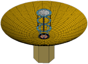
4.1. Description of the Thermal Model and On-Orbit Conditions

Figure 5 shows the antenna thermal mathematical model (TMM)that was constructed using Thermal Desktop [20], a CAD-based geometric interface for commercial on-orbit thermal analysis tools of systems integrated differencing numerical analyzer/fluid integrator (SINDA/FLUINT) [21]. The antenna consists of a mesh-type primary reflector, secondary reflector, solar panels, and spacecraft (S/C). To investigate the thermal behavior and temperature gradient of the antenna surface owing to the transmittance characteristics of the reflector, the rim support structure of the reflector was excluded. For the same reason, the S/C was covered with multilayer insulation (MLI) to insulate its surface from the external heat exchange. To simplify the thermal analysis model of the solar panels, the optical properties of the solar cells were applied on the front side, and white paint was applied on the rear side. Table 4 summarizes the thermo-physical and optical properties that were used during thermal analysis. To analyze the thermal behavior of the reflector under various transmittance characteristics in orbit, eight thermal design cases, based on the previously measured results of the mesh specimens, are listed in Table 5. These cases shown in Table 5 are based on the previously measured results of the mesh specimens. And, the physical properties were based on the thermal–physical property variation curves of gold-plated molybdenum, as analyzed by Guo et al. [22]. Identical physical properties were applied to all the analysis conditions to exclude the influence of material differences. Additionally, the allowable temperature limits for the antenna components were not defined because the objective was to identify a feasible thermal design by comparing the thermal gradients of the reflector in this study.
For the analysis, the orbital parameters and thermal conditions for the worst hot and cold conditions were assumed to evaluate the temperature conditions of the reflector, as listed in Table 6. The orbit assumed in this study is circular, with an altitude of 550 km and an orbital inclination angle of 45°. The worst hot and cold conditions correspond to the cases when the reflector is operated during the winter solstice with the highest incoming heat flux and the summer solstice with the lowest incoming heat flux, respectively. Figure 6a,b shows examples of orbital profiles of the antenna under the worst hot and cold conditions. During periods of non-imaging, the solar panels maintain the sun pointing, and the front radiating side of the antenna is installed on the opposite side of the S/C, oriented toward the anti-sun direction. During the eclipse period, the S/C adjusts the attitude toward the nadir pointing of the antenna to prevent excessive heat loss into deep space. Additionally, we assumed that the antenna maintained Earth pointing at a specified incidence angle for 10 min to conduct image acquisition, lasting for 3.5 min, followed by data transmission to the ground station for 3.3 min before and after imaging.

4.2. Results of On-Orbit Thermal Analysis

As the first step in analyzing the thermal properties of the reflector, the temperature of the primary reflector was compared with and without transmissivity properties owing to the characteristics of the mesh fabric. For this purpose, the optical properties of the reflector were analyzed for Case 5, which resulted in minimum transmittance among the analyzed conditions shown in Figure 4, and for the experimentally measured optical properties of Gottero et al. [23], which are listed in Table 5, without considering transmittance. The analysis results confirmed the maximum ( T m a x ), minimum ( T m i n ), and average ( T a v g ) temperatures under the worst hot and cold conditions. The temperature gradient of the reflector was evaluated by estimating the temperature deviation between the maximum and minimum temperature values.
Figure 7 and Figure 8 show the temperature profiles with and without the transmittance, respectively. Moreover, representative temperature contours of the reflector during imaging, sunlight, and eclipse periods are shown in Figure 9 and Figure 10 to explain the temperature gradient ( T = T m a x T m i n ) of the reflector. In the worst hot condition, the largest T during the orbital period was observed for the reflector during imaging period. This is because the partial area of the reflector is shaded by the S/C body, whereas the remaining area is exposed to the illumination of the sun. In the worst cold condition, the largest T occurs after the antenna exits the eclipse period. Since the eclipse period is 30.8 minutes longer under worst cold case compared to worst hot condition, the antenna’s temperature remains lower. Consequently, when the antenna is exposed to the sunlight period, a significant temperature difference occurs. This trend in the temperature profile is similar to that of the other analysis conditions, which will be described later.
Figure 7 shows that the T m a x of the reflector without transmittance is 278.29 °C and T m i n is −59.09 °C, whereas Figure 8 shows that the T m a x of the reflector with transmittance is 90.46 °C and T m i n is −54.04 °C, which is relatively low. Additionally, the comparison of the maximum T shows that the temperature deviation is up to 176.07 °C without transmittance and 57.29 °C with transmittance, which is approximately 118.78 °C lower, indicating that the consideration of transmittance is essential to determine the reliable thermal behavior of the reflector.
Figure 11 shows a graph comparing the maximum T within a single orbit under various optical characteristic (Cases 1 to 5) under the worst cold and hot conditions. Among the five cases, Case 4 is the lowest maximum T , with values of 22.3 °C and 28.2 °C in the worst cold and hot conditions, respectively. Case 4 has a single-yarn Atlas knitting pattern and with the lowest OPI (10 OPI) among all case. Accordingly, the transmittance is the highest at 0.93. Conversely, Case 5 demonstrated the largest maximum T of 61.6 °C. Despite having an OPI (12 OPI) which is the second lowest among the specimens, it consists of three plies and has the lowest transmittance of 0.81. This is because transmissivity decreases as the area increases as it is composed of ply wires. Furthermore, a similar trend of decreasing temperature gradient with the increase in transmissivity was observed in Cases 1, 2, and 3.
Figure 12 shows the maximum T graph of Case 5 to 5-3 to show the influence of the temperature gradient according to the tensile direction of the mesh. The temperature gradient difference between the reflectors of Cases 5 and 5-3, where the transmissivity difference among the four cases is maximized at 0.05, is found to be relatively low at approximately 12.6 °C. This indicates that the difference in the 1–2 OPI resulting from tension suggests a low thermal sensitivity.
As previously mentioned, the metallic mesh is extremely thin and lightweight, making it particularly susceptible to thermal deformation. Therefore, it is crucial to analyze the factors that contribute to high temperature gradients in the mesh reflector while in orbit. In this study, we further examined the impact of shadows cast by large deployed structures, specifically the satellite’s solar panels. To assess the temperature gradients induced on the mesh reflector by these shadows, we conducted on-orbit thermal analysis under five different cases, each assuming a different solar panel configuration. The thermal design for the analysis was based on Case1 under the assumption of a hot case. Table 7 summarizes the thermal analysis results of T m a x , T m i n , and T for various configurations of the solar panels. The table indicates that the presence of the solar panels causes a shading effect on the partial area of the primary reflector throughout the sunlight period, which results in an increase in T in the primary reflector during the imaging period, as shown in Figure 13. The following results show the influence of the number and length of solar panels on T .
In the case of three and four solar panels with an area of 2.2 m × 5.5 m, T is approximately 8 °C and 12.6 °C higher than in the case without solar panels, respectively. The T generated by applying six solar panels with an area of 2.2 m × 3.5 m is 20.5 °C, which is 15.6 °C higher than the case without solar panels, showing the largest ∆T. However, the variation in temperature gradient with regard to area change is not significantly sensitive. The analysis shows that the T of the antenna reflector tends to increase with the number of solar panels, but the difference in temperature gradient is not significant. This is because of the characteristics of the mesh fabric with high transmittance, indicating that the influence of temperature gradient on the solar panel configuration is low. In summary, while T of the antenna reflector tends to increase with the number of solar panels, its impact is not significant. This is owing to the characteristics of the mesh fabric with high transmittance, indicating a low influence of the temperature gradient on the configuration of the solar panels.

5. Conclusions

In this study, we investigated how the design parameters resulting from the electrical/mechanical performance of knitted meshes for satellite antennas affect the optical properties that are directly related to the thermal behavior of the mesh. For this purpose, the optical properties of eight types of specimens with different knitting patterns, OPI, numbers of twists, and tensile directions were measured. From the measurement results, we experimentally demonstrated that the optical properties of the mesh did not depend on a single design parameter. Additionally, depending on the pore characteristics of the mesh, the transmittance was measured to be over 80% for all specimens. Thus, it was shown through orbital thermal analysis that the transmission characteristics must be reflected to increase the reliability of the mesh antenna reflector thermal model. Then, thermal behavior and sensitivity analyses of the reflector were performed through antenna thermal analysis using the optical properties of the specimen. Furthermore, the effect of the deployed solar panels on the thermal gradient of the reflector was investigated. The results indicated that reducing the solar panel length while increasing the number of panels is one way to minimize the increase in the thermal gradient.

Author Contributions

Conceptualization, M.-Y.S. and H.-U.O.; methodology, M.-Y.S., B.-G.C. and H.-U.O.; validation, B.-G.C. and H.-U.O.; formal analysis, M.-Y.S.; investigation, H.-M.S.; data curation, H.-M.S.; writing—original draft preparation, B.-G.C.; writing—review and editing, B.-G.C. and H.-U.O.; visualization, B.-G.C. and H.-U.O.; supervision, H.-U.O.; project administration, B.-G.C. and H.-U.O.; funding acquisition, H.-U.O. All authors have read and agreed to the published version of the manuscript.

Funding

This study was funded by the Institute of Civil-Military Technology Cooperation (ICMTC), Republic of Korea.

Data Availability Statement

The data presented in this study are available on request from the corresponding author.

Acknowledgments

This research was financially supported by the Instituted of Civil Military Technology Cooperation funded by the Defense Acquisition Program Administration and Ministry of Trade, Industry and Energy of Korean government under grant No. 22-CM-00-64.

Conflicts of Interest

Author Bong-Geon Chae was employed by the company STEP Lab. Ltd. The remaining authors declare that the research was conducted in the absence of any commercial or financial relationships that could be construed as a potential conflict of interest.

References

  1. Duan, B.; Zhang, Y.; Du, J. Large Deployable Satellite Antennas; Springer: Singapore, 2020. [Google Scholar]
  2. Akira, M.; Kyoji, S.; Motofumi, U.; Akio, T. In-Orbit Deployment Characteristics of Large Deployable Antenna Reflector Onboard Engineering Test Satellite VIII. Acta Astronaut. 2009, 65, 1306–1316. [Google Scholar]
  3. Scialino, L.; Ihle, A.; Migliorelli, M.; Gatti, N.; Datashvili, L.; van‘t Klooster, K.; Santiago Prowald, J. Large deployable reflectors for telecom and earth observation applications. CEAS Space J. 2013, 5, 125–146. [Google Scholar] [CrossRef]
  4. Im, C.; Seo, W.; Park, S.; Kim, K.; Park, S.; Choo, H. Design of a Deployable Broadband Mesh Reflector Antenna for a SIGINT Satellite System Considering Surface Shape Deformation. Sensors 2024, 24, 384. [Google Scholar] [CrossRef] [PubMed]
  5. Urata, K.N.; Sri Sumantyo, J.T.; Santosa, C.E.; Viscor, T. Development of an L-band SAR microsatellite antenna for earth observation. Aerospace 2018, 5, 128. [Google Scholar] [CrossRef]
  6. Li, P.; Liu, C.; Tian, Q.; Hu, H.; Song, Y. Dynamics of a deployable mesh reflector of satellite antenna: Parallel computation and deployment simulation. J. Comput. Nonlinear Dyn. 2016, 11, 061005. [Google Scholar] [CrossRef]
  7. Xu, H.; Chen, N.; Jiang, J. Research on the Knittability of Metallic Yarns in the Warp-knitted Mesh of a Deployable Antenna. Fibres Text. East. Eur. 2023, 31, 51–55. [Google Scholar]
  8. Chahat, N.; Hodges, R.E.; Sauder, J.; Thomson, M.; Rahmat-Samii, Y. The deep-space network telecommunication CubeSat antenna: Using the deployable Ka-band mesh reflector antenna. IEEE Antennas Propag. Mag. 2017, 59, 31–38. [Google Scholar] [CrossRef]
  9. Yang, G.; Tang, A.; Yuan, Z.; Yang, Z.; Li, S.; Li, Y. Surface shape stability design of mesh reflector antennas considering space thermal effects. IEEE Access 2020, 8, 89071–89083. [Google Scholar] [CrossRef]
  10. Nie, R.; He, B.; Yan, S.; Ma, X. Optimization design method for the cable network of mesh reflector antennas considering space thermal effects. Aerosp. Sci. Technol. 2019, 94, 105380. [Google Scholar] [CrossRef]
  11. Park, T.Y.; Kim, S.Y.; Yi, D.W.; Jung, H.Y.; Lee, J.E.; Yun, J.H.; Oh, H.U. Thermal design and analysis of unfurlable CFRP skin-based parabolic reflector for spaceborne SAR antenna. Int. J. Aeronaut. Space Sci. 2021, 22, 433–444. [Google Scholar] [CrossRef]
  12. Mironov, R.A.; Reznik, S.V.; Rukavishnikov, R.V.; Shishulina, V.A.; Zavaruev, V.A. Optical characterisation of metallic meshes for space antennas transformable reflectors. In IOP Conference Series: Materials Science and Engineering, Proceedings of the 4th International Conference on Advanced Composites and Materials Technologies for Arduous Applications (ACMTAA), Wrexham, UK, 5–6 November 2015; IOP Publishing: Bristol, UK, 2016; Volume 153, p. 012013. [Google Scholar]
  13. Denisova, L.V.; Kalinin, D.Y.; Reznik, S.V. Theoretical and experimental studies of heat-transfer modes of space antenna mesh reflectors. Her. Bauman Mosc. State Tech. Univ. Ser. Mech. Eng. 2011, 1, 92–105. [Google Scholar]
  14. Terekhov, V.Y.; Zolotarenko, I.D.; Teminovskiy, I.V. Development of experimental prototypes of large deployable spacecraft reflector antenna structures applying new radio-technical metal mesh materials. Int. J. Appl. Eng. Res. 2017, 12, 2422–2429. [Google Scholar]
  15. Li, T.; Jiang, J.; Shen, T.; Wang, Z. Analysis of mechanical properties of wire mesh for mesh reflectors by fractal mechanics. Int. J. Mech. Sci. 2015, 92, 90–97. [Google Scholar] [CrossRef]
  16. Yang, J.; Cui, W.; Hu, T.; Ma, X.; Cui, Z. A complex wire used for mesh reflector antenna. In Proceedings of the 2015 IEEE 4th Asia-Pacific Conference on Antennas and Propagation (APCAP), Bali, Indonesia, 30 June–3 July 2015; IEEE: Piscataway, NJ, USA, 2016; pp. 439–440. [Google Scholar]
  17. Bettermann, I.; Löcken, H.; Greb, C.; Gries, T.; Oses, A.; Pauw, J.; Datashvili, L. Review and evaluation of warp-knitted patterns for metal-based large deployable reflector surfaces. CEAS Space J. 2023, 15, 477–493. [Google Scholar] [CrossRef]
  18. Kozlova, N.S.; Kozlova, A.P.; Goreeva, Z.A. Spectrophotometric methods and their capabilities to study material optical parameters. In Proceedings of the 2017 2nd International Ural Conference on Measurements (UralCon), Chelyabinsk, Russia, 16–19 October 2017; IEEE: Piscataway, NJ, USA, 2017; pp. 281–288. [Google Scholar]
  19. Agilent-Technologies. Agilent Diffuse Reflectance Accessories (DRAs) for the Cary 4000/5000/6000i UV-VIS-NIR Spectrometers. Available online: https://www.agilent.com/cs/library/brochures/5990-7786EN_Cary-4000-5000-6000i-UV-Vis-NIR_Brochure.pdf (accessed on 15 July 2022).
  20. Thermal Desktop User’s Guide, Ver. 6.1; Network Analysis Associates: Tempe, AZ, USA, 2006.
  21. SINDA/FLUINT User’s Guide, Ver. 6.1; Network Analysis Associates: Tempe, AZ, USA, 2006.
  22. Guo, W.; Li, Y.; Li, Y.Z.; Tian, S.; Wang, S. Thermal–structural analysis of large deployable space antenna under extreme heat loads. J. Therm. Stress. 2016, 39, 887–905. [Google Scholar] [CrossRef]
  23. Gottero, M.; Sacchi, E.; Scialino, G.L.; Reznik, S.V.; Kalinin, D.Y. The large deployable antenna (LDA) a review of thermal aspects. In Proceedings of the 35th International Conference on Environmental Systems, Rome, Italy, 11–14 July 2005. [Google Scholar]
Figure 1. Methodology flowchart illustrating the major milestones of this study.
Aerospace 11 00780 g001
Figure 2. Diffuse reflectance accessory showing the optics.
Aerospace 11 00780 g002
Figure 3. Example of spectral optical characteristics (Specimen 5).
Aerospace 11 00780 g003
Figure 4. Degree of the optical characteristics of the mesh specimen.
Aerospace 11 00780 g004
Figure 5. Thermal mathematical model of the mesh antenna system.
Aerospace 11 00780 g005
Figure 6. On-orbit profile for thermal analysis ((a) cold and (b) hot case).
Aerospace 11 00780 g006
Figure 7. Temperature profile of the primary reflector without transmissivity. (a) Worst cold case; (b) worst hot case.
Aerospace 11 00780 g007
Figure 8. Temperature profile of the primary reflector with transmissivity. (a) Worst cold case; (b) worst hot case.
Aerospace 11 00780 g008
Figure 9. Temperature contours of the primary reflector during (a) imaging, (b) sunlight, and (c) eclipse periods for Case 5 in the worst cold case.
Aerospace 11 00780 g009
Figure 10. Temperature contours of the primary reflector during (a) imaging, (b) sunlight, and (c) eclipse periods for Case 5 in the worst hot case.
Aerospace 11 00780 g010
Figure 11. Temperature gradient (ΔT) of the mesh reflector in Cases 1–5.
Aerospace 11 00780 g011
Figure 12. Temperature gradient (ΔT) of the mesh reflector for Cases 5–5-3.
Aerospace 11 00780 g012
Figure 13. Temperature contours of the primary reflector for various configurations of the deployed solar panels ((a) w/o solar panel, (b) with three solar panels, (c) with four solar panels, and (d) with six solar panels).
Aerospace 11 00780 g013aAerospace 11 00780 g013b
Table 1. Mesh specimen by knitting characteristics.
No.12345
Wire diameter 25   μ m 25   μ m 25   μ m 25   μ m 27   μ m
Knitted typeAtlasTUCHDouble-AtlasAtlasAtlas-Atlas
Number of twists1 EA1 EA1 EA1 EA3 EA
OPI3636181012
ConfigurationAerospace 11 00780 i001Aerospace 11 00780 i002Aerospace 11 00780 i003Aerospace 11 00780 i004Aerospace 11 00780 i005
Table 2. Mesh Specimens based on specimen 5: variations in tensile direction.
No.55-15-25-3
Stretch
direction
Standard stateWale stretchCourse stretchWale and Course stretch
ConfigurationAerospace 11 00780 i006Aerospace 11 00780 i007Aerospace 11 00780 i008Aerospace 11 00780 i009
Table 3. Experimental result of mesh specimen optical properties.
No.Descriptionα *ρ *τ *
Knitted TypeOPIStretch Direction
1Atlas 36Standard state0.030.080.89
2TUCH360.050.110.84
3Double-Atlas180.040.110.85
4Atlas100.050.020.93
5Atlas-Atlas12Standard state0.070.130.81
5-1Wale stretch0.070.120.81
5-2Course stretch0.050.110.84
5-3Wale and Course stretch0.050.100.86
* α: absorptivity, ρ: reflectivity, and τ: transmissivity.
Table 4. Thermal properties for thermal analysis.
Physical Properties
MaterialConductivity
(W/m/K)
Density
(kg/m3)
Specific Heat
(J/kg/K)
Remarks
Al-6061167.92700961.2S/C,
solar panel
Molybdenum [22]178.38 (@ −103 °C)
146.4 (@ 97 °C)
129.21 (@ 297 °C)
127.17 (@ 497 °C)
106.29 (@ 697 °C)
50.76 (@ 1197 °C)
10,220185.12 (@ −200 °C)
238.93 (@ 0 °C)
277.27 (@ 200 °C)
315.62 (@ 400 °C)
338.49 (@ 600 °C)
353.63 (@ 800 °C)
Primary mesh reflector
Thermo-Optical properties
MaterialSolar Absorptivity (α)IR Emissivity (ε)α/εRemarks
Gold-plated Mesh [23]0.090.60.15Primary mesh reflector (w/o transmissivity)
MLI0.0140.0052.8S/C
GaAs0.4380.6870.638Solar panel
(Front side)
White paint0.2/0.70.90.222/0.778Solar panel
(Real side)
Table 5. Definition of optical properties of mesh reflectors for on-orbit analysis.
CaseAbsorptivity (α)Reflectivity (ρ)Transmissivity (τ)
10.030.080.89
20.050.110.84
30.040.110.85
40.050.020.93
50.070.130.81
5-10.070.120.81
5-20.050.110.84
5-30.050.100.86
Table 6. On-orbit parameter.
ParameterWorst Cold CaseWorst Hot Case
Altitude (km)550550
Inclination (°)4545
Solar flux (W/m2)12871420
Albedo0.300.35
Planetary IR flux (W/m2)227249
Beta angle (°)−21.2−68.1
RAAN (°)7.8190
Date (MM/DD)06/2112/22
Table 7. Thermal analysis results for various configurations of the deployed solar panels in the worst hot case.
H/Ww/o Solar PanelsWith Solar Panels
3 EA
( 2.2   m   × 5.5 m Area per Panel)
4 EA
( 2.2   m   × 5.5 m Area per Panel)
6 EA
( 2.2   m   × 3.5 m Area per Panel)
Aerospace 11 00780 i010Aerospace 11 00780 i011Aerospace 11 00780 i012Aerospace 11 00780 i013
TmaxTmin TTmaxTmin TTmaxTmin TTmaxTmin T
Imaging period68.233.934.365.029.935.162.528.633.963.129.532.6
Sun pointing70.465.15.363.350.013.361.144.216.961.641.120.5
Nadir pointing44.140.04.137.233.24.035.130.74.435.830.85.0
Disclaimer/Publisher’s Note: The statements, opinions and data contained in all publications are solely those of the individual author(s) and contributor(s) and not of MDPI and/or the editor(s). MDPI and/or the editor(s) disclaim responsibility for any injury to people or property resulting from any ideas, methods, instructions or products referred to in the content.

