Abstract
This paper presents a comprehensive analysis of the dynamics and design of oleo-pneumatic shock absorbers for the landing gear of carrier-based Unmanned Aerial Vehicles (UAVs). Carrier-based operations impose unique challenges due to high-impact landings, necessitating robust landing gear systems capable of withstanding significant g-forces. The study investigates the performance of landing gears designed for carrier operations under various sink rates, utilizing computer simulations to model the dynamics of both sprung and unsprung masses. The design process for an oleo-pneumatic main landing gear of an 8500 kg UAV includes detailed calculations for stroke, shock absorber strut sizing, spring and damping characteristics, and impact force analysis. The research employs both isothermal and adiabatic models to evaluate the variation in pneumatic pressure and air spring force under static and dynamic loadings, revealing the nonlinear behavior of the shock absorber. The damping characteristics are thoroughly analyzed, demonstrating the superior performance of oleo-pneumatic systems in vibration damping. The simulation results confirm that the current design effectively mitigates impact forces, maintaining vertical accelerations within the design constraints and ensuring structural integrity during landing maneuvers. Key findings include the ability of the shock absorber to handle high sink rates typical of carrier-based operations, with calculated vertical accelerations and force values indicating robust performance. The study identifies areas for future research, such as the development of automated loads and stress analysis tools for rapid weight quantification, exploration of active control systems for vibration alleviation, and potential benefits of multi-service applications for landing gear designs. By addressing the challenges of performance and robustness in carrier-based operations, this research advances landing gear technology for UAVs, enhancing their safety and efficiency in various operation environments. The insights gained provide a solid foundation for optimizing landing gear systems, ensuring reliable performance under demanding conditions.
1. Introduction
A carrier-based aircraft, also referred to as a carrier-capable or carrier-borne aircraft, is a naval aircraft specifically engineered to operate from aircraft carriers. These aircraft need to be capable of launching over short distances and strong enough to endure the sudden impact forces experienced during takeoff and landing on a moving deck. The dynamics of landing gear systems in carrier-based aircraft present a unique set of challenges and design considerations [1]. The landing gear systems are critical not only for ensuring the safe takeoff and landing of both manned and unmanned aerial vehicles (UAVs) [2] in the constrained and dynamic environment of an aircraft carrier, but also for optimizing the overall performance and longevity of the aircraft. This section provides a brief overview of the general information about landing gears, their importance in aircraft design, specific design considerations for carrier- and land-based UAV applications, and the standards and certification requirements guiding their development.
UAVs are increasingly becoming an integral component of modern military and civilian aviation operations [3]. Among the numerous design challenges encountered by engineers, including aerodynamics [4], structural integrity [5], and propulsion systems [6,7], the dynamics of landing gear, particularly for carrier-based UAVs, present a unique set of problems and difficulties. There are many aspects of landing gear dynamics, including its critical role in aircraft design, the specific requirements for carrier- and land-based UAV applications [8], and the standards governing their design and certification.
1.1. Landing Gear Systems
The landing gear system is a vital component of aircraft design, serving essential functions such as supporting the aircraft’s weight, facilitating taxiing operations, and absorbing shock during takeoff and landing. These systems are crucial for ensuring safe and efficient ground operations and flight maneuvers [9].
The landing gear assembly typically includes the main landing gear (MLG) and nose landing gear (NLG), each designed with specific functional requirements. The MLG and NLG distribute forces differently, necessitating careful optimization to handle various landing conditions and ground operations effectively [10].
Among the components of landing gear, the shock absorber plays a pivotal role in managing landing impacts and vibrations. The oleo-pneumatic shock absorber, a cornerstone of traditional landing gear systems, utilizes a combination of hydraulic fluid and compressed gas (e.g., nitrogen) to efficiently dissipate energy and absorb shocks [11]. This technology has evolved significantly since its introduction in the 1940s, continuously improving to meet the rigorous demands of modern aviation [12].
The primary function of shock absorbers is to absorb and dissipate the kinetic energy of the aircraft during landing and taxiing, reducing the accelerations imposed on the airframe to a tolerable level [13]. This is especially crucial for carrier-based UAVs, which experience high impact forces due to landing under unique and often more severe landing conditions than with conventional runways.
Shock absorbers can be broadly categorized into two main types based on the spring mechanism used: solid springs (made of steel or rubber) and fluid springs (using gas, oil, or a mixture known as an oleo-pneumatic mixture). The latter has become the preferred choice for modern aircraft, including UAVs, due to its superior energy absorption and dissipation characteristics. Oleo-pneumatic shock absorbers, commonly known as “oleos,” utilize a combination of compressed gas and hydraulic oil to achieve high efficiency in energy absorption and dissipation under dynamic conditions. These shock absorbers typically consist of a cylinder filled with hydraulic oil and compressed gas (air or nitrogen). During landing, the kinetic energy is absorbed as the hydraulic oil is forced into a gas chamber, compressing the gas and dissipating energy through controlled orifices [14].
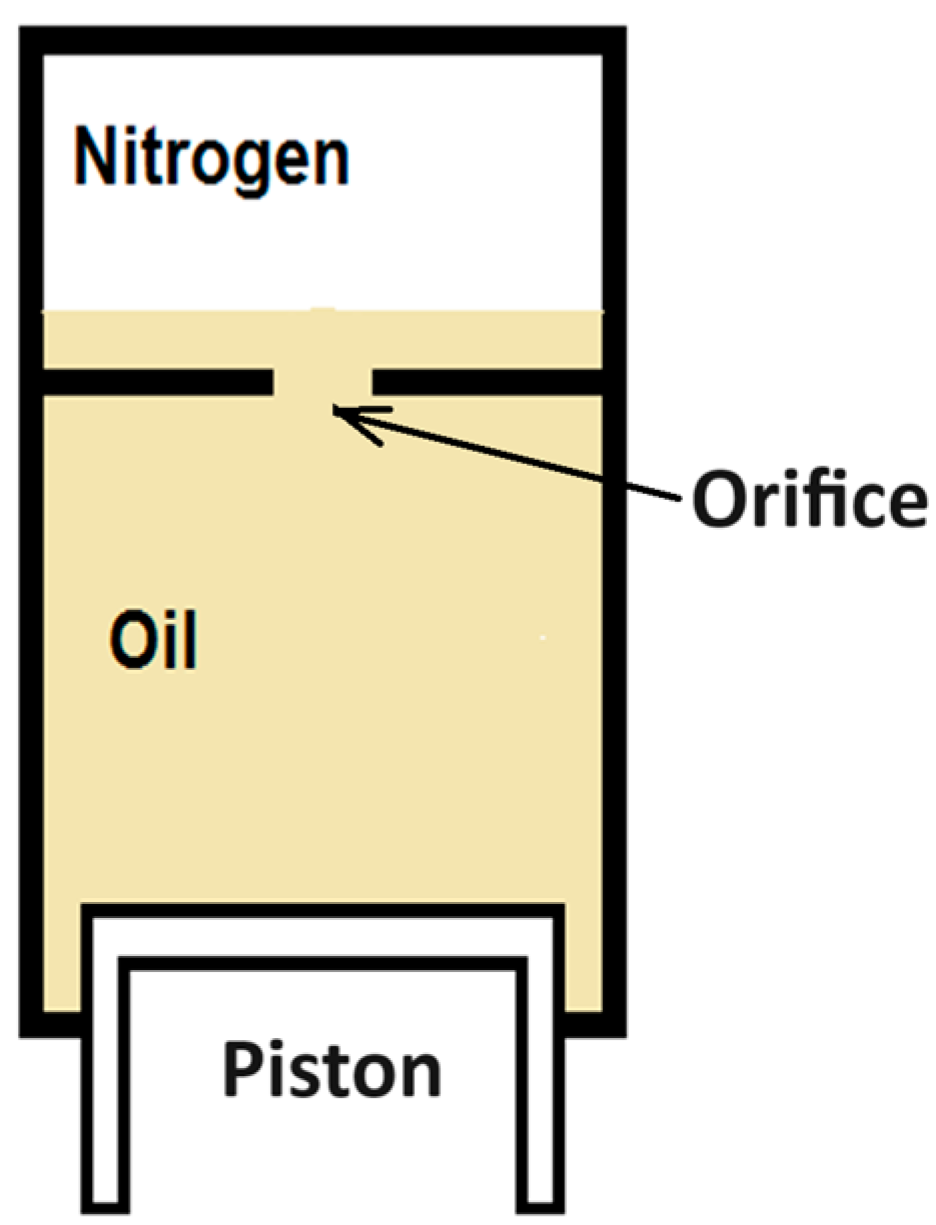
The basic functioning of an oleo-pneumatic shock strut involves two main stages: compression and recoil. Upon initial impact, the oil is forced against the compressed gas, absorbing the kinetic energy. As the gas compresses, it provides a cushioning effect, reducing the impact forces transmitted to the airframe. After the initial compression, the energy is further dissipated as the compressed gas forces the oil back through recoil orifices. The basic schematics of an oleo-pneumatic shock absorber are depicted in Figure 1.
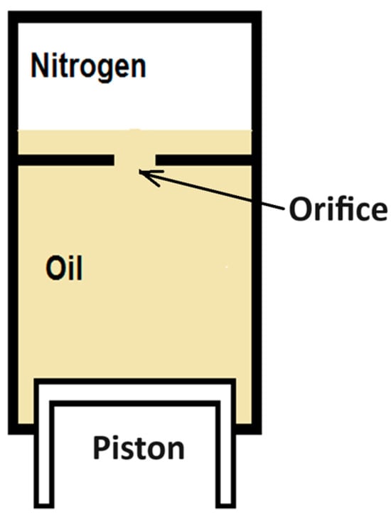
Figure 1.
Oleo-pneumatic shock absorber schematic.
The efficiency of an oleo-pneumatic shock absorber is significantly influenced by the design of the orifice through which the oil flows. Many designs incorporate a metering pin that varies the orifice area, ensuring that the load on the shock strut remains relatively constant during dynamic loading. This design aims to achieve near-constant gear efficiency, although practical efficiencies typically range between 80 and 90 percent.
For carrier-based UAVs, the design and performance of shock absorbers are even more critical. The unique landing environment of aircraft carriers, characterized by limited deck space and the need for rapid deceleration, imposes additional demands on the landing gear system. The shock absorbers must effectively manage the high impact forces to prevent structural damage and ensure the UAV’s operational readiness for subsequent missions [10].
When designing shock absorbers for UAVs, several factors need to be considered to optimize performance. These include the weight of the UAV, the expected landing speeds, and the nature of the landing surface. For high-altitude, long-endurance UAVs, such as the Global Hawk, advanced shock absorber design is employed to handle the significant kinetic energy dissipation during landing, and provide a smooth touchdown [15].
Recent research has focused on enhancing the performance of oleo-pneumatic shock absorbers through various means, including the optimization of the metering pin design, the incorporation of advanced materials, and the use of computational simulations to predict and improve performance. Studies have demonstrated that variable area orifices with metering pins can significantly improve the efficiency of energy absorption and dissipation compared to constant area orifices [16,17].
Additionally, computational fluid dynamics (CFDs) and multi-body dynamics simulations have been employed to model the behavior of shock absorbers under different landing conditions. These simulations help to understand the complex interactions between shock absorber components and the dynamic forces during landing, resulting in more refined and effective designs.
The design and layout of landing gear involves a complex iterative process aimed at optimizing weight distribution and positioning on an aircraft. This process ensures both static stability and dynamic performance, crucial for safe operation across various environmental and operational conditions [18].
The evolution of landing gear mechanisms, particularly the advancements in shock absorber technology, underscores their critical role in enhancing the safety and efficiency of aircraft operations. By integrating innovative designs and materials, landing gear systems continue to evolve, meeting the ever-increasing demands of modern aviation standards and regulations.
1.2. Landing Gear Importance in Aircraft Design
The design and functionality of landing gear systems are paramount in aircraft engineering, significantly influencing safety and performance. These systems must withstand high levels of stresses developed upon contact during landing, especially under challenging conditions such as high sink rates (vertical landing speed) and adverse weather. These dynamics are even more critical for carrier-based aircraft, due to higher sink rates and additional impact loads from ship motion and deck obstacles [19].
Landing gear design ensures the structural integrity and operational efficiency of aircraft throughout their lifespan. Abnormal landing conditions, like high sink rates and adverse weather, necessitate robust design considerations to manage significant impact loads effectively [20].
Carrier-based aircraft face harsher landing conditions than their land-based counterparts. Deck landings introduce complexities such as high sink rates, deck motion, and arresting gear interactions, imposing greater design stresses on landing gear system components. These systems must absorb increased impact loads and exhibit enhanced durability to maintain operational effectiveness [21].
Carrier-based aircraft face unique challenges during takeoff and landing to do with the confined and dynamic space of aircraft carrier decks. These challenges necessitate landing gear systems capable of withstanding higher impact loads and accommodating dynamic interactions between the aircraft and the carrier deck [22].
Designing landing gear for carrier-based applications involves addressing these unique challenges, specific to maritime environments and carrier operations. The sink rate of carrier-based aircraft is notably higher than that of their land-based counterparts, resulting in increased impact loads during deck landings. The dynamic interaction between the aircraft and the moving deck further complicates the load conditions, requiring meticulous analysis and design considerations [23].
Moreover, carrier-based aircraft operate in harsh environmental conditions, such as saltwater exposure and corrosive marine air. This necessitates the use of durable materials and protective coatings to enhance longevity and reliability.
Key considerations in the design process include ensuring the strength and reliability of the arresting gear and effectively managing the impact of deck motion on landing dynamics. The landing gear must integrate seamlessly with the arresting gear system, which imposes substantial loads on both the landing gear and the aircraft structure upon touchdown [21]. Robust shock absorption capabilities are crucial for safe and controlled landings.
In the context of UAVs, landing gear dynamics are crucial for precise autonomous landing capabilities. Designed to handle varied loads and impact conditions autonomously, UAV landing gears rely on advanced control algorithms [24] and robust mechanical designs to ensure safe and reliable landing.
1.3. Landing Gear Design for UAV Applications
The integration of landing gear systems in UAVs presents unique challenges, due to their specific operational requirements and constraints. Designed for autonomous operations, UAVs require landing gear systems capable of precise and reliable performance across diverse and potentially adverse conditions. This includes scenarios where autonomous landings are essential, such as carrier-based operations [9].
The design of UAV landing gear emphasizes lightweight yet robust performance. Advanced materials and technologies are crucial to achieve this balance, ensuring that the landing gear provides sufficient strength and shock absorption without adding unnecessary mass to the aircraft. Innovative design approaches are often employed to meet these demands, particularly in optimizing weight efficiency and enhancing reliability [25].
Moreover, the dynamic modeling and simulation of UAV landing gear systems play a pivotal role in their development. These simulations are essential for optimizing design parameters and reducing reliance on extensive physical testing. They help ensure that the landing gear can handle frequent and potentially hard landings, which is essential for UAVs performing missions requiring rapid deployment and recovery.
The design process often involves extensive simulation and testing to validate the landing gear’s performance under various conditions. Modern simulation tools enable the accurate modeling of landing gear dynamics, including factors such as extreme landing scenarios, variable runway conditions, and cross-wind effects [22]. These simulations help to reduce the number of required physical tests, saving time and cost while ensuring compliance with regulatory requirements.
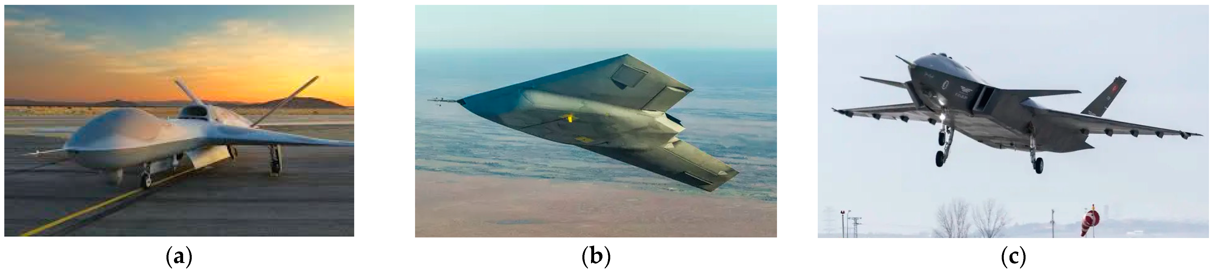
These considerations underscore the critical role of landing gear in the safe and efficient operation of carrier-based UAVs. Specific design parameters are guided by standards, and certification requirements are tailored to the unique operational demands of UAVs in carrier environments. Several 8000–9000 kg-class UAV examples are given in Figure 2. Like manned aircraft, UAVs are equipped with various propulsion systems tailored to their mission requirements. In that sense, carrier-based UAVs can utilize gas turbine engines [6]—such as turbofan [26] or turboprop [7] configurations —or electric propulsion systems [27], depending on operational needs and design constraints.
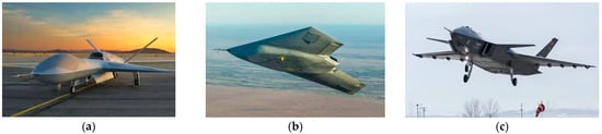
Figure 2.
Examples of UAVs in 8000–9000 kg class: (a) Predator C [28]; (b) Taranis [29]; and (c) Kizilelma [30].
1.4. Landing Gear Design Standards and Certification Requirements
The design and certification of aircraft landing gear are governed by stringent standards and regulations to ensure safety and performance. For military aircraft, standards such as MIL-A-8870, MIL-A-8863, and MIL-A-8862 outline the general and specific requirements for landing gear strength, rigidity, and shock absorption characteristics [31]. For civil aviation, the Federal Aviation Administration (FAA) and the European Aviation Safety Agency (EASA) provide comprehensive regulations through documents like FAR 23 and CS 23 for aircraft weighing less than 5670 kg (12,500 lb), and FAR 25/CS 25 for higher-weight aircraft [32]. These standards detail the load conditions, performance criteria, and testing requirements necessary for certification.
Carrier-based UAVs, in particular, must meet military or civil standards (sometimes both), considering their operational environments and mission profiles. Compliance with these standards ensures that the landing gear systems are robust, reliable, and capable of performing under the demanding conditions of typical carrier operations.
2. Materials and Methods
This section introduces usage examples of shock absorbers in manned aerial vehicles and UAVS with a focus on oleo-pneumatic types, continues with the explanation of the landing gear model developed, and finalizes with the input parameters and methodology in the next subsections.
2.1. Landing Gear Model
This section details the methodology used to model the landing gear as a mass–spring–damper system, a common approach for analyzing dynamic systems. The model is based on established principles and equations of motion that describe the interactions between the aircraft mass, shock absorber, and tire elements. This study focuses on the vertical dynamics of landing impacts to simplify the analysis and lay the groundwork for future work. The spin-up and horizontal dynamics were omitted due to their secondary influence on the primary goal of evaluating the oleo-pneumatic energy absorption system under typical carrier landing conditions. These factors will be included in follow-up research to provide a more comprehensive assessment. Additionally, this study primarily focused on the structural dynamics of landing gear systems for UAVs, without addressing the physiological and operational constraints applicable to manned aircraft. For instance, in the case of UAVs, the physiological tolerance of pilots to g-forces is not a constraint, allowing designers to focus solely on structural constraints and operational requirements. While UAV systems are still designed to absorb high forces without compromising the airframe, the absence of human occupants provides greater flexibility in defining the permissible acceleration limits. This flexibility enables UAVs to perform more aggressive maneuvers during both flight and landing.
2.1.1. Mass–Spring–Damper System
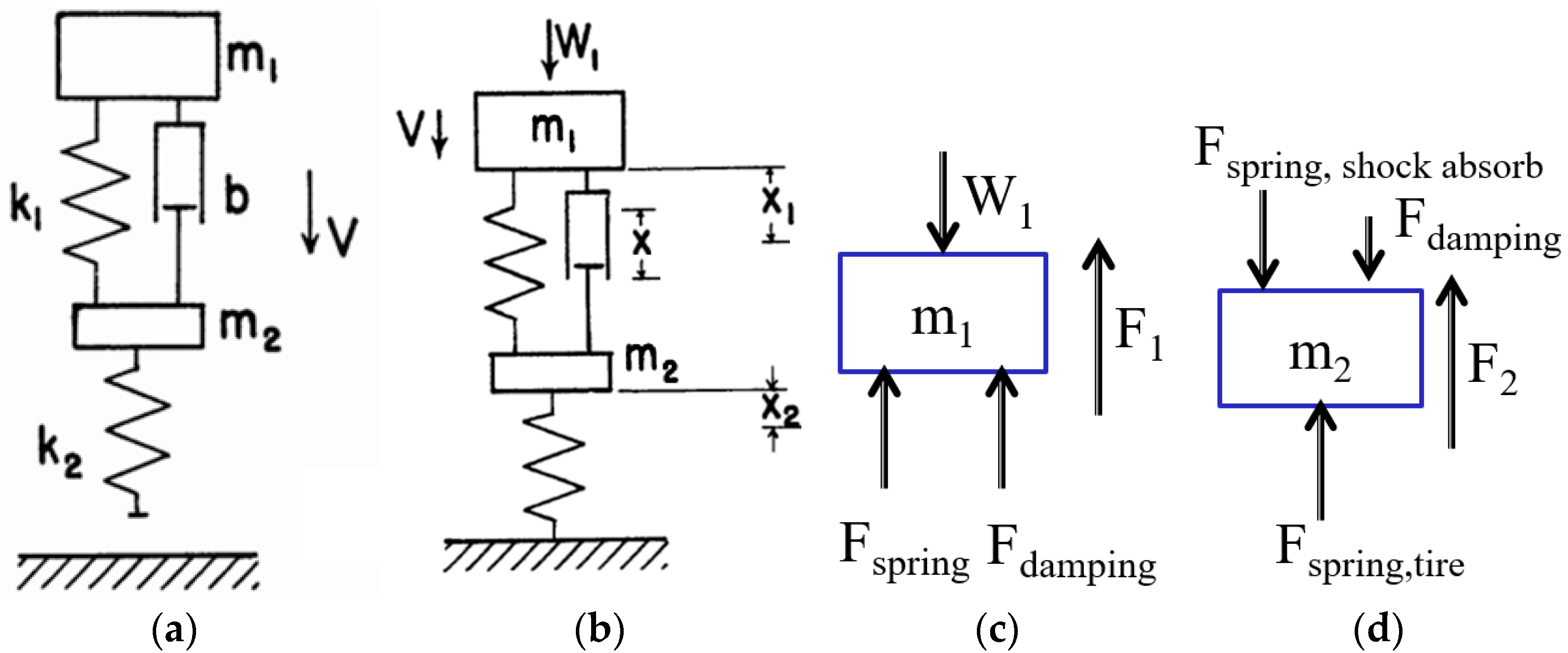
The landing gear consisting of a shock absorber is modeled as a two-degree-of-freedom mass–spring–damper system, as depicted in Figure 3. The system consists of the following elements [33,34]:
| m1 | Mass of the aircraft distributed to each landing gear (sprung mass); |
| m2 | Total mass of the wheel and tire group (unsprung mass); |
| k1 | Spring constant of the shock absorber; |
| k2 | Spring constant of the tire; |
| b | Damping coefficient of the shock absorber; |
| x | Displacement of the shock absorber; |
| x1 | Displacement of the aircraft; |
| x2 | Displacement of the wheel and tire group; |
| F1 | Net force on m1 (aircraft) per landing gear; |
| F2 | Net force on m2 (wheel and tire group); |
| g | Gravity; |
| V | Aircraft vertical speed (sink rate); |
| W1 | Aircraft weight minus lift force per landing gear. |
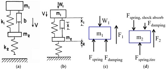
Figure 3.
(a) Mass–spring–damper model for MLG; (b) displacements; (c) resulting net force F1 on aircraft; and (d) resulting net force F2 on wheel and tire group.
The model aims to calculate F1 and F2, which are the resulting net forces acting on the aircraft (m1) and the wheel and tire group masses (m2), respectively. The displacements (x, x1, x2) of the shock absorber, aircraft, and wheel and tire group are also calculated, as shown in Figure 3. These calculations are essential for evaluating the performance of the landing gear in mitigating impact forces, as well as for determining the overall dynamic behavior of the system during touchdown.
The mass–spring–damper model provides several benefits for the design and analysis of UAV landing gear systems:
- -
- Predictive Analysis: Allows for the prediction of forces and displacements, aiding in the design of more robust landing gear;
- -
- Optimization: Facilitates the optimization of spring and damping constants to achieve desired performance characteristics;
- -
- Safety: Enhances safety by enabling the design of landing gear that can effectively absorb and dissipate impact energy, reducing the risk of structural damage.
2.1.2. Equations of Motion
The equations of motion for the system can be derived from Newton’s second law. For the mass m1 (aircraft mass), the net force F1 (see Figure 3) is given by the following equation:
By substituting the expressions for the spring and damping forces, the equations converts to:
The displacement x of the shock absorber is given by the difference between the displacements of the aircraft and the wheel:
where x1 and x2 are the displacements of the aircraft and the wheel, respectively.
The equation of motion for the aircraft mass m1 becomes the following:
Considering the lift force L acting on the aircraft, the weight W1 is as follows:
Thus, the modified equation of motion is as follows:
Similarly, for the mass m2 (wheel and tire group), the force F2 acting on m2 is given by the following equation:
Substituting the expressions for the forces, the equation converts to the following:
2.1.3. Equations of Motion for Wheel and Tire Group
Rewriting the equations for clarity, they are as follows:
2.2. Input Parameters and Methodology
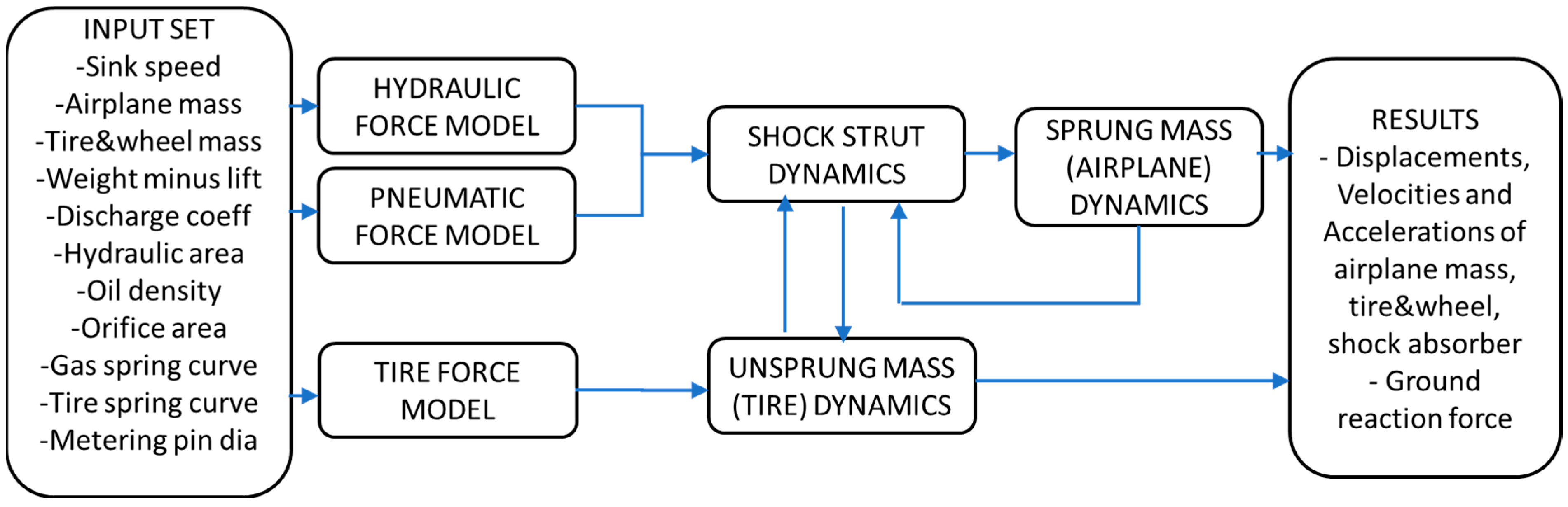
The flowchart of landing gear simulation is given in Figure 4, with the following modeling assumptions and simplifications:
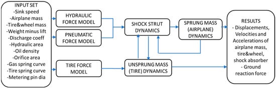
Figure 4.
Flowchart of landing gear simulation.
- Nonlinear Spring and Damping: The model includes nonlinear spring behavior (nitrogen gas adiabatic compression) for the shock absorber, as well as a nonlinear damping formulation for the shock absorber. The use of nonlinear spring behavior (representing the adiabatic compression of nitrogen gas) and nonlinear damping for the shock absorber is a realistic and necessary assumption to capture the dynamic energy absorption characteristics of the oleo-pneumatic system;
- Linear Spring model for the tire: Simplifying the tire as a linear spring assumes a constant stiffness throughout its deformation range. While this is a reasonable approximation for small deformations, it may not fully capture the nonlinearity of tire behavior under extreme loads, such as large deflections or material compression at high sink rates;
- Rigid Body Dynamics: The aircraft and wheel masses are treated as rigid bodies, neglecting any potential deformations. Treating the aircraft and wheel masses as rigid bodies simplifies the model and reduces computational complexity. However, this assumption neglects potential structural deformations of the aircraft and wheel assembly, which may occur under high-impact loads. These deformations could slightly alter the dynamic response and force distribution in real-world scenarios;
- Simplified Geometry: The complex geometries of the landing gear components are simplified into equivalent spring–damper systems. The reduction of complex landing gear geometries into equivalent spring–damper systems simplifies the mathematical formulation and allows for faster simulations. While this is appropriate for capturing the overall dynamic behavior, it may overlook localized effects, such as stress concentrations or structural interactions between landing gear components. These effects are typically addressed in detailed finite element models;
- Spin-up Forces: Wheel spin-up forces due to the rapid acceleration of the wheels upon touchdown are not included in the analysis. The omission of wheel spin-up forces assumes that their contribution to the overall dynamics is secondary compared to the vertical impact forces. This is a reasonable simplification for most carrier-based landing scenarios, where the vertical loads dominate. However, in cases involving high horizontal touchdown speeds, spin-up forces could influence the stress on the wheel and tire assembly.
2.2.1. Discharge Coefficient (Cd)
The discharge coefficient (Cd) is a critical parameter in the design of landing gear shock absorbers, as it influences the flow rate of hydraulic fluid through orifices, thereby affecting the damping characteristics. Cd is used to characterize the flow behavior of fluid through orifices or valves within the shock absorber system. It accounts for energy losses due to friction, turbulence, and other factors as the fluid passes through these restrictive components. The discharge coefficient directly influences the damping characteristics of the oleo-pneumatic system by determining the rate at which energy is dissipated during the compression and rebound phases. This parameter is critical for accurately modeling and optimizing the system’s performance, particularly in high-impact scenarios. For carrier-based UAVs, it is essential to accurately determine Cd to ensure effective energy dissipation during landing impacts. The shape of the orifice significantly impacts the discharge coefficient. Sharp-edged vs. rounded orifices can make a difference. According to a study by Ding et al. [11], the recommended values for Cd range from 0.632 to 0.707 for sharp-edged orifices, and 0.913 for rounded orifices. According to a NACA report [34], the validation of a landing gear model suggests a value of Cd equal to 0.9, which fits well with the experimental results. Therefore, for this study, the rounded orifice value of Cd will be utilized, as suggested by the NACA report.
2.2.2. Orifice Area
The orifice area is another vital parameter affecting the damping characteristics of the landing gear. According to Currey [13], as referenced in Conway’s book [35], the orifice area can be calculated using Equation (11). It is optimized during detailed calculations; however, being an initial estimation, it is computed as follows:
- Aorif: Orifice area (in2);
- A: Piston area (in2);
- r: Applicable load/static load;
- s: Total stroke (in);
- W: Shock absorber static load (lb).
2.2.3. Shock Absorber Piston Area (m2)
The piston area of the shock absorber is determined by the maximum static load and the nitrogen pressure. The use of static load to determine the piston area of the shock absorber, in conjunction with nitrogen pressure, is a deliberate choice to ensure that the shock absorber can reliably support the aircraft under steady-state conditions before accounting for dynamic impacts, and it is a simple approach suggested by Currey [13]. Given the pressurization with nitrogen, the piston area is derived as follows:
- A = piston area (in2);
- Fmax = maximum static load (lb);
- Pgas = nitrogen gas pressure (psi).
Using this area, the piston area and later diameter can be calculated. The shock absorber’s total piston and hydraulic area is then used to assess the pneumatic and hydraulic forces of the landing gear system. The initial gas pressure Pgas in the shock absorber is a crucial factor in determining the performance and response of the landing gear system. Currey [13] suggests that the initial shock strut pressure of nitrogen can be assumed as 1500 psi (10.34 MPa). However, this value may result in a very small-diameter piston area, which is not acceptable due to structural and mechanical strength and buckling reasons, and therefore should be modified within design iterations. The static position of the system can be around 16% of the available stroke value as advised by Currey [13], or should be around 1/3 of the total stroke at maximum weight, as advised by Conway [35]. In this study, after several design iterations, the static position of the system was taken as 1/3 of the total stroke. The initial gas pressure for MLG was taken as 1.6 MPa to have a shock absorber diameter of 99.2 mm. All input parameters used in the model are summarized in Table 1. The aircraft mass per main landing gear was assumed to be 50% for a two-point landing scenario. In a typical two-point symmetrical landing scenario, the weight of the aircraft is evenly distributed between the right and left main landing gear, with no contribution from the nose or tail landing gear. Assuming a 50% load per gear reflects this balanced distribution and simplifies the load distribution analysis.

Table 1.
Landing gear input parameters.
2.2.4. Shock Strut Stroke (M)
The stroke length of the shock strut is a fundamental parameter that influences the landing gear’s ability to absorb impact energy. Currey’s method proposes the following equation to calculate the stroke length (S):
- V: Velocity;
- g: Gravitational constant;
- St: Tire deflection;
- K: Lift to weight ratio;
- N: Load factor (assumed 6 for carrier-based aircraft);
- ns: Efficiency of strut (assumed ~0.8);
- nt: Efficiency of tire (assumed ~0.47).
Using these parameters, the stroke length is calculated to be 58 cm, including a safety buffer of 2.54 cm (1 in). In another study, Crenshaw [36] suggests that for a carrier-based gear with a sink rate requirement of 6–7.6 m/s (20–25 fps), a preliminary design with a 0.635 m (25 in) stroke is recommended for further study, as shown in Figure 5. For land-based landing gears, a much shorter stroke is advised for a typical 3.05 m/s (10 fps) sink rate. Carrier-based aircraft typically experience a load factor of 4 to 6 g due to their very high sink rates (6–7.6 m/s or 20–25 fps), whereas land-based aircraft generally have a load factor of around 2 to 3 g for 3.05–3.66 m/s (10–12 fps) sink rates. These values represent typical design limits and may vary slightly depending on specific aircraft models and their intended use. For example, the landing gear for the Fairchild Republic T-46A Trainer aircraft was designed to handle a sink rate of 3.96 m/s (13 fps) under limit conditions and up to 4.94 m/s (16.2 fps) under ultimate conditions [37]. Naturally, higher shock strut strokes are needed to absorb the high sink rates for carrier-based aircraft.
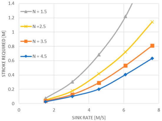
Figure 5.
Stroke vs. sink rate (adapted from [36]).
For this study, a 52.5 cm stroke (see Table 1) for MLG was found to be appropriate after the final analysis, which is close to initial estimations.
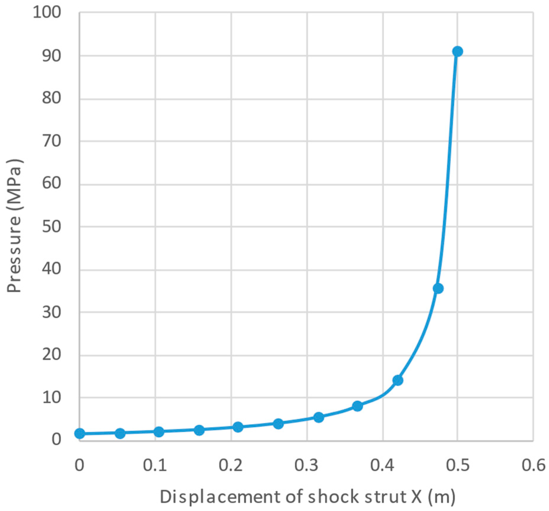
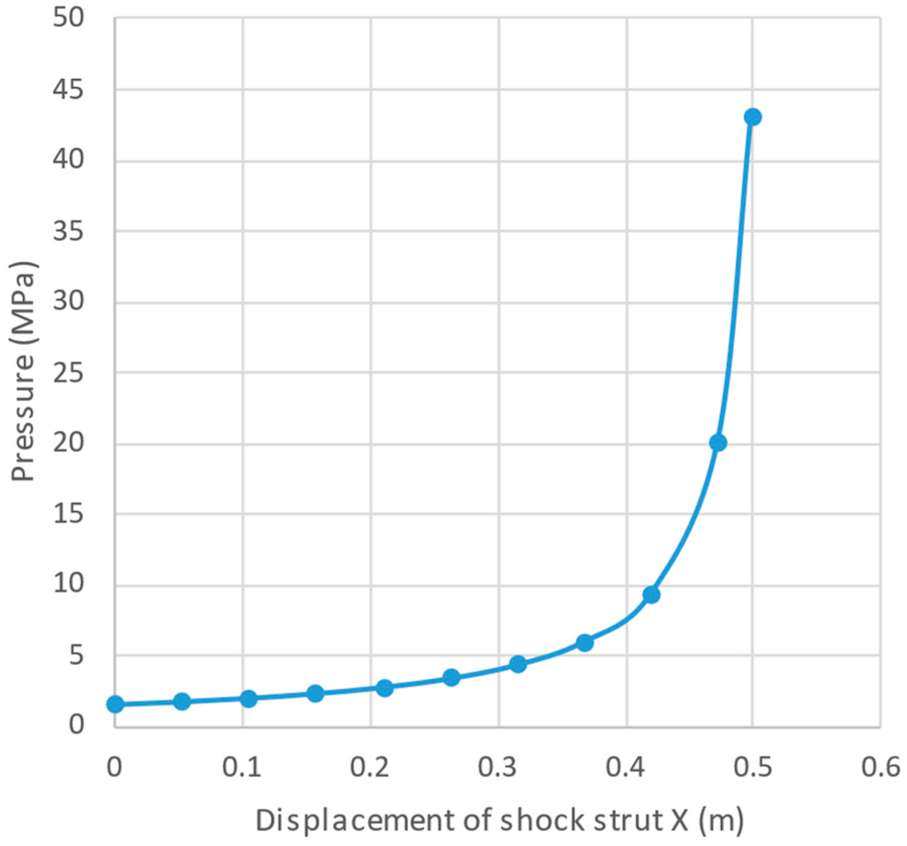
Gas Spring Curves
The behavior of the gas, typically nitrogen, acting as a spring can be modeled using adiabatic and isothermal processes, described by the equation Pvn = constant, where
- -
- n = 1.35 for adiabatic process (impact load);
- -
- n = 1.1 for isothermal process (static load).
An adiabatic process occurs when compression or expansion happens so rapidly that there is insufficient time for heat exchange with the surroundings. This condition is typical during impact loading scenarios, such as the high-speed compression of the gas in the shock absorber during a landing impact. Ahmad et al. [9] suggest that adiabatic exponent for diatomic gases (e.g., N2, O2, etc.) should be n = 1.40. However, they also note that, in practice, there is a small loss of heat to the surroundings, and therefore, the value of n typically falls between 1.0 and 1.40. Heerens [38] more specifically suggests a value for n = 1.35 for a shock with oil and gas separated during compression. Therefore, a value of n = 1.35 was assumed for this study and applied to all impact analyses presented in the following sections.
An isothermal process occurs when compression or expansion is slow enough to allow heat exchange with the surroundings, maintaining a constant temperature. This is typical during static loading conditions, such as when the landing gear supports the aircraft while stationary. The value n = 1.1 is slightly higher than the theoretical isothermal exponent (n = 1.0) due to real-world conditions where complete isothermal behavior is not achieved, and slight temperature variations occur. This value represents near-isothermal behavior commonly seen in applications where heat transfer mechanisms are active but not instantaneous. However, the value n = 1.1 was not used for this study, because it is not for the impact analyses, but only for the static loading conditions.
The compression curves of the nitrogen gas are illustrated in Figure 6 and Figure 7. In the subsequent impact analysis, the behavior of the nitrogen gas within the shock absorber was modeled and applied as an adiabatic process.

Figure 6.
Nitrogen gas curve for MLG: (adiabatic).

Figure 7.
Nitrogen gas curve for MLG: (isothermal).
To analyze the performance of the landing gear system, numerical simulations are conducted using the derived equations of motion. These simulations help predict the dynamic response of the landing gear under various landing scenarios, including different descent velocities (sink rates) and lift/weight conditions. This approach is supported by various studies [33,34]. As suggested earlier, according to the civil certification requirements established by the European Union Aviation Safety Agency (EASA), aircraft weighing more than 5670 kg (12,500 lb) are certified under CS-25 [39]. While civil certification is not mandatory for UAVs, the test cases from these requirements can still be used for demonstration and validation purposes due to their similarity. Additionally, for this study, military requirements such as MIL-A-8862A and MIL-A-8863 should be included for carrier-based aircraft. The sink rate serves as the primary input for landing impact scenarios and is specified in standards such as MIL-A-8863 and CS-25. The maximum acceleration of the aircraft is not explicitly defined in these standards, as it is a design choice aimed at ensuring the aircraft can withstand the specified loads without sustaining structural damage. Other parameters, such as braking values (horizontal force components), landing attitude angle, and horizontal landing speed, were excluded from the vertical impact analysis due to their secondary influence on the primary objective of evaluating the oleo-pneumatic energy absorption system under typical carrier landing conditions. These excluded parameters can be considered in future studies. Consequently, the requirements for this study were selected and are presented in Table 2, with a primary focus on sink rate and the lift-to-weight ratio at the corresponding sink rate, as explained below:
Table 2.
Simulation cases.
CS 25.473 (a) (2) and CS 25.473 (a) (3): These refer to specific subclauses within the European Union Aviation Safety Agency’s (EASA) Certification Specifications (CS-25) for large airplanes [39]. They outline the design load requirements for landing gear systems under different load conditions. Clause (a) (2) specifies the “limit descent velocity at the design landing weight,” which corresponds to the maximum weight for landing conditions at the maximum descent velocity. Clause (a) (3) specifies the “limit descent velocity at the design take-off weight,” which corresponds to the maximum weight for landing conditions at a reduced descent velocity. Consequently, landing gear requirements for civil applications are typically referenced as 3.05 m/s (10 fps) for CS 25.473 (a) (2) and 1.83 m/s (6 fps) for CS 25.473 (a) (3), representing the testing velocities for these scenarios.
CS 25.723 (b): This clause pertains to the energy absorption testing requirements for landing gear. It specifies the minimum energy the landing gear system must be capable of absorbing during landing impact to ensure safety and structural integrity under specified landing conditions. The clause states: “The landing gear may not fail in a test demonstrating its reserve energy absorption capacity, simulating a descent velocity of 3.7 m/s (12 fps) at design landing weight, assuming aircraft lift not greater than the aircraft weight acting during the landing impact” [39]. The requirement from CS 25.723 (b) can therefore be referenced as a sink rate of 3.66 m/s (12 fps).
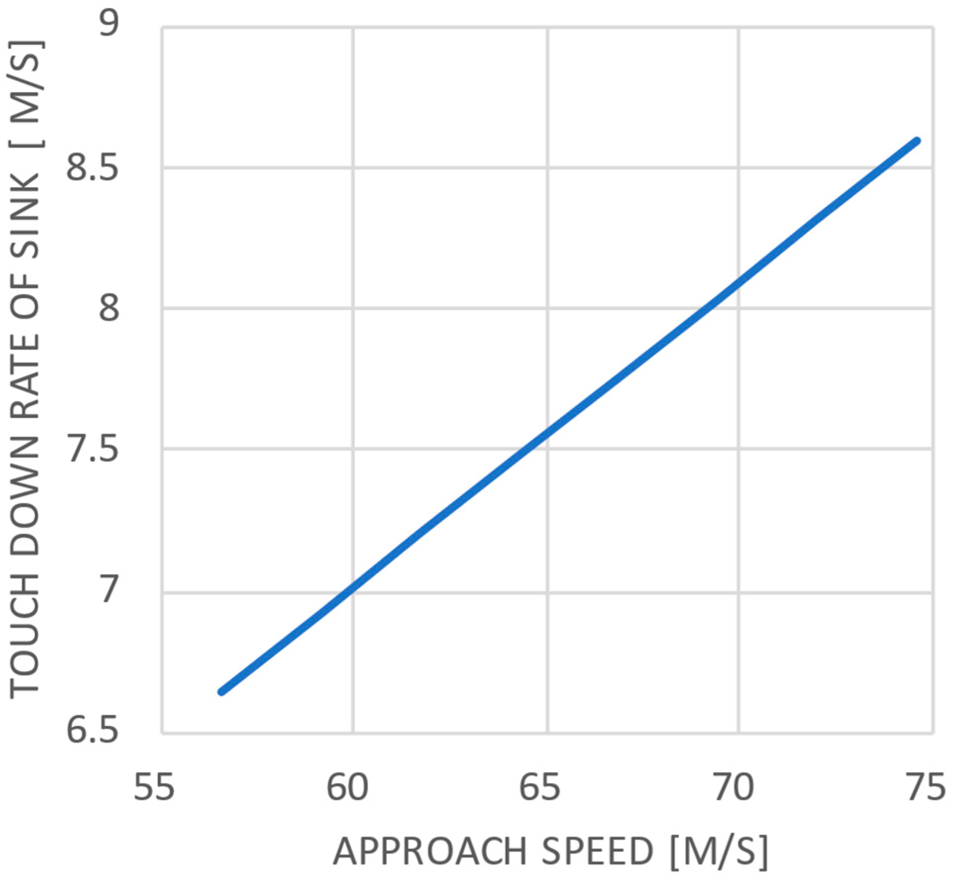
MIL-A-8863: This U.S. military specification outlines the design, performance, and testing requirements for aircraft landing gear systems. Unlike CS-25, MIL-A-8863 is tailored for military applications and incorporates more stringent criteria to address the unique demands of military operations, including higher sink rates and harsher operational environments. For carrier-based aircraft, sink rates may range from 22 to 28 fps [36], as shown in Figure 8. Sink rates are calculated in accordance with MIL-A-8863 [40], and are significantly higher compared to those for land-based aircraft. For an assumed approach speed of 64.3 m/s (125 knots), a sink rate of 7.47 m/s (24.5 fps) will be considered and included as a simulation case in Table 2.

Figure 8.
Sink rate vs. approach speed (adapted from [36]).
Based on the above discussion and design parameters, a Matlab/Simulink model was developed to simulate the dynamics of the landing gear system, solving the coupled equations of motion for the sprung (airplane) and unsprung (tire and wheel assembly) masses. The model incorporates key components of the oleo-pneumatic shock absorber, including gas compression (modeled with adiabatic and isothermal processes), fluid flow through the orifice (governed by the discharge coefficient Cd), and tire stiffness and damping. The governing equations were parameterized using the data presented in Table 1, with boundary conditions based on the sink rates and lift-to-weight ratios outlined in Table 2.
The simulation framework was designed to capture dynamic impact output parameters (e.g., impact forces, displacements, etc.), with adiabatic conditions applied to account for rapid compression. Outputs such as vertical acceleration, displacement, and forces on the aircraft body were analyzed for various sink rates, as specified in Table 2. Figure 9 provides an overview of the Simulink model.
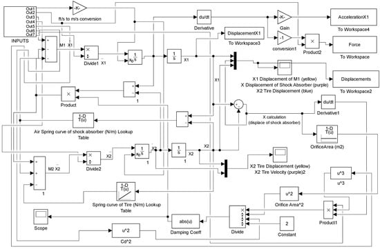
Figure 9.
Developed Simulink model for the landing gear.
3. Results and Discussion
In this section, the results of the genuinely developed landing gear Simulink model are presented. This study primarily focuses on the simulation results, as no tests were conducted within the scope of this research.
Main Landing Gear Simulation
By carefully considering these input parameters and their respective methodologies, the dynamics of landing gear systems in carrier-based UAVs were analyzed, leading to the following results.
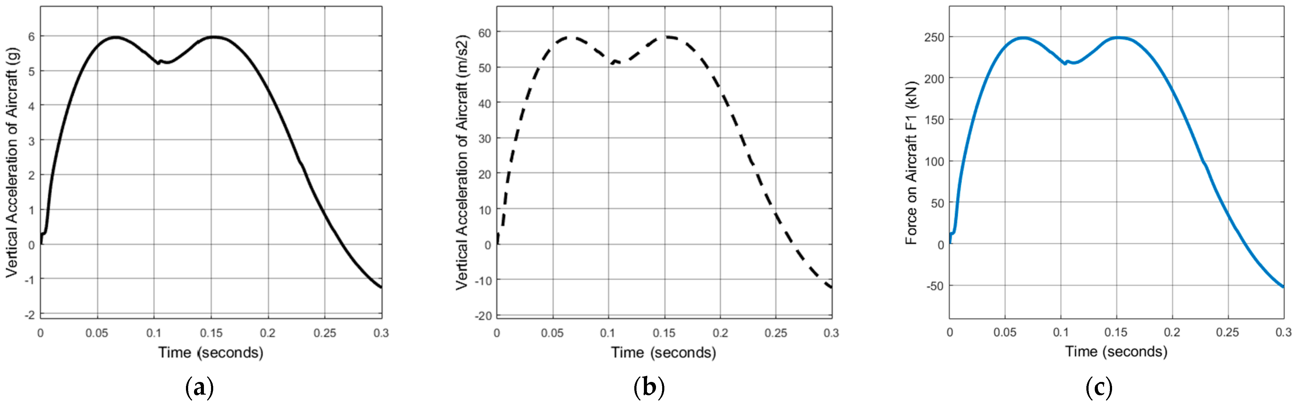
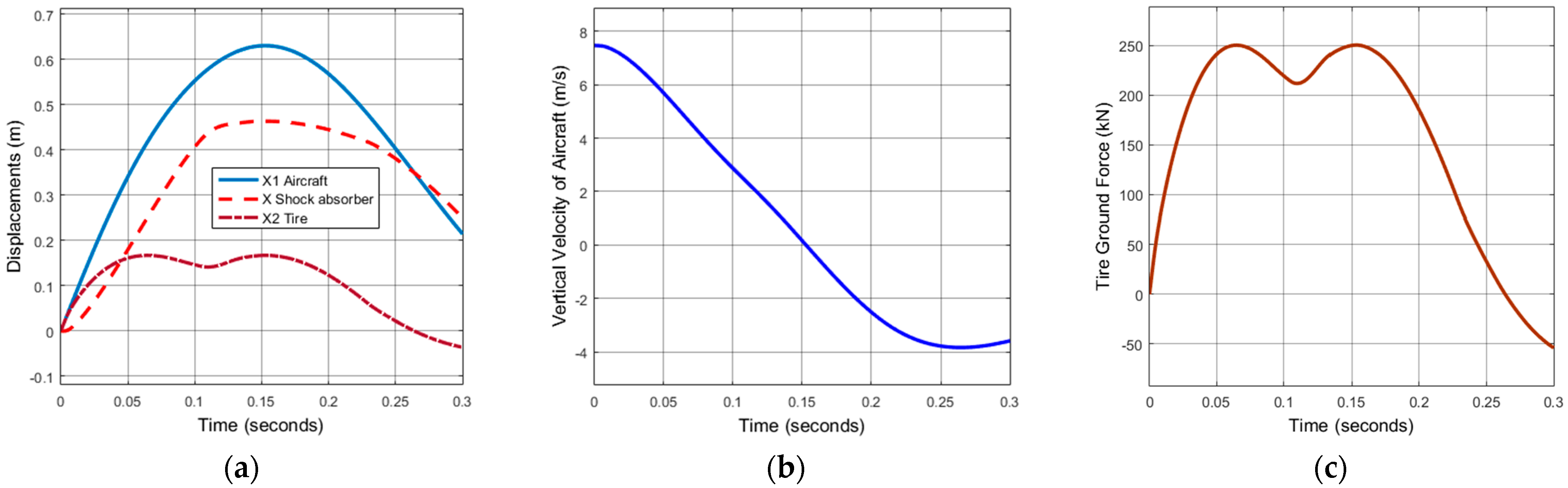
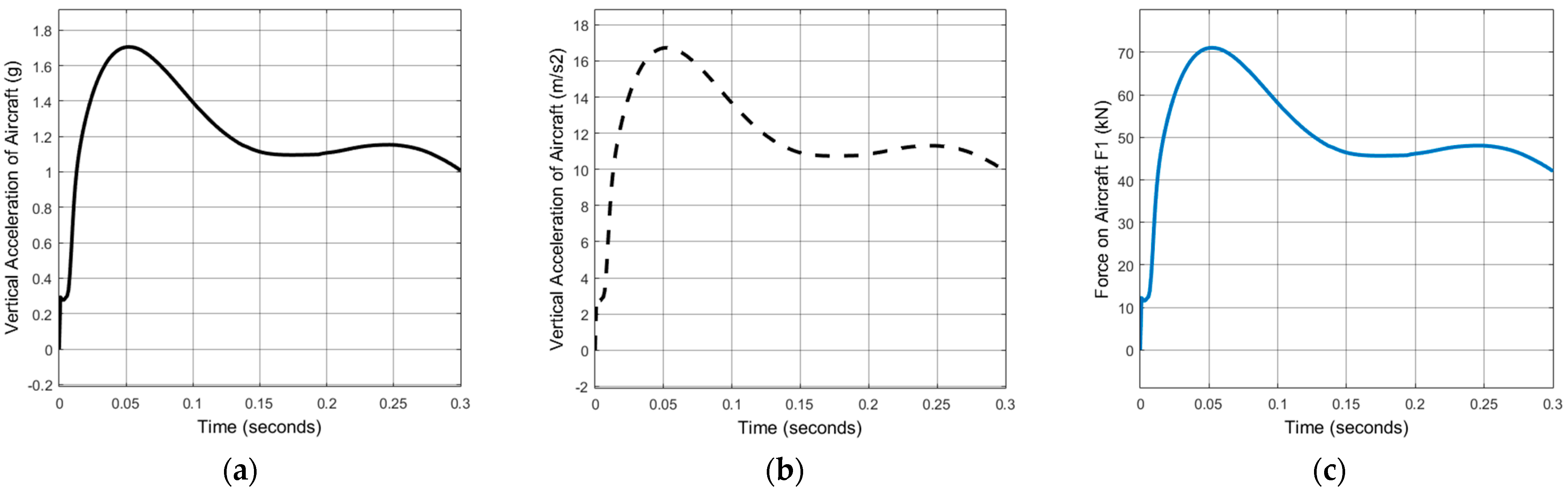
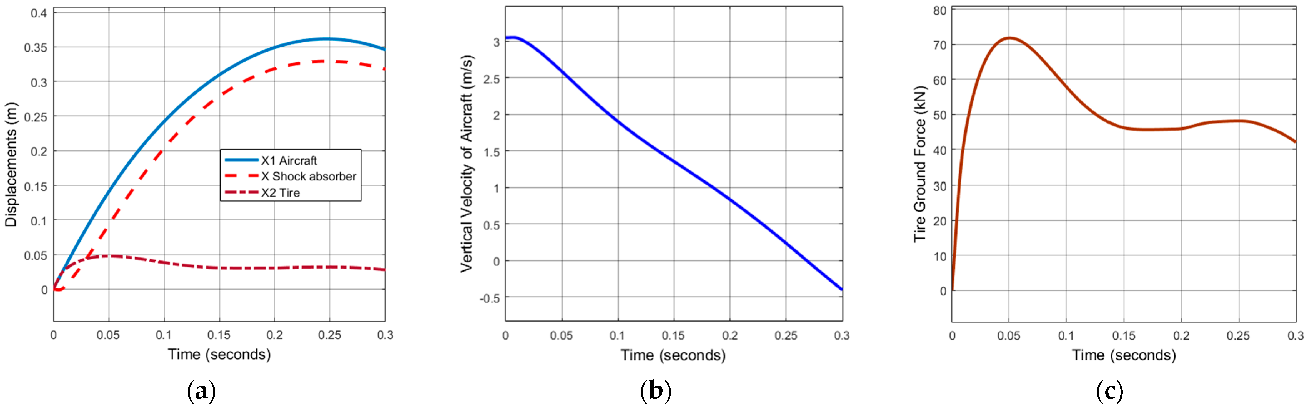
- Case 1: Sink rate of 24.5 fps (7.47 m/s)
Figure 10 and Figure 11 present the results for the most severe sink rate analyzed, 7.47 m/s (24.5 fps), as required by MIL-A-8863. As previously mentioned, this high sink rate is typically applicable to carrier-based military aircraft (not for commercial land-based aircraft). In this scenario, the maximum vertical acceleration reached 6 g (Figure 10a), consistent with the sizing calculations, as the load factor was assumed to be 6. This indicates that the shock absorber effectively mitigates the impact forces at this velocity. Under these conditions, the maximum force on the aircraft body was calculated as 250 kN (Figure 10c). In Figure 11a, displacements are shown with respect to time during the impact. As the impact force increased, the displacements also increased, with the aircraft displacement reaching a maximum of 0.63 m, while the tire displacement reached a maximum of 0.16 m. The maximum shock absorber displacement was approximately 0.46 m, compared to the maximum strut displacement of 0.525 m, as specified in Table 1. To reduce the 6 g load factor, the maximum strut displacement should be increased as a design input.
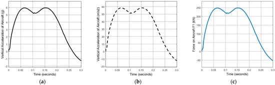
Figure 10.
Case 1: (a) acceleration of aircraft in g; (b) acceleration of aircraft (UAV) in m/s2; and (c) force on aircraft.
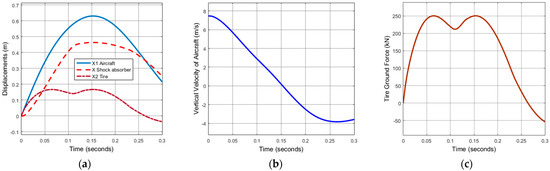
Figure 11.
Case 1: (a) displacements; (b) vertical velocity of aircraft (UAV) in m/s; and (c) tire force on ground.
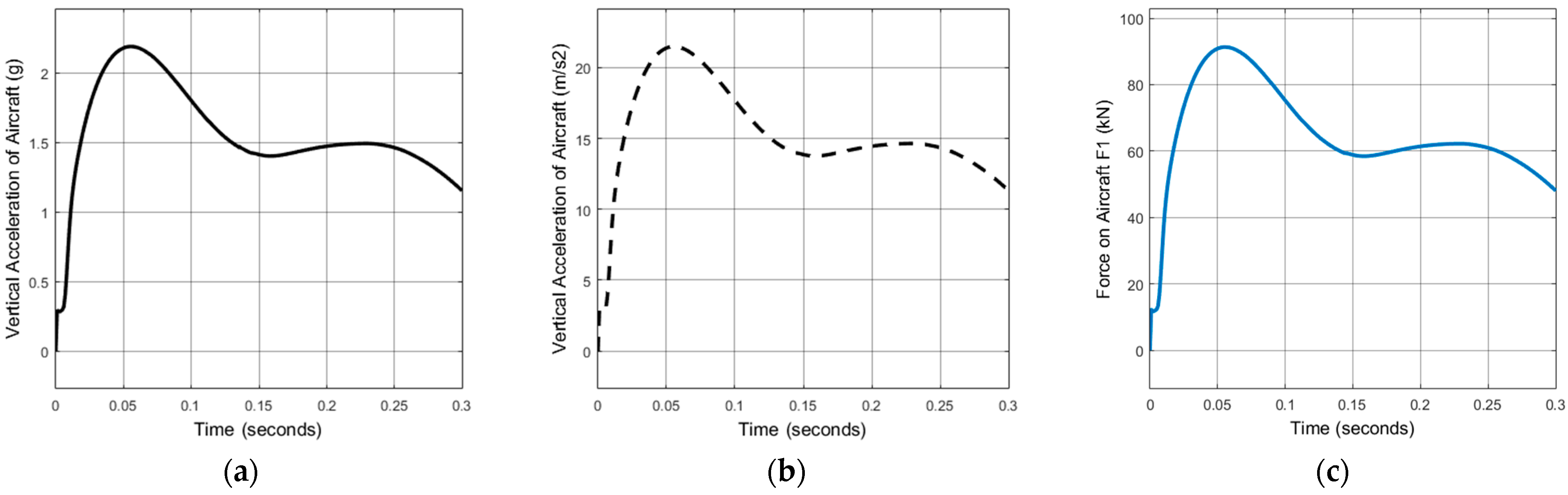
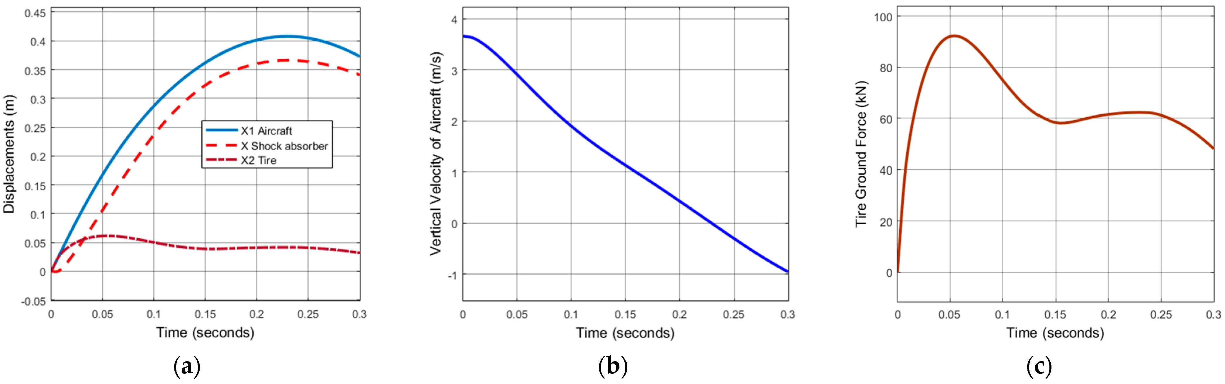
- Case 2: Sink rate of 3.66 m/s (12 fps)
This condition is a land-based operation requirement per CS 25.723 (b), which is the highest certification standard for commercial aircraft. Figure 12 and Figure 13 illustrate the simulation outcomes at a sink rate of 3.66 m/s (12 fps). The maximum vertical acceleration reached 2.19 g, which is well below the assumed constraint of 6 g. The maximum force on the aircraft body was calculated to be 91 kN. In Figure 13a, displacements are shown with respect to time during the impact. The maximum aircraft displacement reached 0.41 m, while the maximum tire displacement was 0.06 m. The maximum shock absorber displacement was approximately 0.36 m for this case. This case demonstrates that the shock absorber effectively mitigates the impact forces at this speed, although it is not the most severe condition.

Figure 12.
Case 2: (a) acceleration of aircraft in g; (b) acceleration of aircraft (UAV) in m/s2; and (c) force on aircraft.
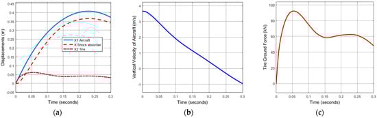
Figure 13.
Case 2: (a) displacements; (b) vertical velocity of aircraft (UAV) in m/s; and (c) tire force on ground.
- Case 3: Sink rate of 3.05 m/s (10 fps)
Figure 14 and Figure 15 illustrate the outcomes for a sink rate of 3.05 m/s (10 fps), as specified by CS 25.473 (a) (2). The maximum vertical acceleration reached 1.7 g, and the maximum force exerted on the aircraft body was determined to be 71 kN. In Figure 15a, displacements are shown with respect to time during the impact. The maximum aircraft displacement reached 0.36 m, while the maximum tire displacement was 0.05 m. The maximum displacement of the shock absorber was recorded at 0.33 m. While a sink rate of 10 fps represents one of the lower requirements for carrier-based aircraft, it stands as the second highest certification criterion for commercial aircraft.
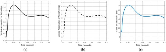
Figure 14.
Case 3: (a) acceleration of aircraft in g; (b) acceleration of aircraft (UAV) in m/s2; and (c) force on aircraft.
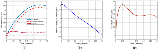
Figure 15.
Case 3: (a) displacements; (b) vertical velocity of aircraft (UAV) in m/s; and (c) tire force on ground.
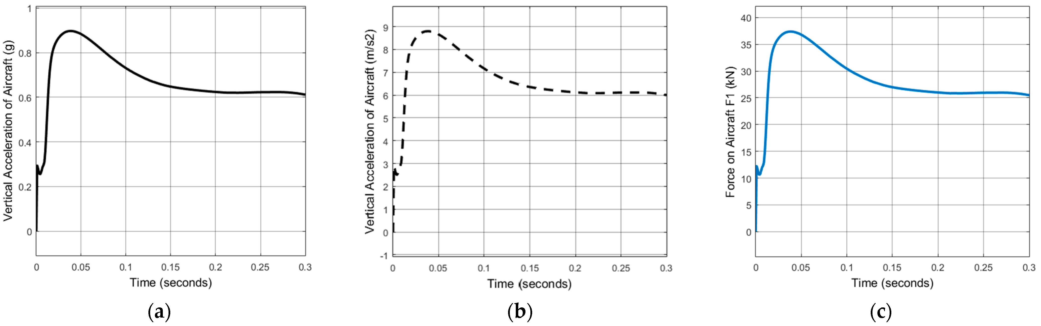
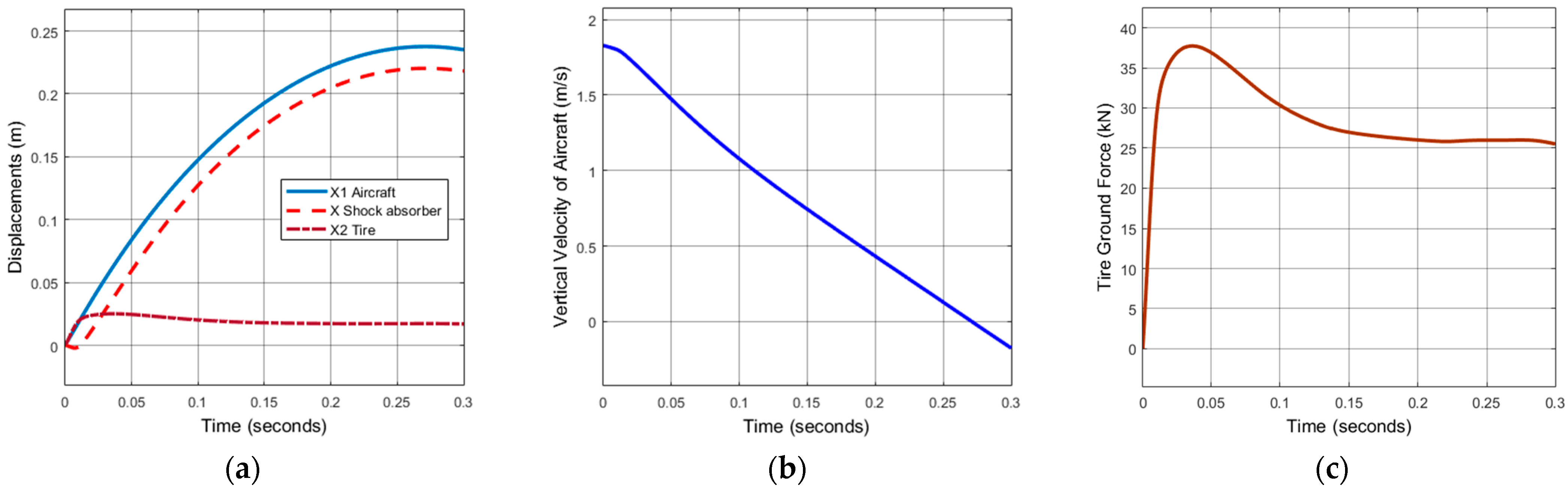
- Case 4: Sink rate of 1.83 m/s (6 fps)
Figure 16 and Figure 17 show the results for a sink rate of 1.83 m/s (6 fps), as per CS 25.473 (a) (3). The maximum vertical acceleration was determined to be 0.9 g, and the maximum force exerted on the aircraft body was calculated to be 37 kN. In Figure 17a, displacements are shown with respect to time during the impact. The maximum aircraft displacement reached 0.24 m, while the maximum tire displacement was 0.025 m. The maximum displacement of the shock absorber was calculated to be 0.22 m. These values are the lowest observed among all the cases studied, demonstrating the system’s response under the specified test conditions.
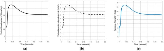
Figure 16.
Case 4: (a) acceleration of aircraft in g; (b) acceleration of aircraft (UAV) in m/s2; and (c) force on aircraft.
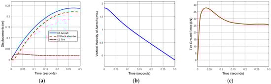
Figure 17.
Case 4: (a) displacements; (b) vertical velocity of aircraft (UAV) in m/s; and (c) tire force on ground.
The acceptable load factor and impact force values for landing vary between land-based and carrier-based aircraft due to the different operating environments and landing conditions they encounter. Carrier-based aircraft, such as those used by the Navy, are designed to withstand much higher g-forces due to the harsher conditions of carrier landings. The maximum landing load factors for carrier-based aircraft are usually in the range of 4 to 6 g. This higher tolerance is necessary because carrier landings involve more abrupt deceleration and impact forces as the aircraft catches the arrestor cable on the deck. For a typical land-based commercial aircraft, the maximum design landing load factor is around 2 to 3 g. This range ensures that the aircraft can handle the normal variations in landing impacts without structural damage.
The simulations demonstrate that the landing gear system effectively dampens the impact forces across a range of descent velocities typical for carrier-based UAV operations. The recorded vertical accelerations consistently meet or exceed the design constraints, underscoring the robustness of the shock absorber design.
The ability of the shock absorber to maintain displacements below the design constraints indicates its reliability in ensuring the structural integrity of the UAV during landing maneuvers. These results are crucial for the operational safety and longevity of both the UAV structure and its payload.
Based on the findings, the design parameters derived from the literature and implemented in the simulation prove their adequate performance for handling typical carrier-based UAV landing scenarios. However, further refinements could focus on optimizing the shock absorber characteristics to potentially enhance performance margins without compromising other design aspects.
The Matlab/Simulink simulations provide valuable insights into the landing dynamics of carrier-based UAVs, specifically regarding the performance of shock absorbers under varying descent velocities. The results confirm that the current design effectively meets or exceeds the specified constraints, ensuring safe and reliable operation during landing maneuvers.
4. Conclusions
The dynamics of landing gear systems for carrier-based Unmanned Aerial Vehicles (UAVs) present a unique set of challenges and opportunities. This study explored the design, analysis, and performance of oleo-pneumatic shock absorbers specifically tailored for an 8500 kg UAV, considering both carrier and land-based operations. The insights gained offer valuable perspectives on optimizing landing gear systems for varied and demanding operational environments.
Carrier-based landing gears must endure significantly more robust conditions than their land-based counterparts, necessitating designs that are inherently more robust. The study highlighted the weight penalties associated with these robust designs, which are a critical consideration for fighter aircraft, where weight efficiency is paramount. However, the potential for cost reduction through multi-service application designs and parts usage presents a promising avenue. The concept of common landing gear components across different service branches, though historically challenging, remains an attractive proposition.
The comprehensive design process for oleo-pneumatic main landing gear detailed in this study can serve as a blueprint for similar systems in other aircraft. The design process encompassed several critical aspects:
- Shock Absorber Strut Sizing: The study utilized both isothermal and polytropic gas models to calculate the variation in pneumatic pressure and air spring force with stroke length under static and dynamic loadings. This dual approach provided a thorough understanding of the behavior of the shock absorber under different conditions;
- Spring and Damping Characteristics: The oleo-pneumatic shock absorber exhibited nonlinear spring characteristics, which preclude the use of mechanical springs as alternatives. Mechanical dampers are less efficient compared to the oleo-pneumatic shock absorber. This underscores the superior performance of oleo-pneumatic systems in managing landing impacts;
- Impact Force Analysis: The impact force calculations, in accordance with FAR 25, ensured the landing gear’s compliance with airworthiness standards. The study’s drop dynamic model, solved using numerical integration, provided insights into the dynamic response of the landing gear system during landing.
The study identifies several areas for future research that could further enhance the design and performance of landing gear systems for UAVs and other aircraft:
- Automated Loads and Stress Analysis: Improvements in automated loads and stress analysis tools are crucial for rapidly quantifying landing gear weight as a function of required capability. These tools should be integrated into the earliest design stages to ensure optimal performance and weight efficiency;
- Active Control Systems: The development of actively controlled landing gear systems offers significant potential for vibration alleviation during landing. Various control schemes, including active orifice concepts, could be evaluated to dynamically adjust the damping characteristics of the landing gear in response to ground disturbances;
- Multi-Service Application: Further studies should explore the inherent capabilities of gears designed for shipboard operations to assess their benefits for use on rough runways. This could support the goal of creating common landing gear components that are efficient and cost-effective across different service branches.
The practical implications of this research are significant for the design and operation of UAVs and other aircraft operating in diverse environments. The robust and efficient design of oleo-pneumatic landing gears can enhance the operational performance and safety of these aircraft. By addressing the weight penalties associated with robust designs and exploring multi-service applications, the aerospace industry can achieve cost savings and improved resource utilization.
Furthermore, the insights gained from the comprehensive analysis of shock absorber characteristics and performance can inform the development of more advanced and capable landing gear systems. The focus on both static and dynamic loadings, as well as the detailed examination of spring and damping behaviors, provides a solid foundation for future innovations in landing gear technology.
In summary, this study provides a thorough examination of the design and dynamics of oleo-pneumatic landing gears for carrier-based UAVs. The research underscores the importance of robust and efficient designs that can withstand the demanding conditions of carrier-based UAV operations while remaining adaptable for land-based use. Future research should continue to explore the potential of active control systems and multi-service applications to further enhance landing gear performance and efficiency. By leveraging advanced modeling tools and comprehensive analysis techniques, the aerospace industry can continue to innovate and improve the safety and effectiveness of landing gear systems for UAVs and other aircraft.
Author Contributions
Conceptualization, A.D., F.Y., J.M., R.P., S.O., A.M. and M.O.; methodology, A.D.; software, A.D.; validation, A.D.; formal analysis, A.D.; investigation, A.D.; data curation, A.D.; writing—original draft preparation, A.D., F.Y., J.M., R.P., S.O., A.M. and M.O.; writing—review and editing, A.D., F.Y., J.M., R.P., S.O., A.M. and M.O.; visualization, A.D.; supervision, A.D.; project administration, A.D., F.Y., J.M., R.P., S.O., A.M. and M.O.; funding acquisition, A.M. and M.O. All authors have read and agreed to the published version of the manuscript.
Funding
The APC was funded by the American University of the Middle East.
Data Availability Statement
The original contributions presented in this study are included in the article. Further inquiries can be directed to the corresponding author.
Conflicts of Interest
The authors declare no conflicts of interest.
References
- Wei, X. An Overview of Researches on Deck-Landing of Carrier-Based Aircrafts. In Proceedings of the 2013 International Powered Lift Conference, Los Angeles, CA, USA, 12–14 August 2013; American Institute of Aeronautics and Astronautics: Reston, VA, USA, 2013. [Google Scholar]
- Dinc, A.; Gharbia, Y. Dynamic Modeling of Main Landing Gear of a High-Altitude Long Endurance UAV. In New Achievements in Unmanned Systems. ISUDEF 2021. Sustainable Aviation; Karakoc, T.H., Yilmaz, N., Dalkiran, A., Ercan, A.H., Eds.; Springer: Cham, Switzerland, 2023; pp. 239–248. ISBN 9783031299339. [Google Scholar]
- Fahlstrom, P.G.; Gleason, T.J. Introduction to UAV Systems, 4th ed.; John Wiley & Sons: Chichester, UK, 2012; ISBN 9781119978664. [Google Scholar]
- Karali, H.; Inalhan, G.; Tsourdos, A. Advanced UAV Design Optimization Through Deep Learning-Based Surrogate Models. Aerospace 2024, 11, 669. [Google Scholar] [CrossRef]
- Sui, L.; Sun, Y.; Kang, M. Analysis and Experimental Study for Fatigue Performance of Wing-Fuselage Connection Structure for Unmanned Aerial Vehicle. Aerospace 2024, 11, 826. [Google Scholar] [CrossRef]
- Dinc, A.; Gharbia, Y. Global Warming Potential Estimations of a Gas Turbine Engine and Effect of Selected Design Parameters. In Proceedings of the ASME 2020 International Mechanical Engineering Congress and Exposition, Atlanta, GA, USA, 16 November 2020; Volume 8, pp. 1–7. [Google Scholar] [CrossRef]
- Dinc, A. Sizing of a Turboprop Unmanned Air Vehicle and Its Propulsion System. J. Therm. Sci. Technol. 2015, 35, 53–62. [Google Scholar]
- Wen, Z.; Zhi, Z.; Qidan, Z.; Shiyue, X. Dynamics Model of Carrier-Based Aircraft Landing Gears Landed on Dynamic Deck. Chinese J. Aeronaut. 2009, 22, 371–379. [Google Scholar] [CrossRef]
- Ahmad, M.A.; Shah, S.I.A.; Shams, T.A.; Javed, A.; Rizvi, S.T.U.I. Comprehensive Design of an Oleo-Pneumatic Nose Landing Gear Strut. Proc. Inst. Mech. Eng. Part G J. Aerosp. Eng. 2021, 235, 1605–1622. [Google Scholar] [CrossRef]
- Dinc, A.; Gharbia, Y. Effects of Spring and Damper Elements in Aircraft Landing Gear Dynamics. Int. J. Recent Technol. Eng. 2020, 8, 4265–4269. [Google Scholar] [CrossRef]
- Ding, Y.W.; Wei, X.H.; Nie, H.; Li, Y.P. Discharge Coefficient Calculation Method of Landing Gear Shock Absorber and Its Influence on Drop Dynamics. J. Vibroeng. 2018, 20, 2550–2562. [Google Scholar] [CrossRef]
- Heininen, A. Modelling and Simulation of an Aircraft Main Landing Gear Shock Absorber. Master’s Thesis, Tampere University of Technology, Tampere, Finland,, 2015. [Google Scholar]
- Currey, N.S. Aircraft Landing Gear Design: Principles and Practices; American Institute of Aeronautics and Astronautics: Washington, DC, USA, 1988; ISBN 978-0-930403-41-6. [Google Scholar]
- Uguzo, S.O. A-9 Dragonfly Nose Landing Gear Design. Master’s Thesis, Cranfield University, Bedford, UK, 2010. Available online: https://www.academia.edu/29003167/CRANFIELD_UNIVERSITY_A_9_DRAGONFLY_NOSE_LANDING_GEAR_DESIGN (accessed on 10 June 2024).
- Ötkur, M.; Dinc, A. Performance Modelling of Landing Gear and Suspension System of a Flying Car for Landing and Bump Passing Manoeuvres. Eng. Mach. 2022, 63, 616–632. [Google Scholar] [CrossRef]
- Dinc, A. Metering Pin Diameter Optimization of an Aircraft Landing Gear Shock Absorber. Eskişehir Tech. Univ. J. Sci. Technol. B-Theor. Sci. 2021, 9, 37–46. [Google Scholar] [CrossRef]
- Patel, J.; Shetty, D.; Menghani, R.; Barve, S. Optimization of an Oleo-Pneumatic Shock Absorber for Main Landing Gear of a Commercial Aircraft. SSRN Electron. J. 2017, 1, 1–17. [Google Scholar] [CrossRef]
- Liu, X.C.; Zhu, S.X.; Yang, Y.G. Design and Drop Test of Aircraft Landing Gear’s Shock Absorber Based on Magnetorheological Damper. Appl. Mech. Mater. 2014, 665, 601–606. [Google Scholar] [CrossRef]
- Daughetee, C.C.; LTV Aerosp Corp, D. Drop Testing Naval Aircraft and the Vsd Landing Gear Dynamic Test Facility. J. Aircr. 1974, 11, 758–764. [Google Scholar] [CrossRef]
- Lee, H.-J.; Chiou, C.-Y. Aircraft Landing Gear Positioning Concerning Abnormal Landing Cases. J. Aircr. 1994, 31, 446–449. [Google Scholar] [CrossRef]
- Mikhaluk, D.; Voinov, I.; Borovkov, A. Finite Element Modeling of the Arresting Gear and Simulation of the Aircraft Deck Landing Dynamics. In Proceedings of the ENOC-2008, Saint Petersburg, Russia, 30 June–4 July 2008. [Google Scholar]
- McDonald, M.; Richards, P.W.; Walker, M.; Erickson, A.J. Carrier Landing Simulation Using Detailed Aircraft and Landing. In Proceedings of the AIAA Scitech 2020 Forum, Orlando, FL, USA, 6–10 January 2020; American Institute of Aeronautics and Astronautics: Reston, VA, USA, 2020; Volume 1, Part F. pp. 1–11. [Google Scholar]
- Xia, G.; Dong, R.; Xu, J.; Zhu, Q. Linearized Model of Carrier-Based Aircraft Dynamics in Final-Approach Air Condition. J. Aircr. 2016, 53, 33–47. [Google Scholar] [CrossRef]
- Chen, D.; Xu, L.; Wang, C. An Advanced Control Method for Aircraft Carrier Landing of UAV Based on CAPF–NMPC. Aerospace 2024, 11, 656. [Google Scholar] [CrossRef]
- Heininen, A.; Aaltonen, J.; Koskinen, K.T.; Huitula, J. Equations of State in Fighter Aircraft Oleo-Pneumatic Shock Absorber Modelling. In Proceedings of the 10th Aerospace Technology Congress, Stockholm, Sweden, 8–9 October 2019; Linköping University Electronic Press: Linköping, Sweden, 2019; pp. 64–70. [Google Scholar]
- Şöhret, Y.; Dinç, A.; Karakoç, T.H.H. Exergy Analysis of a Turbofan Engine for an Unmanned Aerial Vehicle during a Surveillance Mission. Energy 2015, 93, 716–729. [Google Scholar] [CrossRef]
- Dinc, A.; Alsanea, N.; Otkur, M.; Mussin, A.; Elbadawy, I.; Moayyedian, M. A Performance Review of Conventional Turbofan Aircraft and Battery-Powered Aircraft. Int. J. Eng. Appl. 2024, 12, 251. [Google Scholar] [CrossRef]
- General Atomics. Predator C Avenger. Available online: https://www.ga-asi.com/remotely-piloted-aircraft/predator-c-avenger (accessed on 20 July 2024).
- BAE Systems Taranis. Available online: https://www.baesystems.com/en/product/taranis (accessed on 20 July 2024).
- Baykar Kizilelma. Available online: https://www.baykartech.com/en/uav/bayraktar-kizilelma/ (accessed on 20 July 2024).
- Lafitte, A.; Mikulowski, G.; Remmers, L.; Wolejsza, Z. State of the Art in Landing Gear Shock Absorber Design; Institute of Fundamental Technological Research: Warsaw, Poland, 2005. [Google Scholar]
- EASA. CS-23 Certification Specifications. Available online: https://www.easa.europa.eu/sites/default/files/dfu/agency-measures-docs-certification-specifications-CS-23-CS-23-Amdt-3.pdf (accessed on 23 September 2021).
- Flugge, W. Landing Gear Impact, National Advisory Committee for Aeronautics, Technical Note 2743; NACA: Washington, DC, USA, 1952. [Google Scholar]
- Milwitzky, B.; Cook, F.E. Analysis of Landing-Gear Behavior, National Advisory Committee for Aeronautics, Report 1154; NACA: Washington, DC, USA, 1953. [Google Scholar]
- Conway, H.G. Landing Gear Design; Chapman & Hall: London, UK, 1958. [Google Scholar]
- Crenshaw, B.M.; Brown, S.C. Preliminary Design Optimization of Carrier and Land-Based Fighter Landing Gears. In the Design, Qualification and Maintenance of Vibration-Free Landing Gear; AGARD, North Atlantic Treaty Organization: Neuilly sur Seine, France, 1996. [Google Scholar]
- Luber, W.; Kempf, G.; Krauss, A. Self-Induced Oscillations of Landing Gear as an Integral Landing Gear Aircraft System Problem. In the Design, Qualification and Maintenance of Vibration-Free Landing Gear; AGARD, North Atlantic Treaty Organization: Neuilly sur Seine, France, 1996. [Google Scholar]
- Heerens, N.C. Landing Gear Design in an Automated Design Environment. Master’s thesis, Delft University of Technology, Delft, The Netherlands, 2014. [Google Scholar]
- EASA Certification Specifications for Large Aeroplanes CS-25. Available online: https://www.easa.europa.eu/sites/default/files/dfu/CS-25_Amdt 3_19.09.07_Consolidated version.pdf (accessed on 20 July 2024).
- MIL-A-8863C. Airplane Strength and Rigidity Ground Loads for Navy Acquired Airplanes; United States Coast Guard: Washington, DC, USA, 1993. [Google Scholar]


Disclaimer/Publisher’s Note: The statements, opinions and data contained in all publications are solely those of the individual author(s) and contributor(s) and not of MDPI and/or the editor(s). MDPI and/or the editor(s) disclaim responsibility for any injury to people or property resulting from any ideas, methods, instructions or products referred to in the content. |
© 2025 by the authors. Licensee MDPI, Basel, Switzerland. This article is an open access article distributed under the terms and conditions of the Creative Commons Attribution (CC BY) license (https://creativecommons.org/licenses/by/4.0/).