
Quaternion-Based Robust Sliding-Mode Controller for Quadrotor Operation Under Wind Disturbance


Abstract
:1. Introduction
- -
- The quaternion representation eliminates singularity issues, enabling more reliable control of the quadrotor’s orientation.
- -
- The controller effectively compensates for the impact of wind disturbances, maintaining trajectory accuracy and stability.
- -
- The proposed control algorithm is numerically validated in a windy environment.
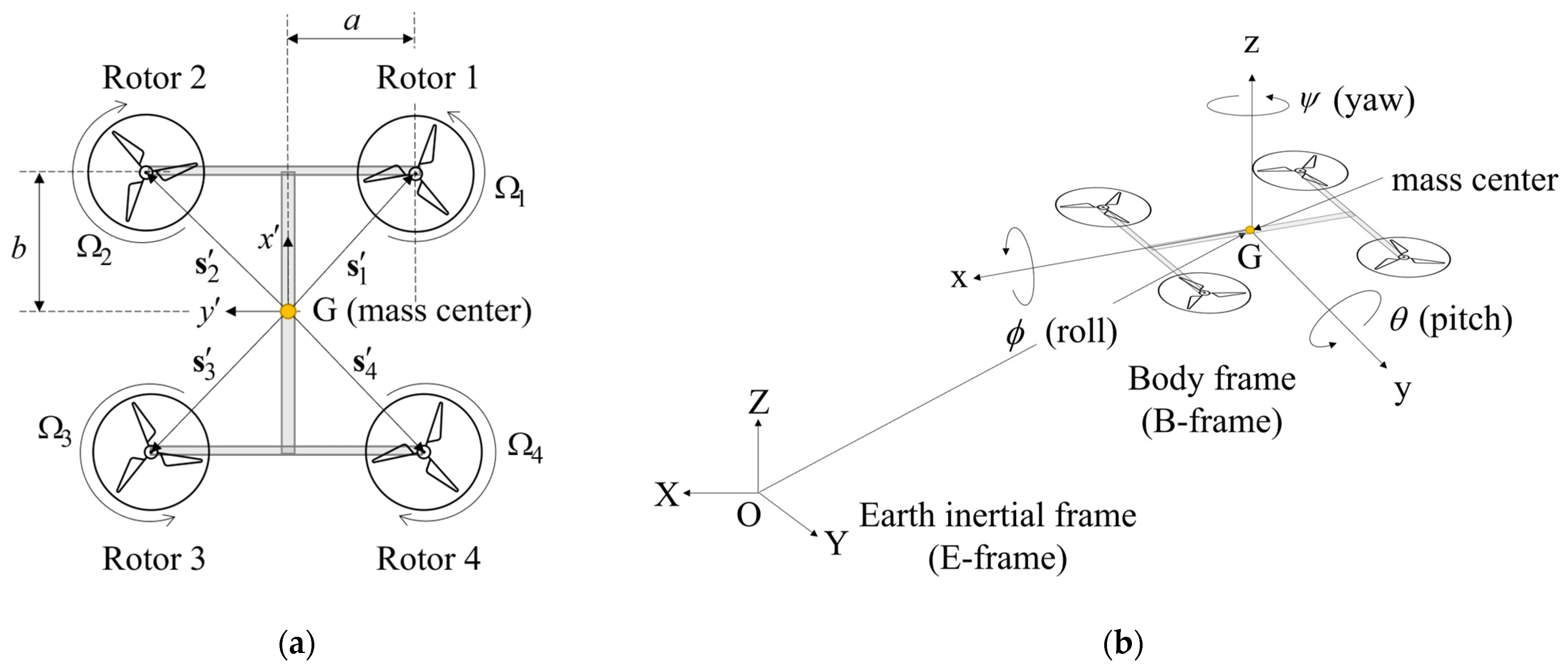
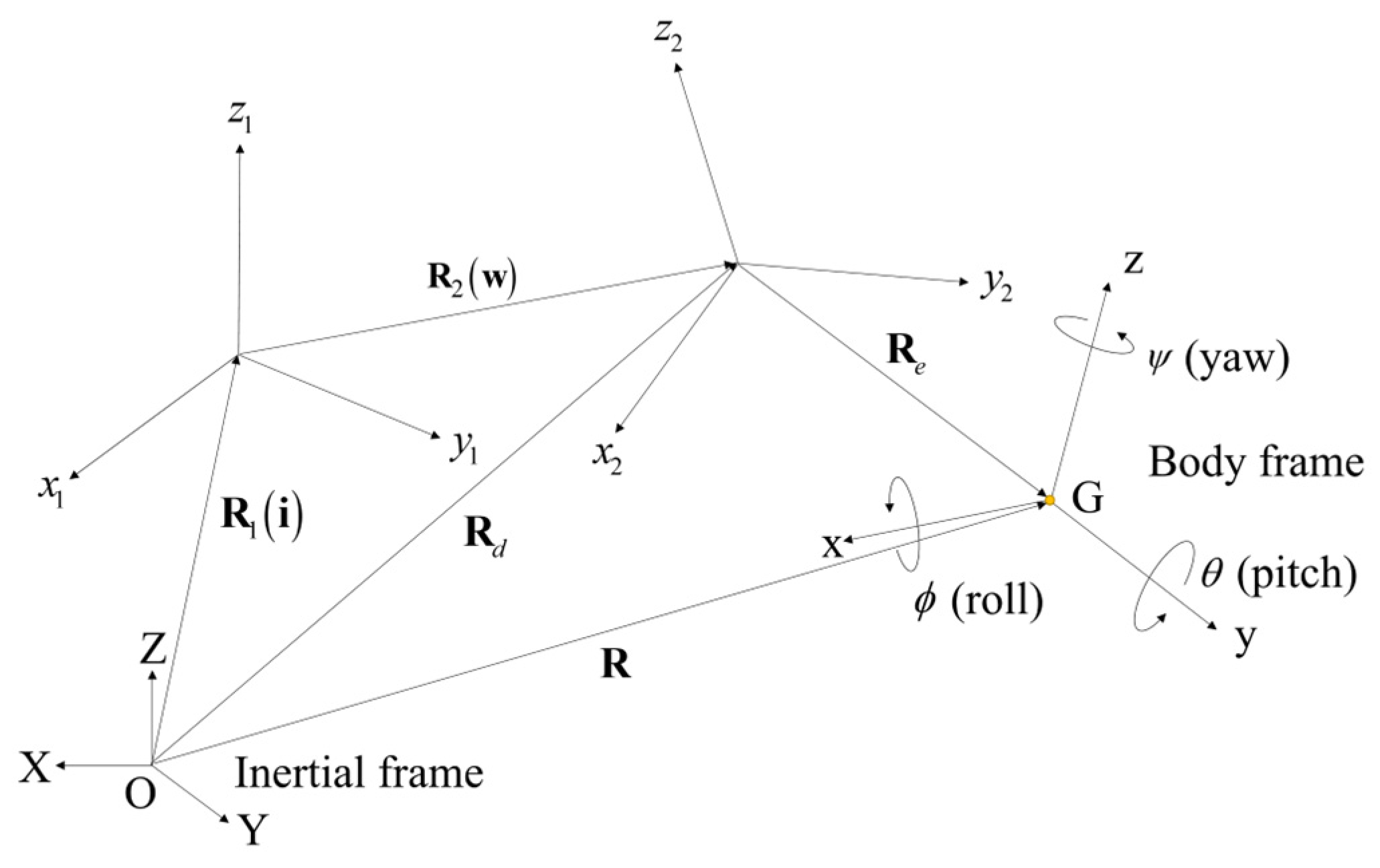
2. Theoretical Modeling
2.1. Dynamics
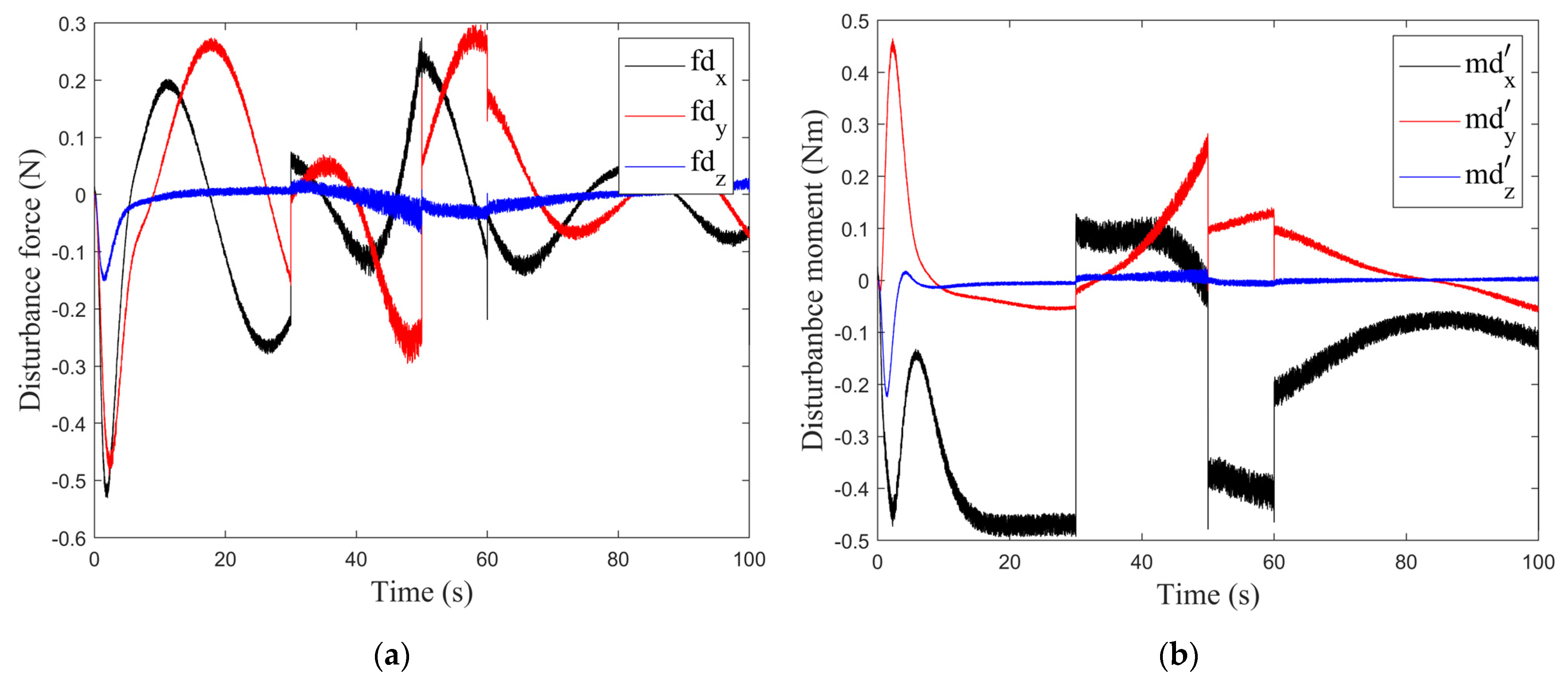
2.2. Wind Modeling
3. Controller Design
- -
- The magnitude of the quadrotor velocity does not exceed the actuator speed constraint:
- -
- The magnitude of the wind velocity does not exceed the actuator speed constraint:
3.1. PD Controller
3.2. RSMC Position Controller
3.3. RSMC Attitude Controller
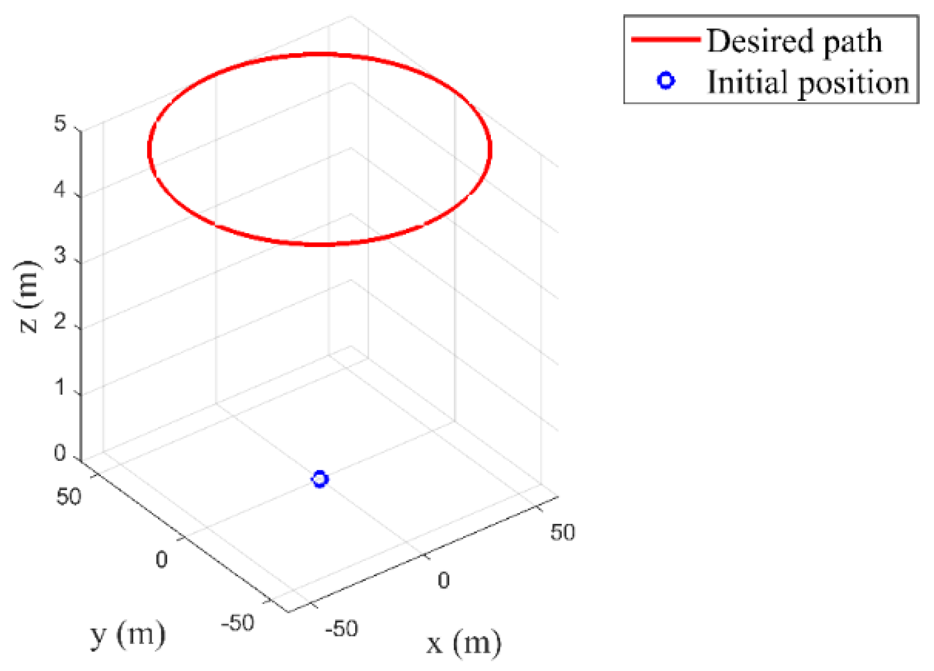
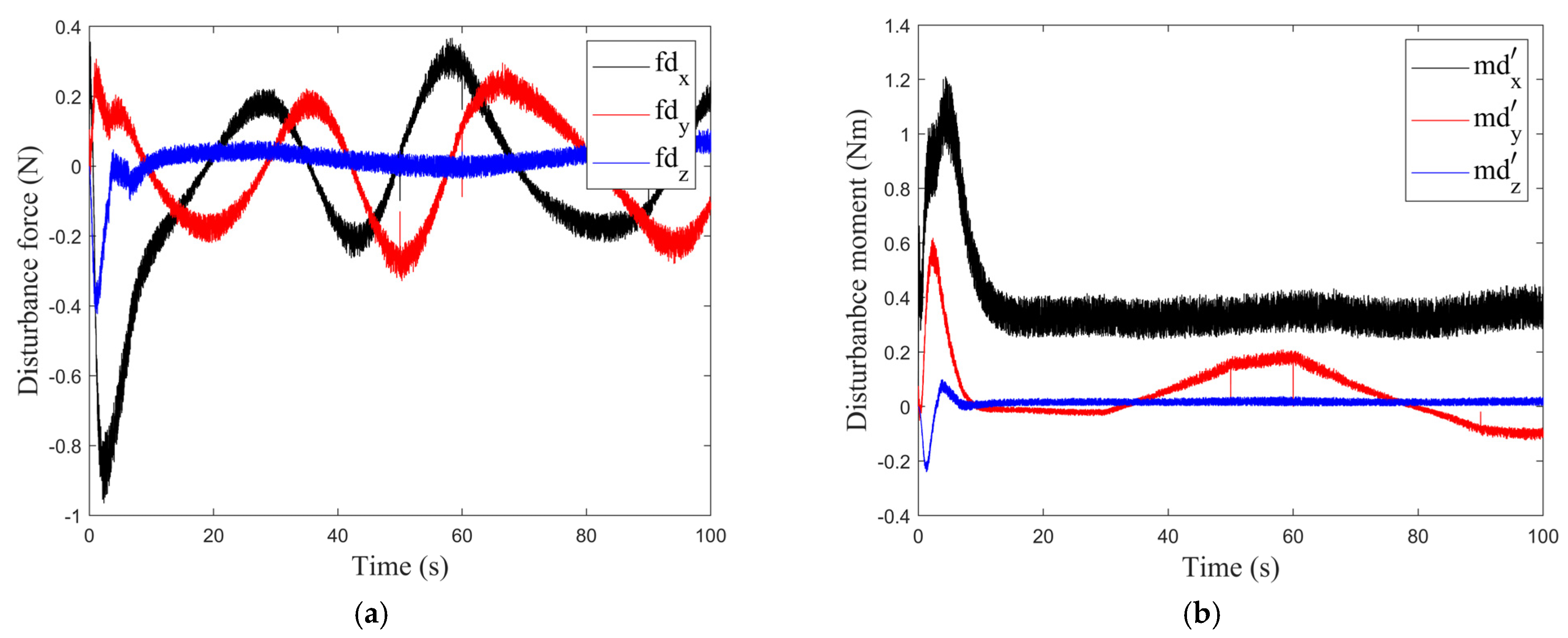
4. Results
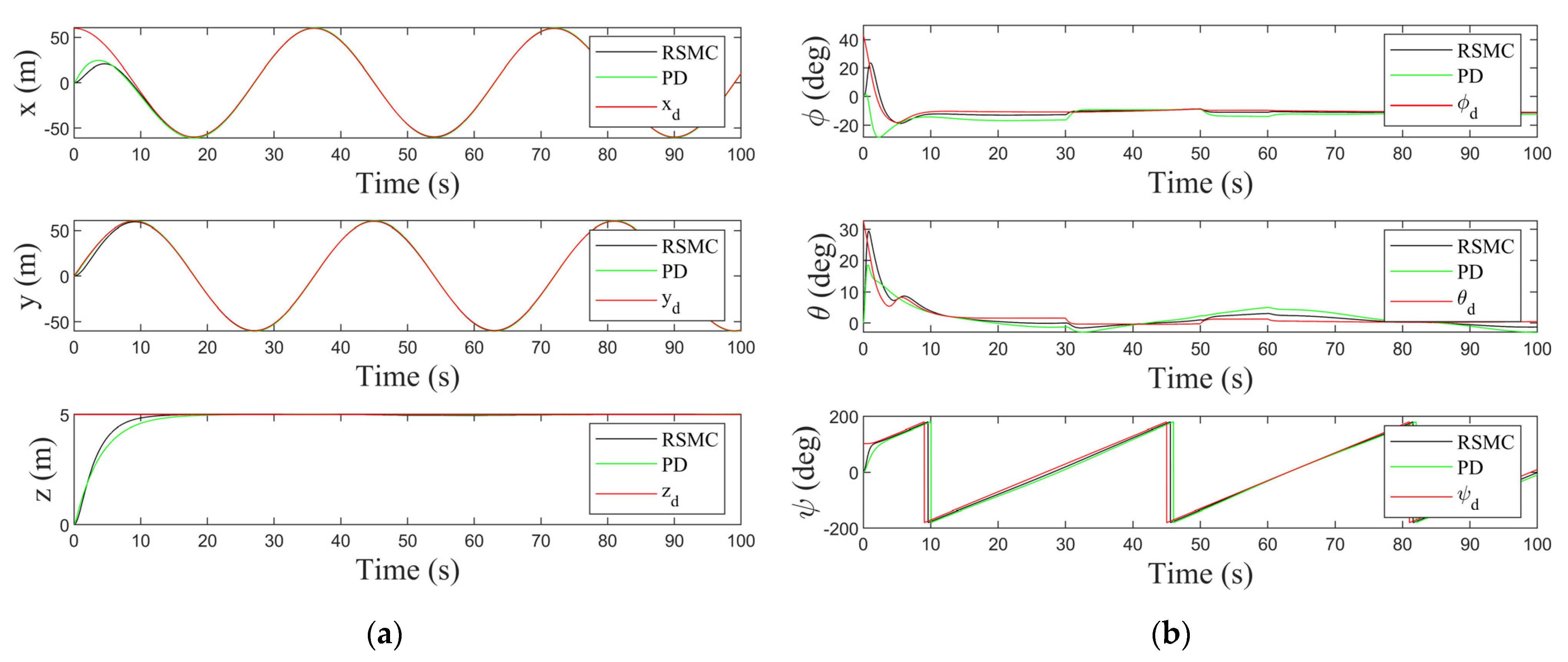
4.1. Scenario 1
4.2. Scenario 2
5. Discussions
6. Conclusions
Author Contributions
Funding
Data Availability Statement
Conflicts of Interest
References
- Cardona, G.A.; Ramirez-Rugeles, J.; Mojica-Nava, E.; Calderon, J.M. Visual victim detection and quadrotor-swarm coordination control in search and rescue environment. Int. J. Electr. Comput. Eng. 2021, 11, 2079. [Google Scholar] [CrossRef]
- Liu, Y.; Liu, S. Design and Implementation of Farmland Environment Monitoring System Based on Micro Quadrotor UAV. J. Phys. Conf. Ser. 2022, 2281, 012005. [Google Scholar] [CrossRef]
- Feng, L.; Katupitiya, J. Vector field based control of quadrotor uavs for wildfire boundary monitoring. J. Intell. Rob. Syst. 2022, 106, 27. [Google Scholar] [CrossRef]
- Thusoo, R.; Jain, S.; Bangia, S. Quadrotors in the Present Era: A Review. Inf. Technol. Ind. 2021, 9, 164–178. [Google Scholar]
- Lopez-Sanchez, I.; Moreno-Valenzuela, J. PID control of quadrotor UAVs: A survey. Annu. Rev. Control 2023, 56, 100900. [Google Scholar] [CrossRef]
- Ahmad, F.; Kumar, P.; Bhandari, A.; Patil, P.P. Simulation of the Quadcopter Dynamics with LQR based Control. Mater. Today Proc. 2020, 24, 326–332. [Google Scholar] [CrossRef]
- Sadiq, M.; Hayat, R.; Zeb, K.; Al-Durra, A.; Ullah, Z. Robust Feedback Linearization based Disturbance Observer Control of Quadrotor UAV. IEEE Access 2024, 12, 17966–17981. [Google Scholar] [CrossRef]
- Moeini, A.; Lynch, A.F.; Zhao, Q. A backstepping disturbance observer control for multirotor UAVs: Theory and experiment. Int. J. Control 2022, 95, 2364–2378. [Google Scholar] [CrossRef]
- Mofid, O.; Mobayen, S.; Zhang, C.; Esakki, B. Desired tracking of delayed quadrotor UAV under model uncertainty and wind disturbance using adaptive super-twisting terminal sliding mode control. ISA Trans. 2022, 123, 455–471. [Google Scholar] [CrossRef]
- Jiang, B.; Li, B.; Zhou, W.; Lo, L.-Y.; Chen, C.-K.; Wen, C.-Y. Neural network based model predictive control for a quadrotor UAV. Aerospace 2022, 9, 460. [Google Scholar] [CrossRef]
- Dooraki, A.R.; Lee, D.-J. An innovative bio-inspired flight controller for quad-rotor drones: Quad-rotor drone learning to fly using reinforcement learning. Rob. Auton. Syst. 2021, 135, 103671. [Google Scholar] [CrossRef]
- Abdelmaksoud, S.I.; Mailah, M.; Hing, T.H. Hybrid Fuzzy Logic Active Force Control for Trajectory Tracking of a Quadrotor System. In Proceedings of the International Conference on Emerging Technologies and Intelligent Systems 2022, Virtual, 2–3 September 2022; pp. 246–256. [Google Scholar]
- Shen, J.; Wang, B.; Chen, B.M.; Bu, R.; Jin, B. Review on wind resistance for quadrotor UAVs: Modeling and controller design. Unmanned Syst. 2023, 11, 5–15. [Google Scholar] [CrossRef]
- Xing, Z.; Zhang, Y.; Su, C.-Y. Active Wind Rejection Control for a Quadrotor UAV Against Unknown Winds. IEEE Trans. Aerosp. Electron. Syst. 2023, 59, 8956–8968. [Google Scholar] [CrossRef]
- Hassani, H.; Mansouri, A.; Ahaitouf, A. Backstepping-based supertwisting sliding mode attitude control for a quadrotor aircraft subjected to wind disturbances: Experimental validation. Int. J. Dyn. Control 2023, 11, 1285–1296. [Google Scholar] [CrossRef]
- Pliego-Jiménez, J. Quaternion-based adaptive control for trajectory tracking of quadrotor unmanned aerial vehicles. Int. J. Adapt. Control Signal Process. 2021, 35, 628–641. [Google Scholar] [CrossRef]
- Kang, J.-W.; Sadegh, N.; Urschel, C. Quaternion based nonlinear trajectory control of quadrotors with guaranteed stability. In Proceedings of the 2020 American Control Conference (ACC), Denver, CO, USA, 1–3 July 2020; pp. 3834–3839. [Google Scholar]
- Hassani, H.; Mansouri, A.; Ahaitouf, A. Robust autonomous flight for quadrotor UAV based on adaptive nonsingular fast terminal sliding mode control. Int. J. Dyn. Control 2021, 9, 619–635. [Google Scholar] [CrossRef]
- Ahmad, I.; Liaquat, M.; Malik, F.M.; Ullah, H.; Ali, U. Variants of the sliding mode control in presence of external disturbance for quadrotor. IEEE Access 2020, 8, 227810–227824. [Google Scholar] [CrossRef]
- Hassani, H.; Mansouri, A.; Ahaitouf, A. Model-Based Robust Tracking Attitude and Altitude Control of an Uncertain Quadrotor Under Disturbances. Int. J. Aeronaut. Space Sci. 2024, 25, 1464–1478. [Google Scholar] [CrossRef]
- Al-Dhaifallah, M.; Al-Qahtani, F.M.; Elferik, S.; Saif, A.-W.A. Quadrotor robust fractional-order sliding mode control in unmanned aerial vehicles for eliminating external disturbances. Aerospace 2023, 10, 665. [Google Scholar] [CrossRef]
- Phadke, A.; Medrano, F.A.; Chu, T.; Sekharan, C.N.; Starek, M.J. Modeling Wind and Obstacle Disturbances for Effective Performance Observations and Analysis of Resilience in UAV Swarms. Aerospace 2024, 11, 237. [Google Scholar] [CrossRef]
- Hellmann, G. Über die Bewegung der Luft in den Untersten Schichten der Atmosphäre; Kgl. Akademie der Wissenschaften [G.] Reimer: Berlin, Germany, 1914. [Google Scholar]
- MIL-F-8785C, Military Specification: Flying Qualities of Piloted Airplanes; United States Department of Defense: Washington, DC, USA, 1980.
- Howard, A. Experimental Characterization and Simulation of a Tethered Aerostat with Controllable Tail Fins; McGill University: Montreal, QC, Canada, 2008. [Google Scholar]
- Tran, N.K.; Bulka, E.; Nahon, M. Quadrotor control in a wind field. In Proceedings of the 2015 International Conference on Unmanned Aircraft Systems (ICUAS), Denver, CO, USA, 9–12 June 2015; pp. 320–328. [Google Scholar]
- Seo, D.; Kang, J. Collision-avoided tracking control of UAV using velocity-adaptive 3D local path planning. Int. J. Control Autom. Syst. 2023, 21, 231–243. [Google Scholar] [CrossRef]
- Hattenberger, G.; Bronz, M.; Condomines, J.-P. Evaluation of drag coefficient for a quadrotor model. Int. J. Micro Air Veh. 2023, 15, 17568293221148378. [Google Scholar] [CrossRef]
- Watkins, S.; Burry, J.; Mohamed, A.; Marino, M.; Prudden, S.; Fisher, A.; Kloet, N.; Jakobi, T.; Clothier, R. Ten questions concerning the use of drones in urban environments. Build. Environ. 2020, 167, 106458. [Google Scholar] [CrossRef]
- Zhou, X.; Yu, X.; Guo, K.; Zhou, S.; Guo, L.; Zhang, Y.; Peng, X. Safety flight control design of a quadrotor UAV with capability analysis. IEEE Trans. Cybern. 2021, 53, 1738–1751. [Google Scholar] [CrossRef]
- Melbourne, W. Criteria for environmental wind conditions. J. Wind Eng. Ind. Aerodyn. 1978, 3, 241–249. [Google Scholar] [CrossRef]
- Alaimo, A.; Artale, V.; Milazzo, C.L.R.; Ricciardello, A. PID controller applied to hexacopter flight. J. Intell. Rob. Syst. 2014, 73, 261–270. [Google Scholar] [CrossRef]
- Fresk, E.; Nikolakopoulos, G. Full quaternion based attitude control for a quadrotor. In Proceedings of the 2013 European Control Conference (ECC), Zurich, Switzerland, 17–19 July 2013; pp. 3864–3869. [Google Scholar]
- Sun, S.; Sijbers, L.; Wang, X.; de Visser, C. High-speed flight of quadrotor despite loss of single rotor. IEEE Rob. Autom. Lett. 2018, 3, 3201–3207. [Google Scholar] [CrossRef]


| Property | Value | Unit | |
|---|---|---|---|
| Geometrical parameters | 0.35 | m | |
| 0.55 | m | ||
| Total mass | 135 | kg | |
| Rotor mass | 15 | kg | |
| Thrust coefficient | 0.0047 | ||
| Torque coefficient | 3.93 × 10⁻⁴ | ||
| Air density | 1.225 | kg·m−3 | |
| Aerodynamic coefficients | 1.35 | ||
| 0.135 | |||
| Property | Value | |
|---|---|---|
| Position controller gain | 2 | |
| 8 | ||
| Attitude controller gain | 10 | |
| 5 | ||
| Property | Value | |
|---|---|---|
| Position controller gain | 1 | |
| 0.5 | ||
| 0.2 | ||
| 0.4 | ||
| Attitude controller gain | 2 | |
| 2 | ||
| 0.5 | ||
| 6 | ||
Disclaimer/Publisher’s Note: The statements, opinions and data contained in all publications are solely those of the individual author(s) and contributor(s) and not of MDPI and/or the editor(s). MDPI and/or the editor(s) disclaim responsibility for any injury to people or property resulting from any ideas, methods, instructions or products referred to in the content. |
© 2025 by the authors. Licensee MDPI, Basel, Switzerland. This article is an open access article distributed under the terms and conditions of the Creative Commons Attribution (CC BY) license (https://creativecommons.org/licenses/by/4.0/).
Share and Cite
Bae, J.-J.; Kang, J.-Y. Quaternion-Based Robust Sliding-Mode Controller for Quadrotor Operation Under Wind Disturbance. Aerospace 2025, 12, 93. https://doi.org/10.3390/aerospace12020093
Bae J-J, Kang J-Y. Quaternion-Based Robust Sliding-Mode Controller for Quadrotor Operation Under Wind Disturbance. Aerospace. 2025; 12(2):93. https://doi.org/10.3390/aerospace12020093
Chicago/Turabian StyleBae, Jung-Ju, and Jae-Young Kang. 2025. "Quaternion-Based Robust Sliding-Mode Controller for Quadrotor Operation Under Wind Disturbance" Aerospace 12, no. 2: 93. https://doi.org/10.3390/aerospace12020093
APA StyleBae, J.-J., & Kang, J.-Y. (2025). Quaternion-Based Robust Sliding-Mode Controller for Quadrotor Operation Under Wind Disturbance. Aerospace, 12(2), 93. https://doi.org/10.3390/aerospace12020093