Article

A Deployable Conical Log Spiral Antenna for Small Spacecraft: Electronic Design and Test

by
Lewis R. Williams
1,*,
Karina Vieira Hoel
2,
Lars Erling Bråten
1,2,
Arthur Romeijer
3,
Natanael Hjermann
2 and
Bendik Sagsveen
2
1
Department of Technology Systems, The University of Oslo, Gunnar Randersvei 19, 2007 Kjeller, Norway
2
Norwegian Defence Research Establishment, Instituttveien 20, 2007 Kjeller, Norway
3
Pulsaart by AGC Glass Europe, Rue Louis Blériot 12, 6041 Gosselies, Belgium
*
Author to whom correspondence should be addressed.
Aerospace 2025, 12(3), 218; https://doi.org/10.3390/aerospace12030218
Submission received: 20 January 2025 / Revised: 20 February 2025 / Accepted: 27 February 2025 / Published: 7 March 2025
(This article belongs to the Special Issue Small Satellite Missions)

Abstract

:
An ultra-high-frequency (UHF) deployable conical log spiral antenna’s design and experimental test results are presented. The antenna is a spring constructed from a carbon-fiber-infused epoxy matrix. The spring design simplified the spacecraft deployment mechanism, and the use of composite materials allowed for the integration of radiating elements into the spring structure. A Chebyshev transformer at the base of the antenna is used to match the incoming transmission line impedance to a 95 Ω coaxial cable. The 95 Ω coaxial, which is the balun and the radiating element, is embedded into the antenna structure. The antenna is fed at the cone’s base without requiring a ground plane whilst maintaining radiation in the cone’s apex-pointing direction. This facilitated an uncomplicated deployment mechanism. Prototypes have been manufactured for 500 to 1500 MHz designs. Antenna measurements show a realized gain of between approximately 3 to 6 dBi from 500 to 1500 MHz.

1. Introduction

UHF antennas with flight heritage on small satellites are mainly narrowband antenna types [1]. Dipoles, monopoles, Yagi-Uda or helical antennas [2,3,4,5,6] are those most commonly described in the literature. Broadband antennas at UHF have the potential to be larger than a small satellite, and may require a deployment mechanism [7], which increases system complexity and risk of failure. Broadband UHF antennas could expand small spacecraft capabilities [8]. Potential applications include communication services and Earth observations. A broadband UHF antenna combined with a flexible Software Defined Radio (SDR) payload may enable a single small satellite to implement several applications. Examples include communication with Internet of Things (IoT) sensors as well as radiometric measurements.
Numerous deployable UHF broadband antennas have been reported; however, to the authors knowledge, they do not have flight heritage at the time of writing. Two deployable Tightly Coupled Dipole Arrays (TCDAs) are proposed [9,10], offering dual polarization and ultra-wide bandwidths. The technology relies on low profile bending joints to achieve good packability of printed circuit board (PCB)-coupled dipoles. In [9], a one-dimensional foldable prototype array is demonstrated with an impedance bandwidth from 600 to 3200 MHz. To progress this design for flight, two-dimensional folding is envisaged for further size reduction.
A dual-band helix, a modified helix and a quadrifilar helix have been presented as broadband variants of the narrow band helical family. The dual-band helix [11] has six radiating arms cut as slots into a circular PCB. It is proposed to cover the Global Positioning System (GPS) L1 (1.575 GHz) and L2 (1.227 GHz) bands; however, there is no consideration for deployment. The modified helix [12] was developed for CubeSats to offer wideband UHF operation; however, the design requires a 1.2 m × 1.2 m ground plane. The quadrifilar helix [13] also developed for CubeSats obtains a 2:1 bandwidth by having the four spiral arms at different lengths. The antenna has high back lobe intensity, which the author expresses can be improved by tuning the size of the ground plane.
The Crossed Log Periodic Dipole Array (CLPDA) has been of interest for satellite applications due to its dual polarization and frequency-independent nature [14] since the 1960s, as demonstrated in [15], in which a conducting cone is proposed with the arm elements folding from a conical structure for space applications. More recent work [8] investigates bistable composite tape springs to deploy a CLPDA. The principle is only demonstrated for a single dipole and requires further development for a full prototype. The most recent example [16] uses tape springs for the antenna elements and a conductive zigzag foldable boom for the structure. The proposed deployment is achieved via an injection of compressed air to extend the boom.
A Conical Log Spiral Antenna (CLSA) offers similar performance as a CLPDA, whilst being structurally simpler [17]. Several papers outline CLSA spring designs [18,19,20] or a conductor printed on a foldable fiberglass substrate [21,22] and a highly truncated spiral [23]. Traditional CLSAs are fed at the cone’s apex and exhibit end fire radiation in the direction back toward the excitation point. This, combined with typically low levels of back lobe radiation [21], makes them well suited for spacecraft applications as the majority of the radiated signal will be in the antennas’ apex-pointing direction. Feeding the antenna at the apex requires a transmission line to be extended from the spacecraft to the antenna apex, increasing deployment complexity. A bottom-fed CLSA is proposed [19] which requires a ground plane to reflect the radiation away from the spacecraft. The size of the ground plane is ideally a disk with a diameter equal to or greater than the antenna height [19].
The discussed deployable CLSAs above either require a deployable transmission line from the spacecraft to the antenna apex, or a specifically sized ground plane to reflect the signals’ main lobe away from the spacecraft, if a bottom-fed arrangement is used. A deployable transmission line adds complexity to the deployment mechanism. A potential ground plane for a bottom-fed configuration may be larger than the available spacecraft surface; thus, it may need to be deployable, adding complexity. The aim of our design was to eliminate the need for both a deployable transmission line to the apex and a specifically sized ground plane.
This paper introduces a CLSA system design which allows a bottom-fed configuration whilst maintaining radiation in the apex-pointing direction without requiring a ground plane with a specific dimension to reflect the main lobe in the desired direction. This is achieved by means of a transmission line infinite balun in which a 95 Ω coaxial cable is the radiating element. The coaxial cable is embedded in the carbon spring structure. The design eliminates the need to extend a transmission line and a balun from the spacecraft to the antenna apex, which results in a practical and uncomplicated spring deployment design. The design offers reasonable realized gain over the desired bandwidth and circular polarization.
This paper is organized as follows. Section 2 outlines the antenna and feed network design. Section 3 discusses the experimental test results, and concluding remarks are outlined in Section 4.

2. Antenna and Feed Network Design

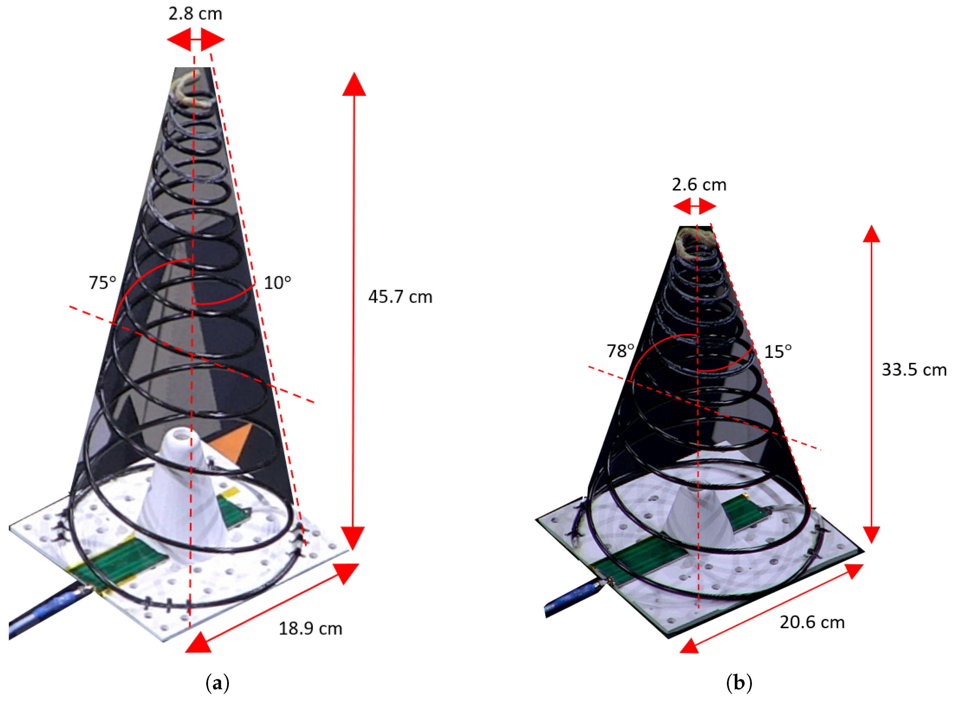
2.1. Conical Log Spiral Antenna Design

The design of a CLSA is well documented and was first detailed by Dyson in [24]. He also described a ’wire-only’ design, which has a constant diameter conductor, as a simplified CLSA [25,26,27]. We chose a constant-diameter conductor design, as opposed to a tapered conductor width, to simplify the structure and manufacturing. The consequence is a decrease in antenna performance compared to an optimal design. The wrap angle ( θ 0 ), cone angle ( α ), and desired bandwidth are required to dimension the antenna. We utilized Dyson’s design procedure which allows a slight reduction of the structure dimensions at the expense of distorting the radiated signal at the lowest design frequencies [24]. Lower cone angles provide a higher radiation front-to-back ratio and lower axial ratio [28]. Dyson also states that for a wire only design, if using a cone angle, α 10 , and wrap angle, θ 0 75 , one can expect minimal change to radiation patterns compared to a standard design [24].
We designed a wire-only CLSA with a cone angle, α = 10 , and wrap angle, θ 0 = 75 , denoted as the long design. We also built and tested the design detailed in our previous paper [20] with a cone angle, α = 15 , and wrap angle, θ 0 = 78 , denoted as the short design. The smaller cone angle design is expected to have better overall radio frequency (RF) performance, at the expense of being longer and possessing a higher spring stiffness.
Both antennas are designed for the frequency range 500 to 1500 MHz and are right-hand circularly polarized. The antenna structure consists of two identical conical spirals offset from each other by 180 , the dimensions of which can be seen in Figure 1. Both antennas are designed to be mounted onto a 20 cm × 20 cm square base plate.

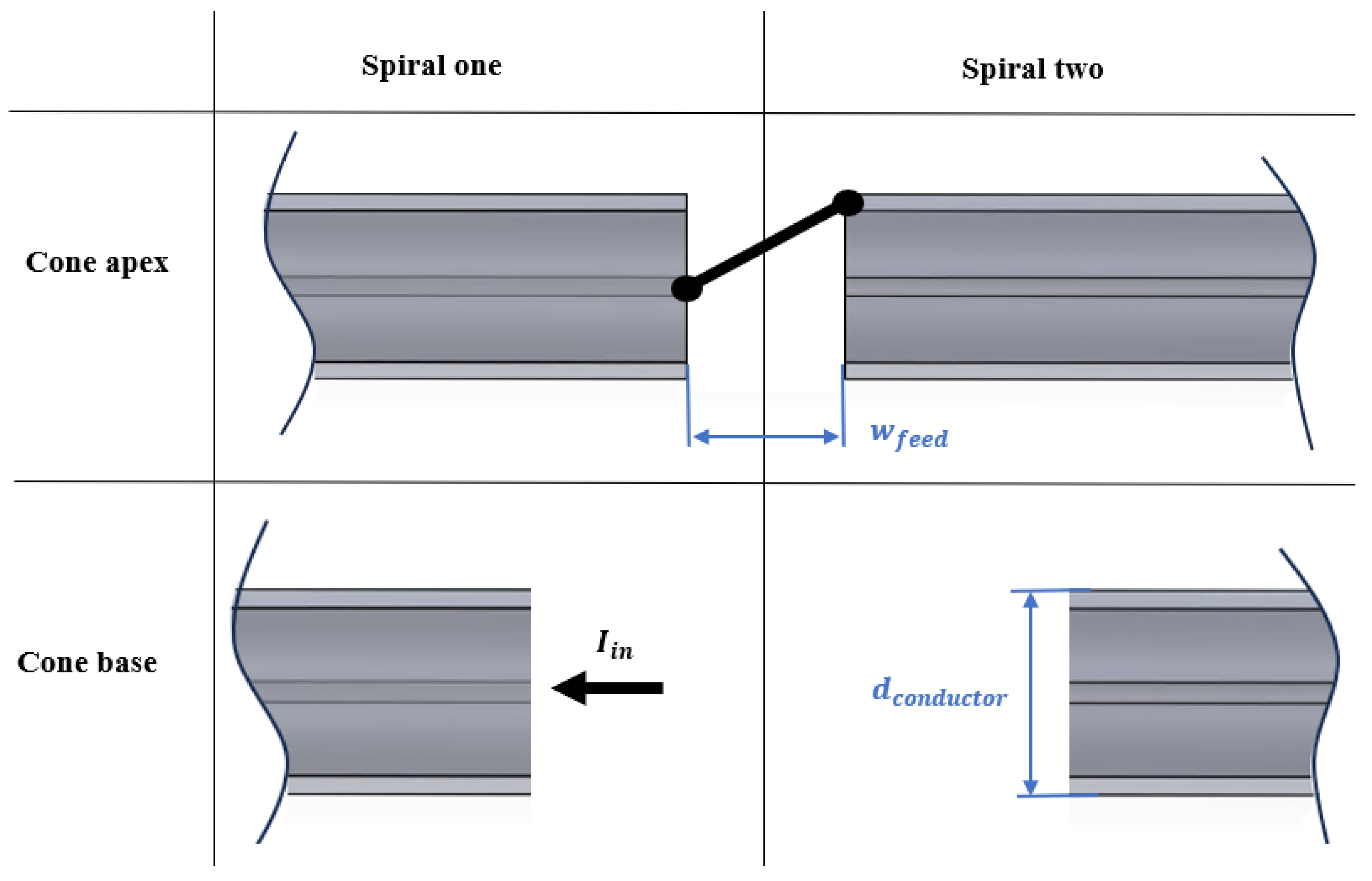
2.2. Impedance Network Design

The antennas’ characteristic impedance is mostly determined by the spiral conductor width [24]. Dyson characterized a traditional CLSA impedance in terms of the angular conductor width, which is a constant angle across the whole antenna due to the varying width of the spiral conductor. In our case, we have a constant conductor diameter. Defining the entire geometry of an antenna by angles is what defines a frequency-independent antenna [14]. Our antenna is not a true frequency-independent antenna and does not have a constant characteristic impedance over the entire bandwidth. However, from Dyson’s experimental results [24], we conclude that for a constant conductor CLSA with a fixed cone angle, the characteristic impedance, Z 0 , is approximately the maximum value minus some function of the physical conductor and cone diameters, d, within the maximum and minimum boundaries.
Z 0 320 f ( d c o n d u c t o r , d c o n e ) , Z 0 [ 80 , 320 ]
The maximum and minimum characteristic impedances found by Dyson were approximately 320 and 80 Ω , respectively [24]. The conductor diameter is the variable we can control to influence the impedance. The larger the conductor diameter, the lower the characteristic impedance [24].
Our design uses a Chebyshev transformer to transform from 50 to 95 Ω , followed by a 95 Ω coaxial cable infinite balun. A 95 Ω coaxial cable was chosen as it is within the impedance boundaries given by Dyson, has a larger diameter than 50 Ω cables, and is commercially available.
The infinite balun was first introduced by Dyson to feed an equiangular spiral antenna with a balun that could operate over a theoretically infinite impedance bandwidth of an infinitely sized frequency-independent antenna [29]. The balun is well documented in his subsequent works [25,26,27]. The current, I i n , is inserted into the coaxial cable of ‘spiral one’ at the cone’s base, as shown in Figure 2. At the apex of the cone, the coaxial cable of spiral one is truncated, and the inner conductor is extended to feed the shield of spiral two. For symmetry, the conductor of spiral two is an identical coaxial cable. The current at the truncation point of spiral one flows around the end of the shield and back down the spiral on the outside of the shield. At the base of spiral two, the coaxial cable is truncated and left as an open line. To provide a truly balanced feed, the current flowing from the apex must decay to negligible values before reaching the truncated base. The balancing property of this balun is reportedly improved by decreasing the width of the feeding gap, ( w f e e d ) (see Figure 2 [30,31]).
The designed Chebyshev transformer is a four-stage transformer designed for 500 to 1500 MHz. It has a total length of 163 mm and is printed on 1.524 mm thick Rogers 4350B substrate, as seen in Figure 3. The measured and simulated S11 and S12 parameters can be seen in Figure 4.
The Chebyshev transformer has a measured return loss (S11) below −15 dB across the designed bandwidth. The input losses (S12) are between 0.1 and 0.25 dB across the frequency range. This design was suitable for prototype testing, but its performance could be improved by utilizing a longer transformer with more stages.
For our designed deployable spacecraft antenna, the infinite balun is well suited since we can integrate the coaxial cable in the antenna structure and have an impedance transformer within the spacecraft. The feed point is technically located at the apex of the antenna where the two spirals meet; however, due to the integration of the cable into the structure, the feed network and radiator feed point are situated at the base of the antenna. In this design, a Huber+Suhner RG195 A/U cable with the outer jacket removed is used for the two spiral arms coaxial cables. RG195 was chosen for prototyping as it was readily available.
The RG195 coaxial cable jacket material is Perfluoroalkoxy (PFA), which is not highly resistant to radiation [32]. The jacket is removed for the antenna, with a small section of cable extending from the base to the Chebyshev transformer where the jacket is kept. Additionally, the manufacturer specifies that the maximum operating frequency for RG195 is 1 GHz. The cut-off frequency due to the propagation of the dominant transverse electric mode (TE11) is 48 GHz calculated and 47 GHz simulated. Testing the cable by sweeping up to 6 GHz with a Vector Network Analyser (VNA) shows that it is capable of operating within our frequency range. The RG180 coaxial cable is, for all intents and purposes, identical to RG195, except it has a jacket of Fluorinated Ethylene Propylene (FEP), which is better suited to space environments [32]. RG180 has specified max operating and cut-off frequencies of 3 and 44 GHz, respectively. RG180 was not used due to the longer manufacturing time, although it is available commercially at a cost similar to that of RG195.

2.3. Antenna Structural Design

The antenna structure is a carbon fiber epoxy composite, which houses the radiator within it and functions as a spring. Figure 5 shows a cross-section cut of the antenna structure. The carbon fiber used is Dowaksa A38 3K-braided tube (Manufactured by Dowaksa, Yalova, Turkey) and the epoxy is SikaBiresin® CR80 with hardener CH80-2 (Manufactured by Sika Group, Zurich, Switzerland). More information regarding the mechanical design can be found in a companion paper, which focuses on the mechanical design, manufacturing and environmental testing of the antenna.
Figure 6a shows the electrical connection and the feeding gap, which we made as small as practically possible (<1 mm). The solder point is reinforced with Kevlar-braided tubing and epoxy, as seen in Figure 6b. Kevlar was used in place of carbon fiber due to its lack of conductivity and the need to insulate the two spirals from each other. It provides the necessary stiffness to protect the soldering point. The base of spiral one (see Figure 2) is soldered directly onto the Chebyshev PCB to complete the assembly of the antenna. 3M Scotch-Weld DP2216 Epoxy Adhesive (Manufactured by 3M, Saint Paul, MN, USA) is applied to all soldering points for additional protection.

2.4. Spacecraft Attachment and Deployment

The antenna should be isolated from a metallic base plate by a non-conducting spacer. For prototyping, we used a base plate printed from polylactide (PLA). At the base of the spirals, the carbon composite structure is extended in a circular fashion, at approximately 1/4th of the cone’s base circumference, in order to provide a fixture point for the spirals to the base plate. The fixture configuration to the base plate can be changed depending on the location of the Chebyshev filter.
The tips of the antennas are too stiff to be completely compressed without damaging the structure, and, as such, the base plate incorporates a conical seat in the center, as seen on the base plates in Figure 1. The conical seats have a height of 10 and 5 cm and a base diameter of 8 and 6.5 cm, for the long and short designs, respectively. A smaller cone angle requires a larger conical seat due to the increased spring stiffness.
Irrespective of the chosen design, the spring is compressed for launch and connected to the base plate via a burn wire device which will hold the antenna. The antenna is released once in orbit, extending to its operational length.
The structure becomes shortened after it is compressed the first couple of times due to settling of the composite structure [33]. We made a scanned model of the structure using a 3D camera (Go!SCAN 3D camera by CREAFORM/AMATEK—Lévis, Canada) to quantify the deformation. The long antenna can be seen in a compressed state in Figure 7a, and the change in the long antenna’s geometry characterized with a 3D scan before and after 200 compressions can be seen in Figure 7b. The 3D scan result shows that the antenna has deformed, becoming shorter, from its original height of approximately 45.7 cm to 44.4 cm. The deformation is more pronounced towards the apex of the antenna, where the structure is stiffer.

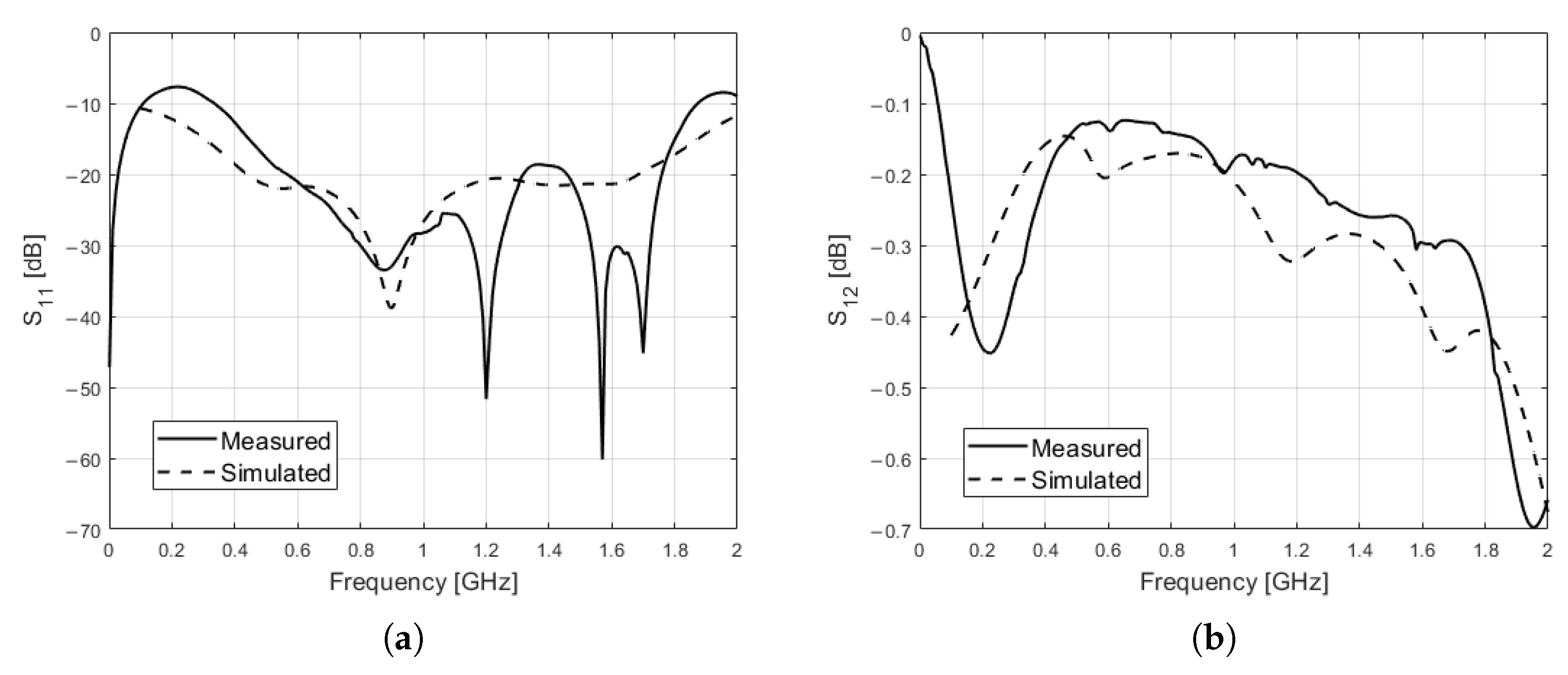
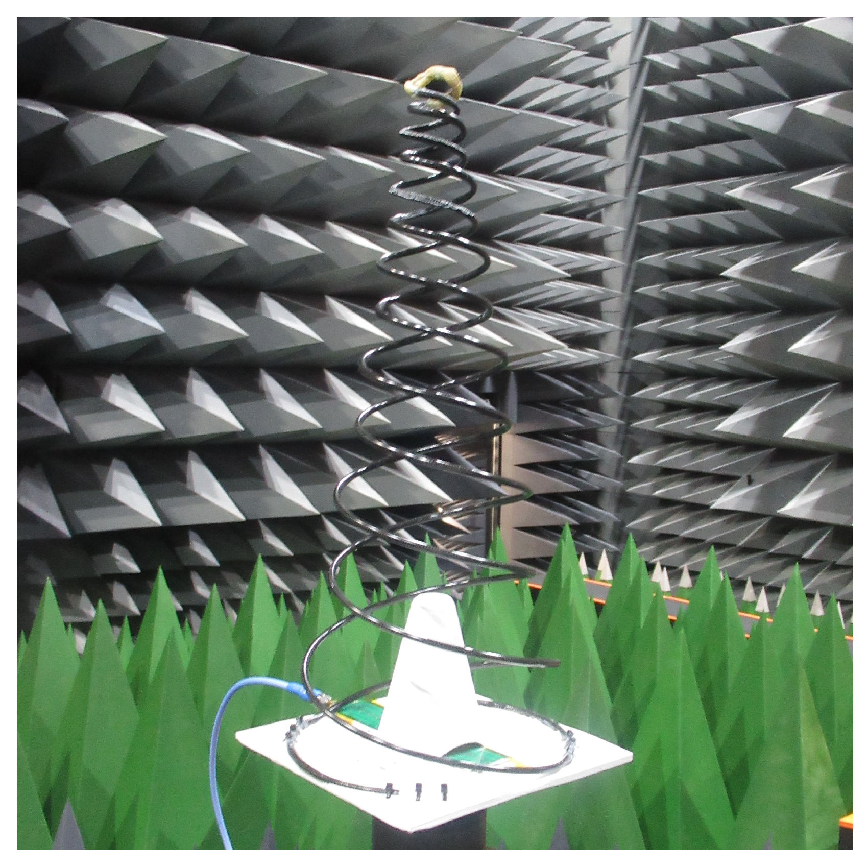
3. Antenna Measurements

Both antennas were tested to measure the reflection coefficient, radiation pattern, directivity, antenna total efficiency and axial ratio. The reflection coefficient was determined by measuring S11 at the input port of the Chebyshev transformer using a Rohde & Schwarz ZNLE6 VNA (Manufactured by Rohde & Schwarz, Munich, Germany). The other parameters were measured by Pulsaart by AGC Glass Europe in Belgium, on their multi-probe array (MPA) spherical near-field (SNF) range. Simulations were conducted using Ansys HFSS.
The MPA is divided into two semi-arches: one equipped with 22 dual-polarized probes at 5 spacing for the 64 to 400 MHz band and another with 111 dual-polarized probes at 1 spacing for the 0.4 to 6 GHz range. Its arch structure scans increase from 0 (zenith) to 110 ( 20 below the horizon). The anechoic chamber is lined with pyramidal absorbers of 48-inch and 60-inch sizes, minimizing reflections and external interference for accurate measurements down to 64 MHz. The test facility and results are certified to ISO 17025:2017 standard [34].
The two antennas under test (AUT) were precisely laser-aligned with the MPA arch structure before testing. Near-field measurements were conducted, with compressions performed between measurements while maintaining the antenna’s position and orientation unchanged. A near-field to far-field transformation was applied to the data, utilizing oversampling and modal filtering to mitigate residual reflections. Portions of the radiation pattern beyond the system’s elevation limits were extrapolated with zeros, which is acceptable given their minimal contribution to overall performance [35]. We used dual-ridged horns as reference antennas in the efficiency substitution technique [36], which enhanced the measurement accuracy due to their similar radiation characteristics to the AUTs. An AUT can be seen in the SNF chamber in Figure 8.
We tested the antennas before they were compressed and then compressed them a total of 10, 20, 50, 100 and 200 times. We also conducted a measurement at each step. Boresight directivity is shown in Figure 9 for the long antenna displaying the results from the antenna before and after 200 compressions. We can see that the compressions had a negligible effect on the antenna’s directivity despite the change in geometry. The same results were seen for the short antenna directivity.
Figure 10 shows the measured S11 for both antennas before and after 200 compressions. The change due to the compressions is negligible. We see that the short antenna has a slightly better reflection coefficient over the frequency range. We can also see that the data exhibit ripples, which are the result of impedance mismatch through the Chebyshev filter combined with the transmission line within our feeding spiral. The long antenna had 215 cm of transmission line, and the short design had 190 cm. Thus, any small mismatch through the transformer is seen as ripples due to multiple reflections. We observe that the S11 measurements in Figure 10 have the least ripples around 900 MHz, which is the same area with a sustained S11 below −30 dB without any sharp peaks on the measured S11 Chebyshev data (see Figure 4a).
From this point, we will only present the data for the antennas after 200 compressions as, in practice, any antenna that will be used will be exerted to numerous deployment test compressions.
The measured and simulated boresight directivity can be seen in Figure 11. The long antenna has a higher directivity than the short antenna at the majority of discrete frequencies, which is expected from Dyson’s analysis [24]. We can see that the long design also has less variation in directivity over the bandwidth, varying from approximately 8.5 to 7 dBi, whereas the short design varies from approximately 8.5 to 6 dBi. The simulated directivities are good approximations of the measured values.
Antenna total efficiency can be seen in Figure 12. The total efficiency includes the radiation efficiency and the impedance mismatch losses. We see more losses through the total efficiency data on the long antenna due to the extra coaxial cable loss and the slightly worse reflection coefficient, compared to the shorter antenna. The simulated total efficiencies are a good fit to the measured result.
The maximum and boresight realized gain for the long and short antennas are displayed in Figure 13. We see that the extra losses on the long design offset its improved directivity, and the performance of the short antenna is in line with the long antenna, when considering realized gain. We observed that the maximum gain is not necessarily at the boresight position. The slight skew in the radiation pattern is also visible in simulations. We can see the position of the offset in relation to boresight and a comparison to the simulated radiation patterns in the following E-plane radiation pattern plots at some selected frequencies. The radiation patterns are displayed for both antennas, measured and simulated at 500, 750, 1000, 1250 and 1500 MHz in Figure 14.
We can see from the radiation patterns that there is generally good agreement between the simulation and test for the long antenna. For the short antenna, the simulated radiation patterns are skewed, and a trend is also observed in the measured results, though to a lesser extent. For the measured results, the maximum radiation typically falls within ± 15 of the boresight position, and the offset between the maximum and boresight value is approximately 0.5 dB at some data points. The tilt in the radiation pattern is caused by either a construction error (non symmetrical spirals) or an imbalanced feed [24]. In the case of the long antenna, we do not see a tilt in the simulations. Moreover, in general, the max radiation is at boresight with the exception of some minor discrepancies. We conclude that the long antenna is properly balanced and is constructed correctly. For the short antenna, we observe a tilt in the simulated and measured patterns. As the simulation results are tilted, we can conclude that it is due to a slight unbalance in the feed. The infinite balun is truly balanced when the currents in the spirals are decayed to negligible levels before reaching the truncated base of the cone [24]. The shorter structure of the short antenna is thus not sufficient for the necessary decay, resulting in a slightly unbalanced feed and tilted pattern.
An unbalance in the feed is due to residual current reaching the truncated open-line spiral base and being reflected with an opposite phase back along the antenna spiral [37]. The rate of surface current decay is dependent on the radiation and resistive losses, the size of the radiating active region, and the tightness of the spirals [38,39]. It is worth noting that in the presented designs, we have reduced the size of the active regions to reduce the antenna structure’s overall size. The theoretical calculation of the surface current decay for spiral antennas is non-trivial [38,40,41]. However, the assessment of the surface current can be carried out with software such as HFSS (Version 2022 R2) during the design stage. In order to reduce residual surface currents at the base of the antenna, resistive loading can be applied to dissipate currents before the truncation point [42].
Due to the SNF range, we did not measure the back lobes. The simulated back lobes provide an estimation of the back lobe levels, and the simulated front-to-back ratio can be seen in Figure 15. The simulated results are for the antenna in free space, without the presence of a satellite body beneath the antenna. Low back lobe levels are desired to reduce interference. Front-to-back ratios are in the expected range when compared with previous research [28].
We did not include a metallic base plate during testing to simulate spacecraft surfaces. Although our design does not require a ground plane with specific dimensions to ensure functionality, the presence of a spacecraft structure beneath the antenna functions as a ground plane which may cause interference. Dyson reports that operation of a conical log spiral antenna over a ground plane had negligible effect on the antennas performance [25]. Nevertheless, we conducted a simulation of the long antenna placed over a ground plane. The ground plane was a 20 cm × 20 cm aluminum plate, which is the surface area occupied by the presented prototypes. The plate was placed 3 mm underneath the base of the antenna and was not in electrical contact with the spirals. Figure 16 shows a comparison of E-plane radiation patterns for the long antenna simulated over a ground plane, simulated in free space, and measured in free space.
As can be seen, the presence of the ground plane underneath the antenna generally had a negligible effect on the radiation patterns, which agrees with Dyson’s research [25]. At 500 MHz, we see some pattern distortion due to the presence of the ground plane. Slight pattern distortion at the lowest frequencies was also observed by Dyson, and it is reasonable considering that the active region at the lowest frequencies is in close proximity to the ground plane. Increasing the size of the ground plane, by placing the antenna on a larger spacecraft, may decrease the pattern interference due to reduced reflections from the plate’s edges and corners.
The measured axial ratio can be seen for both antennas in Figure 17. The axial ratios are presented at boresight and ± 30 of boresight. The axial ratio values presented at ± 30 of boresight are the average values of all phi angles at each frequency. We see that all the values are below 3 dB, which is typical for a circularly polarized antenna [43].

4. Conclusions

A carbon composite conical log spiral antenna for spacecraft applications is presented. The antenna is designed as a spring such that it can be deployed. The spring properties of the structure are provided by the carbon composite material. The radiator is a 95 Ω coaxial cable, which is also used as an infinite balun. This design allows the antenna to be fed at the base of the cone, avoiding the need for a cable to be extended to the apex, whilst maintaining end-fire radiation in the direction of the apex. The antenna does not require a ground plane. The antenna deployment is simplified by reducing the number of deployable components.
Prototypes were built and tested. We present two designs for comparison, a long and a short design. The designs are differentiated mainly by their cone angles, which are 10 and 15 , respectively. The tested antennas are both right-hand circularly polarised and have a realized gain between 3 and 6 dBi in the bandwidth of 500–1500 MHz. The long design exhibits better RF performance in terms of directivity and front-to-back ratio, at the expense of being physically larger and possessing a higher spring stiffness. The long design has more cable losses owing to a longer coaxial cable within the structure and a slightly worse reflection coefficient. In terms of realized gain, the long and short designs have similar performance across the designed bandwidth. There is flexibility in the antenna design procedure, which allows one to tune the performance and size for a specific application.
The antenna offers a broad bandwidth at UHF for small spacecrafts. It is scalable in frequency and can be utilized for various applications. When scaling the antenna, the lowest achievable frequency is dictated by the available spacecraft surface. When scaling up in frequency, practical limitations such as the tightness of the coils towards the apex need to be considered. With the proposed designs, it is estimated that up to 2 GHz would be practically implementable. However, utilizing a thinner, more flexible coaxial cable would enable higher-frequency designs.

5. Patents

A priority patent application was filed for this work by the University of Oslo in March 2025.

Author Contributions

Conceptualization, L.R.W., L.E.B. and B.S.; methodology, L.R.W., L.E.B., K.V.H., A.R., N.H. and B.S.; software, L.R.W., K.V.H., A.R. and N.H.; validation, L.R.W., L.E.B., K.V.H. and A.R.; formal analysis, L.R.W.; investigation, L.R.W., L.E.B., K.V.H., A.R, N.H. and B.S.; resources, L.R.W., L.E.B. and A.R.; data curation, L.R.W.; writing—original draft preparation, L.R.W.; writing—review and editing, L.R.W., L.E.B. and K.V.H.; visualization, L.R.W.; supervision, L.E.B., K.V.H. and B.S.; project administration, L.R.W.; funding acquisition, L.E.B. All authors have read and agreed to the published version of the manuscript.

Funding

This work was supported by the Research Council of Norway (Grant No. 309835), Centre for Space Sensors and Systems (CENSSS).

Data Availability Statement

The data presented in this study are available on request from the corresponding author due to privacy reasons.

Acknowledgments

Williams is pleased to acknowledge the contribution of the IMechE Whitworth Senior Scholarship Award in supporting his research.

Conflicts of Interest

The authors declare no conflicts of interest.

References

  1. Abulgasem, S.; Tubbal, F.; Raad, R.; Theoharis, P.I.; Lu, S.; Iranmanesh, S. Antenna Designs for CubeSats: A Review. IEEE Access 2021, 9, 45289–45324. [Google Scholar] [CrossRef]
  2. Saulius, R.; Laurynas, M.; Martynas, M.; Domantas, B. UHF/VHF monopole antenna array for cubesats. In Proceedings of the 40th ESA Antenna Workshop, Noordwijk, The Netherlands, 8–10 October 2019. [Google Scholar]
  3. Sureda, M.; Sobrino, M.; Millan, O.; Aguilella, A.; Solanellas, A.; Badia, M.; Munoz-Martin, J.F.; Fernandez, L.; Ruiz-De-Azua, J.A.; Camps, A. Design and Testing of a Helix Antenna Deployment System for a 1U CubeSat. IEEE Access 2021, 9, 66103–66114. [Google Scholar] [CrossRef]
  4. Huang, T.; Reveles, J.R.; Gurusamy, V.; Harrington, Q.; Fraux, V. An Innovative Deployable VHF/UHF Helical Antenna for Nanosatellites. In Proceedings of the 13th European Conference on Antennas and Propagation (EuCAP), Krakow, Poland, 31 March–5 April 2019; pp. 1–4. [Google Scholar]
  5. Dufour, L.; Andrade, D.; Maghaldadze, N.; Datashvili, L. High Performance Deployable Helical Antenna. In Proceedings of the 40th ESA Antenna Workshop, Noordwijk, The Netherlands, 8–10 October 2019. [Google Scholar]
  6. Bradbury, L.M.; Diaconu, D.; Molgat Laurin, S.; Beattie, A.M.; Ma, C.; Spydevold, I.S.; Haugli, H.C.; Zee, R.E.; Harr, J.; Udnæs, F. NorSat-2: Enabling advanced maritime communication with VDES. Acta Astronaut. 2019, 156, 44–50. [Google Scholar] [CrossRef]
  7. Costantine, J.; Tawk, Y.; Ayoub, F.; Christodoulou, C.G.; Olson, G.; Pellegrino, S. UHF deployable antenna structures for CubeSats. In Proceedings of the 2014 United States National Committee of URSI National Radio Science Meeting (USNC-URSI NRSM), Boulder, CO, USA, 8–11 January 2014; p. 1. [Google Scholar]
  8. Costantine, J.; Tawk, Y.; Christodoulou, C.G.; Banik, J.; Lane, S. CubeSat Deployable Antenna Using Bistable Composite Tape-Springs. IEEE Antennas Wirel. Propag. Lett. 2012, 11, 285–288. [Google Scholar] [CrossRef]
  9. Islam, M.R.; Carvalho, M.; Venkatakrishnan, S.B.; Volakis, J.L. Packable and Readily Deployable Tightly Coupled Dipole Array (TCDA) With Integrated Planar Balun. IEEE Open J. Antennas Propag. 2022, 3, 1206–1217. [Google Scholar] [CrossRef]
  10. Manohar, V.; Bhardwaj, S.; Venkatakrishnan, S.B.; Volakis, J.L. VHF/UHF Ultrawideband Tightly Coupled Dipole Array for CubeSats. IEEE Open J. Antennas Propag. 2021, 2, 702–708. [Google Scholar] [CrossRef]
  11. Yang, Y.H.; Guo, J.L.; Sun, B.H.; Huang, Y.H. Dual-Band Slot Helix Antenna for Global Positioning Satellite Applications. IEEE Trans. Antennas Propag. 2016, 64, 5146–5152. [Google Scholar] [CrossRef]
  12. Costantine, J.; Tawk, Y.; Moth, S.; Christodoulou, C.G.; Barbin, S.E. A modified helical shaped deployable antenna for cubesats. In Proceedings of the 2012 IEEE-APS Topical Conference on Antennas and Propagation in Wireless Communications (APWC), Cape Town, South Africa, 2–7 September 2012; pp. 1114–1116. [Google Scholar]
  13. Costantine, J.; Tran, D.; Shiva, M.; Tawk, Y.; Christodoulou, C.G.; Barbin, S.E. A deployable quadrifilar helix antenna for CubeSat. In Proceedings of the 2012 IEEE International Symposium on Antennas and Propagation, Chicago, IL, USA, 8–13 July 2012; pp. 1–2. [Google Scholar]
  14. Balanis, C.A. Antenna Theory Analysis and Design, 4th ed.; John Wiley & Sons: Hoboken, NJ, USA, 2016. [Google Scholar]
  15. Wu, P.-R. A deployable cross LPD array on a conducting cone. IEEE Trans. Antennas Propag. 1969, 17, 428–435. [Google Scholar]
  16. Liu, A.; Lu, J. A UHF Deployable Log Periodic Dipole Antenna: Concept, Design, and Experiment. IEEE Trans. Antennas Propag. 2021, 69, 538–543. [Google Scholar] [CrossRef]
  17. Olson, G.; Pellegrino, S.; Costantine, J.; Banik, J. Structural Architectures for a Deployable Wideband UHF Antenna. In Proceedings of the 53rd AIAA/ASME/ASCE/AHS/ASC Structures, Structural Dynamics and Materials Conference 2012, Honolulu, Hawaii, 23–26 April 2012. [Google Scholar]
  18. Costantine, J.; Tawk, Y.; Ernest, A.; Christodoulou, C.G. Deployable antennas for CubeSat and space communications. In Proceedings of the 6th European Conference on Antennas and Propagation (EUCAP), Prague, Czech Republic, 26–30 March 2012; pp. 837–840. [Google Scholar]
  19. Ernest, A.J.; Tawk, Y.; Costantine, J.; Christodoulou, C.G. A Bottom Fed Deployable Conical Log Spiral Antenna Design for CubeSat. IEEE Trans. Antennas Propag. 2015, 63, 41–47. [Google Scholar] [CrossRef]
  20. Williams, L.R.; Hoel, K.V.; Bråten, L.E.; Sagsveen, B. Design and Test of a UHF Deployable Conical Log Spiral Antenna for Small Satellites. In Proceedings of the 18th European Conference on Antennas and Propagation (EuCAP), Glasgow, UK, 17–22 March 2024; pp. 1–5. [Google Scholar]
  21. Costantine, J.; Tawk, Y.; Maqueda, I.; Sakovsky, M.; Olson, G.; Pellegrino, S.; Christodoulou, C.G. UHF Deployable Helical Antennas for CubeSats. IEEE Trans. Antennas Propag. 2016, 64, 3752–3759. [Google Scholar] [CrossRef]
  22. Costantine, J.; Tawk, Y.; Christodoulou, C.G.; Maqueda, I.; Sakovsky, M.; Pellegrino, S. A new UHF deployable antenna for cubeSats. In Proceedings of the 2015 IEEE International Symposium on Antennas and Propagation & USNC/URSI National Radio Science Meeting, Vancouver, BC, Canada, 19–24 July 2015; pp. 1426–1427. [Google Scholar]
  23. Sydor, J. The highly shortened conical helix. In Proceedings of the 2nd IEEE International Conference on Universal Personal Communications, Ottawa, ON, Canada, 12–15 October 1993; Volume 2, pp. 914–918. [Google Scholar]
  24. Dyson, J. The characteristics and design of the conical log-spiral antenna. IEEE Trans. Antennas Propag. 1965, 13, 488–499. [Google Scholar] [CrossRef]
  25. Dyson, J.D. The unidirectional equiangular spiral antenna. IRE Trans. Antennas Propag. 1959, 7, 329–334. [Google Scholar] [CrossRef]
  26. Dyson, J. A survey of the very wide band and frequency independent antennas-1945 to the present. J. Res. Natl. Bur. Stand. Sect. D Radio Propag. 1962, 66D, 1–6. [Google Scholar] [CrossRef]
  27. Dyson, J.; Mayes, P. New circular-polarized frequency-independent antennas with conical beam or omnidirectional patterns. IRE Trans. Antennas Propag. 1961, 9, 334–342. [Google Scholar] [CrossRef]
  28. Zaghloul, A.I.; Anthony, T.K.; Coburn, W.O. A study on conical spiral antennas for UHF SATCOM terminals. In Proceedings of the 2012 IEEE International Symposium on Antennas and Propagation, Chicago, IL, USA, 8–14 July 2012; pp. 1–2. [Google Scholar]
  29. Dyson, J. The equiangular spiral antenna. IRE Trans. Antennas Propag. 1959, 7, 181–187. [Google Scholar] [CrossRef]
  30. McLean, J.; Sutton, R.; Foltz, H. Quantitative assessment of the operation of the infinite balun. In Proceedings of the 16th International Symposium on Antenna Technology and Applied Electromagnetics (ANTEM), Victoria, BC, Canada, 13–16 July 2014; pp. 1–2. [Google Scholar]
  31. McLean, J.; Sutton, R. The off-axis, time-domain response of conical log spiral antennas. In Proceedings of the 2012 Loughborough Antennas & Propagation Conference (LAPC), Loughborough, UK, 12–13 November 2012; pp. 1–4. [Google Scholar]
  32. Galante, A.; Galante, O.; Campos, L. Study on application of PTFE, FEP and PFA fluoropolymers on radiation dosimetry. Nucl. Instruments Methods Phys. Res. Sect. A Accel. Spectrometers Detect. Assoc. Equip. 2010, 619, 177–180. [Google Scholar] [CrossRef]
  33. Madrazo, C. Carbon Fiber Coil Spring Characterization and Manufacturing. Master’s Thesis, University of Nevada, Las Vegas, NV, USA, 2022. [Google Scholar]
  34. ISO 17025:2017; General Requirements for the Competence of Testing and Calibration Laboratories. International Organization for Standardization: Geneva, Switzerland, 2017.
  35. IEEE Std 1720-2012; IEEE Recommended Practice for Near-Field Antenna Measurements. The IEEE Standards Association Standards Board: Piscataway, NJ, USA, 2012; pp. 1–102.
  36. Foged, L.; Castañer, M. Modern Automotive Antenna Measurements; Artech House: Norwood, MA, USA, 2022. [Google Scholar]
  37. Kraus, J.D. Antennas, 2nd ed.; McGraw-Hill: New York, NY, USA, 1988. [Google Scholar]
  38. Rumsey, V. A solution to the equiangular spiral antenna problem. IRE Trans. Antennas Propag. 1959, 7, 117. [Google Scholar] [CrossRef]
  39. McFadden, M. Analysis of the Equiangular Spiral Antenna. Ph.D. Thesis, Georgia Institute of Technology, Atlanta, GA, USA, 2009. [Google Scholar]
  40. Yeh, Y.; Mei, K. Theory of conical equiangular-spiral antennas–Part I–Numerical technique. IEEE Trans. Antennas Propag. 1967, 15, 634–639. [Google Scholar] [CrossRef]
  41. Mast, E. A Theoretical Study of the Equiangular Spiral Antenna; Antenna Laboratory Technical Report 035; University of Illinois at Urbana-Champaign: Urbana, IL, USA, 1958. [Google Scholar]
  42. Milligan, T.A. Modern Antenna Design, 2nd ed.; John Wiley & Sons, Inc.: Hoboken, NJ, USA, 2005. [Google Scholar]
  43. Volakis, J.L. Antenna Engineering Handbook, 5th ed.; McGraw-Hill Education: New York, NY, USA, 2019. [Google Scholar]
Figure 1. Antenna dimensions and angles for 500 to 1500 MHz designs: (a) ’long’ design with α = 10 and (b) ’short’ design with α = 15 .
Aerospace 12 00218 g001
Figure 2. Infinite balun feed utilizing a coaxial cable conductor for CLSA.
Aerospace 12 00218 g002
Figure 3. Four-stage Chebyshev transformer design for 50 Ω to 95 Ω transformation from 500–1500 MHz. (a) Built prototype .(b) Transformer geometry.
Aerospace 12 00218 g003
Figure 4. (a) Chebyshev transformer S11, measured and simulated. (b) Chebyshev transformer S12, measured and simulated.
Aerospace 12 00218 g004
Figure 5. Cross-section cut of antenna structure showing the internal RG195 A/U coaxial cable with the outer jacket removed integrated within the carbon fiber epoxy composite spring.
Aerospace 12 00218 g005
Figure 6. (a) Two spiral arms soldered together at the apex of the cone and (b) attachment reinforced by Kevlar-braided tube.
Aerospace 12 00218 g006
Figure 7. (a) The long antenna ( α = 10 ) in compressed state; (b) 3D scan results showing geometry of long antenna before and after 200 compressions.
Aerospace 12 00218 g007
Figure 8. Antenna under test in the SNF range.
Aerospace 12 00218 g008
Figure 9. Measured boresight directivity for long antenna before and after 200 compressions.
Aerospace 12 00218 g009
Figure 10. Measured S11 for long and short antennas before and after 200 compressions.
Aerospace 12 00218 g010
Figure 11. Measured and simulated boresight directivities for long and short antennas.
Aerospace 12 00218 g011
Figure 12. Measured and simulated total antenna efficiency for long and short antennas.
Aerospace 12 00218 g012
Figure 13. Measured maximum and boresight realized gain for long and short antennas.
Aerospace 12 00218 g013
Figure 14. Measured and simulated directivity E-Plane radiation patterns for long and short antennas at (a) 500 MHz, (b) 750 MHz, (c) 1000 MHz, (d) 1250 MHz, (e) and 1500 MHz. (f) Plot legend.
Aerospace 12 00218 g014
Figure 15. Simulated free space front-to-back ratio for long and short antennas.
Aerospace 12 00218 g015
Figure 16. Measured and simulated directivity E-Plane radiation patterns for the long antenna in free space and over ground (a) 500 MHz, (b) 750 MHz, (c) 1000 MHz, (d) 1250 MHz, (e) and 1500 MHz. (f) Plot legend.
Aerospace 12 00218 g016aAerospace 12 00218 g016b
Figure 17. Measured axial ratio for long and short antennas at boresight and within ± 30 of boresight.
Aerospace 12 00218 g017
Disclaimer/Publisher’s Note: The statements, opinions and data contained in all publications are solely those of the individual author(s) and contributor(s) and not of MDPI and/or the editor(s). MDPI and/or the editor(s) disclaim responsibility for any injury to people or property resulting from any ideas, methods, instructions or products referred to in the content.

