Abstract
The aircraft landing gear system is vital in ensuring the aircraft’s functional completeness and operational safety. The mechanical structures of the landing gear must withstand significant operational forces, including repeated high-intensity impact loads, throughout their service life. At the same time, they must resist environmental degradation, such as corrosion, temperature fluctuations, and humidity, to ensure structural integrity and long-term reliability. Under this premise, investigating material-related mechanical failures in the landing gear is of great significance for preventing landing gear failures and ensuring aviation safety. Compared to failure investigations, structural health monitoring (SHM) plays a more active role in failure prevention for aircraft landing gears. SHM technologies identify the precursors of potential failures and continuously monitor the operational or health conditions of landing gear structures, which facilitates condition-based maintenance. This paper reviews various landing gear material-related failure investigations. The review suggests a significant portion of these failures can be attributed to material fatigue, which is either induced by abnormal high-stress concentration or corrosion. This paper also reviews a series of load monitoring-based landing gear SHM studies. It is revealed that weight and balance measurement, hard landing detection, and structure load monitoring are the most typical monitoring activities in landing gears. An analytical discussion is also presented on the correlation between reviewed landing gear failures and SHM activities, a comparison of sensors, and the potential shift in load-based landing gear SHM in response to the transition of landing gear design philosophy from safe life to damage tolerance.
1. Introduction
Modern aircraft exhibit unprecedented intricacy and exceptionally high levels of complexity. An aircraft’s proper operation depends on the coordinated functioning of various subsystems. Among all these subsystems, the landing gear system is crucial in ensuring the aircraft’s structural integrity and operational safety during take-off, landing, and other ground manoeuvres, such as taxing and steering. The primary function of the landing gear system is to support the aircraft during ground operations, encompassing take-off and landing phases. It is also responsible for retardation and absorbing the impact forces encountered during landing, ensuring the aircraft’s and its passengers’ safety and enhancing passenger comfort [1,2,3,4].
1.1. Significance of Landing Gear Failure Investigation
Aircraft are more prone to malfunctions during take-off and landing due to intense operational demands placed on the aircraft’s mechanical systems, which must function under high stress and frequent use during these phases [5,6]. For example, during the landing phase, the landing gear must withstand the high-impact load of the aircraft hitting the runway, which demands much more than supporting the aircraft’s entire weight. Additionally, these phases involve critical transitions in aerodynamic forces and require precise handling, increasing the susceptibility to mechanical and operational errors. According to Airbus’s statistics on commercial aviation accidents from 2003 to 2023, 74% of aeroplane accidents occurred during the take-off or landing phases [7]. Ensuring the proper functioning of the landing gear is therefore particularly critical, given its vital role during these operational phases.
Among all failures or malfunctions in an aircraft system, there are three major categories: engine or fuel system-related failures, flight control-related failures, and landing gear failures [8]. Of all aircraft technical parts, the engines and landing gears are the most likely to result in incidents caused by a component failure. It was reported that 43% of all component failures of aircraft involved landing gears, 32% of failures involved engines, and 25% involved other technical part (fuselage, wings, etc.) failures [9]. Based on a statistical analysis conducted by the National Transportation Safety Board (NTSB) of the USA, of the 370 reported commercial aircraft accidents with a system/component failure/malfunction (SCFM) from 1988 to 2003, 115 accidents were related to landing gears or hydraulic systems. More specifically, nearly half of the 115 accidents were caused by landing gear component failure [8].
The repeated high operational forces that landing gear endures during service, along with the harsh operational environment, impose significant stress and an increased risk of failure on landing gear materials [10,11,12,13,14]. Consequently, the aviation sector has invested substantial resources and efforts in analysing various failures related to landing gear materials. Such analytical studies are crucial for identifying the root causes of these failures and facilitating the development of targeted improvement measures to prevent their recurrence. This paper introduces and discusses various studies on landing gear mechanical failures, including failure modes, failure inspection methods, and failure cause analysis.
1.2. Structural Health Monitoring (SHM) in Aircraft Landing Gear
Investigation of failure incidents is essentially a reactive approach, typically employed after a failure has occurred, to analyse its causes. However, as industrial modernisation progresses, there has been an increasing focus on enhancing the safety of systems or structures and reducing maintenance costs. Over the past few decades, researchers and engineers have dedicated efforts to developing proactive methods for monitoring the health status of systems and structures within their respective domains. These approaches enable the real-time and continuous surveillance of a structure’s condition, detecting early abnormal signals related to structural failure or degradation. By identifying these anomalies, interventions can be applied promptly to prevent the structure from failing. This proactive monitoring strategy aims to shift the focus from post-failure analysis and preventive maintenance to predictive maintenance, thereby enhancing the safety and longevity of critical assets and infrastructures. These monitoring methods are collectively referred to as SHM [15,16,17,18].
Unlike the damage-tolerance design methodology used for airframes, landing gear systems typically follow a safe-life design strategy. The damage-tolerance strategy allows for a certain level of damage development (such as crack propagation) as long as the resulting stress is still below the fatigue strength while the safe-life strategy aims to achieve a desired service life without any damage initiation and development, which can lead to structural failures [19,20,21,22,23]. Components in landing gears are subjected to high stress and very small windows for damage detection. Hence, the safe-life design principle can minimise the risk of sudden structure failure associated with undetected fatigue cracking or other damages. In addition, this design can simplify the landing gear maintenance and inspection processes since the components are expected to be damage-free throughout their designed service life. Thus, sophisticated and frequent inspections and maintenance are unnecessary, and components are replaced when approaching the end of their designed life span.
While the safe-life design philosophy for aircraft landing gears prioritises safety, it comes with two major disadvantages. The first one is overdesign. Safe life is a conservative design strategy that requires components to operate under stresses much lower than their fatigue stress, and hence these components are often heavier than necessary to ensure they do not fail within their designed lifespan. This can lead to increased material use and weight, negatively impacting fuel efficiency, emissions, and the overall performance of aircraft. The second disadvantage is the potential waste of resources. This type of design does not account for the actual condition of components, as it strictly follows a pre-set lifespan based on material properties. Components may still have a remaining useful life when they reach their predetermined lifespan limit, leading to potentially unnecessary replacements. This can result in higher maintenance and operational costs, as components are unused to their full potential. This inefficiency in resource utilisation negatively impacts both economic and environmental sustainability. Under this premise, performing SHM in aircraft landing gear components under various operational conditions and predicting their actual remaining useful life (RUL) based on collected data is highly desirable in the life-cycle engineering and management of landing gear systems [24]. Accurately assessing the RUL of structures is crucial for implementing condition-based maintenance (CBM) as it allows for maintenance to be performed precisely when it is needed, based on the future actual condition of the structures rather than on predetermined schedules [25,26,27,28,29]. This approach prevents unnecessary maintenance and thus reduces associated costs. Additionally, well-designed SHM approaches can detect early signs of malfunctions or failures in landing gear systems, allowing for preventative maintenance before actual failures occur. Furthermore, by analysing the collected data from different parts of landing gears, valuable insights into the design improvement can be obtained, which can potentially alter the current state of overdesign in landing gear and facilitate further weight reduction in landing gear systems [30].
With rapid development in sensing technology, wireless communication, and data processing capabilities over the past two decades, SHM technology has been significantly promoted in the aviation industry [31,32,33,34]. This is especially true for high-value, safety-critical aircraft structures like landing gear systems. Various sensors, such as temperature sensors, pressure sensors, strain gauges, accelerometers, and optical fibre sensors, are employed to continuously monitor their performance and conditions, aiming to prevent failures and extend their operational lifespan. The application of SHM technologies facilitates the prediction of the RUL of components, allowing for timely maintenance actions before catastrophic failures occur. Consequently, SHM not only enhances the safety and reliability of aircraft but also optimises maintenance schedules and associated costs. This paper primarily reviews a selection of representative studies concerning the application of load monitoring-based SHM technologies to aircraft landing gear. Given that landing gear operates under repeated high loads throughout its service life, monitoring load variations is critical for detecting load abnormalities that may lead to structural failures. In addition, continuously recorded load data can be further leveraged to gain valuable insights into structural health conditions. Therefore, this review focuses specifically on load monitoring-based SHM to provide a more in-depth analysis of this targeted approach. Critical monitoring activities, monitored parameters, and applied sensors are systematically elaborated in this paper.
In summary, this paper reviews both material-related failure investigations and load monitoring-based SHM studies in aircraft landing gear. In Section 2, a series of landing gear failure cases and failure analyses are reviewed and presented, while Section 3 elaborates on the review of typical SHM activities and applied sensors in landing gear systems.
2. Material-Related Failures and Failure Cause Analysis for Aircraft Landing Gear
This section reviews various material-related mechanical failure investigations associated with different types of aircraft landing gear. A detailed description of the failure, the failure cause analysis procedures, and the analysis results of each failure case are presented.
2.1. Failure Investigations Review
A nose landing-gear failure case was studied by Infante et al. [35], as depicted in Figure 1a. In this case, the landing gear fork made of 5000 series aluminium alloys was found to have failed during a landing. To investigate the causes of failure, apart from visual inspections (VIs), the researchers also carried out a material analysis using scanning electron microscopy (SEM). The inspection revealed that fatigue cracking appeared near the bolted holes of the gear fork, which was attributed to the cyclic stresses to which the fractured point was subjected.
Although a series of inspections have been performed on landing gears periodically during their service life, some unexpected failures can happen for different reasons. A landing gear strut bearing of a TB-20 Trinidad training aircraft fabricated from a 2000 series aluminium alloy failed due to cracks on the bearing [36]. A dye penetration inspection (DPI), a commonly used non-destructive testing (NDT) method, was performed to reveal the cracks. Additionally, an optical microscope (OM) and SEM enhanced with an energy-dispersive X-ray spectrometer (EDX) were employed for a more detailed inspection of the fracture surface. The inspection results showed that cracks were induced by corrosion and further developed under the joint effect of fatigue and corrosion. This type of cracking was called corrosion fatigue (CF), a common material failure mode in metallic structures under cyclic stresses and corrosive environments [37,38].
Another failure investigation associated with a piston rod end of a hydraulic actuating cylinder was conducted by Asi and Yeşil [39]. The piston rod, made of SAE4340 alloy steel, was found to be broken after a landing. A systematic inspection was arranged to evaluate the failure and analyse its root causes. Visual inspections, mechanical tests such as tensile testing and hardness testing, chemical analysis, and microstructural examination were carried out, and the results indicated that the fracture was caused by fatigue cracking, which was initiated due to local stress concentration near the mechanically damaged zone.
The landing gear trunnion is a pivotal structural component that serves as the mounting and pivot point for the landing gear assembly in aircraft. In a study conducted by Infante et al. [40], two broken landing gear trunnions (see Figure 1b) made of aluminium alloy 7075 were systematically examined. Similar to other failure-related studies in this field, inspection techniques such as visual examination, chemical analysis, and microstructural inspection were performed to uncover the potential causes of the failures. In this study, the beach marks presented on the fracture surface were carefully examined since they contain clues of the loading history, which can be utilised to study the crack development processes. Upon thorough investigation, fatigue associated with abnormally high stress was determined to be responsible for these two failures.
Zucca et al. conducted a failure investigation of fractured hinges (see Figure 1c) of a main landing-gear door in a transport aircraft [41]. The landing gear door is designed to cover and protect the landing gear compartment when the gear is retracted during flight. The hinges on a landing gear door are structural components that allow the door to pivot or rotate, enabling it to open and close to cover the landing gear compartment. In this case, the hinges are made of aluminium alloy 7075. It was observed that the left door for the main landing gear had fallen off due to the fracture of both the front and rear hinges. A number of examinations, including a Leica M 205C microscope and SEM with EDX, were used to perform a microanalysis of the fractures. Hardness testing was also conducted in this study. The results revealed that fatigue cracks originating from pitting corrosion were the main reason for the failures. The study also proposed that a more robust NDT technique, such as eddy current inspection, could be adopted for the more reliable detection of fatigue cracks at early stages.
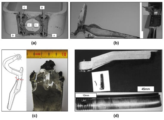
Figure 1.
(a) Fractured surface of the nose landing-gear fork [35]; (b) the failed trunnion and fractured surfaces [40]; (c) the fractured forward hinge [41]; (d) the linkage and clevis bolt fracture caused by abnormal shear stress [42].
Figure 1.
(a) Fractured surface of the nose landing-gear fork [35]; (b) the failed trunnion and fractured surfaces [40]; (c) the fractured forward hinge [41]; (d) the linkage and clevis bolt fracture caused by abnormal shear stress [42].

In another main landing-gear failure incident, a steel linkage and its corresponding clevis bolt experienced a fracture in a Cessna 402B aircraft (see Figure 1d) [42]. Microstructural inspection of the fractured area was performed using scanning electron microscopy following the initial optical examination to study the causes of failure. The study confirmed that the failure was caused by abnormal shear stress on the linkage, which was attributed to a hard landing due to human error.
A fracture of the outer cylinder lug (aluminium alloy-based) of the landing gear was reported in a study carried out by Azevedo et al. [43]. Figure 2a presents the fractured part along with a schematic diagram. The fractography inspection indicated that the ductile intergranular fracture originating from the pitting corrosion zone could be the reason for the failure. However, further analysis and communication with the manufacturer concluded that an unexpectedly high load during the landing should account for this incident.
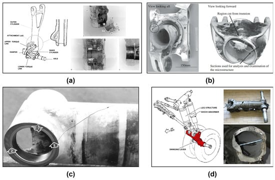
Figure 2.
(a) The outer cylinder lug fracture [43]; (b) the two parts of the fractured trunnion and the two fracture surfaces [44]; (c) the cracks and cracks origins (marked with arrows) on the landing gear truck beam [45]; (d) illustration and pictures of the fractured swinging lever [46].
Another landing gear failure (see Figure 2b) associated with the trunnion (made of ultra-high strength steel 4340 M) was reported to have occurred in a Boeing 747-300 aircraft [44]. After the failure, a metrological measurement was first performed on the fractured part. Following that, metallographic analysis, hardness testing and energy-dispersive X-ray analysis were carried out to analyse the material properties of the fractured area. Further fractography methods and microstructural examination were also involved in this investigation. The results indicated that fatigue cracking was determined to be the leading cause of this accident. Specifically, the observed fatigue cracks initiated due to intergranular attack at the bottom of some deep machining grooves, which are located at the root of the internal radius of the trunnion tube. These deep grooves were not expected to exist since they should have been shot-peened as required during manufacturing. In addition, the unexpected grooves were not detected during overhauls, which also indicates the need for a more sophisticated maintenance configuration.
A landing gear truck beam (made of SAE 4340 alloy steel) cracked (see Figure 2c) in a cargo aircraft was studied by Eliaz et al. [45]. Initially, a macroscopic examination was performed, and ratchet marks were identified on the fracture surface. Further metallographic and fractographic analyses, conducted using a stereomicroscope and SEM, indicated that stress corrosion cracking (SCC) occurred as a result of localised overheating. This overheating altered the material properties within the fractured zone and was caused by improper grinding during an overhaul. The root cause of this failure was improper maintenance.
Bagnoli et al. undertook a failure analysis on a main landing-gear collapse of a civil aircraft [46]. In this failure event, the swinging lever of the left-hand main landing gear (made of aluminium alloys) broke (see Figure 2d) during the take-off phase. Typical beach marks were observed by visual inspection, suggesting the occurrence of fatigue failure in this case. Subsequent investigations using field emission scanning electron microscopy (FESEM) along with energy-dispersive X-ray spectroscopy (EDX) and metallographic analysis confirmed that manufacturing deficiency led to an abnormal silicon concentration, which in turn triggered the fatigue failure.
The nose landing gear of an F-4 aircraft was reported to have failed due to a crack that was presented in the hydraulic actuator cylinder fabricated from aluminium alloy [47]. The crack was detected following an emergency landing, during which the landing gear tyre exploded, and an abnormal reading of the hydraulic meter was presented. The crack that resulted in the hydraulic pressure release was considered the primary cause of this incident. Researchers employed several inspection approaches to identify the causes of the crack, including chemical analysis, optical microscopy, and SEM. The examination implied that corrosion pits at the interior of the cylinder induced fatigue cracking, leading to the final crack. The root cause analysis of the corrosion initiation was not included in the study and requires further investigation.
In another recorded nose landing-gear trunnion fracture in a military transport aircraft, pitting corrosion, which facilitated fatigue crack growth, was confirmed as the cause for the gear collapse based on a series of examinations involving visual inspection, chemical analysis, optical microscope (OM), and SEM [48]. The researchers recommended that an NDT technique, such as high-quality dye penetration inspection, should be employed in periodical maintenance for early detection of minor cracks.
A lock link (made of 7175 aluminium alloy) fracture incident of the nose landing gear in a Boeing 767-200 aircraft was recorded and investigated by Ossa and Paniagua [49]. Fractographic analysis employing optical microscopy and SEM revealed evidence of fatigue cracks developing on the fracture surface. The metallographic analysis detected aligned precipitation of MgZn2 and FeAl3, which initiated fatigue cracks after cyclic loading, resulting in the final fracture. It was suggested that proper heat treatment on the material can effectively avoid the overgrowth of precipitates, thus preventing further fatigue cracking. A cantilever spring breakage in the landing gear of a fumigation aircraft was also studied in this research. The failure analysis demonstrated that surface corrosion, which was induced by a damaged protective coating, contributed to this failure.
2.2. Findings from the Review of Failure Investigations
Table 1 summarises the reviewed failure cases and offers their corresponding information, including failed structure material, aircraft and landing gear type, and applied failure analysis methods. This table aims to provide a concise and intuitive understanding of typical structure failures and their investigation approaches in landing gear systems.
Figure 3 presents an analysis of the failure causes of the reviewed failures in the form of a fishbone diagram. To investigate the potential correlation between structural failures and materials, the reviewed failures are classified into two categories based on the commonly used metallic materials in landing gears: aluminium alloys and high-strength steels.
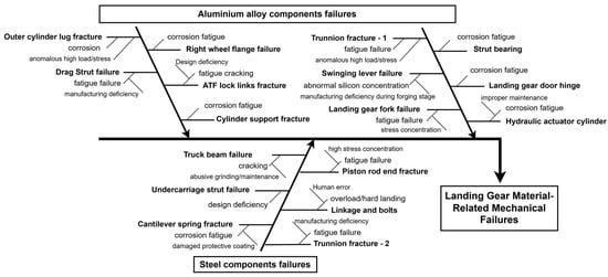
Figure 3.
Aircraft landing gear failures and cause analysis based on reviewed failure investigation.

Table 1.
Statistics of the reviewed landing gear failures.
Table 1.
Statistics of the reviewed landing gear failures.
| Failed Component | Reference | Failure Type | Material | Aircraft/Landing Gear Type | Failure Analysis Methods |
|---|---|---|---|---|---|
| Landing gear fork | [35] | Fracture | Aluminium alloy (series 5000) | Instruction aircraft/nose landing gear | VI *, SEM **, FEA *** |
| Strut bearing | [36] | Cracking | Aluminium alloy (AI-Cu) | TB-20 Trinidad training aircraft/main landing gear | VI, DPI 1, OM 2, SEM(EDX 3) |
| Hydraulic actuating cylinder piston rod end | [39] | Fracture | Steel (SAE4340) | Civil aircraft/nose landing gear | VI, Chemical Analysis, SEM(EDX), Hardness testing, Tensile testing, FEA |
| Trunnion | [40] | Fracture | Aluminium alloy (7075) | Military aircraft | VI, Chemical Analysis, OM, SEM |
| Landing gear door | [41] | Fracture | Aluminium alloy (7075) | Transport military aircraft/left main landing gear | VI, OM, SEM, Chemical Analysis, Hardness test, FEA |
| A linkage and corresponding clevis bolt | [42] | Fracture | Steel | Cessna 402B aircraft (civil)/main landing gear | VI, OM, Optical Macrography, SEM, Hardness testing |
| Outer cylinder lug | [43] | Fracture | Aluminium alloy (7000 series) | / | VI, SEM (EDX) |
| Trunnion | [44] | Fracture | Steel 4340M | Boeing 747-300/main landing gear | VI, Arc spectroscopy, Hardness testing, SEM (EDX), Magnetic Rubber, |
| Truck beam | [45] | Cracking | Steel (SAE 4340 alloy) | Cargo aircraft/main landing gear | VI, OM, SEM, Chemical Analysis |
| Swinging lever | [46] | Fracture | Aluminium alloy | ATR-42 aircraft (civil)/left main landing gear | VI, OM, Chemical Analysis, Hardness testing, SEM, EDX, FEA |
| Hydraulic actuator cylinder | [47] | Fracture | Aluminium alloy | F-4 aircraft/nose landing gear | VI, Chemical Analysis, OM, SEM |
| Trunnion | [48] | Fracture | Steel (micro-alloyed vanadium) | Military transport aircraft/nose landing gear | VI, Chemical Analysis, OM, SEM |
| Lock link | [49] | Fracture | Aluminium alloy (7175) | Boeing 767-200/nose landing gear | VI, OM, SEM, Chemical Analysis |
| Cantilever spring | [49] | Fracture | Steel (AISI 4340) | Fumigation aircraft | VI, SEM |
* VI = visual inspection; ** SEM = scanning electron microscopy; *** FEA = finite element analysis; 1 DPI = dye penetration inspection; 2 OM = optical microscope; 3 EDX = energy-dispersive X-ray spectrometer.
Upon extensive review of the mechanical structure failure investigations in landing gear systems, several key conclusions are drawn, as follows:
- The failure analysis of structural fracture normally follows a certain procedure (see Table 1). This typically involves a visual inspection to obtain a detailed description of the failure. This step is often followed by a microstructural examination (fractographic investigation) using an optical microscope (OM) or SEM to reveal more traces from fractured surfaces, which can provide indications of mechanisms of failure initiation and development. Mechanical tests and chemical analyses are usually carried out to study altered material properties associated with specific material failures, which also complements the accurate analysis of failure causes.
- Most mechanical structure fractures or cracking are associated with material fatigue (see Figure 3). Very few of them are induced by overload, which may be attributed to hard landing events. This finding has also been confirmed by previous research [50].
- Fatigue failures in landing gear structural components (commonly made of aluminium alloys or steel) often result from high-stress concentrations or material corrosion (see Figure 3). Abnormally high-stress concentration can initiate fatigue cracking and facilitate the fatigue process. Material corrosion can create pits or micro-cracks on the material surface, which can induce local stress concentration and initiate fatigue cracking. Furthermore, when fatigue cracks are exposed to a corrosive environment, the crack propagation can be accelerated by corrosion. The combined effects of corrosion and fatigue lead to rapid crack growth and eventual failure of the components. This type of fatigue is referred to as corrosion fatigue in material science. Based on this review, the failure types and causes do not exhibit any noticeable trend when differentiated by the two typical materials. However, previous research claimed that most corrosion fatigue failures are related to aluminium alloy structures in landing gears, while stress-related failures are more often observed in steel components [50]. This discrepancy may be due to limited reviewed failure cases, which may not be sufficient to reveal clear trends.
- Local stress concentrations always accompany the initiation and propagation of fatigue failures in metallic materials. This observation has already been confirmed in previous studies [51,52]. Within the aforementioned structural failure analysis of landing gears, FEA is frequently used to simulate the stress distributions in failed structures. By identifying potential stress concentration points through simulation and comparing these locations with the actual sites where fractures or cracking happen, the accuracy of failure cause analysis is further validated.
Currently, early detection of landing gear material-related failures is primarily conducted through scheduled inspections, using visual and NDT methods, often requiring the disassembly of components for off-site inspection. These inspection intervals are established according to the theoretical operating conditions and life cycles of structures and materials. However, the frequent exposure of landing gear to high stress associated with take-off and landing, varying weather conditions, temperature and humidity changes, and corrosive agents like runway deicers increase the uncertainty of failure occurrence. Consequently, some failures may initiate between scheduled inspections, leading to undiagnosed issues and eventual failure. Increasing the frequency of these inspections can mitigate such failures, but it also results in higher downtime of aircraft and associated maintenance costs, which is undesirable in the aviation industry. Moreover, many early-stage damage progresses do not show obvious signs, and current inspection methods may not effectively detect all potential precursors to these failures.
Therefore, developing a real-time SHM system for aircraft landing gear is highly desirable. By continuously monitoring critical indicators of operational health conditions of key structures during service, SHM systems can detect abnormal events that can lead to potential failure and early symptoms of failure onset, allowing for timely intervention to prevent ultimate failure. Implementing SHM systems can reduce reliance on periodic inspections, subsequently lowering maintenance costs. Additionally, SHM systems enable in-service monitoring without aircraft downtime, which can significantly improve operational efficiency and bring economic benefits to airlines. Though the employment of the SHM system can bring significant benefits to the maintenance of aircraft landing gear, it also arouses concerns. The introduction of the SHM system inevitably involves integrating additional sensors and data transmission equipment into the landing gear systems, which may raise concerns about the aircraft’s operational safety. Therefore, how to incorporate the SHM functions into the existing landing gear system without compromising operational safety requires special attention.
3. Load Monitoring-Based SHM Technologies for Aircraft Landing Gears
Due to the extremely high loads that landing gear systems are subjected to during service, along with the significant impact of these cyclic loads on materials, monitoring the loads experienced by landing gear structures is the dominant method for assessing their health condition. This article also provides an extensive review of previous load monitoring-based SHM studies in landing gear systems. The review reveals that a significant portion of these studies focuses on three critical monitoring activities: weight and balance measurement, hard landing detection, and structural load monitoring.
Weight and balance measurement plays a preventative role in the SHM of aircraft landing gears. It ensures that the aircraft’s weight and centre of gravity remain within the design specifications during operation. This is critical for preventing landing gears from experiencing excessive or unbalanced load during operations, which may lead to landing gear structural damage. Hard landing detection relies on dynamic load monitoring of the landing gears to determine whether the impact forces during landing fall within the design’s allowable safety limits. If these limits are exceeded, immediate inspection arrangements are required to assess potential structural damage from the hard landing. In contrast, structural load monitoring employs direct load measurement techniques to monitor the structural health of the aircraft. Traditional weight and balance assessments and hard landing detection typically use indirect load measurement methods, such as displacement sensors, pressure sensors, or accelerometers. These sensors measure relevant variables, which are then converted into load estimates. Compared to these indirect approaches, structural load monitoring focuses on measuring the local load conditions of any particular landing gear components using direct load measuring sensors such as strain gauges or fibre Bragg grating (FBG) sensors. By directly measuring and analysing loads on critical parts, it can detect anomalies such as unusual stress concentrations, which are often precursors to structural damage. Furthermore, the continuous collection of dynamic load data enables deeper analysis, such as evaluating the actual fatigue life of landing gear components. Notably, because direct load measurement is more straightforward than indirect load calculations and benefits from the precision and stability of advanced sensors like strain gauges and FBG sensors, some modern systems for weight and balance monitoring and hard landing detection have begun adopting direct load measurement techniques.
These SHM activities are crucial for ensuring the structural integrity of aircraft landing gear and significantly enhancing operational safety. Overall, the implementation of SHM systems for landing gear systems allows for the continuous monitoring of key indicators of anomalies, enabling condition-based maintenance and reducing the cost associated with over-maintenance. Based on this review, five types of commonly used sensors for these three SHM activities are described in Table 2 with working principles.
Table 2.
Applied sensors in the three key SHM activities.
Table 2.
Applied sensors in the three key SHM activities.
| Sensor Name | Working Principle |
|---|---|
| Pressure sensors | Pressure sensors are used to monitor the hydraulic or pneumatic pressure within the shock absorbers of an aircraft’s landing gear [19]. The principle behind this application is based on the correlation between the pressure within the shock absorbers and the load applied to them. By accurately measuring the pressure, the weight supported by each landing gear leg can be determined. The aggregate data from all landing gear legs provide a precise measurement of the aircraft’s overall weight and distribution. A hard landing typically generates a significant spike in pressure, which can be detected and recorded by the pressure sensors. The data collected can be analysed to assess the severity of the landing impact. If the pressure exceeds predefined thresholds, it indicates a hard landing event. |
| Displacement sensors | Displacement sensors (such as linear position sensors) are used to measure the stroke of the shock absorbers [53]. The displacement of the shock absorber is directly related to the load applied to the landing gear. By measuring the degree of compression, the displacement sensors provide data that can be used to calculate the weight supported by each landing gear leg. These displacement data, combined with the geometry of the landing gear and the known characteristics of the shock absorbers, allow for an accurate determination of the aircraft’s weight and balance. Similarly, hard landings cause rapid and significant compression of the shock absorbers, which can be precisely measured by the displacement sensors. |
| Accelerometers | Accelerometers are found to be used for both structural load monitoring and hard landing identification of landing gears [54]. In these cases, sensors are positioned to the selected load-bearing structures of landing gears through meticulous design, enabling the aimed functions. Following the law that the force applied to a structure is equal to the object’s mass multiplied by its acceleration, it is possible to calculate the load of specific structures based on acceleration measurements. Accelerometers detect hard landings by measuring the acceleration forces experienced during touchdown. These sensors operate on the principle of detecting changes in velocity over time, which can be translated into inertial forces. When the aircraft lands, accelerometers capture the dynamic forces in multiple directions, primarily focusing on the vertical axis. If the recorded acceleration exceeds predefined safety thresholds, it indicates a hard landing. |
| Strain gauges | Monitoring surface strain to determine the forces acting on the structure, which can then be used to calculate the corresponding loads. Strain gauges measure strain based on the change in electrical resistance of a conductor or semiconductor material bonded to the structure. When the material deforms under load, its electrical resistance changes proportionally, which can be measured and converted into strain data [55]. |
| FBG sensors | Monitoring surface strain to determine the forces acting on the structure, which can then be used to calculate the corresponding loads [56]. FBG sensors use optical fibres with a periodic variation in the refractive index. When the fibre experiences strain, the wavelength of the reflected light shifts, and this shift can be precisely measured to determine the amount of strain [57,58,59,60]. The obtained loads of structures can be further processed to achieve either weight and balance measurement or hard landing detection or load monitoring of specific structures. |
3.1. Weight and Balance Measurements
Weight and balance measurements are vital for maintaining proper aircraft performance and safety [61,62]. Incorrect weight and balance measurement can lead to severe operational issues, including inefficient fuel consumption and compromised flight stability. Monitoring these parameters ensures that the aircraft operates within its design limits, preventing potential abnormal structural stress and subsequent failures. Accurate weight and balance measurements help maintain the optimal centre of gravity, ensuring safe take-offs, landings, and overall flight operations. The weight-on-wheels (WOWs) measurement and centre of gravity (CG) calculation are two key monitoring activities included in the weight and balance measurement. The WOW measurement involves determining the aircraft’s total weight supported by the landing gear [63]. This measurement is crucial for confirming that the aircraft is within its weight limits for safe operation. Accurate WOW measurements ensure that the aircraft operates within its designed weight parameters, preventing potential overload and structural damage. CG is the point where the aircraft’s mass is balanced. Proper CG calculation is essential for flight stability and control [64]. An incorrect CG can result in poor handling characteristics, increased fuel consumption, and even risk of loss of control. Monitoring and adjusting the CG ensures that the aircraft maintains optimal performance and safety during all phases of flight.
One of the primary functions of the WOW system is to provide an indication or alert when the aircraft first makes ground contact. Traditional WOW systems use linear position sensors to measure shock absorber compression, indicating the initiation of the ground reaction of the landing gear. However, this method can only be effective when the impact load is high enough to trigger the shock strut displacement in millimetres. Thus, these systems have poor resolution, and their accuracy degrades over time due to friction in the landing gear’s moving parts. Jimenez et al. proposed a load pin-based WOW measurement approach, which detects ground contact by monitoring load at the critical nodes of landing gears using strain gauge-based load pins [65]. Since the detection of the landing load by the load pin occurs much earlier than the compression of the shock strut is perceived, aircraft braking systems are activated earlier, enabling landing on shorter runways. With real-time and high-resolution capabilities to measure loads, this new WOW system could optimise maintenance actions and damage control of landing gear components, providing valuable data to calculate fatigue damage for each landing cycle accurately. A direct load measurement method was proposed in a landing gear SHM research study by Forrest et al. [19]. The research was supported by Naval Air Systems Command (NAVAIR) and conducted by ES3. The advanced load pin, which was based on strain gauge technology, replaced the drag brace pin to monitor the node loads in this study. The collected load values were fused with data from the aircraft’s health and usage monitoring system (HUMS), coupled with dedicated algorithms, enabling aircraft actual weight and balance evaluation such as WOW measurement and CG calculation as well as abnormal load status warnings of hard landings. Additionally, the continuous monitoring of loads of critical structures or nodes facilitates the fatigue life assessment of the landing gear structures, which enables condition-based maintenance, reducing unnecessary maintenance and related costs.
A laboratory-based investigation of landing gear ground reaction measurement was conducted by Skorupka using two strain gauge-based direct force measurement methods and one indirect approach employing accelerometers [66]. The ground reaction measurement of the landing gear involves the use of sensors to monitor the forces exerted on the landing gear during ground contact. These data can be used to perform weight-on-wheels (WOWs) calculations and to detect hard landings by measuring the impact forces experienced during touchdown. In this study, one direct method achieved force measurement by installing strain gauges on the ground plate mounted under the landing gear, while the other method deployed strain gauges on the landing gear mounting nodes. The second direct method is capable of performing the real-time monitoring of stress applied to landing gears. The acceleration-based load monitoring requires a firm mounting of the sensors to the monitored structures because accelerometers are very sensitive to mounting errors, which can lead to incorrect measurement. Normally, the acceleration measurement is used together with direct force measurement for cross-verification purposes, which can minimise measurement errors. The dynamic drop test demonstrated that both the direct and indirect methods can achieve satisfactory accuracy and efficiency, with less than 5% error for direct approaches and 10% for indirect methods compared with each other. Notably, the usability of acceleration measurement data for load calculations relies on proper transducer installation and accurate estimation of environmental influences during testing. In contrast, direct force measurement is less affected by these factors due to lower sensitivity and predefined transducer placement based on landing gear design.
Another study of aircraft landing gears employed FBG sensors to detect strains in the key areas of a landing gear [67]. The study aimed to develop a new FBG-based weight and balance measurement system for aircraft landing gears to determine the actual weight and centre of gravity during taxiing. To identify the most critical locations where FBG sensors should be placed, FEA was carried out to simulate the actual loading conditions of the landing gear structures. Traditional strain gauges were also attached to the same areas to validate the proposed approach and obtain reference data. Figure 4a illustrates the deployment of FBG sensors in the tested landing gear. The results obtained from the two different methods showed good consistency, which verified the effectiveness of FBG sensors in load monitoring of landing gear structures. The study also revealed that FBG sensors installed on the wheel axle achieved the highest sensitivity. In addition, the study found that monitoring the load/strain along the horizontal axis of the main fitting can be an effective alternative to monitoring the wheel axle when FBG sensors cannot be installed on the wheel axle in some cases. The researchers emphasised the FBG sensors’ strengths, which include higher accuracy, longer stability, smaller size, and immunity to electromagnetic interference compared to conventional systems. This study also mentioned that FBG sensors can function properly in harsh environments due to their lightning immunity and corrosion resistance, potentially lowering corresponding maintenance costs. In summary, the study shows great potential for using FBG sensor technology in remote and real-time load monitoring of aircraft landing gears.

Figure 4.
(a) FBG sensors (white letters) and electrical strain gauges (black letters) installed on the landing gear structures [67]; (b) the strain gauge measurement system for dynamic load monitoring [55].
3.2. Hard Landing Detection
A hard landing occurs when an aircraft touches down on the runway with a greater-than-normal descent rate or vertical speed, resulting in a stronger impact on the ground [68,69,70]. This can be caused by various factors such as pilot error, adverse weather conditions, mechanical issues with the landing gear or shock absorber systems, or problems with the aircraft’s hydraulics. Hard landings can cause significant stress on aircraft structures, potentially leading to damage to the landing gear, wing, fuselage, or other critical components. It is crucial to detect and address hard landings promptly to ensure the continued safety and airworthiness of an aircraft. Firstly, when a hard landing is detected, maintenance personnel need to carry out a series of inspections to investigate the cause of this event, which helps eliminate potential issues before they lead to more severe consequences. Secondly, landing gear structures can be potentially damaged during a hard landing. Upon accurate detection of hard landings, further inspections can be arranged to ensure the integrity and safety of the involved structures, which can mitigate the risk of failures during service.
In an early patent, accelerometers were adopted to detect the hard landings of aircraft. The accelerometers installed on landing gears measure the deceleration of the landing gear structures during landings. The recorded deceleration data were compared with the predetermined threshold to determine whether the aircraft’s landing deceleration was within the allowance or exceeded the limit, which suggests a hard landing was experienced [71].
Coffin et al. introduced a dedicated SHM system for identifying hard landing events and improper fluid levels in the shock strut [72]. The system was developed by ES3 and NTT Aerospace and used precise pressure sensors to monitor the pressure of the hydraulic system of the landing gear’s oleo/pneumatic shock strut. Incorporating with commercial off-the-shelf (COTS) data recorders, monitored pressure data were transmitted and processed in a wireless miniature data acquisition system. The monitored pressure was compared with the predetermined normal range of pressure value in real-time. Abnormal pressure values would trigger a fault signal to a fault display unit (FDU), which could issue alarms of a hard landing or abnormal fluid level. Additionally, accurately monitored fluid levels in shock struts can also be used to calculate the aircraft’s WOWs and CG.
Dziendzikowski et al. proposed an operational load monitoring system equipped with strain gauge sensors [73]. The proposed system was enabled for hard landing detection by analysing load data monitored from the landing gear node structure.
A load monitoring-based SHM system for aircraft landing gear was developed under the European Union Clean Sky 2 Joint Technology Initiative Advanced Landing Gear Sensing and Monitoring (ALGeSMo) project [74]. The system utilises FBG sensors integrated into the landing gear’s structure to measure strains, which are then translated into loads and torques on the landing gear wheels. These measurements are then used for hard landing detection. With the use of a bespoke test rig, the system was rigorously tested on an A320 main landing gear slider tube. System-level tests indicated a strong correlation with actuator loads and conventional sensors, demonstrating accurate measurement of loads across all three axes and torque around the wheel axle. The proposed SHM system exhibited versatile capabilities, including optimised weight and balance measurements (centre-of-gravity determination), overload identification such as hard landings and ground overloads, enhanced condition-based maintenance, real-time brake control informed by measured brake torque, and improved aircraft handling during towing and sharp manoeuvres.
Traditionally, most hard landing detection approaches depend on pressure monitoring of the shock absorber system of landing gears or the measurement of relative displacement between the inner and outer cylinders of the shock absorber strut. However, a study conducted by Brindisi et al. utilised FBG sensors for hard landing identification in a leaf spring landing gear [75]. In this study, drop tests were performed to simulate the loading conditions of landing gear during the landing process. Strain gauges, accelerometers, and FBG sensors were all equipped on the test gear to compare the SHM performance. Upon tests and results analysis, FBG sensors demonstrated several key advantages. The first point is the minimal size of FBG sensors, which allows them to be embedded within the monitored structure, particularly in composite materials, enhancing robustness against external accidents. Secondly, unlike accelerometers, which require excessive units to capture the dynamics of the landing gear system and provide indirect stress data, FBG sensors offer direct strain measurements. Additionally, FBG sensors can overcome cabling impracticalities associated with accelerometers and provide a cleaner, more robust system for aeronautic implementation. Although FBG networks are limited to a certain number of sensors per interrogator, they can still significantly expand monitoring capacity within SHM systems. In addition to hard landing detection, the researchers also investigated the measurement of WOWs of aircraft by installing FBG sensors in landing gears, and the benefits of this were reported in another paper [76].
3.3. Structural Load Monitoring
Load monitoring on aircraft landing gear structures provides real-time information on the stresses experienced by specific components during various operational conditions, ensuring immediate detection of any abnormal loads. This information is vital for assessing the structural integrity of the landing gear and identifying early signs of fatigue or damage, which enables timely preventive maintenance. Consequently, this proactive approach reduces the risk of sudden structural failure, enhances overall aircraft safety and reliability, and optimises maintenance schedules, thereby minimising downtime and associated costs. In addition, continuous load data contribute to fatigue assessment and RUL evaluation, which facilitates structural safety and enables CBM [73]. Given that the occurrence of fatigue failures in metallic materials is always accompanied by local stress concentrations, monitoring these stresses is of significant importance for the prognosis of fatigue failures in landing gear structures [51,77].
Strain gauges were employed for the dynamic stress monitoring of landing gear structures in a study conducted by Sobieszek et al. [55]. Drop tests were performed for a medium-lift civil aircraft’s nose and main landing gears. Although this study was not aimed at proposing SHM methods for landing gears in service, the introduction of a strain gauge selection process and load cell measurement system design (Wheatstone bridge configuration: bridge, half-bridge, and quarter bridge) casts light on sensor configurations in SHM-related research of landing gears. Figure 4b presents the strain gauge configuration of the test. Furthermore, the impact of applying different adhesives for strain gauge installation and sensor protection approaches are also discussed in this paper, which is also informative for other studies regarding SHM sensor integration into landing gear systems.
In a study conducted by Petrone et al. [78], FBG sensors were employed to monitor the load exerted on landing gear components, enabling the structural integrity monitoring of a military trainer aircraft landing gear. FBG sensors monitor local strain changes induced by load variation with high sensitivity and precision, capturing minute strain variations that are ideal for detecting localised damage, such as cracks and deformations. In particular, to identify the proper areas for attaching FBG sensors, an FEA was carried out to find the most critical stress locations in the landing gear. The researcher claimed that the drop test results proved to be satisfactory. Finally, an approximate cost reduction evaluation associated with the implementation of the proposed SHM system was carried out. The results turned out to be quite promising, demonstrating approximately a 28% reduction in maintenance costs over 100,000 flight hours.
The force measurement of mounting nodes in landing gears using strain measurement-based sensors is discussed in a paper published in 2019 [30]. Strain measurement using strain gauges and optical fibre sensors can continuously obtain the landing gear structures’ real-time stress conditions. These monitored data can provide real-time indications about whether the landing gear structures are subjected to the normal range of stress and enable operational lifetime extension of critical structures through proper evaluation of historical data.
A fatigue estimation-oriented study was conducted by Dziendzikowski et al. [73] with the development of an operational load monitoring system. Strain gauges were employed to measure the strain levels experienced by the monitored structures, enabling a direct correlation to the loads exerted on the associated components. To establish the reference fatigue life of the landing gear structures, a full-scale fatigue test of the target aircraft was conducted. Subsequently, continuous load monitoring was performed on an in-service aircraft to record the observed load cycles contributing to material fatigue. Based on the collected data, a fatigue evaluation calculation was carried out using the classic S-N fatigue curve and the linear cumulative Palmgren–Miner hypothesis. Additionally, another referenced study also highlighted the effectiveness of strain-based monitoring with strain gauges in accurately capturing load cycles of landing gear components, enabling precise fatigue life assessment and damage analysis [65].
3.4. Key Findings from the Reviewed SHM Studies and Used Sensors
To present the reviewed SHM-related studies more clearly, the category of each study, the monitored indicators, and the used sensors are illustrated in Table 3. It is noticeable that strain monitoring is utilised in the majority of the reviewed studies. Strain gauges and FBGs are the most commonly used sensors for strain monitoring.
Table 3.
Overview of the reviewed landing gear SHM studies.
Table 3.
Overview of the reviewed landing gear SHM studies.
| SHM Activities | Research | Monitored Indicators | Adopted Sensors |
|---|---|---|---|
| Weight and Balance Measurement | [72] | Pressure | Pressure sensors |
| [65] | Strain | Load pins (strain gauge-based) | |
| [19] | Strain | Load pins (strain gauge-based) | |
| [66] | Strain, acceleration | Load pins (strain gauge-based), accelerometers | |
| [67] | Strain | FBG | |
| [74] | Strain | FBG | |
| [76] | Strain | FBG | |
| Hard Landing Detection | [19] | Strain | Load pins (strain gauge-based) |
| [66] | Strain, acceleration | Load pins (strain gauge-based), accelerometers | |
| [73] | Strain | Strain gauges | |
| [74] | Strain | FBG | |
| [75] | Strain | FBG | |
| [71] | Acceleration | Accelerometers | |
| Structure Load Monitoring | [55] | Strain | Strain gauges |
| [30] | Strain | Pressure sensors, Strain gauges, Load pins (strain gauge-based) | |
| [73] | Strain | Strain gauges | |
| [74] | Strain | FBG | |
| [78] | Strain | FBG |
The abovementioned three monitoring activities, their corresponding monitored objects, and the adopted sensors are illustrated in Figure 5. It can be observed that either monitoring of the shock absorption system or structural load-bearing system can perform hard landing detection. Pressure and displacement sensors are usually used for the shock absorption system-monitoring scenario, while strain gauges, accelerometers, or FBG sensors are typically employed for monitoring load-bearing structures. This review also observed a growing focus on using FBG sensors for various SHM activities in aircraft landing gears.
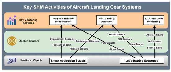
Figure 5.
Key SHM activities in aircraft landing gear systems and applied sensors.
4. Discussion
4.1. Correlation Between Material-Related Failures and Load Monitoring-Based SHM Activities
As reviewed, material fatigue contributes to the primary failure of aircraft landing gear structures. Fatigue failures are primarily initiated and propagated due to cyclic fatigue load and material corrosion. SHM systems, equipped with load sensors such as strain gauges or FBG sensors, offer a solution by continuously monitoring the load levels experienced by landing gear structures during operation. These sensors capture real-time data under dynamic loads, enabling the identification of abnormal stress at unexpected locations due to accidental damages or manufacturing defects, allowing maintenance teams to focus inspections on these critical regions.
In addition, continuous load monitoring also facilitates actual fatigue assessment by recording the complete load history of landing gear structures. This load–time series data can be interpreted to the actual load spectrum, which forms the basis for calculating fatigue accumulation through models such as Miner’s rule, where the cumulative damage caused by varying load cycles is assessed. Numerous studies based on fatigue theories or FEA simulations have confirmed that monitoring structural stress enables accurate calculation of fatigue accumulation in landing gear components [79,80,81,82,83]. By integrating real-time load data, advanced fatigue prediction algorithms have been developed to estimate the actual fatigue life or RUL of components with higher accuracy [65,73,84,85]. This capability supports CBM, allowing for targeted interventions before fatigue damage occurs, thereby reducing the likelihood of unexpected material-related mechanical failures and optimising maintenance schedules.
Although overload-induced failures are less common, they pose a significant risk to aviation safety and should not be overlooked [68]. This highlights the critical role of weight and balance measurement systems, as well as hard landing detection, in preventing such failures or facilitating timely detection and maintenance to mitigate their consequences. Weight and balance measurement systems can monitor the aircraft’s take-off weight and balance, ensuring that landing gear components are not subjected to excessive loads. Overloading can lead to critical failures by subjecting the landing gear to forces that exceed its designed load capacity, particularly during critical phases such as take-off and landing. This excessive loading can result in immediate structural fractures or localised damage to key components. Unbalanced loading distribution increases the likelihood of structural failure due to localised overloading or asymmetrical stresses. If abnormal weight and balance conditions are detected before take-off, the system can issue warnings or trigger maintenance actions to rectify the issue and ensure proper loading before damage occurs.
Hard landings, characterised by higher-than-normal impact forces, are a critical contributor to sudden structural damage in landing gear components. Such events can cause immediate fractures, crack initiation, or exacerbate existing fatigue cracks. A hard landing detection system can identify both the occurrence and severity of hard landings. This information enables maintenance teams to respond promptly by assessing the extent of potential damage immediately after the event. By correlating impact force data with structural load distribution, SHM systems can accurately pinpoint areas susceptible to damage, facilitating targeted inspections and minimising downtime.
4.2. Comparative Analysis of Sensors Used in Load Monitoring-Based SHM
Based on this review, pressure sensors, displacement sensors, accelerometers, strain gauges, and FBG sensors are commonly used in SHM for aircraft landing gears. While each sensor type has its specific applications, some of them are associated with significant limitations when addressing the complex loading and operational conditions of landing gear systems. These limitations highlight the importance of selecting appropriate sensor technologies to ensure accurate and reliable monitoring. Pressure sensors are often installed in the shock absorbers to measure hydraulic pressure and infer the applied load on the aircraft landing gear. However, this method relies on indirect measurements, requiring models or calibration curves to convert pressure data into structural load values, which can introduce significant errors in complex or nonlinear systems. Additionally, pressure sensors are less sensitive to localised stress variations compared to strain-based methods. They also exhibit slower dynamic responses due to hydraulic system inertia, making them less effective in rapidly changing loading conditions [86,87]. Similarly, displacement sensors, such as linear variable differential transformers (LVDTs), provide valuable data on shock strut movement but are limited by structural constraints like restricted installation space and their reliance on indirect measurements for static loads, which can reduce accuracy in complex systems [88]. Additionally, traditional mechanical switches which are often used to measure displacement, require significant loads to achieve the millimetre-level movement necessary to detect shock absorber compression [65]. This dependence on moving parts introduces friction, wear, and calibration drift over time, further compromising the system’s resolution. Accelerometers, while effective in detecting dynamic forces, cannot measure static loads, such as take-off weight, and their sensitivity is often insufficient for precise fatigue monitoring [73].
In contrast, strain gauges and FBG sensors offer significant advantages by directly measuring strain, which has a strong correlation with structural load. This allows for the accurate and reliable detection of both static and dynamic loads without dependence on indirect models or moving components, enhancing their reliability in complex operational conditions [65]. In addition, strain-based sensors demonstrate versatility in addressing various SHM requirements, including weight and balance measurement, hard landing detection, and structural load monitoring. In particular, FBG sensors extend these benefits further with several notable advantages over traditional sensors, as detailed below.
- FBG sensors are highly versatile, making them suitable for the three primary SHM activities mentioned for aircraft landing gears. Their ability to operate effectively in diverse monitoring tasks showcases their adaptability across different applications.
- FBG sensors can offer long-term durability and excellent signal stability under high-vibration loads, which are commonly found in landing gear systems during operation.
- FBG sensors exhibit exceptional stability and resistance to electromagnetic interference, which is particularly beneficial in the demanding operational environment of aircraft landing gear. This ensures reliable performance without being affected by the electromagnetic noise typically present in aircraft systems.
- Another significant advantage of FBG sensors is their compact size. Their small dimensions facilitate easy integration into the structural components of landing gears without interfering with the normal functionality of the monitored parts. This is crucial for maintaining the aerodynamic and mechanical properties of the aircraft components.
- Perhaps the most critical advantage of FBG sensors is their ability to multiplex multiple sensing points along a single optical fibre. This capability allows for the simultaneous monitoring of features such as load and temperature of various locations using a single fibre, which can significantly simplify the wiring in SHM systems and system integration to landing gears. In summary, FBG sensors’ versatility, stability, compactness, and multiplexing capabilities make them a superior choice for SHM in aircraft landing gears, and these advantages have made FBG sensors a growing trend in associated research [67,74,78,89,90].
Despite the excellent usability and performance demonstrated by FBG sensors, specific considerations such as temperature compensation, installation integrity, and signal processing must still be addressed when utilising them in landing gear SHM. Firstly, temperature compensation should be handled properly, as temperature variations can affect the Bragg wavelength and lead to erroneous strain readings. This requires implementing effective temperature compensation techniques or using temperature-insensitive sensor configurations. Secondly, a proper sensor installation that ensures the sensors are securely attached to the monitored structure without introducing stress concentrations or altering the structural behaviour is essential for precise measurement. The optical fibres should be protected from mechanical damage and environmental factors such as moisture, chemicals, and UV radiation, which can lead to performance degradation over time. Furthermore, the interrogators used in FBG sensing systems must have sufficient resolution and stability to detect the small wavelength shifts corresponding to strain changes. Multiplexing multiple FBG sensors along a single optical fibre can significantly reduce system complexity and cost. However, this approach necessitates the meticulous management of optical signals to avoid issues such as crosstalk.
4.3. Aircraft Landing Gear SHM: Safe Life vs. Damage Tolerance
The safe-life philosophy requires the aircraft landing gear components to remain crack-free throughout their service life [91,92]. Typically, the safety assurance of aircraft landing gear components relies on a pre-scheduled, interval-based inspection strategy employing NDT techniques, such as visual inspection, eddy current testing, guided wave monitoring, acoustic emission analysis, ultrasonic testing, magnetic particle testing, and thermographic inspection [88,93,94,95,96,97,98,99]. As discussed above, the safe-life philosophy maximises structural safety but often leads to overly conservative designs, preventing components from being utilised to their full lifecycle potential, and thereby resulting in resource inefficiency. Under this premise, some studies have explored incorporating damage-tolerance principles into aircraft landing gear maintenance, aiming to achieve reliable damage development assessment and failure prevention based on operational and health monitoring data of landing gear components.
For example, Kaplan et al. applied damage-tolerance methods to extend the lifespan of specific landing gear components in a CASA 212 aircraft beyond their original safe-life design limits [22]. This methodology was implemented for critical components of both the main and nose landing gears, including the axle, outer cylinder, torque arms, and upper and lower trunnions. Through loads, stress, and crack growth analyses, they established tailored inspection intervals, demonstrating the potential of damage-tolerance principles to enhance maintenance strategies and extend the operational life of landing gear components. Notably, the authors also mentioned that the successful application of damage-tolerance procedures in this case was due to the specific material properties of the landing gear components. The materials, 4130 steel and DIN 1.6747 steel, exhibited sufficient ductility, resulting in a large critical crack size, making the monitoring and prediction of fatigue crack development feasible.
Two additional studies have demonstrated the application of crack propagation monitoring based on damage-tolerance principles in landing gear structures. One study conducted the real-time monitoring of crack propagation in a landing gear beam structure (made from 7A04-T7351 aluminium alloy) using piezoelectric transducers (PZT) and guided wave testing (GWT). By integrating these techniques with a hierarchical evolution model, the study significantly enhanced the accuracy of damage quantification throughout the entire service life of the component [100]. Another study reported by Qiu et al. monitored crack propagation in a landing gear spar and wing panel, made from 7B04 super-hardness aluminium alloy, during a full-scale aircraft fatigue test. This study also employed PZT and GWT, combining them with a Gaussian mixture model (GMM) to account for time-varying conditions, achieving reliable real-time monitoring and improved damage quantification accuracy [101]. The successful implementation of crack propagation monitoring in these studies can be attributed to several factors. Landing gear beams or spars are typically bigger and more damage tolerant than other critical landing gear components. Cracks in these components tend to propagate more slowly and predictably along well-defined paths, making them more suitable for damage development monitoring compared to other landing gear components with complex geometries and higher operational stresses.
Although these studies focus on specific materials or particular landing gear components, they provide valuable insights and expand the possibilities for future landing gear design and SHM. If novel materials or new designs are introduced, damage-tolerance principle-based landing gear maintenance could become feasible. In such scenarios, the real-time monitoring of fatigue crack initiation and propagation within landing gear structures would become essential and critical. This shift would pave the way for the application of the above-mentioned NDT techniques in continuous in-service landing gear health monitoring.
5. Conclusions
The complexities inherent in aircraft landing gear systems, coupled with the frequently substantial operational stresses endured during critical phases such as take-off and landing, underscore the pivotal role of landing gears in ensuring both the safety of the aircraft and its passengers. The rigorous demands placed on the landing gear make it essential to study occurred failures to identify the causes and prevent recurrence or similar incidents. However, as the modern aviation industry increasingly focuses on cost efficiency and sustainability, proactive approaches that are able to detect early signs of failures before they occur instead of reacting to failures after they have happened are more desirable. In this context, the development of SHM systems for aircraft landing gears has gained increasing attention. Such systems enable continuous monitoring of crucial indicators, allowing for the early detection of potential failures and preventing them from occurring. Moreover, the real-time data provided by SHM systems facilitates CBM by performing more accurate RUL for components using SHM data.
This paper first presents the review results of various material-related landing gear mechanical failure investigations. It has been found that abnormal stress-induced fatigue or corrosion fatigue accounts for the majority of failure causes of mechanical structures in landing gear systems. The existing aircraft landing gear load monitoring-based SHM studies are also reviewed, and weight and balance measurement, hard landing detection, and structural load monitoring are identified as the three most popular research topics in this area. Detailed monitoring methods and commonly used sensors are also discussed in this paper. Notably, FBG sensors are gathering increasing attention due to their superior performance, which includes high sensitivity, immunity to electromagnetic interference, compact size, and the ability to integrate multiple FBGs within a single optical fibre. The integration potential and robustness of FBG sensors align well with the demanding environmental conditions and operational stress experienced by aircraft landing gears, thus positioning them as a particularly promising candidate for use in SHM systems of aircraft landing gears.
Moreover, the article also reviews studies that explore incorporating damage-tolerance principles into landing gear SHM. These studies underscore the possibility of extending damage-tolerance-based maintenance to a broader range of landing gear applications, especially with the adoption of novel materials and advanced designs, paving the way for enhanced safety and maintenance efficiency in next-generation aircraft landing gear systems.
Author Contributions
Conceptualisation, K.D., A.P.O. and Y.Z.; methodology, K.D., A.P.O. and Y.Z.; formal analysis and investigation, K.D., A.P.O. and Y.Z.; writing—original draft preparation, K.D.; writing—review and editing, A.P.O., Y.X., M.S. and Y.Z.; supervision, Y.Z.; project administration, Y.Z.; funding acquisition, Y.Z. and Y.X. All authors have read and agreed to the published version of the manuscript.
Funding
This research was funded by Airbus Operations Limited, and the reference number for the funding is CU01921121.
Data Availability Statement
No new data were created or analysed in this study. Data sharing is not applicable to this article.
Conflicts of Interest
The authors declare no conflicts of interest. The funders had no role in the design of this study; in the collection, analyses, or interpretation of data; in the writing of the manuscript; or in the decision to publish the results.
References
- Krüger, W.; Besselink, I.; Cowling, D.; Doan, D.B.; Kortüm, W.; Krabacher, W. Aircraft Landing Gear Dynamics: Simulation and Control. Veh. Syst. Dyn. 1997, 28, 119–158. [Google Scholar] [CrossRef]
- Federal Aviation Authority. Chapter 13—Aircraft Landing Gear Systems. In Aviation Maintenance Technician Handbook—Airframe; Federal Aviation Authority: Washington, DC, USA, 2014. [Google Scholar]
- Young, D.W. Aircraft Landing Gears—The Past, Present and Future. Proc. Inst. Mech. Eng. Part D Transp. Eng. 1986, 200, 75–92. [Google Scholar] [CrossRef]
- Greenbank, S.J. Landing Gear—The Aircraft Requirement. Proc. Inst. Mech. Eng. Part G J. Aerosp. Eng. 1991, 205, 27–34. [Google Scholar] [CrossRef]
- Diltemiz, S.F. Failure Analysis of Aircraft Main Landing Gear Cylinder Support. Eng. Fail. Anal. 2021, 129, 105711. [Google Scholar] [CrossRef]
- McBrearty, J.F. A Critical Study of Aircraft Landing Gears. J. Aeronaut. Sci. 1948, 15, 263–280. [Google Scholar] [CrossRef]
- Airbus, A. Statistical Analysis of Commercial Aviation Accidents 1958–2023; Accident Statistics: Blagnac, France, 2024. [Google Scholar]
- Reveley, M.S.; Briggs, J.L.; Thomas, M.A.; Evans, J.K.; Jones, S.M. An Examination of Commercial Aviation Accidents and Incidents Related to Integrated Vehicle Health Management. In Proceedings of the 9th AIAA Aviation Technology, Integration and Operations (ATIO) Conference, Aircraft Noise and Emissions Reduction Symposium (ANERS), Hilton Head, SC, USA, 21–23 September 2009. [Google Scholar]
- Karpenko, M. Landing Gear Failures Connected with High-Pressure Hoses and Analysis of Trends in Aircraft Technical Problems. Aviation 2022, 26, 145–152. [Google Scholar] [CrossRef]
- Lee, E.U.; Waldman, J. Corrosion of Aircraft Landing Gear Steels. Nav. Eng. J. 1994, 106, 77–83. [Google Scholar] [CrossRef]
- Czaban, M. Aircraft Corrosion—Review of Corrosion Processes and Its Effects in Selected Cases. Fatigue Aircr. Struct. 2018, 2018, 5–20. [Google Scholar] [CrossRef]
- Chang, Q.C.; Xue, C.J. Reliability Analysis and Experimental Verification of Landing-Gear Steering Mechanism Considering Environmental Temperature. J. Aircr. 2018, 55, 1154–1164. [Google Scholar] [CrossRef]
- Li, S.; Dong, L.; Zheng, H.; Wu, C.; Wang, H.; Ling, D.; Wang, Q. Research Progress of Stress Corrosion Cracking of Ultra-High Strength Steels for Aircraft Landing Gear. J. Chin. Soc. Corros. Prot. 2023, 43, 1178–1188. [Google Scholar] [CrossRef]
- Lin, X.; Zhang, R.; Mei, Y.; Yang, L.; Yang, F.; Dou, B.; Wei, Y. Corrosion Electrochemical Behavior of Cadmium-Plated 4340 Steel in Aircraft Landing Gears under Thin Electrolyte Layers of Potassium Acetate Deicing Fluid. New J. Chem. 2019, 43, 14435–14442. [Google Scholar] [CrossRef]
- Rivas-Lopez, M.; Fuentes, W.F.; Sergiyenko, O. (Eds.) . Structural Health Monitoring—Measurement Methods and Practical Applications; IntechOpen: London, UK, 2017. [Google Scholar]
- Cawley, P. Structural Health Monitoring: Closing the Gap between Research and Industrial Deployment. Struct. Health Monit. 2018, 17, 1225–1244. [Google Scholar] [CrossRef]
- Güemes, A. SHM Technologies and Applications in Aircraft Structures. In Proceedings of the 5th International Symposium on NDT in Aerospace, Singapore, 13–15 November 2013. [Google Scholar]
- Zinno, R.; Artese, S.; Clausi, G.; Magarò, F.; Meduri, S.; Miceli, A.; Venneri, A. Structural Health Monitoring (SHM). In The Internet of Things for Smart Urban Ecosystems; Cicirelli, F., Guerrieri, A., Mastroianni, C., Spezzano, G., Vinci, A., Eds.; Springer International Publishing: Cham, Switzerland, 2019; pp. 225–249. ISBN 978-3-319-96550-5. [Google Scholar]
- Forrest, C.; Forrest, C.; Wiser, D. Landing Gear Structural Health Monitoring (SHM). Procedia Struct. Integr. 2017, 5, 1153–1159. [Google Scholar] [CrossRef]
- Divakaran, V.N.; Dr Ravikumar, G.V.; Rao Patnala, S. Aircraft Landing Gear Design & Development; White Paper; Infosys Limited: Chiyoda, Tokyo, 2018. [Google Scholar]
- Toor, P.M. A Review of Some Damage Tolerance Design Approaches for Aircraft Structures. Eng. Fract. Mech. 1973, 5, 837–880. [Google Scholar] [CrossRef]
- Kaplan, M.P.; Willis, T.; Wolff, T.A. Damage Tolerance Assessment of CASA Landing Gear. In Proceedings of the SAE Technical Papers; SAE International: Warrendale, PA, USA, 1997. [Google Scholar]
- El Mir, H.; King, S.; Skote, M.; Alam, M.; Place, S. Landing Gear Health Assessment: Synergising Flight Data Analysis with Theoretical Prognostics in a Hybrid Assessment Approach. PHM Soc. Eur. Conf. 2024, 8, 10. [Google Scholar] [CrossRef]
- Hsu, T.H.; Chang, Y.J.; Hsu, H.K.; Chen, T.T.; Hwang, P.W. Predicting the Remaining Useful Life of Landing Gear with Prognostics and Health Management (PHM). Aerospace 2022, 9, 462. [Google Scholar] [CrossRef]
- Gerdes, M.; Scholz, D.; Galar, D. Effects of Condition-Based Maintenance on Costs Caused by Unscheduled Maintenance of Aircraft. J. Qual. Maint. Eng. 2016, 22, 394–417. [Google Scholar] [CrossRef]
- Benassi, L.; Neumair, M.; Buderath, M. A Structural Health Monitoring System as Part of an Aircraft Integrated Vehicle Health Monitoring Architecture for Condition-Based Maintenance. In Proceedings of the Structural Health Monitoring 2009: From System Integration to Autonomous Systems—Proceedings of the 7th International Workshop on Structural Health Monitoring, IWSHM 2009, Stanford, CA, USA, 9–11 September 2009; Volume 1. [Google Scholar]
- Chang, Y.J.; Hsu, H.K.; Hsu, T.H.; Chen, T.T.; Hwang, P.W. The Optimization of a Model for Predicting the Remaining Useful Life and Fault Diagnosis of Landing Gear. Aerospace 2023, 10, 963. [Google Scholar] [CrossRef]
- Ahmadi, A.; Fransson, T.; Crona, A.; Klein, M.; Söderholm, P. Integration of RCM and PHM for the next Generation of Aircraft. In Proceedings of the IEEE Aerospace Conference Proceedings, Big Sky, MT, USA, 7–14 March 2009. [Google Scholar]
- Haider, S. Overview of Prognostics and Health Management for Landing Gear Maintenance. In Proceedings of the Proceedings—Annual Reliability and Maintainability Symposium, Orlando, FL, USA, 28–31 January 2019; Volume 2019. [Google Scholar]
- Skorupka, Z.; Tywoniuk, A. Health Monitoring in Landing Gears. J. KONES 2019, 26, 167–174. [Google Scholar] [CrossRef]
- Di Sante, R. Fibre Optic Sensors for Structural Health Monitoring of Aircraft Composite Structures: Recent Advances and Applications. Sensors 2015, 15, 18666–18713. [Google Scholar] [CrossRef]
- Qing, X.; Li, W.; Wang, Y.; Sun, H. Piezoelectric Transducer-Based Structural Health Monitoring for Aircraft Applications. Sensors 2019, 19, 545. [Google Scholar] [CrossRef] [PubMed]
- Vujić, D. Wireless Sensor Networks Applications in Aircraft Structural Health Monitoring. J. Appl. Eng. Sci. 2015, 13, 79–86. [Google Scholar] [CrossRef]
- Yedavalli, R.K.; Belapurkar, R.K. Application of Wireless Sensor Networks to Aircraft Control and Health Management Systems. J. Control Theory Appl. 2011, 9, 28–33. [Google Scholar] [CrossRef]
- Infante, V.; Fernandes, L.; Freitas, M.; Baptista, R. Failure Analysis of a Nose Landing Gear Fork. Eng. Fail. Anal. 2017, 82, 554–565. [Google Scholar] [CrossRef]
- Turan, D.; Karabayrak, B.; Baskut, S.; Dalkilic, S. Failure Analysis of Landing Gears Strut Bearings. Eng. Fail. Anal. 2017, 82, 525–532. [Google Scholar] [CrossRef]
- Komai, K. 4.13—Corrosion Fatigue. Compr. Struct. Integr. 2003, 4, 345–358. [Google Scholar] [CrossRef]
- Jayaraman, N.; Prevey, P.; Ontko, N.; Shepard, M.; Ware, R.; Coate, J. Comparison of Mechanical Suppression by Shot Peening and Low Plasticity Burnishing to Mitigate SCC and Corrosion Fatigue Failures in 300m Landing Gear Steel. In Proceedings of the International Conference on Shot Peening, Paris, France, 6–9 September 2005. [Google Scholar]
- Asi, O.; Yeşil, Ö. Failure Analysis of an Aircraft Nose Landing Gear Piston Rod End. Eng. Fail. Anal. 2013, 32, 283–291. [Google Scholar] [CrossRef]
- Infante, V.; Reis, L.; de Freitas, M. Failure Analysis of Landing Gears Trunnions Due to Service. Eng. Fail. Anal. 2014, 41, 118–123. [Google Scholar] [CrossRef]
- Zucca, G.; Di Francesco, V.; Bernabei, M.; De Paolis, F. Failure Investigation: In Flight Loss of a Main Landing Gear Door of a Transport Aircraft. Procedia Struct. Integr. 2017, 3, 553–561. [Google Scholar]
- Ossa, E.A. Failure Analysis of a Civil Aircraft Landing Gear. Eng. Fail. Anal. 2006, 13, 1177–1183. [Google Scholar] [CrossRef]
- Azevedo, C.R.F.; Hippert, E.; Spera, G.; Gerardi, P. Aircraft Landing Gear Failure: Fracture of the Outer Cylinder Lug. Eng. Fail. Anal. 2002, 9, 1–15. [Google Scholar] [CrossRef]
- Barter, S.A. Investigation of a Boeing 747 Wing Main Landing Gear Trunnion Failure. Eng. Fail. Anal. 2013, 35, 387–396. [Google Scholar] [CrossRef]
- Eliaz, N.; Sheinkopf, H.; Shemesh, G.; Artzi, H. Cracking in Cargo Aircraft Main Landing Gear Truck Beams Due to Abusive Grinding Following Chromium Plating. Eng. Fail. Anal. 2005, 12, 337–347. [Google Scholar] [CrossRef]
- Bagnoli, F.; Dolce, F.; Colavita, M.; Bernabei, M. Fatigue Fracture of a Main Landing Gear Swinging Lever in a Civil Aircraft. Eng. Fail. Anal. 2008, 15, 755–765. [Google Scholar] [CrossRef]
- Lee, H.C.; Hwang, Y.H.; Kim, T.G. Failure Analysis of Nose Landing Gear Assembly. Eng. Fail. Anal. 2003, 10, 77–84. [Google Scholar] [CrossRef]
- Franco, L.A.L.; Lourenço, N.J.; Graça, M.L.A.; Silva, O.M.M.; de Campos, P.P.; von Dollinger, C.F.A. Fatigue Fracture of a Nose Landing Gear in a Military Transport Aircraft. Eng. Fail. Anal. 2006, 13, 474–479. [Google Scholar] [CrossRef]
- Ossa, E.A.; Paniagua, M. Suspension and Landing Gear Failures. In Handbook of Materials Failure Analysis with Case Studies from the Aerospace and Automotive Industries; Butterworth-Heinemann: Oxford, UK, 2016. [Google Scholar]
- Roth, M.; Yanishevsky, M.; Beaudet, P. Failure Analysis of Aircraft Landing Gear Components. In ASM Failure Analysis Case Histories: Air and Spacecraft; ASM International: Materials Park, OH, USA, 2019. [Google Scholar]
- Zhu, M.; Xuan, F. Fatigue Crack Initiation Potential from Defects in Terms of Local Stress Analysis. Chin. J. Mech. Eng. 2014, 27, 496–503. [Google Scholar] [CrossRef]
- Lu, L.; Chen, H.; Ren, M.; Xu, S.; Li, Y.; Zhou, T.; Yang, Y. Study on Fatigue Life of Aluminum Alloy 6061-T6 Based on Random Defect Characteristics. Materials 2024, 17, 1133. [Google Scholar] [CrossRef]
- Xue, C.J.; Han, Y.; Qi, W.G.; Dai, J.H. Landing-Gear Drop-Test Rig Development and Application for Light Airplanes. J. Aircr. 2012, 49, 2064–2076. [Google Scholar] [CrossRef]
- Holmes, G.; Sartor, P.; Reed, S.; Southern, P.; Worden, K.; Cross, E. Prediction of Landing Gear Loads Using Machine Learning Techniques. Struct. Health Monit. 2016, 15, 568–582. [Google Scholar] [CrossRef]
- Sobieszek, A.; Paprzycki, I.; Tywoniuk, A. Landing Gear Dynamic Tests With Strain Gages. J. KONES 2015, 22, 221–227. Available online: https://www.researchgate.net/publication/340032435 (accessed on 17 March 2025).
- Li, W.; Chen, S.; Chu, Y.; Huang, P.; Yan, G. Wide-Range Fiber Bragg Grating Strain Sensor for Load Testing of Aircraft Landing Gears. Optik 2022, 262, 169290. [Google Scholar] [CrossRef]
- Braunfelds, J.; Spolitis, S.; Porins, J.; Bobrovs, V. Fiber Bragg Grating Sensors Integration in Fiber Optical Systems. In Application of Optical Fiber in Engineering; IntechOpen: London, UK, 2021. [Google Scholar]
- Othonos, A. Fiber Bragg Gratings. Rev. Sci. Instrum. 1997, 68, 4309–4341. [Google Scholar]
- Chen, J.; Liu, B.; Zhang, H. Review of Fiber Bragg Grating Sensor Technology. Front. Optoelectron. China 2011, 4, 204–212. [Google Scholar]
- Campanella, C.E.; Cuccovillo, A.; Campanella, C.; Yurt, A.; Passaro, V.M.N. Fibre Bragg Grating Based Strain Sensors: Review of Technology and Applications. Sensors 2018, 18, 3115. [Google Scholar] [CrossRef]
- Gardiner, D. Aircraft Weight & Balance Handbook; ReVision; FAA-H-8083-1A; Federal Aviation Administration: Oklahoma City, OK, USA, 2010. [Google Scholar]
- Brindisi, A.; Ameduri, S.; Concilio, A.; Ciminello, M.; Leone, M.; Iele, A.; Consales, M.; Cusano, A. A Multi-Scaled Demonstrator for Aircraft Weight and Balance Measurements Based on FBG Sensors: Design Rationale and Experimental Characterization. Meas. J. Int. Meas. Confed. 2019, 141, 113–123. [Google Scholar] [CrossRef]
- Tripero, A.M.G.; Arevalo, J.L.L.; Pena, E.L. Weight on Wheel System Based on Strain Gauges. In Proceedings of the 28th Congress of the International Council of the Aeronautical Sciences 2012, ICAS 2012, Brisbane, Australia, 23–28 September 2012; Volume 5. [Google Scholar]
- Jakovljevic, I.; Mirosavljevic, P.; Mijailovic, R. Optimization of Aircraft Center of Gravity. Tehnika 2017, 72, 411–414. [Google Scholar] [CrossRef]
- Jiménez, A.; Novillo, E.; Morante, E.; Chamorro, E. Load Detection and Fatigue Health Monitoring Equipment Design for Landing Gears. In Proceedings of the ASME International Mechanical Engineering Congress and Exposition, Proceedings (IMECE), Montreal, QC, Canada, 14–20 November 2014; Volume 1. [Google Scholar]
- Skorupka, Z. Laboratory Investigations on Landing Gear Ground Reactions (Load) Measurement. J. KONES 2017, 24, 225–230. Available online: https://www.researchgate.net/publication/329416379 (accessed on 17 March 2025).
- Iele, A.; Leone, M.; Consales, M.; Persiano, G.V.; Brindisi, A.; Ameduri, S.; Concilio, A.; Ciminello, M.; Apicella, A.; Bocchetto, F.; et al. Load Monitoring of Aircraft Landing Gears Using Fiber Optic Sensors. Sens. Actuators A Phys. 2018, 281, 31–41. [Google Scholar] [CrossRef]
- Oh, Y.-K.; Sim, S.-K.; Shin, K.-S. A Study of the Effects of Hard Landing on Aircraft Structure. J. Korea Inst. Mil. Sci. Technol. 2011, 14, 805–811. [Google Scholar] [CrossRef]
- Hard Landing Involving an Airbus A330-323, 9M-MTA; Australian Transport Safety Bureau: Canberra, Australia, 2017.
- Airbus. Hard Landing – A Case Study for Crews and Maintenance Personnel. Airbus Safety First, January 2014. Available online: https://safetyfirst.airbus.com/hard-landing-a-case-study-for-crews-and-maintenance-personnel/ (accessed on 17 March 2025).
- Schmidt, R.K. System and Method for Determining Aircraft Hard Landing Events From Inertial and Aircraft Reference Frame Data. US Patent US20070008187A1, 15 September 2009. [Google Scholar]
- Coffin, L.T.; Phan, N.; Wiser, D.; Nance, K.; Starr, C. Aircraft Landing Gear Fluid Level and Landing Energy Monitoring System. In Proceedings of the 6th European Workshop—Structural Health Monitoring 2012, EWSHM 2012, Dresden, Germany, 3–6 July 2012; Volume 2. [Google Scholar]
- Dziendzikowski, M.; Kurnyta, A.; Reymer, P.; Kurdelski, M.; Klysz, S.; Leski, A.; Dragan, K. Application of Operational Load Monitoring System for Fatigue Estimation of Main Landing Gear Attachment Frame of an Aircraft. Materials 2021, 14, 6564. [Google Scholar] [CrossRef] [PubMed]
- Grooteman, F.; Goutagny, R.; Davies, C.; van Leest, T.; Platt, I.; Symons, J. Advanced Landing Gear Fibre Bragg Grating Sensing and Monitoring System. Adv. Struct. Eng. 2022, 25, 2382–2399. [Google Scholar] [CrossRef]
- Brindisi, A.; Vendittozzi, C.; Travascio, L.; Di Palma, L.; Ignarra, M.; Fiorillo, V.; Concilio, A. A Preliminary Assessment of an FBG-Based Hard Landing Monitoring System. Photonics 2021, 8, 450. [Google Scholar] [CrossRef]
- Brindisi, A.; Vendittozzi, C.; Travascio, L.; Di Palma, L.; Belardo, M.; Ignarra, M.; Fiorillo, V.; Concilio, A. Preliminary Assessment of an FBG-Based Landing Gear Weight on Wheel System. Actuators 2022, 11, 191. [Google Scholar] [CrossRef]
- Kedir, Y.A.; Lemu, H.G. Prediction of Fatigue Crack Initiation under Variable Amplitude Loading: Literature Review. Metals 2023, 13, 487. [Google Scholar] [CrossRef]
- Petrone, G.; Bruno, M.; Bocchetto, F.; Breglio, G.; Pugliese, M.; Caldara, A.; Nocella, A.; Cavallari, A.; Lo Moriello, S.S.; Capuano, G.; et al. An Innovative Health Monitoring System for Aircraft Landing Gears. In Proceedings of the 8th European Workshop on Structural Health Monitoring, EWSHM 2016, Bilbao, Spain, 5–8 July 2016; Volume 1. [Google Scholar]
- Lok, S.K.; Paul, M.J.; Upendranath, V. Prescience Life of Landing Gear Using Multiaxial Fatigue Numerical Analysis. Procedia Eng. 2014, 86, 775–779. [Google Scholar]
- Ge, Z.; Zhu, S.; Ma, T.; Wan, F.; Zhang, C.; Liu, G.; Wei, H. Fatigue Life Analysis of Landing Gear Side Strut Based on Finite Element. In Proceedings of the Proceedings—2022 Prognostics and Health Management Conference, PHM-London 2022, London, UK, 27–29 May 2022. [Google Scholar]
- Korba, P.; Huňady, R.; Hovanec, M.; Rácek, B.; Pavelka, P. Fatigue Life Analysis of an Aircraft Brake Component to Prevent Damage and Ensure Operational Safety. Eng. Fail. Anal. 2021, 129, 105653. [Google Scholar] [CrossRef]
- Gerhardinger, D.; Abramovic, B.; Fratrovic, T.; Domitrovic, A. Landing Gear Leg Fatigue Life Analysis for Light Aircraft. Transp. Res. Procedia 2022, 64, 14–24. [Google Scholar]
- Raouf, I.; Kumar, P.; Cheon, Y.; Tanveer, M.; Jo, S.-H.; Kim, H.S. Advances in Prognostics and Health Management for Aircraft Landing Gear—Progress, Challenges, and Future Possibilities. Int. J. Precis. Eng. Manuf. Technol. 2025, 12, 301–320. [Google Scholar] [CrossRef]
- Gerhardinger, D.; Domitrovic, A.; Bazijanac, E. Fatigue Life Prognosis of a Light Aircraft Landing Gear Leg. In Proceedings of the Annual Conference of the Prognostics and Health Management Society, PHM, Virtual, 9–13 November 2020; Volume 12. [Google Scholar]
- Yang, L.; Yanguang, H. A Study on Life Monitoring of Landing Gear Based on Weight Parameter and Fatigue Loads Interaction. In Proceedings of the 2015 IEEE Conference on Prognostics and Health Management: Enhancing Safety, Efficiency, Availability, and Effectiveness of Systems Through PHAf Technology and Application, PHM 2015, Austin, TX, USA, 22-25 June 2015. [Google Scholar]
- Brindisi, A.; Vendittozzi, C.; Travascio, L.; Di Palma, L.; Concilio, A. Landing Gear Hard Impact: Preliminary Study on Optic Monitoring System. Proc. Inst. Mech. Eng. Part C J. Mech. Eng. Sci. 2023, 237, 4151–4162. [Google Scholar] [CrossRef]
- Finance, R.J. Device for Detecting Hard Landings. USA Patent US4278219A, 14 July 1981. [Google Scholar]
- Vinella, J.C.J. Remote Sensing of Aircraft Landing Gear Metallic Linkage Interfaces Using Eddy Current Sensors. In Proceedings of the International Telemetering Conference Proceedings; International Telemetering Conference Proceedings, Las Vegas, NV, USA, 23–26 October 2023. [Google Scholar]
- Xu, H.; Zheng, X.; Zhao, W.; Sun, X.; Li, F.; Du, Y.; Liu, B.; Gao, Y. High Precision, Small Size and Flexible FBG Strain Sensor for Slope Model Monitoring. Sensors 2019, 19, 2716. [Google Scholar] [CrossRef] [PubMed]
- Iadicicco, A.; Natale, D.; Palma, P.D.; Spinaci, F.; Apicella, A.; Campopiano, S. Strain Monitoring of a Composite Drag Strut in Aircraft Landing Gear by Fiber Bragg Grating Sensors. Sensors 2019, 19, 2239. [Google Scholar] [CrossRef] [PubMed]
- Hoole, J.; Sartor, P.; Cooper, J. Safe-Life Fatigue and Sensitivity Analysis: A Pathway Towards Embracing Uncertainty? In Proceedings of the 5th Aircraft Structural Design Conference, Manchester, UK, 3–6 October 2016. [Google Scholar]
- Braga, D.F.O.; Tavares, S.M.O.; Da Silva, L.F.M.; Moreira, P.M.G.P.; De Castro, P.M.S.T. Advanced Design for Lightweight Structures: Review and Prospects. Prog. Aerosp. Sci. 2014, 69, 29–39. [Google Scholar] [CrossRef]
- Phillips, P.; Diston, D.; Starr, A.; Payne, J.; Pandya, S. A Review on the Optimisation of Aircraft Maintenance with Application to Landing Gears. In Proceedings of the Engineering Asset Lifecycle Management—Proceedings of the 4th World Congress on Engineering Asset Management, WCEAM 2009, Athens, Greece, 28–30 September 2009. [Google Scholar]
- Pullin, R.; Holford, K.M.; Evans, S.L.; Baxter, M.G. Acoustic Emission Testing of a Landing Gear Component. Adv. Mater. Res. 2006, 13–14, 29–34. [Google Scholar] [CrossRef]
- Ulus, Ö.; Davarcı, F.E.; Gültekin, E.E. Non-Destructive Testing Methods Commonly Used in Aviation. Int. J. Aeronaut. Astronaut. 2024, 5, 10–22. [Google Scholar] [CrossRef]
- Rose, J.L.; Soley, L.E. Ultrasonic Guided Waves for Anomaly Detection in Aircraft Components. Mater. Eval. 2000, 58, 1080–1086. [Google Scholar]
- Eisenmann, D.J.; Enyart, D.; Lo, C.; Brasche, L. Review of Progress in Magnetic Particle Inspection. AIP Conf. Proc. 2014, 1581, 1505–1510. [Google Scholar]
- Ramachandra, L.S.; Ali, F.; Plastropoulos, A.; Avdelidis, N.P.; Jennions, I.; Skote, M. Evaluation of Aircraft Wheel and Brake Temperatures Based on Infrared Thermographic Imaging. In Proceedings of the Thermosense: Thermal Infrared Applications XLVI, National Harbor, MD, USA, 21–26 April 2024; Avdelidis, N.P., Ferrarini, G., López, F., Eds.; SPIE: Bellingham, WA, USA, 2024; p. 31. [Google Scholar]
- Chen, D.; Zhang, X.; Zhang, G.; Zhang, Y.; Li, X. Infrared Thermography and Its Applications in Aircraft Non-Destructive Testing. In Proceedings of the Proceedings—2016 International Conference on Identification, Information and Knowledge in the Internet of Things, IIKI 2016, Beijing, China, 20–21 October 2016; Volume 2018. [Google Scholar]
- Yuan, S.; Jing, H.; Wang, Y.; Zhang, J. A Whole Service Time SHM Damage Quantification Model Hierarchical Evolution Mechanism. Mech. Syst. Signal Process. 2024, 209, 111064. [Google Scholar] [CrossRef]
- Qiu, L.; Yuan, S.; Bao, Q.; Mei, H.; Ren, Y. Crack Propagation Monitoring in a Full-Scale Aircraft Fatigue Test Based on Guided Wave-Gaussian Mixture Model. Smart Mater. Struct. 2016, 25, 055048. [Google Scholar] [CrossRef]
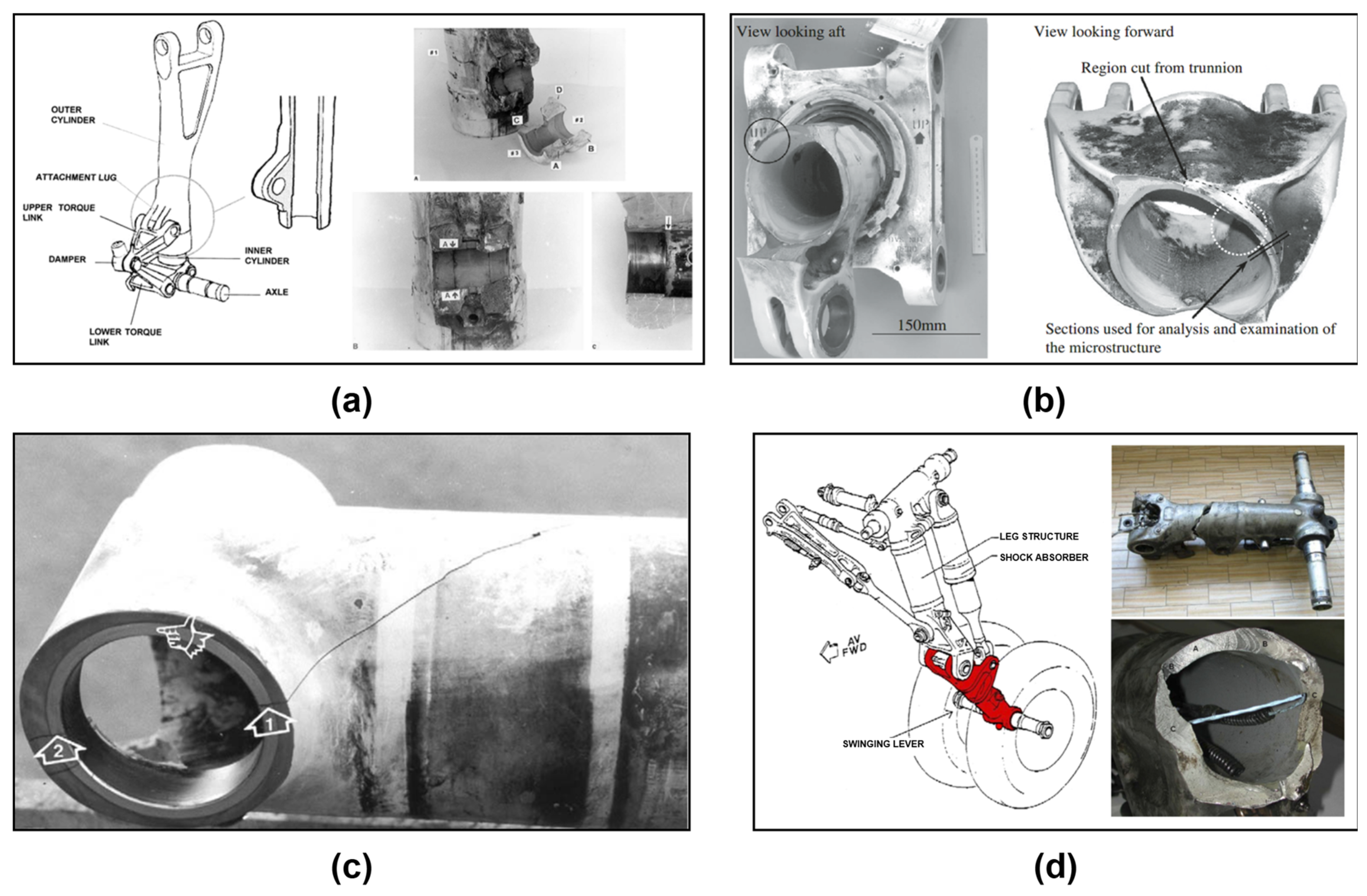
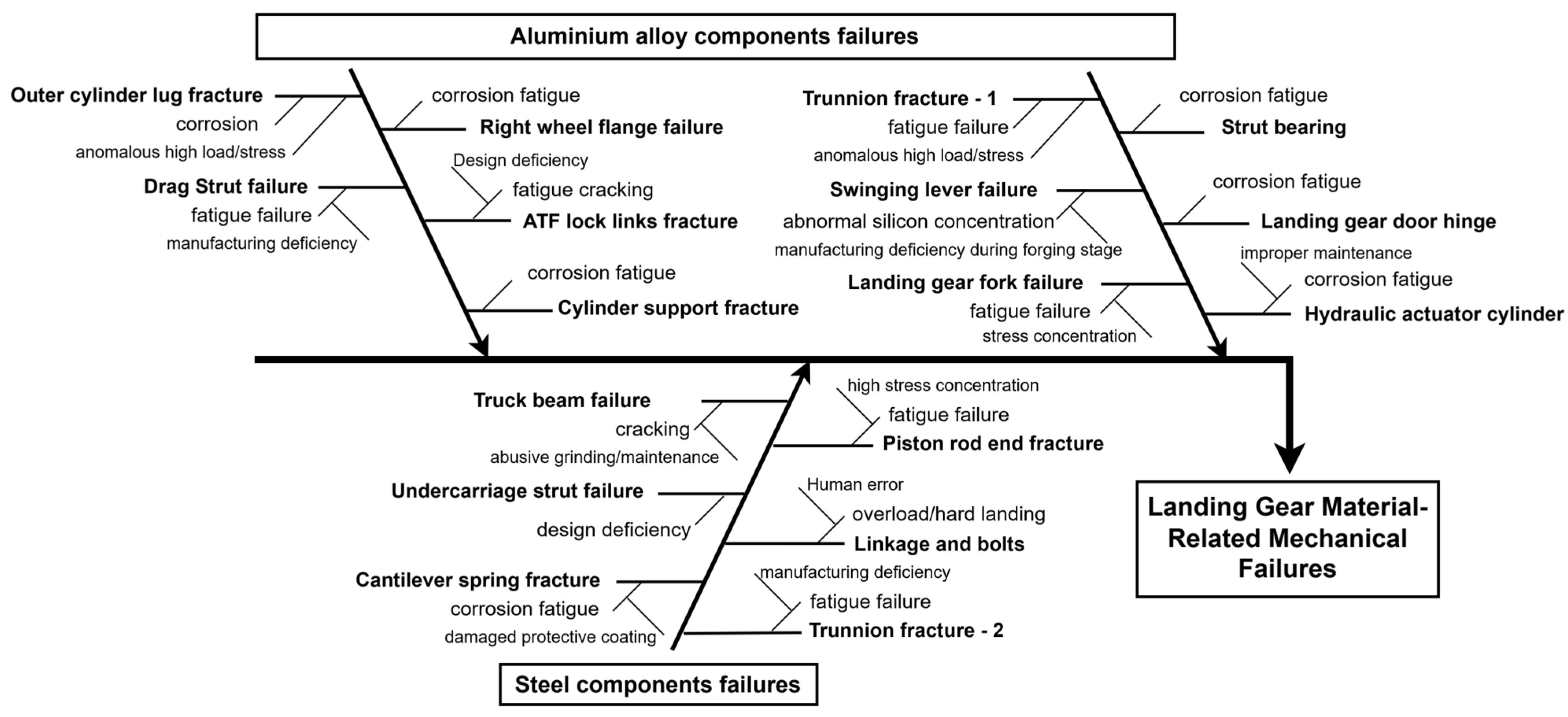
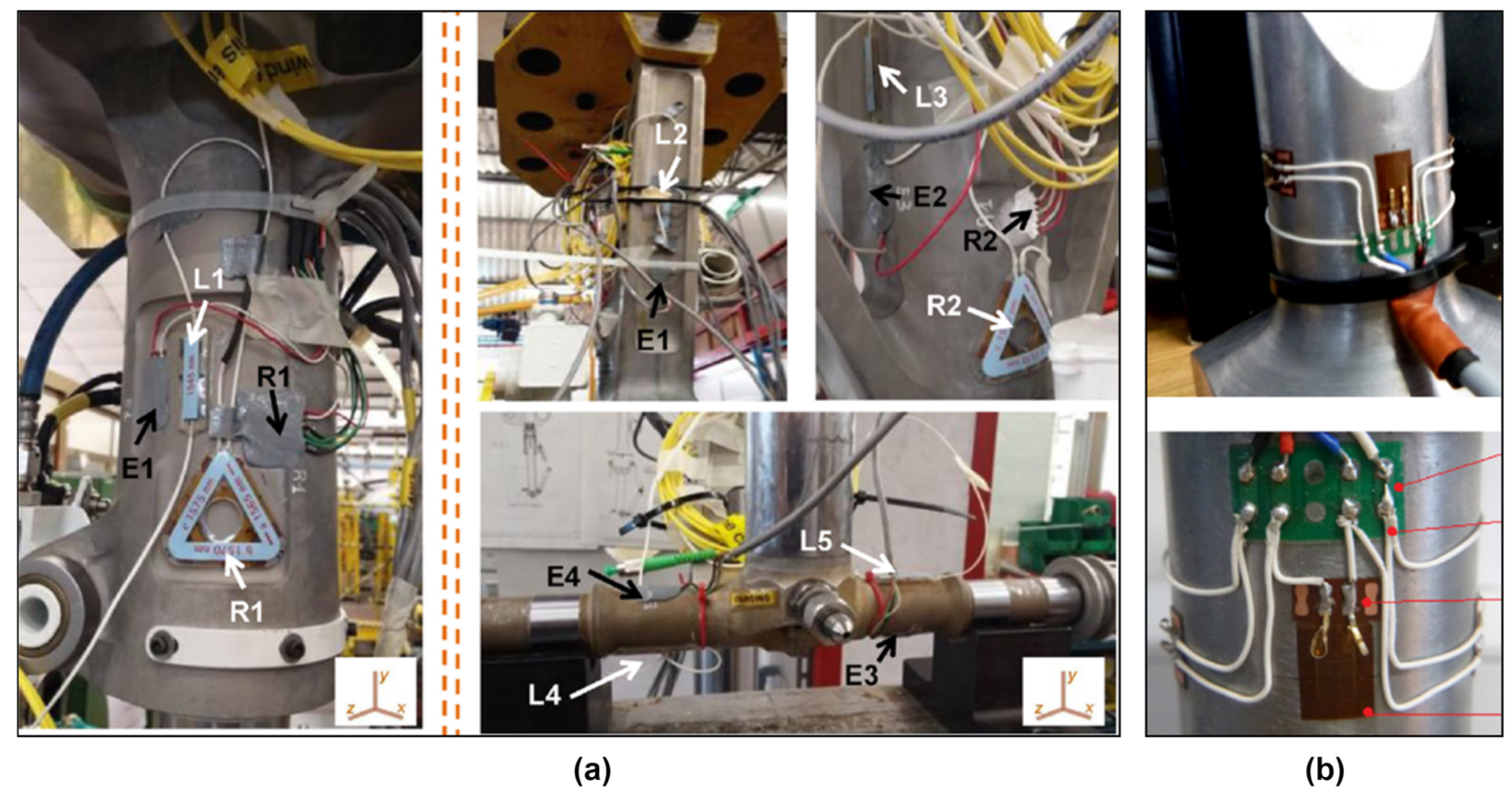
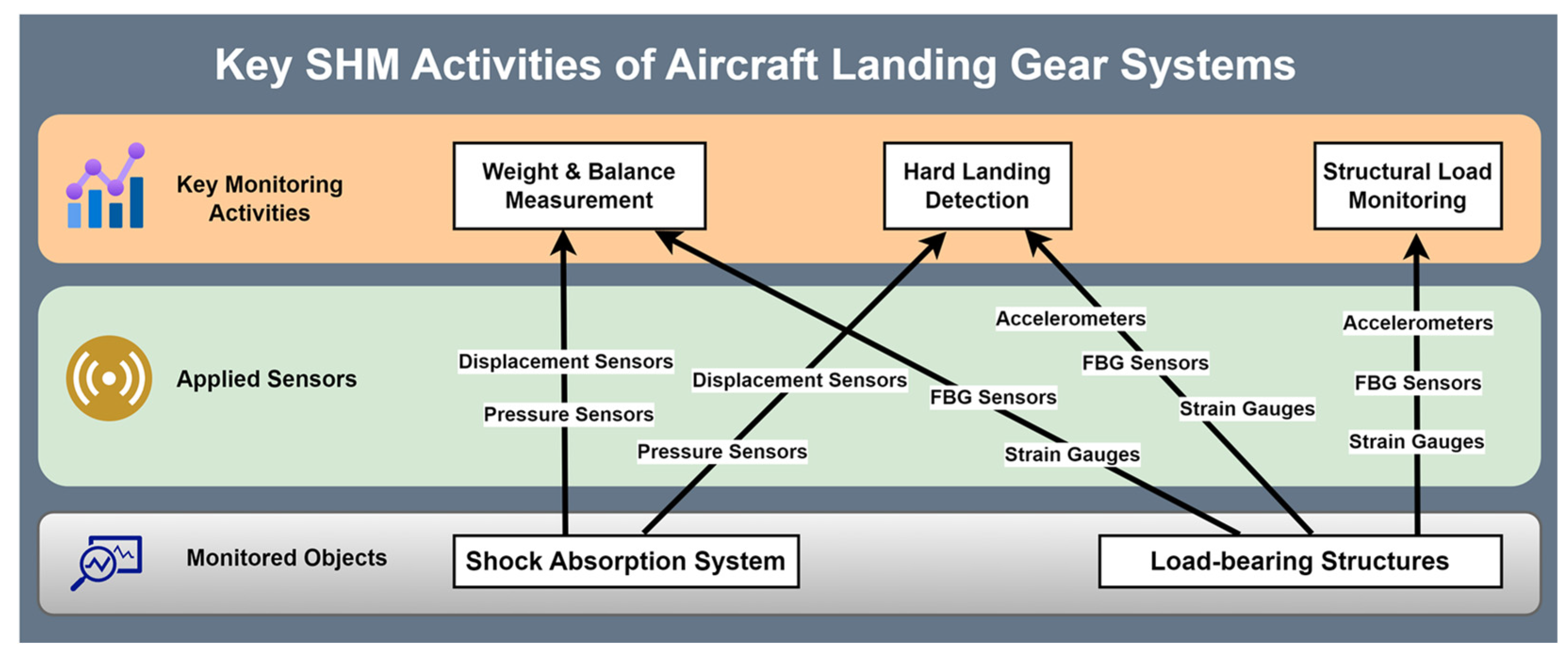
Disclaimer/Publisher’s Note: The statements, opinions and data contained in all publications are solely those of the individual author(s) and contributor(s) and not of MDPI and/or the editor(s). MDPI and/or the editor(s) disclaim responsibility for any injury to people or property resulting from any ideas, methods, instructions or products referred to in the content. |
© 2025 by the authors. Licensee MDPI, Basel, Switzerland. This article is an open access article distributed under the terms and conditions of the Creative Commons Attribution (CC BY) license (https://creativecommons.org/licenses/by/4.0/).