
Heat Shield Properties of Lightweight Ablator Series for Transfer Vehicle Systems with Different Laminated Structures Under High Enthalpy Flow Environments


Abstract
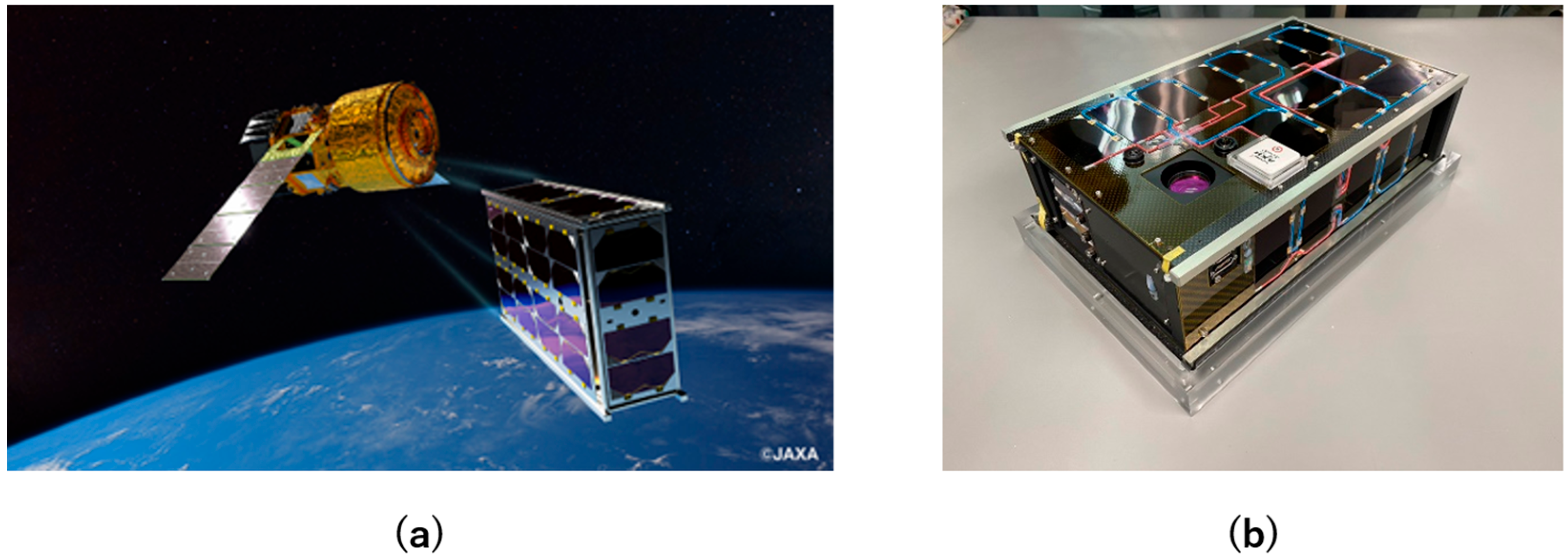
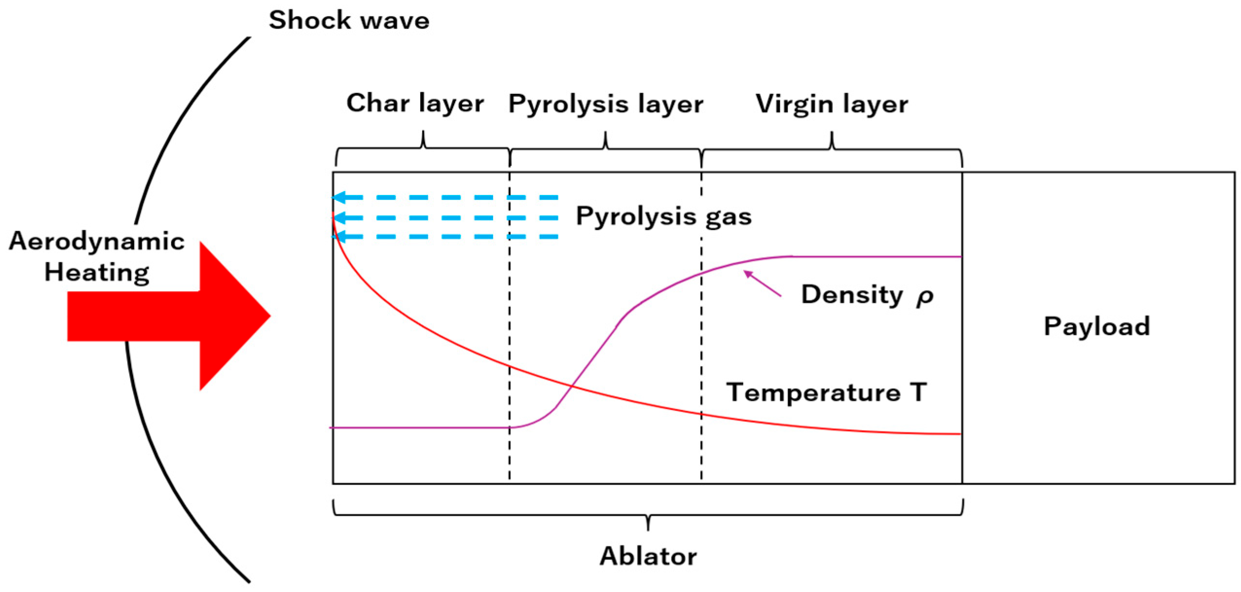
:1. Introduction
2. Materials and Methods
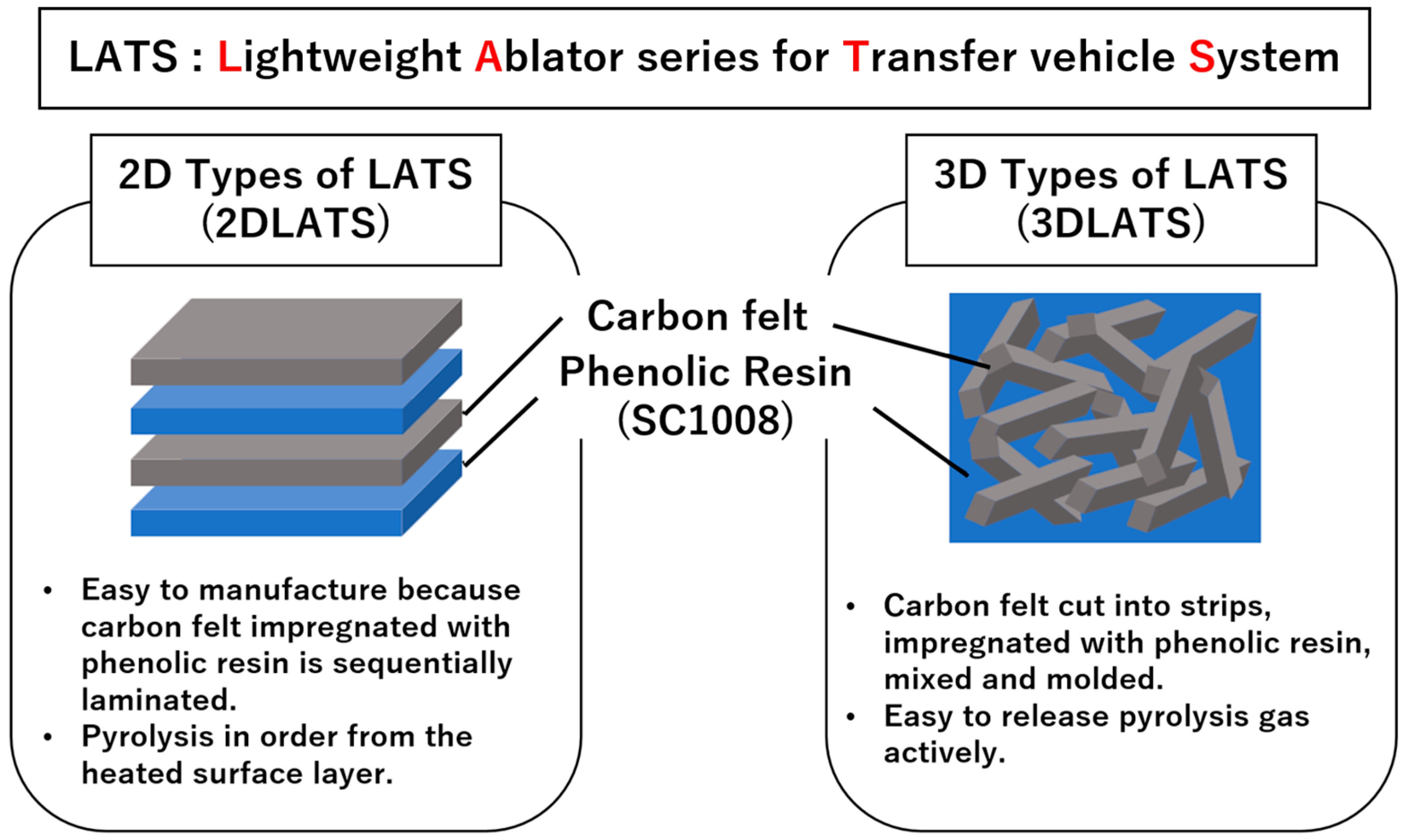
2.1. Description of the Lightweight Ablator Series for Transfer Vehicle Systems (LATS)
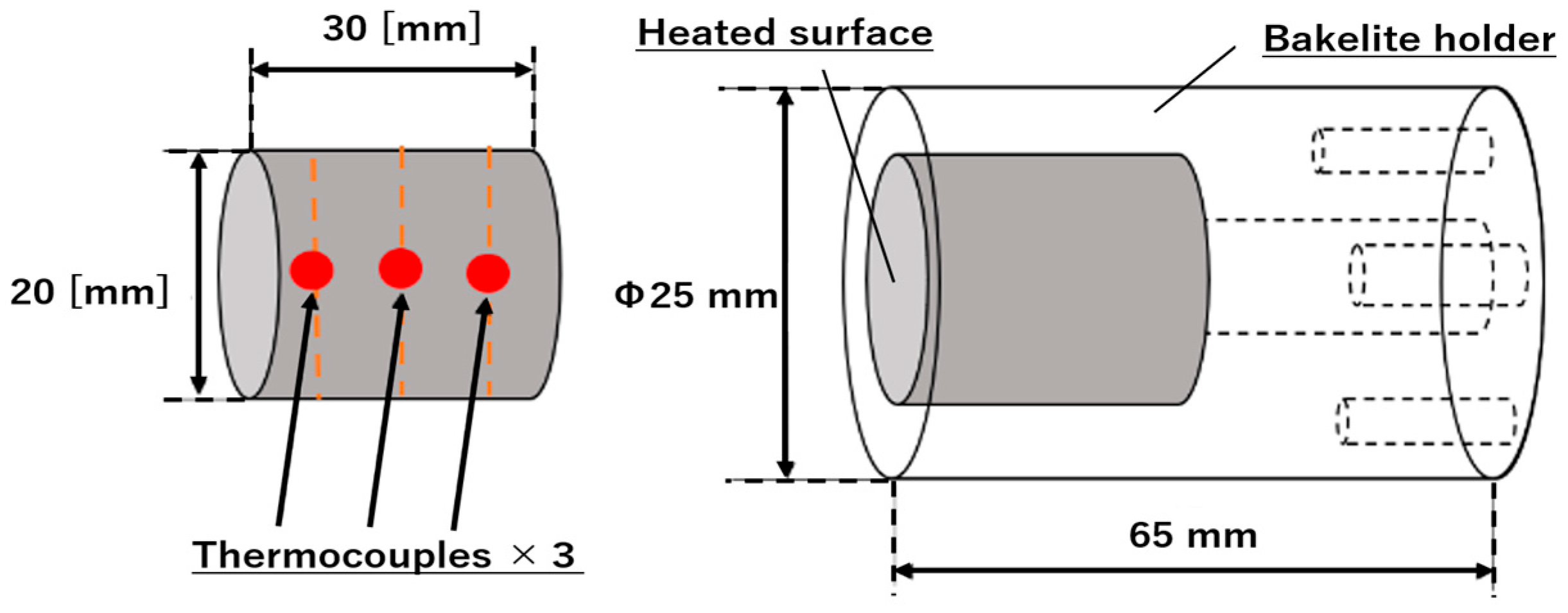
2.2. Thermal Conductivity Measurement of LATS/PEEK
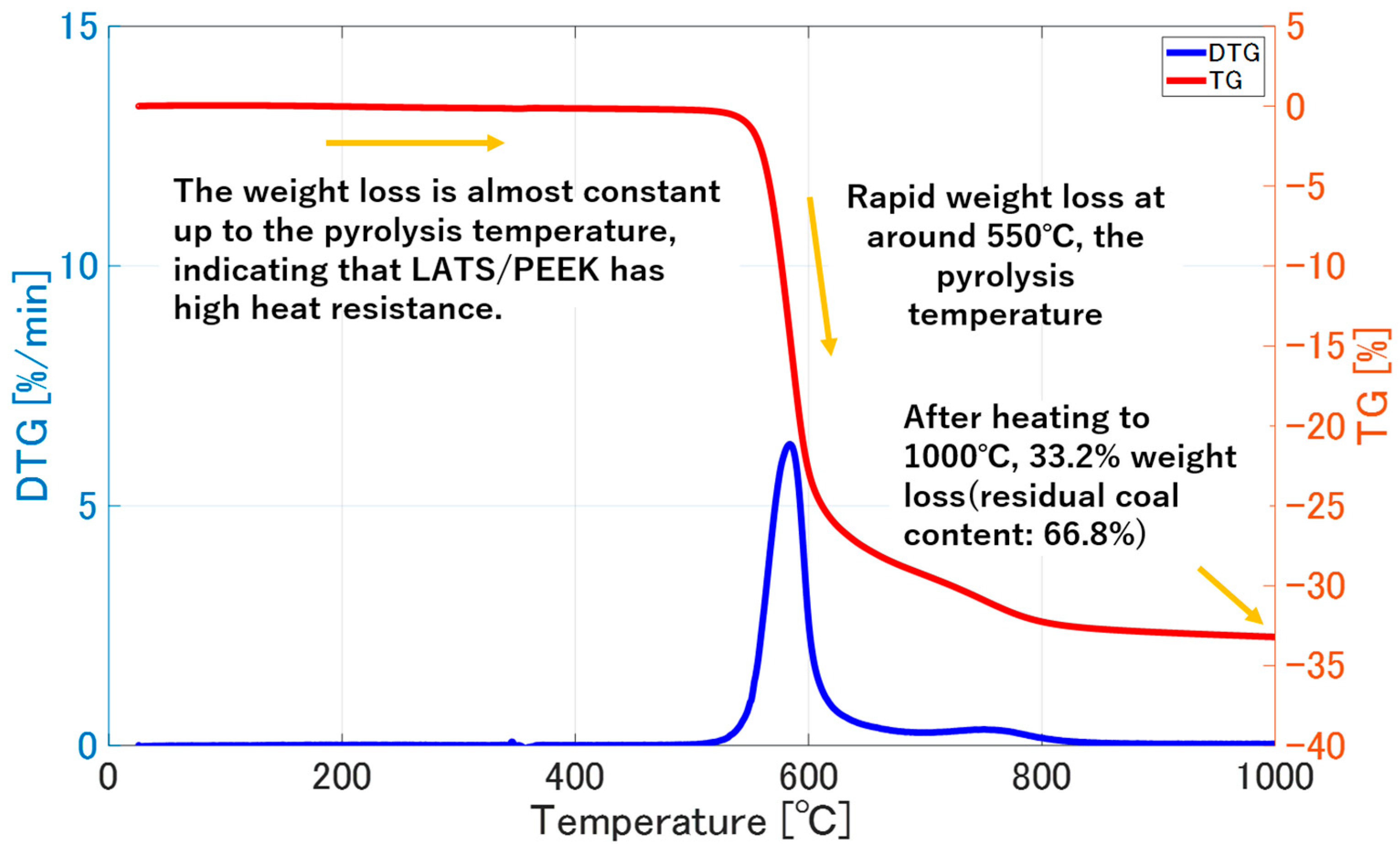
2.3. Thermal Weight Loss and Thermal Expansion Behavior of LATS/PEEK
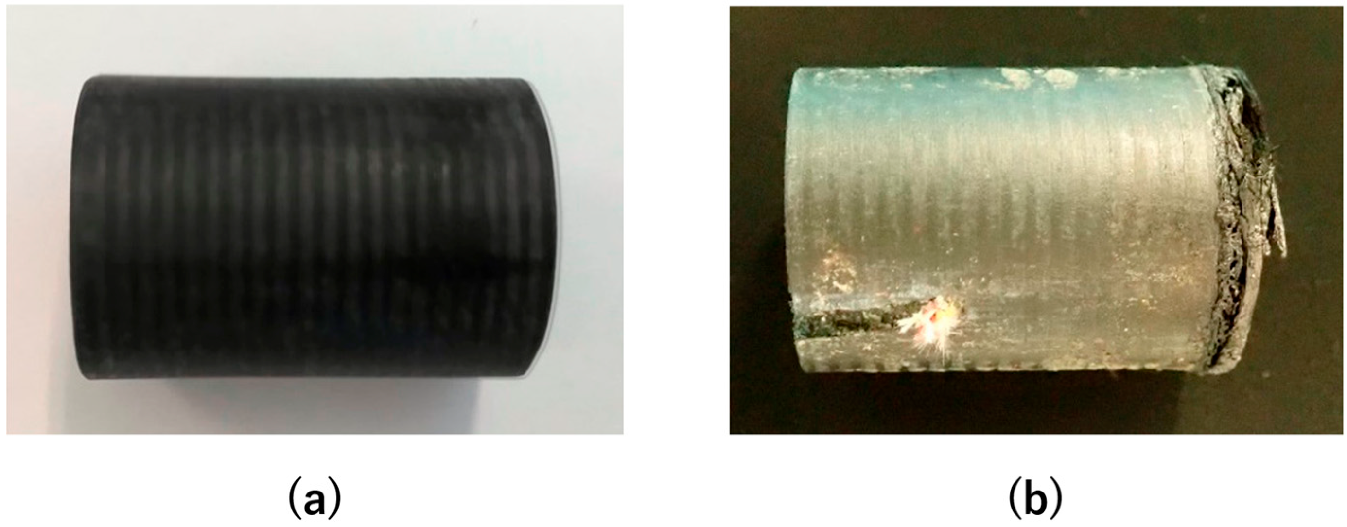
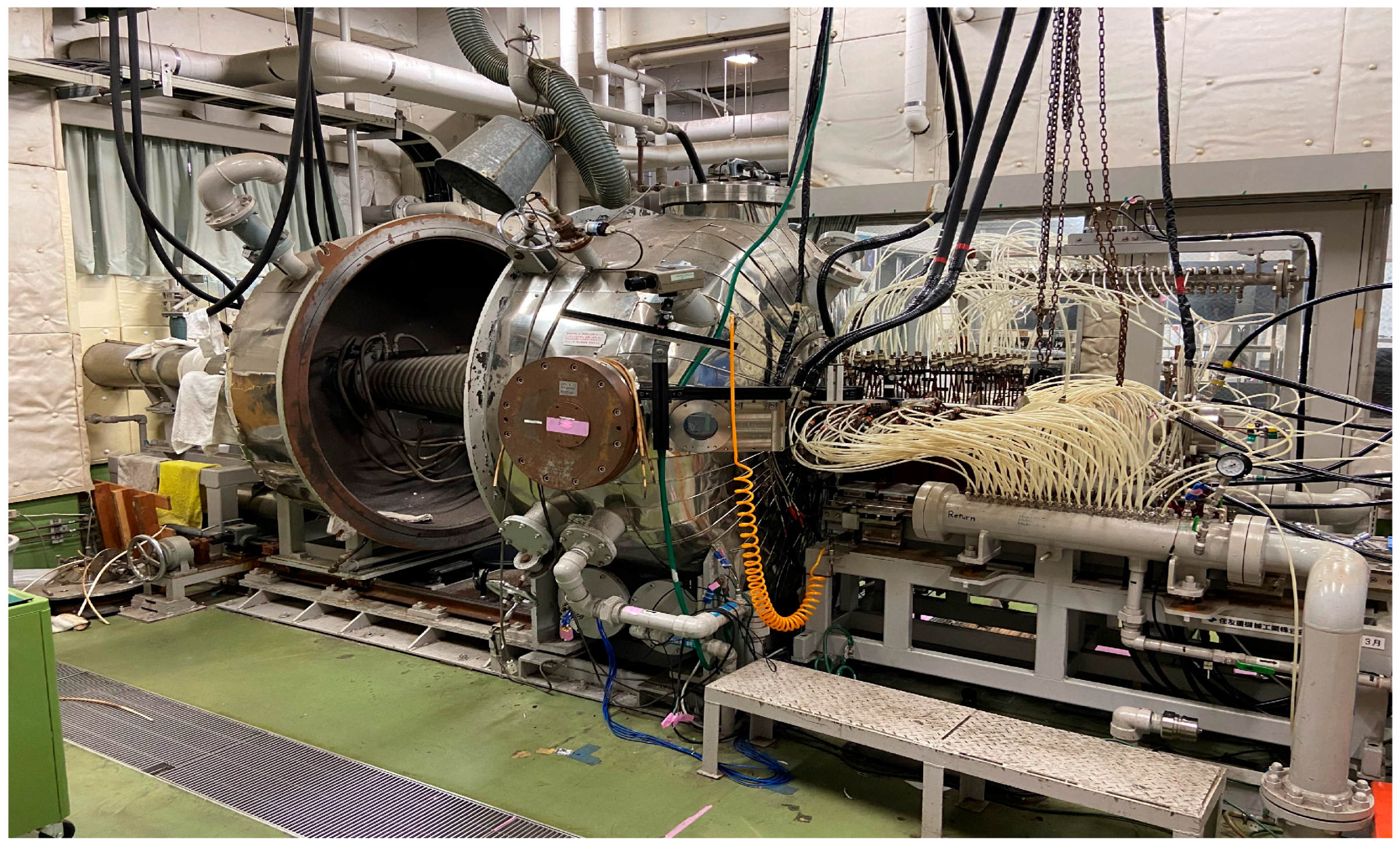
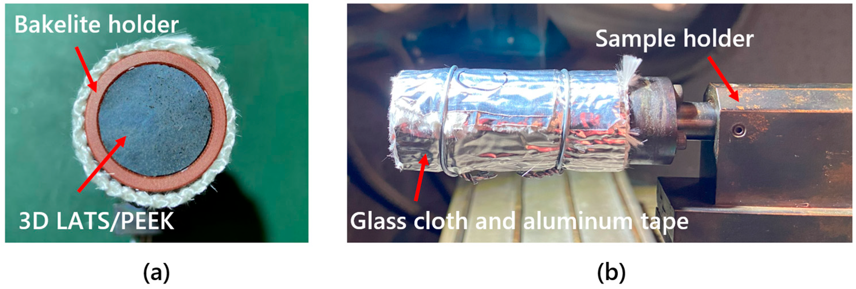
2.4. Deformation Behavior of LATS/PEEK in Arc-Heated Wind Tunnel Test
- Type A: 3D LATS/PEEK (density of 300–400 kg/m3)
- Type B: 3D LATS/PEEK (density of 500–600 kg/m3)
- Type C: 3D LATS/PEEK (density of 600–900 kg/m3)
- Type D: 3D LATS/Phenol (density of 800–900 kg/m3)
3. Results
3.1. Thermal Conductivity Measurement of LATS/PEEK
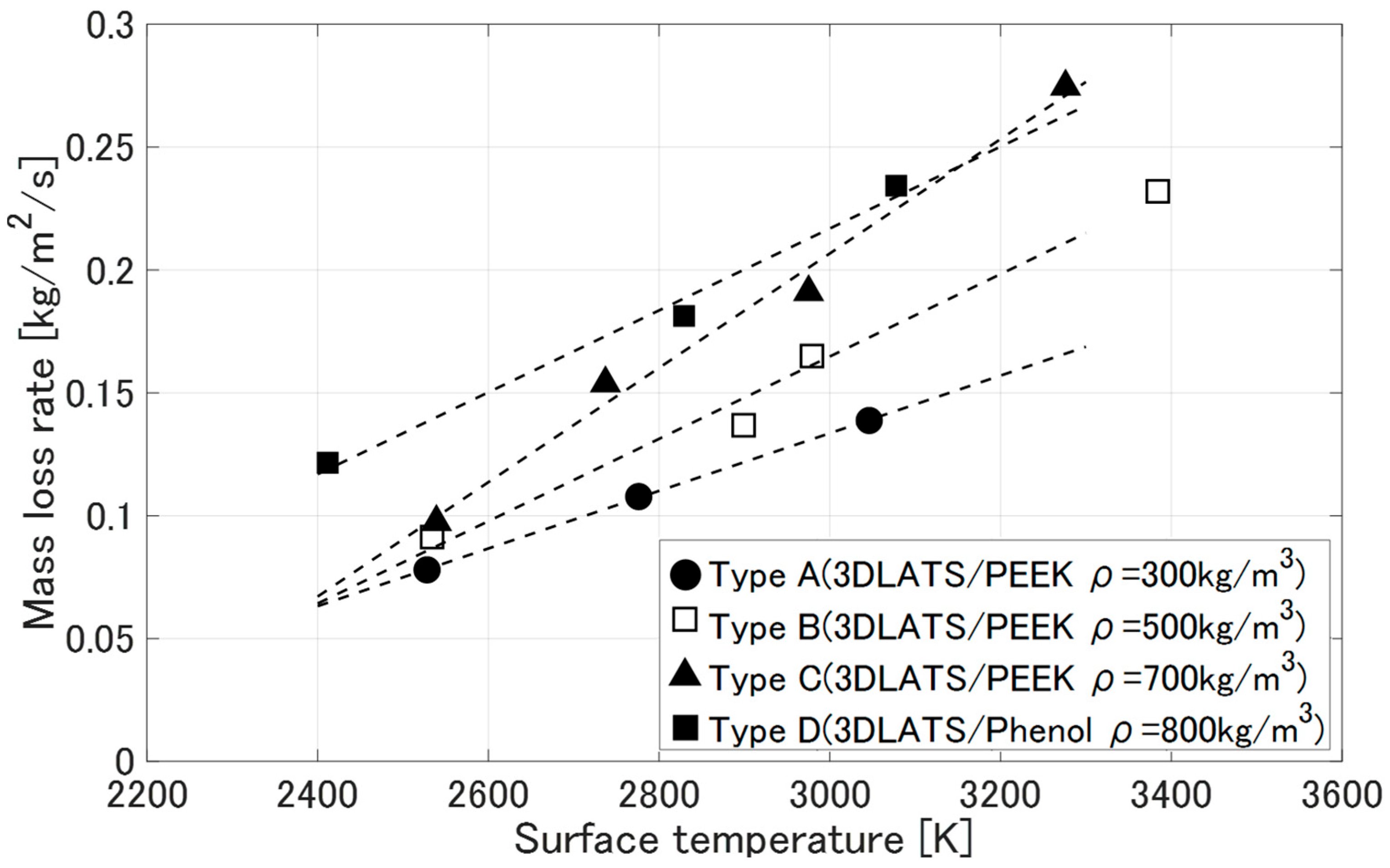
3.2. Thermal Weight Loss and Thermal Expansion Behavior of LATS/PEEK
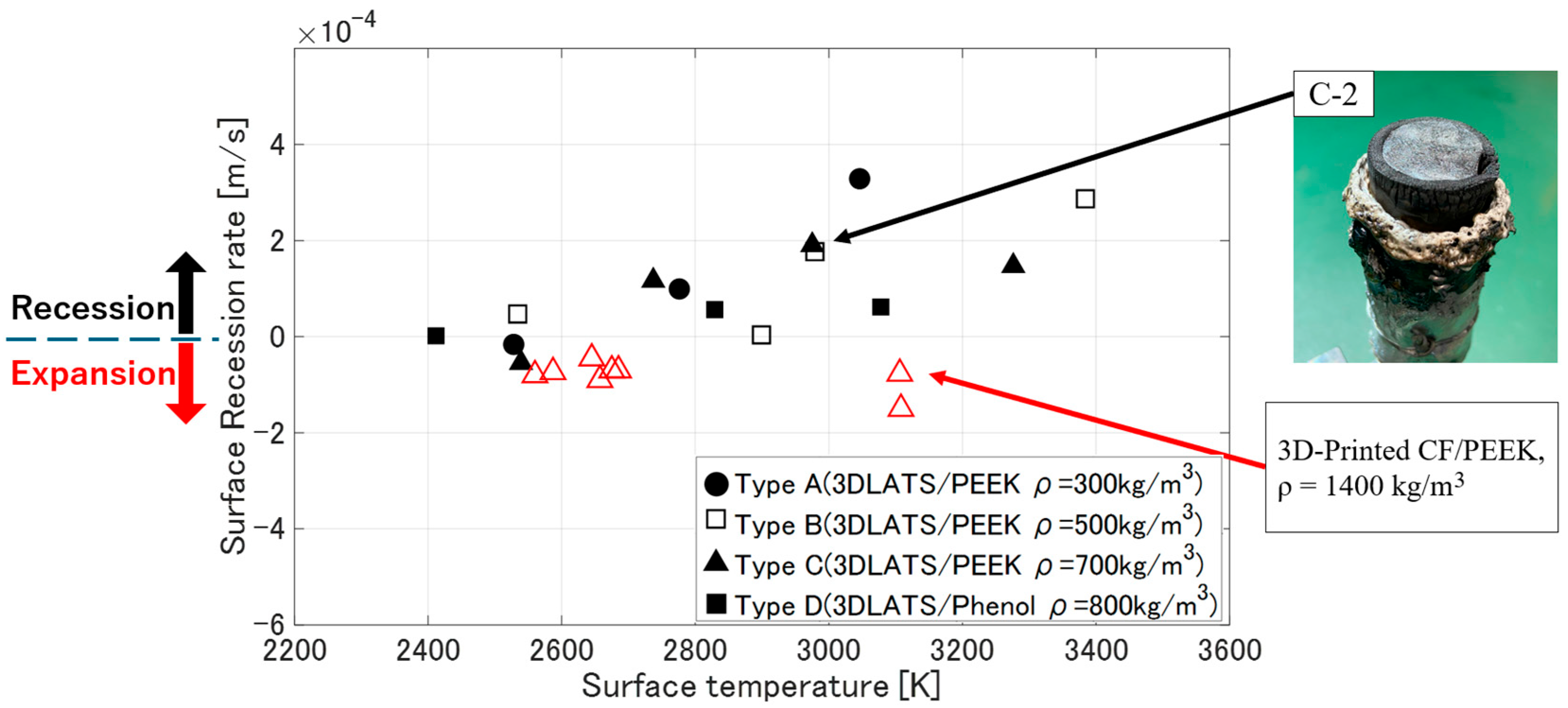
3.3. Deformation Behavior of LATS/PEEK in Arc-Heated Wind Tunnel Test
- Mass loss rate [kg/m2/s]
- Surface recession rate [m/s]
4. Discussion
4.1. Thermal Conductivity Measurement of LATS/PEEK
4.2. Thermal Weight Loss and Thermal Expansion Behavior of LATS/PEEK
4.3. Deformation Behavior of LATS/PEEK in Arc-Heated Wind Tunnel Test
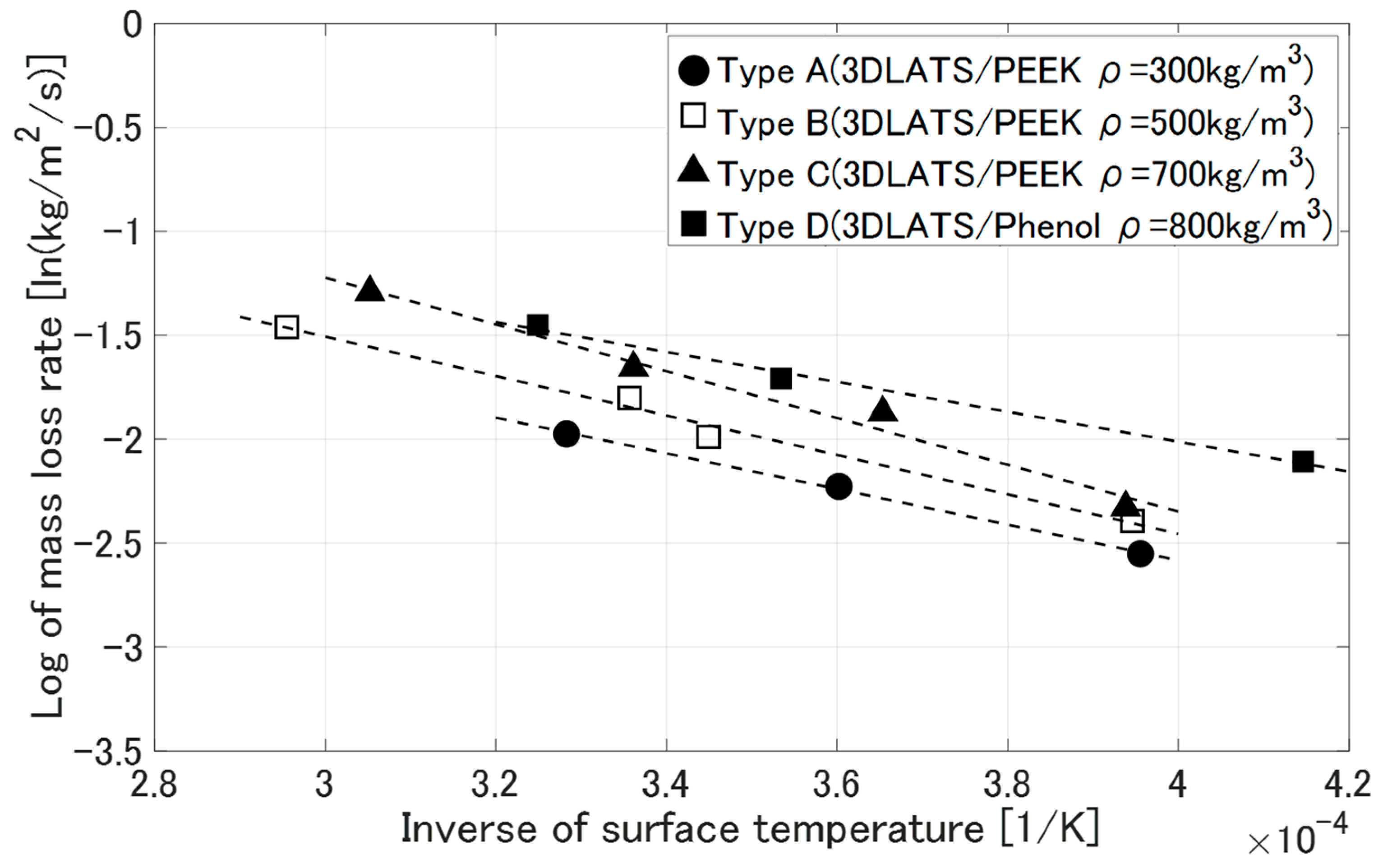
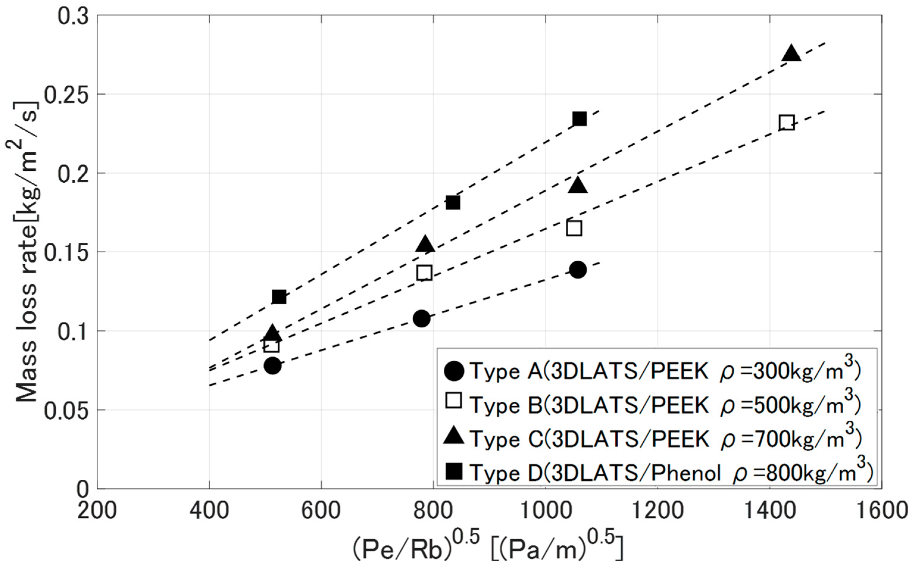
4.4. Thermo-Chemical Loss Characteristics of LATS/PEEK in Arc-Heated Wind Tunnel Tests
5. Conclusions
Author Contributions
Funding
Data Availability Statement
Acknowledgments
Conflicts of Interest
References
- Okuyama, K.; Rodriguez Leon, R.A.; Fajardo Tapia, I.; Ten-Koh 2 Team. Completion of the Development of Ten-Koh 2 Spacecraft. In Proceedings of the 33rd International Symposium on Space Technology and Science, Kurume, Japan, 6–9 June 2023. [Google Scholar]
- Ito, N.; Sasaki, H. Development Status of New Space Station Transfer Vehicle (HTV-X), Council for Science and Technology, Research Planning and Evaluation Subcommittee, Space Development and Utilization Subcommittee. 2021. Available online: https://www.mext.go.jp/content/20210209-mxt_uchukai01-000012798_10.pdf (accessed on 25 February 2025). (In Japanese).
- Nishihara, K.; Okuyama, K.; Rodriguez, R.; Fajardo, I. The Thermo-Mechanical Properties of Carbon-Fiber-Reinforced Polymer Composites Exposed to a Low Earth Orbit Environment. Aerospace 2021, 11, 201. [Google Scholar] [CrossRef]
- Okuyama, K.; Yoshikawa, K.; Oue, C. A Simple Method for Identifying the Natural Frequency of a Micro Satellite with a Primary Structure Made of Aluminum Alloy. Aerospace 2021, 11, 436. [Google Scholar]
- Campbell, F.C. Chapter 5—Ply Collation: A Major Cost Driver. In Manufacturing Processes for Advanced Composites; Campbell, F.C., Ed.; Elsevier Science: Amsterdam, The Netherlands, 2004; pp. 131–173. [Google Scholar]
- Campbell, F.C. Chapter 10—Thermoplastic Composites: An Unfulfilled Promise. In Manufacturing Processes for Advanced Composites; Campbell, F.C., Ed.; Elsevier Science: Amsterdam, The Netherlands, 2004; pp. 357–397. [Google Scholar]
- Diaz, J.; Rubio, L. Developments to Manufacture Structural Aeronautical Parts in Carbon Fiber Reinforced Thermoplastic Materials. J. Mater. Process. Technol. 2003, 143–144, 342–346. [Google Scholar] [CrossRef]
- Matsuzaki, R. Next Generation Molding Technology: Continuous Carbon Fiber 3D Printing. In The Future of Carbon Fibers and Carbon Fiber Composites; Tokyo University of Science: Tokyo, Japan, 2018; Chapter 5, Section 5.2. [Google Scholar]
- Kazuhiko, Y. Research and Development on Advanced Sample Return Capsule for Future Deep Space Exploration. In Proceedings of the 67th Space Sciences and Technology Conference, 1H11, Toyama, Japan, 17–20 October 2023. [Google Scholar]
- Caldwell, A.; Feldman, J. Reusable TPS Past, Present, & Future, Entry Systems and Technology Division Ames Research Center, NASA, June 2023. Available online: https://ntrs.nasa.gov/api/citations/20230009259/downloads/EDL%20Seminar%20-%20Reusable%20TPS%20Past%20Present%20and%20Future%20v4.0.pdf (accessed on 5 December 2023).
- Parcero, K.; Witkowski, A.; Davies, C. Planetary Mission Entry Vehicles, Quick Reference Guide, Ver. 4.1, SP-20230010341, NASA. Available online: https://www.nasa.gov/wp-content/uploads/2023/08/final-planetary-mission-entry-vehicles-quick-reference-guide-v4.1-.pdf (accessed on 5 December 2023).
- Yamada, T.; Abe, T. Plasma Phenomena and Surrounding Effects During the Earth Atmospheric Reentry of the Hayabusa Capsule. J. Plasma Fusion Res. 2006, 82, 368–374. [Google Scholar]
- Kubota, H.; Suzuki, K.; Watanuki, T. Thermogas Dynamics of Spacecraft; University of Tokyo Press: Tokyo, Japan, 2002; pp. 97–156. [Google Scholar]
- Okuyama, K.; Zako, M. A Study on Recession Characteristics of Completely Carbonized CFRP. Aerosp. Technol. Jpn. 2004, 3, 35–43. (In Japanese) [Google Scholar]
- Okuyama, K.; Kato, S.; Yamada, T.; Zako, M. Oxidation Characteristics of the Carbonized CFRP under the Air Environments. TANSO 2004, 213, 128–133. (In Japanese) [Google Scholar]
- Okuyama, K.; Kato, S.; Yamada, T. Thermo-Chemical Recession Characteristics of CFRP in an Earth Atmospheric Re-entry Environment. TANSO 2005, 219, 232–237. (In Japanese) [Google Scholar]
- Abdullah, F.; Okuyama, K.; Morimitsu, A.; Yamagata, N. Effects of Thermal Cycle and Ultraviolet Radiation on 3D Printed Carbon Fiber/Polyether Ether Ketone Ablator. Aerospace 2020, 7, 95. [Google Scholar] [CrossRef]
- Tran, H.; Johnson, C.; Rasky, D.; Hui, F.; Chen, Y.K.; Hsu, M. Phenolic Impregnated Carbon Ablators (PICA) for Discovery Missions. In Proceedings of the 31st AIAA Thermophysics Conference, New Orleans, LA, USA, 17–20 June 1996; AIAA Paper 96-1911. [Google Scholar]
- Tran, H.; Johnson, C.; Rasky, D.; Hui, F.; Hsu, M.; Chen, T.; Chen, Y.K.; Paragas, D.; Kobayashi, L. Phenolic Impregnated Carbon Ablators (PICA) for Discovery Missions, NASA TM 110440; NASA: Washington, DC, USA, 1997. [Google Scholar]
- Desai, P.N.; Mitcheltree, R.A.; Cheatwood, F.M. Entry Dispersion Analysis for the Stardust Comet Sample Return Capsule. In Proceedings of the GNC, AFM, and MST Conference and Exhibit, New Orleans, LA, USA, 11–13 August 1997; AIAA Paper 97-3812. [Google Scholar]
- Willcockson, W.H. Stardust Sample Return Capsule Design Experience. J. Spacecr. Rocket. 1999, 36, 470–474. [Google Scholar] [CrossRef]
- Okuyama, K.; Kato, S.; Ohya, H. Thermochemical Performance of a Lightweight Charring Carbon Fiber Reinforced Plastic. J. Jpn. Soc. Aeronaut. Space Sci. 2013, 56, 159–169. (In Japanese) [Google Scholar]
- Kobayashi, Y.; Sakai, T.; Okuyama, K.; Suzuki, T.; Fujita, K.; Kato, S. An Experimental Study on Thermal Response of Low Density Carbon-Phenolic Ablators. In Proceedings of the 47th AIAA Aerospace Sciences Meeting Including the New Horizons Forum and Aerospace Exposition, Orlando, FL, USA, 5–8 January 2009; AIAA Paper 2009-1587. [Google Scholar]
- Suzuki, T.; Fujita, K.; Sakai, T.; Okuyama, K.; Kato, S.; Nishio, S. Evaluation of Prediction Accuracy of Thermal Response of Ablator under Arcjet Flow Conditions. In Proceedings of the 10th AIAA/ASME Joint Thermophysics and Heat Transfer Conference, Chicago, IL, USA, 28 June–1 July 2010; AIAA Paper 2010-4787. [Google Scholar]
- Sakai, T.; Inoue, T.; Kuribayashi, M.; Okuyama, K.; Suzuki, T.; Fujita, K.; Kato, S.; Nishio, S. Post-Test Sample Analysis of Low Density Ablators Using Arcjet. Trans. Jpn. Soc. Aeronaut. Space Sci. Aerosp. Technol. 2012, 10, 65–71. [Google Scholar] [CrossRef] [PubMed]
- Suzuki, T.; Fujita, K.; Sakai, T.; Okuyama, K.; Kato, S.; Nishio, S. Thermal Response Analysis of Low Density CFRP Ablator. Trans. Jpn. Soc. Aeronaut. Space Sci. Aerosp. Technol. 2012, 10, 21–30. [Google Scholar] [CrossRef] [PubMed]
- Kato, S.; Okuyama, K.; Gibo, K.; Miyagi, T.; Suzuki, T.; Fujita, K.; Sakai, T.; Nishio, S.; Watanabe, A. Thermal Response Simulation of Ultra-Light Weight Phenolic Carbon Ablator by the Use of the Ablation Analysis Code. Trans. JSASS Aerosp. Technol. Jpn. 2012, 10, Pe31–Pe39. [Google Scholar] [CrossRef] [PubMed]
- Johnson, S.M. Thermal Protection Materials and Systems: Past, Present, and Future. In Proceedings of the Missouri University of Science and Technology, Rolla, MO, USA, 4 April 2013. [Google Scholar]
- Okuyama, K.; Kato, S.; Yamada, T. USERS REV Capsule Research, Development and a Post-Flight Analysis; JAXA Research and Development Report; JAXA-RR-04-045; JAXA: Tokyo, Japan, 2005; pp. 55–76. (In Japanese) [Google Scholar]
- Schneider, P.J.; Dolton, T.A.; Reed, G.W. Mechanical Erosion of Charring Ablators in Ground-Test and Re-entry Environments. AIAA J. 1968, 6, 64–72. [Google Scholar]
- Potts, R.L. Application of Integral Methods to Ablation Charring Erosion, A Review. J. Spacecr. Rocket. 1995, 32, 200–209. [Google Scholar]
- Shimoda, T.; Yamada, K. Status and Development of Arc Wind Tunnel in JAXA/ISAS. Aerosp. Technol. Jpn. 2015, 315–320. Available online: https://www.jstage.jst.go.jp/article/kjsass/63/10/63_KJ00010078682/_pdf (accessed on 25 February 2025). (In Japanese).
- Patel, P.; Hull, T.R.; McCade, R.W.; Flath, D.; Grasmeder, J.; Percy, M. Mechanism of Thermal Decomposition of Poly(Ether Ether Ketone)(PEEK) From a Review of Decomposition Studies. Polym. Degrad. Stab. 2010, 95, 709–718. [Google Scholar] [CrossRef]
- Suzuki, T.; Sawada, K.; Yamada, T.; Inatani, Y. Thermal Response of Ablative Test Piece in Arc-Heated Wind Tunnel. In Proceedings of the 42nd AIAA Aerospace Sciences Meeting, Reno, NV, USA, 5–8 January 2004; AIAA 2004-341. [Google Scholar]
- Park, C. Stagnation-Point Ablation of Carbonaceous Flat Disks—Part II: Experiment. AIAA J. 1983, 21, 1748–1754. [Google Scholar] [CrossRef]
- Koyanagi, J.; Fukuda, Y.; Yoneyama, S.; Hirai, K.; Yoshimura, A.; Aoki, T.; Ogasawara, T. Local Out-of-Plane Deformation of CFRP Ablator Subjected to Rapid Heating. J. Jpn. Soc. Compos. Mater. 2016, 42, 146–152. [Google Scholar]
- Peters, E. NASA Identifies Cause of Artemis I Orion Heat Shield Char Loss. 5 December 2024. Available online: https://www.nasa.gov/missions/artemis/nasa-identifies-cause-of-artemis-i-orion-heat-shield-char-loss/ (accessed on 5 December 2024).
- Metzger, J.W.; Engel, M.J.; Diaconis, N.S. Oxidation and Sublimation of Graphite. AIAA J. 1967, 5, 425–431. [Google Scholar]
- Potts, R.L. Hybrid Integral/Quasi-Steady Solution of Charring Ablation. In Proceedings of the 5th Joint Thermophysics and Heat Transfer Conference, Seattle, WA, USA, 18–20 June 1990. [Google Scholar]


| Type | Specimens | Conditions | |||||
|---|---|---|---|---|---|---|---|
| No. | Material | Density kg/m3 | Time [s] | Distance from Nozzle [mm] | Stagnation Pressure [kPa] | Heat Flux [MW/m2] | |
| A | A-1 | 3DLATS/PEEK | 332 | 20 | 75 | 27.2 | 8.24 |
| A-2 | 326 | 20 | 100 | 14.8 | 4.85 | ||
| A-3 | 352 | 20 | 150 | 6.30 | 1.99 | ||
| B | B-1 | 3DLATS/PEEK | 549 | 20 | 50 | 49.5 | 12.6 |
| B-2 | 542 | 20 | 75 | 27.2 | 8.24 | ||
| B-3 | 577 | 20 | 100 | 14.8 | 4.85 | ||
| B-4 | 592 | 20 | 150 | 6.30 | 1.99 | ||
| C | C-1 | 3DLATS/PEEK | 894 | 20 | 50 | 49.5 | 12.6 |
| C-2 | 674 | 20 | 75 | 27.2 | 8.24 | ||
| C-3 | 781 | 20 | 100 | 14.8 | 4.85 | ||
| C-4 | 727 | 20 | 150 | 6.30 | 1.99 | ||
| D | D-1 | 3DLATS/Phenol | 865 | 20 | 150 | 6.62 | 1.88 |
| D-2 | 843 | 20 | 100 | 16.9 | 4.78 | ||
| D-3 | 821 | 20 | 75 | 26.9 | 8.71 | ||
| Type | Material | Density [kg/m3] | A | B |
|---|---|---|---|---|
| X-1 | 2DLATS/Phenol [26] | 600 | 2.57 × 10⁻⁴ | 1.19 × 10⁻¹ |
| X-2 | 2DLATS/PEEK | 600 | 1.96 × 10⁻⁴ | 1.57 × 10⁻¹ |
| X-3 | 3DLATS/PEEK | 600 | 3.90 × 10⁻⁴ | 1.70 × 10⁻¹ |
| X-4 | 3DLATS/PEEK | 400 | 1.48 × 10⁻⁴ | 1.37 × 10⁻¹ |
Disclaimer/Publisher’s Note: The statements, opinions and data contained in all publications are solely those of the individual author(s) and contributor(s) and not of MDPI and/or the editor(s). MDPI and/or the editor(s) disclaim responsibility for any injury to people or property resulting from any ideas, methods, instructions or products referred to in the content. |
© 2025 by the authors. Licensee MDPI, Basel, Switzerland. This article is an open access article distributed under the terms and conditions of the Creative Commons Attribution (CC BY) license (https://creativecommons.org/licenses/by/4.0/).
Share and Cite
Ohkage, M.; Okuyama, K.-i.; Hori, S.; Ishida, T. Heat Shield Properties of Lightweight Ablator Series for Transfer Vehicle Systems with Different Laminated Structures Under High Enthalpy Flow Environments. Aerospace 2025, 12, 281. https://doi.org/10.3390/aerospace12040281
Ohkage M, Okuyama K-i, Hori S, Ishida T. Heat Shield Properties of Lightweight Ablator Series for Transfer Vehicle Systems with Different Laminated Structures Under High Enthalpy Flow Environments. Aerospace. 2025; 12(4):281. https://doi.org/10.3390/aerospace12040281
Chicago/Turabian StyleOhkage, Masayuki, Kei-ichi Okuyama, Soichiro Hori, and Tsumugi Ishida. 2025. "Heat Shield Properties of Lightweight Ablator Series for Transfer Vehicle Systems with Different Laminated Structures Under High Enthalpy Flow Environments" Aerospace 12, no. 4: 281. https://doi.org/10.3390/aerospace12040281
APA StyleOhkage, M., Okuyama, K.-i., Hori, S., & Ishida, T. (2025). Heat Shield Properties of Lightweight Ablator Series for Transfer Vehicle Systems with Different Laminated Structures Under High Enthalpy Flow Environments. Aerospace, 12(4), 281. https://doi.org/10.3390/aerospace12040281