

Adaptive Fault-Tolerant Tracking Control with Global Prescribed Performance Function for the Twin Otter Aircraft System


Abstract
1. Introduction
- 1.
- Elimination of initial tracking error constraints: Unlike conventional PPC approaches [8,9,10,11,14] that restrict initial error values, the proposed method employs a novel time-varying prescribed performance boundary function, removing these constraints and significantly enhancing control system adaptability during unpredictable scenarios, such as sudden system re-engagements or abrupt reference signal variations.
- 2.
- Real-time adaptive error boundary adjustment with simplified structure: In contrast to existing adaptive boundary adjustment methods [15,22], this study introduces an improved monitoring function that dynamically adjusts performance boundaries based on real-time fault detection, while simultaneously eliminating the need for error normalization and complex transformation processes. This structural simplification greatly enhances real-world implementation feasibility and robustness against actuator faults and disturbances.
- 3.
- Guaranteed fixed-time convergence and robustness under faults: By integrating fixed-time convergence theory into the prescribed performance framework, this paper rigorously guarantees fixed-time convergence of the tracking error into a small neighborhood of the origin. This theoretical advancement significantly improves both transient and steady-state robustness, enhancing overall safety and reliability in aviation applications, especially considering actuator faults and external disturbances.
2. Aircraft System and Problem Formulation
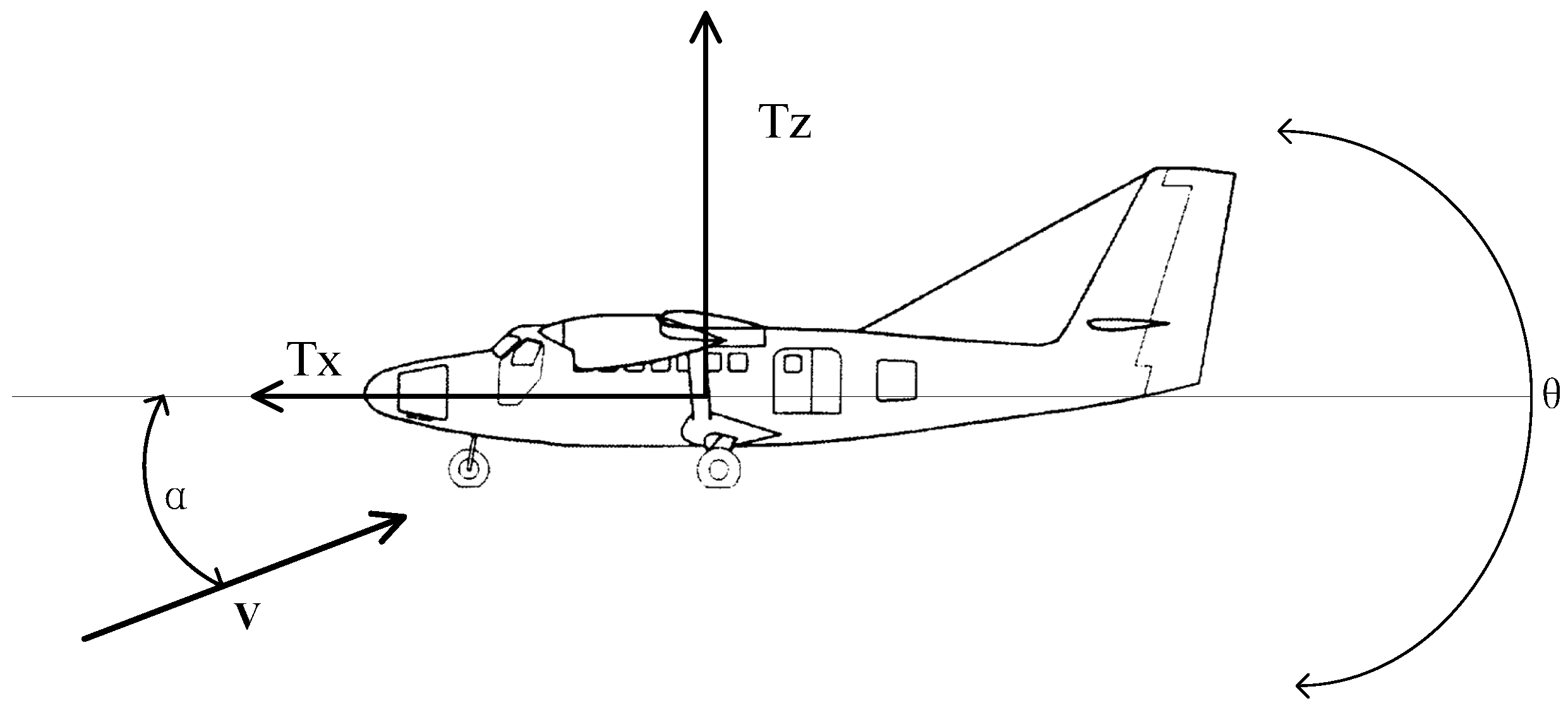
2.1. Overview of the Twin Otter Aircraft
2.2. Problem Formulation and System Modeling
3. Design and Analysis of an Adaptive Controller with Prescribed Performance and Restricted Boundaries
3.1. Prescribed Performance of the Tracking Error
- 1.
- and are strictly decreasing functions.
- 2.
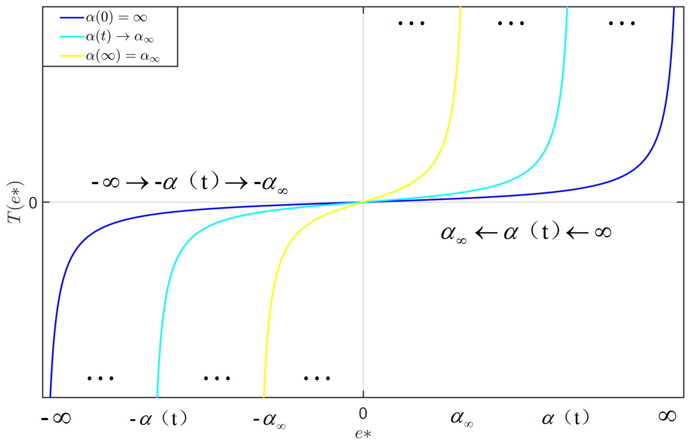
- 1.
- is monotonically increasing within its domain and possesses an inverse function, given by .
- 2.
- The function is bounded as follows: .
- 3.
- The asymptotic limits satisfy
3.2. Boundary Setting for System States
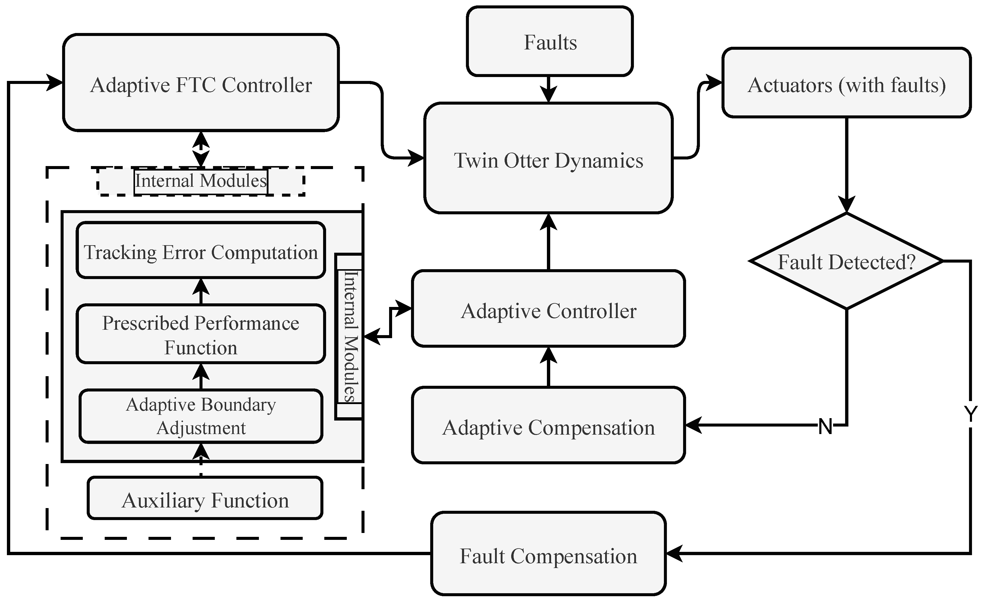
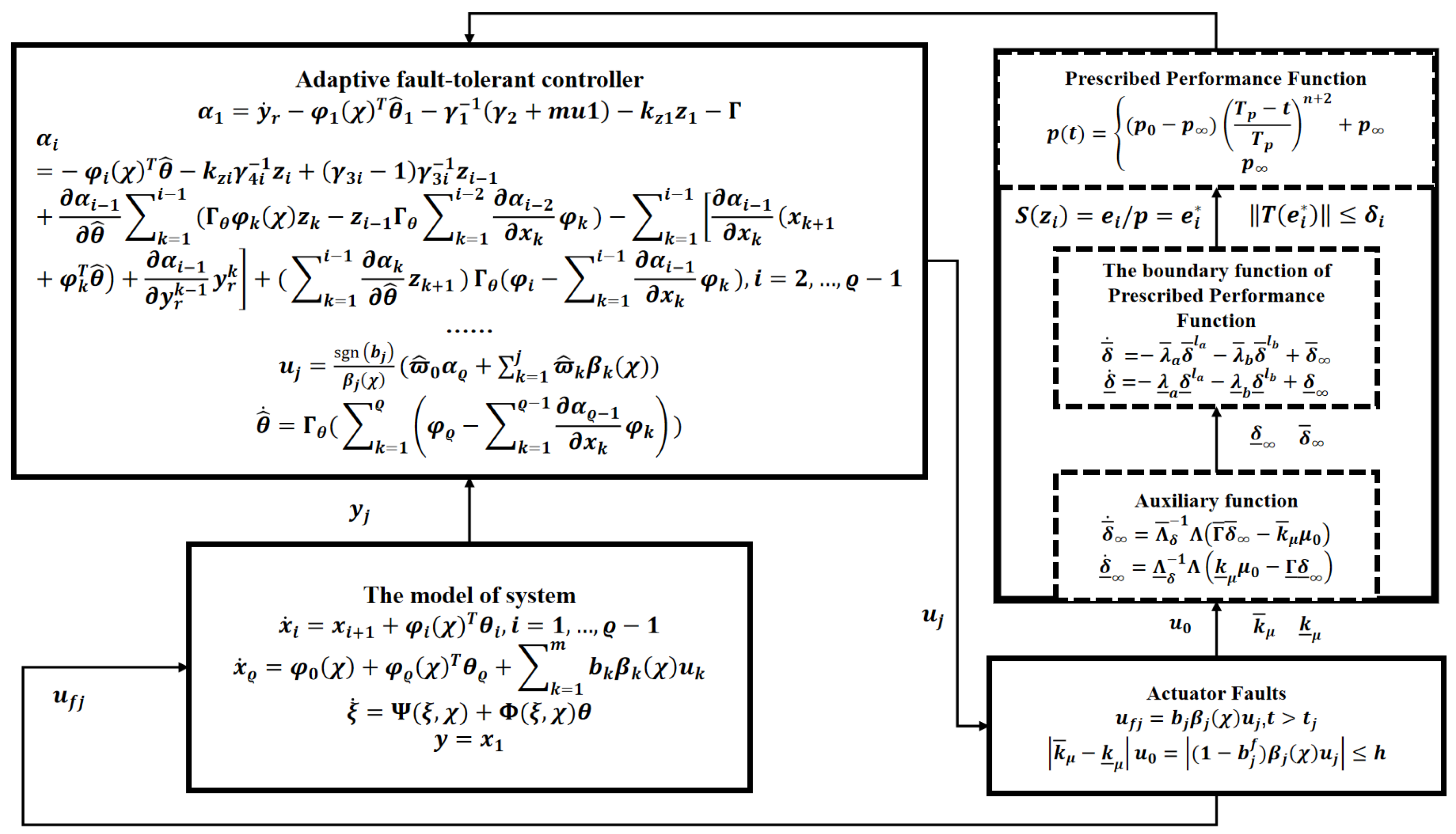
3.3. Adaptive Fault-Tolerant Control with Prescribed Performance Functions
- Auxiliary Function: Generated based on real-time fault information, auxiliary functions simultaneously adjust the bounds of the prescribed performance functions to compensate for actuator faults.
- Adaptive Boundary Adjustment: This feature dynamically modifies error bounds in response to auxiliary function outputs, ensuring system stability under varying fault conditions.
- Prescribed Performance Function: This function stablishes transient and steady-state performance constraints to regulate tracking errors within predefined limits.
- Tracking Error Computation: This feature computes the deviation between the desired trajectory and the actual response y, serving as the basis for adaptive control law design.
4. Adaptive Fault-Tolerant Controller Design and Analysis
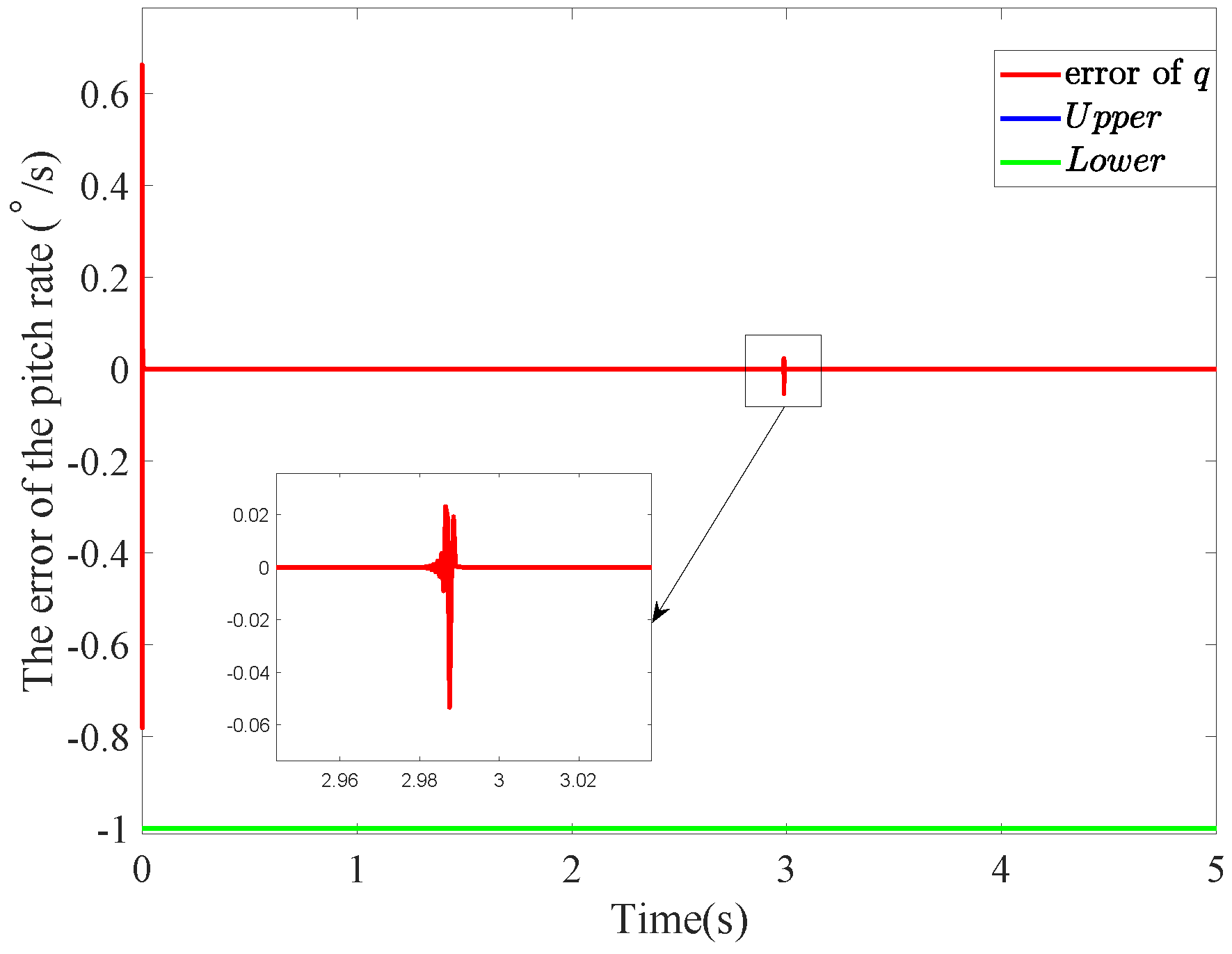
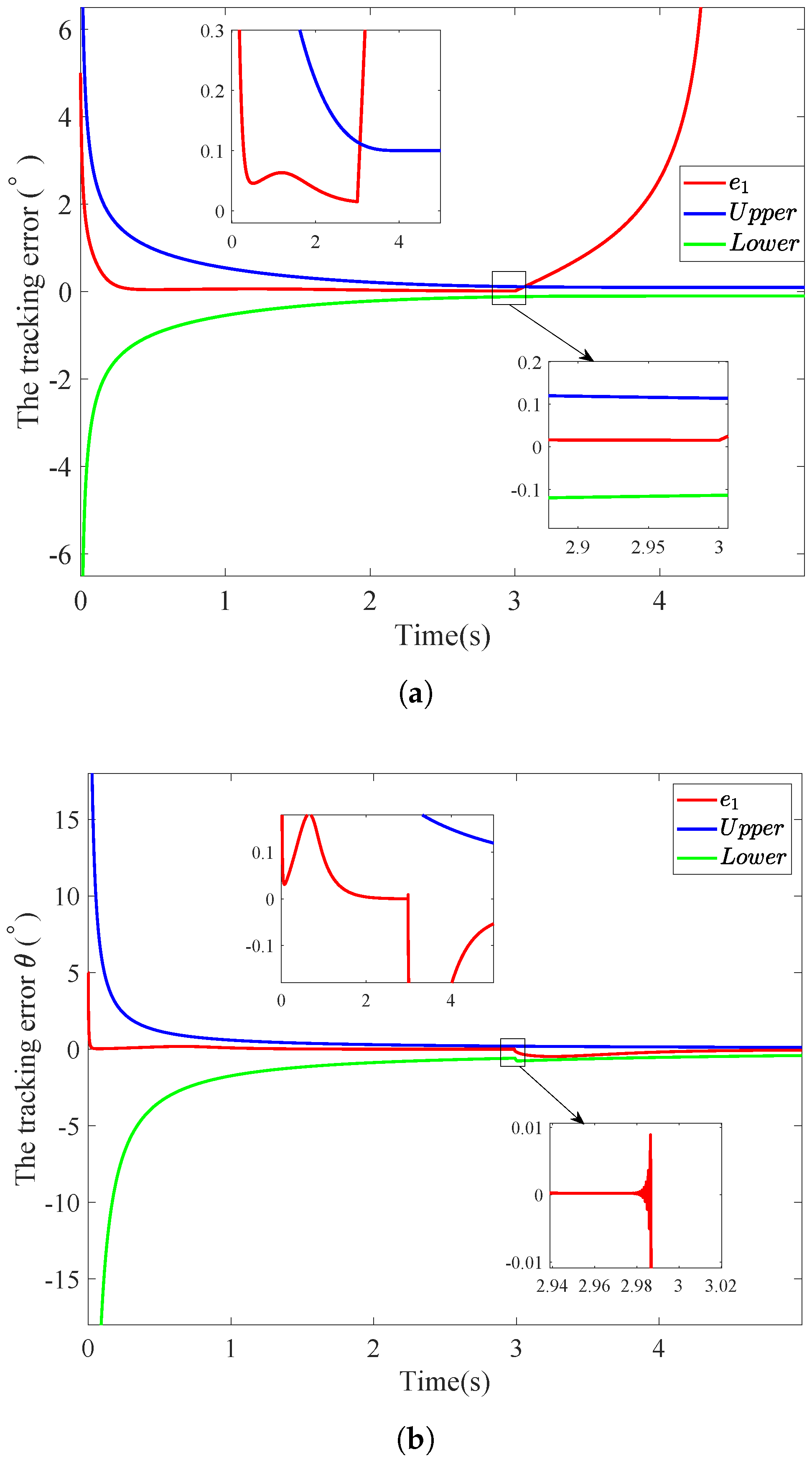
5. Simulation
- Initial estimated parameter vector:
- Adaptation gain matrix:
- Initial compensation parameter:
- Adaptation gains for fault compensation:
- Controller gains:
- Parameters of the prescribed performance function : , ,
- Boundary values for transformed tracking error:
- Boundary function parameters: , ,
- Upper boundary function parameters: , ,
- Lower boundary function parameters: , ,
6. Conclusions
Author Contributions
Funding
Data Availability Statement
Conflicts of Interest
References
- Cao, Y.H.; Tan, W.Y.; Sun, Y. The Effects of Icing on Aircraft Longitudinal Aerodynamic Characteristics. Mathematics 2020, 8, 1171. [Google Scholar] [CrossRef]
- Bechlioulis, C.P.; Rovithakis, G.A. Decentralized Robust Synchronization of Unknown High Order Nonlinear Multi-Agent Systems With Prescribed Transient and Steady State Performance. IEEE Trans. Autom. Control. 2017, 62, 123–134. [Google Scholar] [CrossRef]
- Ouyang, H.P.; Lin, Y. Adaptive fault-tolerant control for actuator failures: A switching strategy. Automatica 2017, 81, 87–95. [Google Scholar] [CrossRef]
- Zhang, J.X.; Yang, G.H. Prescribed Performance Fault-Tolerant Control of Uncertain Nonlinear Systems with Unknown Control Directions. IEEE Trans. Autom. Control. 2017, 62, 6529–6535. [Google Scholar] [CrossRef]
- Deng, X.F.; Huang, Y.Q. Position and Attitude Tracking Finite-Time Adaptive Control for a VTOL Aircraft Using Global Fast Terminal Sliding Mode Control. Mathematics 2023, 12, 2732. [Google Scholar] [CrossRef]
- Gao, X.; Zhang, J.X.; Hao, L. Fault-Tolerant Control of Pneumatic Continuum Manipulators Under Actuator Faults. IEEE Trans. Ind. Informatics 2021, 17, 8299–8307. [Google Scholar] [CrossRef]
- Huang, S.; Tan, K.K.; Xiao, M. Automated Fault Diagnosis and Accommodation Control for Mechanical Systems. IEEE/ASME Trans. Mechatronics 2015, 20, 155–165. [Google Scholar] [CrossRef]
- Bechlioulis, C.P.; Rovithakis, G.A. Robust Adaptive Control of Feedback Linearizable MIMO Nonlinear Systems with Prescribed Performance. IEEE Trans. Autom. Control. 2008, 53, 2090–2099. [Google Scholar] [CrossRef]
- Wu, Z.L.; Ye, J.C. Dynamic Event-Triggered Prescribed Performance Robust Control for Aggressive Quadrotor Flight. Aerospace 2024, 11, 301. [Google Scholar] [CrossRef]
- Dimanidis, S.; Bechlioulis, C.P.; Rovithakis, G.A. Output Feedback Approximation-Free Prescribed Performance Tracking Control for Uncertain MIMO Nonlinear Systems. IEEE Trans. Autom. Control. 2020, 65, 5058–5069. [Google Scholar] [CrossRef]
- Mai, G.; Wang, H.L. Nonlinear Extended State Observer and Prescribed Performance Fault-Tolerant Control of Quadrotor Unmanned Aerial Vehicles Against Compound Faults. Aerospace 2024, 11, 903. [Google Scholar] [CrossRef]
- Al-Dujaili, A.; Cocquempot, V.; Najjar, M.E.; Pereira, D.; Humaidi, A. Fault Diagnosis and Fault Tolerant Control for Linked Two-Wheel Drive Mobile Robots. In Mobile Robot: Motion Control and Path Planning; Springer International Publishing: Cham, Switzerland, 2023; pp. 403–437. [Google Scholar]
- Al-Dujaili, A.; Cocquempot, V.; Najjar, M.E.; Pereira, D.; Humaidi, A. Adaptive Fault-Tolerant Control Design for Multi-Linked Two-Wheel Drive Mobile Robots. In Mobile Robot: Motion Control and Path Planning; Springer International Publishing: Cham, Switzerland, 2023; pp. 283–329. [Google Scholar]
- Zhao, K.; Song, Y.D.; Chen, C.L. Adaptive Asymptotic Tracking with Global Performance for Nonlinear Systems with Unknown Control Directions. IEEE Trans. Autom. Control. 2022, 67, 1566–1573. [Google Scholar] [CrossRef]
- Ji, R.H.; Yang, B.; Ma, J.; Ge, S.S. Saturation-Tolerant Prescribed Control for a Class of MIMO Nonlinear Systems. IEEE Trans. Cybern. 2021, 52, 13012–13026. [Google Scholar] [CrossRef] [PubMed]
- Bhat, S.P.; Bernstein, D.S. Finite-Time Stability of Continuous Autonomous Systems. Soc. Ind. Appl. Math. 2000, 38, 751–766. [Google Scholar] [CrossRef]
- Polyakov, A. Nonlinear Feedback Design for Fixed-Time Stabilization of Linear Control Systems. IEEE Trans. Autom. Control. 2012, 57, 2106–2110. [Google Scholar] [CrossRef]
- Xia, J.; Zhang, J.; Sun, W.; Zhang, B. Finite-Time Adaptive Fuzzy Control for Nonlinear Systems with Full State Constraints. IEEE Trans. Syst. Man Cybern. Syst. 2019, 49, 1541–1548. [Google Scholar] [CrossRef]
- Li, H.; Lu, P.; Li, Z.W. Finite Time-Adaptive Full-State Quantitative Control of Quadrotor Aircraft and QDrone Experimental Platform Verification. Drones 2024, 8, 351. [Google Scholar] [CrossRef]
- Zhang, L.; Liu, H.; Tang, D. Adaptive Fixed-Time Fault-Tolerant Tracking Control and Its Application for Robot Manipulators. IEEE Trans. Ind. Electron. 2022, 69, 2956–2966. [Google Scholar] [CrossRef]
- Fu, M.Y.; Yu, L.L. Finite-time extended state observer-based distributed formation control for marine surface vehicles with input saturation and disturbances. Ocean. Eng. 2018, 159, 219–227. [Google Scholar] [CrossRef]
- Zhao, K.; Song, Y.D.; Ma, T.; He, L. Prescribed Performance Control of Uncertain Euler—Lagrange Systems Subject to Full-State Constraints. IEEE Trans. Neural Netw. Learn. Syst. 2018, 29, 3478–3489. [Google Scholar] [CrossRef]
- Yang, H.P.; Zhang, Z.Q. An Adaptive Control Scheme for Longitudinal Dynamics of A Twin Otter Aircraft. In Proceedings of the 2021 40th Chinese Control Conference (CCC), Shanghai, China, 26–28 July 2021; pp. 2275–2279. [Google Scholar] [CrossRef]
- Ouyang, H.P.; Zhou, E.B.; Wang, C.Q. Fault tolerant control for actuator failures with application to a twin otter aircraft. In Proceedings of the 2022 IEEE 17th Conference on Industrial Electronics and Applications (ICIEA), Chengdu, China, 16–19 December 2022; pp. 52–57. [Google Scholar] [CrossRef]
- Wu, Z.L.; Wu, B.Y.; Lv, B.; Cao, Y.H. Heavy rain effects on aircraft lateral/directional stability and control determined from numerical simulation data. Aerosp. Sci. Technol. 2018, 80, 472–481. [Google Scholar] [CrossRef]
- Wu, Z.L.; Cao, Y.H.; Ismail, M. Heavy rain effects on aircraft longitudinal stability and control determined from numerical simulation data. Proc. Inst. Mech. Eng. Part G J. Aerosp. Eng. 2015, 229, 1824–1842. [Google Scholar] [CrossRef]
- Su, X.H.; Su, Y.N.; Liu, P. Adaptive Fuzzy Control for Full-State Constraints Twin Otter Aircraft with Actuator Failure. In Proceedings of the 2023 IEEE International Conference on Unmanned Systems (ICUS), Hefei, China, 13–15 October 2023; pp. 263–268. [Google Scholar] [CrossRef]
- Wang, C.L.; Guo, L. Adaptive compensation for infinite number of actuator failures with an application to flight control. Int. J. Adapt. Control Signal Process. 2016, 30, 443–455. [Google Scholar] [CrossRef]
- Lv, B.Y.; Cao, Y.H.; Wu, Z.L. Numerical Simulation of Aerodynamic Penalties of the DHC-6 Twin Otter Aircraft in Heavy Rain. J. Aerosp. Eng. Mec. 2017, 1, 30–39. [Google Scholar] [CrossRef]
- Tang, X.D.; Tao, G. Adaptive actuator failure compensation for parametric strict feedback systems and an aircraft application. Automatica 2003, 39, 1975–1982. [Google Scholar] [CrossRef]
- Wang, W.; Wen, C.Y. Adaptive actuator failure compensation control of uncertain nonlinear systems with guaranteed transient performance. Automatica 2010, 46, 2082–2091. [Google Scholar] [CrossRef]
- Fu, M.Y.; Dong, L.J.; Xu, Y.J. A novel asymmetrical integral barrier Lyapunov function-based trajectory tracking control for hovercraft with multiple constraints. Ocean. Eng. 2022, 263, 112–132. [Google Scholar] [CrossRef]
- Fu, M.Y.; Zhang, T.; Ding, F.G. Safety-guaranteed adaptive neural motion control for a hovercraft with multiple constraints. Ocean. Eng. 2021, 220, 401–413. [Google Scholar] [CrossRef]
- Avram, R.C.; Zhang, X.; Muse, J. Quadrotor Actuator Fault Diagnosis and Accommodation Using Nonlinear Adaptive Estimators. IEEE Trans. Control. Syst. Technol. 2017, 25, 2219–2226. [Google Scholar] [CrossRef]


| Parameter | Symbol | Value |
|---|---|---|
| Aircraft mass | m | 4600 kg |
| Wing area | S | 39.2 m2 |
| Mean aerodynamic chord | c | 1.98 m |
| Pitch moment of inertia | kg·m2 | |
| Air density (5000 m) | 0.7377 kg/m3 | |
| Maximum takeoff weight | 5670 kg | |
| Maximum cruise speed | 337 km/h | |
| Stall speed (flaps down) | 107 km/h | |
| Maximum range | 1690 km | |
| Thrust (x-direction) | N | |
| Thrust (z-direction) | N |
| Coefficient Group | Symbol | Value |
|---|---|---|
| Longitudinal force coefficients | 0.39, 2.9 | |
| −0.0758, 0.0961 | ||
| Lateral force coefficients | −7.01, 4.11, −0.31 | |
| −0.23, −0.12 | ||
| Pitch moment coefficients | −0.87, −3.85, −0.01 | |
| −1.89, −0.63 | ||
| Control effectiveness factors | [0.6, 0.4] |
Disclaimer/Publisher’s Note: The statements, opinions and data contained in all publications are solely those of the individual author(s) and contributor(s) and not of MDPI and/or the editor(s). MDPI and/or the editor(s) disclaim responsibility for any injury to people or property resulting from any ideas, methods, instructions or products referred to in the content. |
© 2025 by the authors. Licensee MDPI, Basel, Switzerland. This article is an open access article distributed under the terms and conditions of the Creative Commons Attribution (CC BY) license (https://creativecommons.org/licenses/by/4.0/).
Share and Cite
Bai, D.; Lin, C.; Ding, Z.; Sun, L.; Xie, X.; Lai, C. Adaptive Fault-Tolerant Tracking Control with Global Prescribed Performance Function for the Twin Otter Aircraft System. Aerospace 2025, 12, 311. https://doi.org/10.3390/aerospace12040311
Bai D, Lin C, Ding Z, Sun L, Xie X, Lai C. Adaptive Fault-Tolerant Tracking Control with Global Prescribed Performance Function for the Twin Otter Aircraft System. Aerospace. 2025; 12(4):311. https://doi.org/10.3390/aerospace12040311
Chicago/Turabian StyleBai, Dan, Changliang Lin, Zhiwei Ding, Lin Sun, Xiaoming Xie, and Chonglang Lai. 2025. "Adaptive Fault-Tolerant Tracking Control with Global Prescribed Performance Function for the Twin Otter Aircraft System" Aerospace 12, no. 4: 311. https://doi.org/10.3390/aerospace12040311
APA StyleBai, D., Lin, C., Ding, Z., Sun, L., Xie, X., & Lai, C. (2025). Adaptive Fault-Tolerant Tracking Control with Global Prescribed Performance Function for the Twin Otter Aircraft System. Aerospace, 12(4), 311. https://doi.org/10.3390/aerospace12040311