Review

Progress and Development of Solid-Fuel Scramjet Technologies

1
Jiangxi Hongdu Aviation Industry Group Co., Ltd., Nanchang 330024, China
2
School of Energy and Power Engineering, Beihang University, Beijing 100191, China
3
Shen Yuan College, Beihang University, Beijing 100191, China
*
Author to whom correspondence should be addressed.
Aerospace 2025, 12(4), 351; https://doi.org/10.3390/aerospace12040351
Submission received: 16 March 2025 / Revised: 11 April 2025 / Accepted: 13 April 2025 / Published: 16 April 2025
(This article belongs to the Special Issue Innovation and Challenges in Hypersonic Propulsion)

Abstract

:
The solid-fuel scramjet has become a potential power device for hypersonic missiles in the future and has important military application prospects due to its advantages in gas flow regulation, flame stability, and blended combustion efficiency. This paper summarizes the research progress of three types of solid-fuel scramjet, including a large number of landmark numerical and experimental results. At the same time, the research progress of supersonic steady combustion and combustion enhancement technology, thermal protection technology, and the improvement of solid-fuel and combustion performance are reviewed. On this basis, the key technologies of the solid solid-fueled scramjet are summarized, and several internal scientific problems are summarized, such as the combustion organization strategy of the wide velocity domain solid rocket scramjet, efficient combustion chamber loading and thermal bulking technology, combustion instability, etc. Finally, some suggestions for the future development of the solid-fuel scramjet are put forward.

1. Introduction

With the rapid development of hypersonic flight technology, hypersonic aircraft have become the focus of international academic and military research because of their important military strategic value. One of the key challenges of the hypersonic vehicle is to locate an efficient and reliable power system, and scramjet, as an efficient propulsion technology, has become an ideal power choice for hypersonic vehicles because of its excellent performance in supersonic or even hypersonic flight conditions.
The scramjet can maintain a supersonic flow state in the combustion chamber under the condition of a flight Mach number greater than 5, thus obtaining a higher specific impulse, as shown in Figure 1. Compared with traditional turbojet and rocket engines, the scramjet not only has a higher specific impulse under hypersonic conditions, but also can achieve a longer flight in the atmosphere because of its simplified structure and no need to carry oxidizer. Therefore, the scramjet is widely regarded as the most promising power system for hypersonic vehicles.
In recent years, several countries and regions have conducted research on scramjet engines, achieving a series of important milestones. Successful flight tests of hypersonic vehicles, such as the U.S. X-43A [1,2,3] and X-51A [4,5,6], Russia’s CIAM-NASA [7], and Australia’s HyShot II [8,9,10], have demonstrated the feasibility of scramjet engines in hypersonic cruise, further advancing the engineering development of scramjet technology. These studies have not only provided valuable insights into the design and application of scramjet, but also laid the technological foundation for the future development of hypersonic weapon systems.
Compared to the liquid-fuel scramjet, the solid-fuel scramjet offers several advantages. The solid-fuel scramjet has a simple structure, low cost, ease of storage and transportation, and short response times, making it well suited to meet the operational demands of hypersonic weapon systems. This is particularly true for air-launched missiles and high-maneuverability warheads with limited space. The solid-fuel scramjet not only provides high energy density, but also enables intelligent collaborative networking and penetration tasks through the synergy of aerodynamic and self-powered actions. This is crucial for enhancing the strike effectiveness of hypersonic weapons.
Since the 1980s, research on the solid-fuel scramjet has made notable progress, but there is still a lack of comprehensive reviews in the existing literature regarding solid-fuel scramjet systems. With the continuous development of technology, the enhancement of performance, such as power output and combustion efficiency of solid-fuel scramjet engines, still faces numerous challenges. These challenges particularly include optimizing the energy density of solid fuels and improving combustion efficiency and the overall design of engine structures. Therefore, improving the comprehensive performance of solid-fuel scramjet engines remains one of the current hot topics in research.
This paper aims to provide an overview of the current research on the solid-fuel scramjet, with a focus on analyzing its key technologies and challenges.

2. Overall Configuration of the Solid-Fuel Scramjet

The development of the solid-fuel scramjet has evolved alongside advancements in hypersonic vehicle technology. Solid-fuel scramjet engines are mainly classified into three types based on the chronological order: the solid-fuel scramjet (SFSJ), solid ducted rocket scramjet (SRSJ), and solid dual-combustor scramjet (DMRJ). The SFSJ utilizes solid fuels that are adhered to the internal walls of the combustion chamber. The combustion occurs as the engine flies at hypersonic speeds, and the heat ignites the solid fuel. This design offers simplicity and potential cost savings, but its challenges include controlling the combustion process and optimizing fuel efficiency. The SRSJ is used to generate gases that are then injected into a scramjet engine, where they mix with the incoming air for combustion. This type of engine combines the benefits of solid rocket motors with the advanced performance characteristics of scramjets, though it requires efficient management of the fuel and air mixture and the combustion process. The DMRJ is capable of operating in both ramjet and scramjet modes. It uses solid fuel in the initial stages of flight, but can transition to scramjet mode at hypersonic speeds, using air-breathing combustion. This hybrid approach offers increased flexibility and efficiency, but also introduces complexity in managing the transition between modes and maintaining stable combustion under different flight conditions.
The SFSJ concept was studied first, but it still faces the following technical challenges:
(1) Difficulty in long-term flame stability: The flame-stabilized region (the cavity structure) gradually disappears as the fuel surface recedes, eventually leading to engine flameout.
(2) Low mixing and combustion efficiency: The diffusion combustion mode of the solid fuel makes it difficult to achieve sufficient mixing with the central mainstream flow.
(3) Uncontrollable gas flow regulation: Due to the variation in the rate of fuel surface recession over time, the air–fuel ratio in this scheme is highly influenced by flight conditions, making it challenging to actively regulate the gas flow.
(4) Significant changes in the engine internal contour: As the fuel surface recedes, the geometric parameters of the engine’s internal contour also change, directly affecting the overall performance of the engine.
The DMRJ concept has been studied less, but the available public information indicates that this engine configuration also faces several technical issues. Since the subsonic combustion chamber still uses a wall-coated propellant combustion chamber design, it inevitably presents inherent issues, such as difficulty in regulating the air–fuel ratio and significant changes in the engine’s internal contour. Additionally, there is the problem of the maximum static temperature limitation in the subsonic combustion chamber.
The SRSJ concept utilizes a solid rocket gas generator to provide high-enthalpy gas, and achieves fuel and airflow mixing combustion through lateral injection. Compared to the other two configurations, it offers the following advantages:
(1) Long-duration ignition and flame stability: The secondary high-enthalpy, fuel-rich gas mixes with the incoming airflow to facilitate rapid combustion mixing, enabling stable combustion without the need for specialized flame stabilization devices.
(2) High mixing and combustion efficiency: Solid rocket ramjet engines typically use lateral jet injection for fuel injection, which enhances the mixing and combustion performance. However, overall, there is still considerable room for performance improvement, especially in terms of combustion efficiency.
(3) Controllable gas flow regulation: The experimental gas generator generally operates in a choked flow state by design, so the actual air–fuel ratio is less affected by changes in flight conditions. Moreover, gas flow can be actively regulated by designing a mechanical throttle device at the throat.
In order to further explore and improve the combustion efficiency and overall performance of solid scramjet configuration, the change and development of the overall configuration of the engine are studied in this paper. In the overall configuration design of the solid-fuel scramjet, the supplementary combustion chamber is the core component, and its rationality directly affects the engine performance. Although the solid rocket scramjet can learn from the design experience of the liquid-fuel scramjet engine, due to the high temperature and high-enthalpy gas–solid two-phase gas into the combustion chamber, it is easy to cause a thermal congestion problem; even if the isolation section is blocked, it may still cause the engine to fail to start in serious cases. Therefore, the design of the combustion chamber configuration needs to pay special attention to the risk of thermal congestion and its mitigation measures.
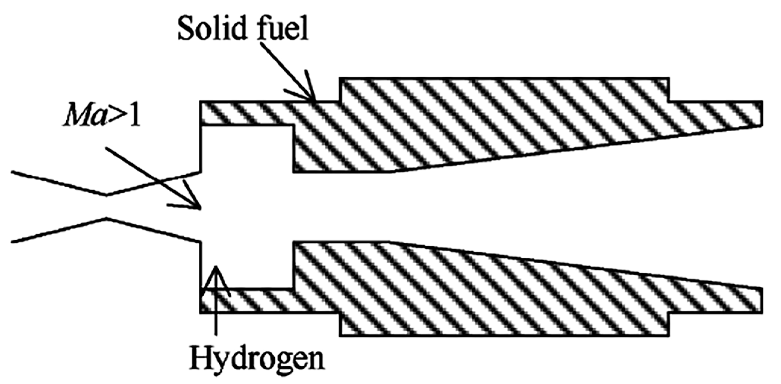
Research on solid-fuel scramjet technology first began at the Israel Institute of Technology and the United States Naval Postgraduate School. In 1989, Michael A. Witt [11] of the United States Naval Postgraduate School proposed the SFSJ configuration and carried out ground test research, as shown in Figure 2. The simulated height of the test is 24 km and the Mach number is 4.0. The results show that solid fuel can be burned in the supersonic combustion chamber, but the combustion needs to be maintained by hydrogen ignition in the combustion chamber cavity. However, the design had difficulties in ignition and flame stabilization, as well as low combustion efficiency.
Meanwhile, Michael A. Witt from the U.S. Naval Postgraduate School [11] also conducted experimental research on the DMSJ configuration for the first time, as shown in Figure 3. The experimental simulation flight conditions were an altitude of 24.4 km and a Mach number of 4.0, using HTPB as the solid fuel. The total mass flow rate of the incoming air was approximately 0.454 kg/s, divided into two equal mass flow paths. One path of air entered the subsonic combustion chamber, where it mixed with the solid fuel for combustion, producing a fuel-rich gas. The other path of air was injected into the supersonic combustion chamber from the wall at a Mach number of 2.4, where it further mixed and combusted with the fuel-rich gas produced in the subsonic combustion chamber. The results showed that the fuel-rich gas could undergo supersonic mixing combustion with the incoming bypass air in the combustion chamber, but the introduction of bypass air from the wall surface created high-intensity shock waves, leading to higher total pressure loss. Therefore, Witt recommended using a coaxial bypass intake method, which ensures the required mixing effect while effectively reducing the total pressure loss.
In 1990, C. Vaught [12] conducted a thermodynamic cycle analysis of the DMRJ under design conditions (24.4 km, Ma 6) based on Witt’s experiments. The analysis results indicated that when the combustion efficiency of the supersonic combustion chamber reached 70%, the performance of the dual-chamber configuration could be on par with that of traditional subsonic ramjet engines. In 1991, Angus [13] made improvements to the SFSJ configuration designed by Witt, dividing the combustion chamber into three sections: a concave chamber, a constant diameter section, and an expansion section, as shown in Figure 4. A small amount of hydrogen was still used for ignition in the concave chamber. The experimental results showed that combustion was mainly concentrated near the wall, with low fuel-to-mainstream mixing efficiency. The combustion chamber outlet could maintain supersonic flow, but the combustion efficiency of the solid fuel was only 57%.
In 1998, Ben-Yakar et al. [14] further improved the SFSJ configuration based on Angus’ design. The modified flame stabilization device featured a concave chamber with a certain aft edge inclination, as shown in Figure 5. The results indicated that this configuration could achieve ignition and stable combustion of solid fuel in supersonic airflow without the need for any external ignition devices. However, as the flame surface receded and the concave chamber disappeared, the flame stabilization recirculation zone gradually diminished, leading to engine shutdown.
In 1998, Abraham Cohen-Zur [15] of the Technion-Israel Institute of Technology conducted an experimental study on the effects of expansion angle and inlet parameters on the performance of the SFSJ combustor. The experimental results showed that the combustion efficiency of solid fuel decreases with the increase of combustion rate due to the high gas velocity in the supersonic combustion chamber and the poor mixing effect of solid fuel with incoming air.
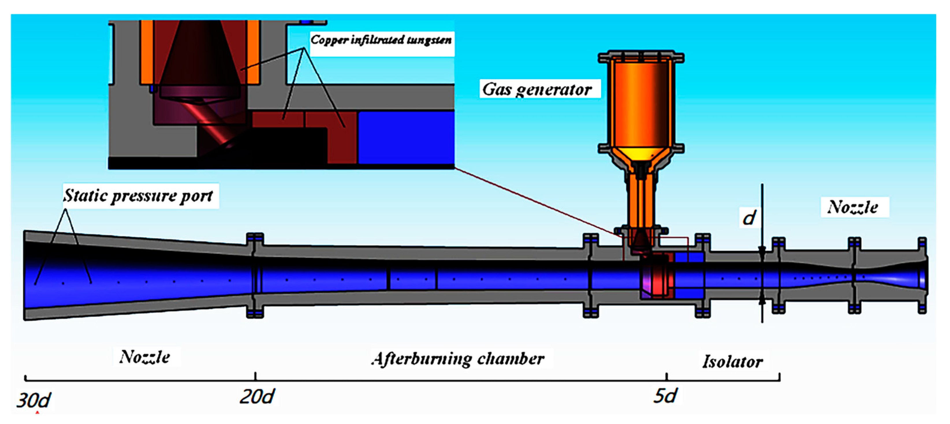
In 2016, Lv Zhong et al. [16,17] from the National University of Defense Technology proposed the SRSJ configuration, as shown in Figure 6, and conducted experimental research. This configuration uses a hydrocarbon-lean solid fuel as fuel, which sustains combustion within the gas generator. The primary fuel-rich gas generated from combustion is injected into the supersonic combustion chamber in the form of a high-enthalpy lateral jet, where it undergoes secondary mixing and combustion with the incoming airflow. The experimental flight conditions simulated an altitude of 17 km and a flight Mach number of 4. The results showed that the secondary fuel-rich gas at the gas generator outlet can self-ignite and combust in the supersonic airflow. The combustion efficiency and total pressure loss were 70% and 25%, respectively. This effectively addressed issues such as ignition difficulties, uncontrollable changes in the combustion chamber’s internal profile, and low mixing combustion efficiency in the solid-fuel scramjet.
Although no new configuration of the solid-fuel scramjet has been proposed in the past 10 years, the feasibility of the SRSJ has been verified by a large number of ground tests after more than 10 years of development since the SRSJ scheme was proposed. At the same time, because the SRSJ has the outstanding advantages of a simple structure, convenient storage, and a large specific thrust, and can solve the problems of poor flame stability, difficult gas flow regulation, and engine plane change, it is widely used as an aircraft power device with high space constraints and is the preferred power device for air-breathing hypersonic aircraft.

3. Supersonic Stable Combustion and Combustion Enhancement Technology

The achievements in liquid-fuel scramjet engine research have provided important references for the design of solid-fuel scramjet engines, as shown in Table 1. The studies on hybrid enhancement methods for liquid engines, such as active and passive mixing, have highlighted that using devices like cavities and aerodynamic ramps can effectively reduce total pressure loss and stabilize the flame, providing a theoretical basis for the hybrid technology of the solid-fuel scramjet.
The combustion time of fuel and air mixed in the solid-fuel scramjet is milliseconds, so how to organize fuel high efficient combustion in milliseconds becomes an important topic. After the fuel in the combustion chamber of a solid scramjet engine is ignited by a forced ignition method, an initial fire kernel forms near the ignition source, establishing a local combustion zone. Due to the high incoming flow speed, reliable flame stabilization measures are needed. It prevents the initial flame formed during the ignition phase from being blown out by the high-speed main stream after the external ignition source is turned off, thus ensuring continuous combustion in the solid-fuel scramjet combustion chamber.
Typically, flame stabilization technology focuses on two aspects: flame propagation mechanisms and energy feedback mechanisms. Flame propagation is influenced by the uniformity of fuel mixing, local equivalence ratio, turbulence intensity, and local pressure, temperature, and velocity. The formation of the energy feedback mechanism requires the generation of recirculation, which feeds high-temperature gases back into the ignition zone.
Currently, the SRSJ is widely used as a propulsion system for vehicles with high spatial constraints. Therefore, research on supersonic stable combustion and combustion enhancement technologies primarily focuses on the SRSJ. The combustion enhancement techniques commonly used in the SRSJ rely on lateral jets, aft steps, struts, and cavity devices. The specific advantages and disadvantages are summarized in Table 2. The cavity, as a flame stabilization device, has attracted attention from researchers worldwide [30,31]. It offers several prominent advantages, including a simple structure, low total pressure loss, and good combustion stability, while also effectively promoting fuel mixing. As a result, it is widely used in the design of SRSJ combustion chambers.
In 2012, Yu et al. [32] studied the mixed enhancement and flame stability characteristics of the cavity, and the results showed that a certain cavity inside the combustion chamber could improve the volume heat release of the combustion chamber, which could not only accelerate the fuel heat release, but also facilitate the total pressure recovery of the combustion chamber.
In 2012, Xinyan Pei et al. [33] conducted an analysis of the effects of the cavity/diameter (D/d) ratio and offset ratio (Dd/Du) on combustion chamber performance. For simplicity, the combustion chamber was divided into three sections: the cavity section, the cylindrical section, and the expansion section, as shown in Figure 7 and Figure 8. The recirculating flow within the cavity was found to provide stable flame stabilization, thereby improving the mixing rate and combustion efficiency. The detailed composition and key conditions of the cavity are shown in the figure. The study analysis revealed that combustion chambers without cavities were prone to shock-induced separation; compared to combustion chambers without cavities, the combustion efficiency of chambers with a well-designed cavity increased by 150%. As the cavity length increased, the total pressure loss decreased, which contradicted the conclusions drawn from liquid scramjet engines. When the cavity length-to-diameter ratio (L/D) was 4, the combustion efficiency was highest, with moderate total pressure loss.
In 2013, regarding the combined cavity flow field structure, Situ Ming et al. [34] conducted studies on several configurations of series-connected cavity arrangements. The results of both studies indicated that the combined cavity could enhance combustion performance. Wang Ningfei, Tao Huan, and others [35,36] investigated the impact of different cavity structural parameters on the combustion performance of the SRSJ. Their findings showed that the boundary layer separated from the leading edge of the cavity and reattached downstream, forming a free shear layer. The reactions within the cavity caused the gas to expand, leading to a slight increase in the boundary layer and the formation of a mixed supersonic and subsonic flow in the cavity region, which extended the residence time. Therefore, an appropriate cavity could promote mixing and improve combustion efficiency, with an optimal cavity length-to-depth ratio that yielded the best combustion chamber performance.
Fan Zhouqin et al. [37] conducted experimental and numerical studies on the combustion flow field inside a scramjet combustor equipped with cavities. The results showed that both series-connected and parallel-connected cavities could enhance mixing and combustion. The series-connected cavities improved mixing and combustion efficiency, while the parallel-connected cavities accelerated the combustion heat release.
In 2018, Liu Yang et al. from Northwestern Polytechnical University [38,39] carried out experimental and numerical research using center-mounted splitter plate gas injection combined with cavity and oblique splitter configurations for flame stabilization with the engine structure. The experimental results indicated that the engine had a combustion efficiency of 49% and a specific impulse of 367 s. Additionally, they completed an integrated duct design for this engine configuration.
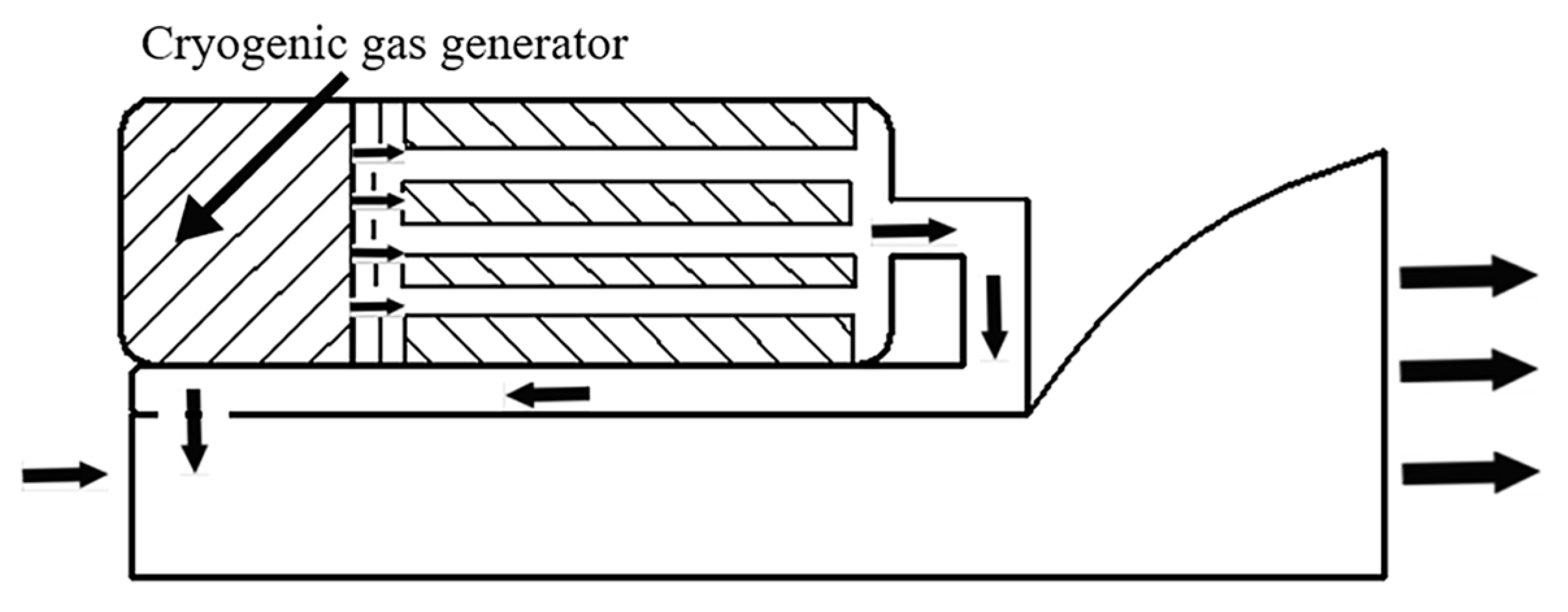
In 2018, Salgansky et al. from the Russian Academy of Sciences [40,41] conducted computational analysis on the performance impact of using a low-temperature gas generator for the SSRJ. The configuration is shown in Figure 9. The analysis assumed that the low-temperature, fuel-rich gas exiting the gas generator could effectively cool the walls through convective heat transfer. This provided a new approach to addressing the thermal protection issues associated with prolonged operation of a solid scramjet.
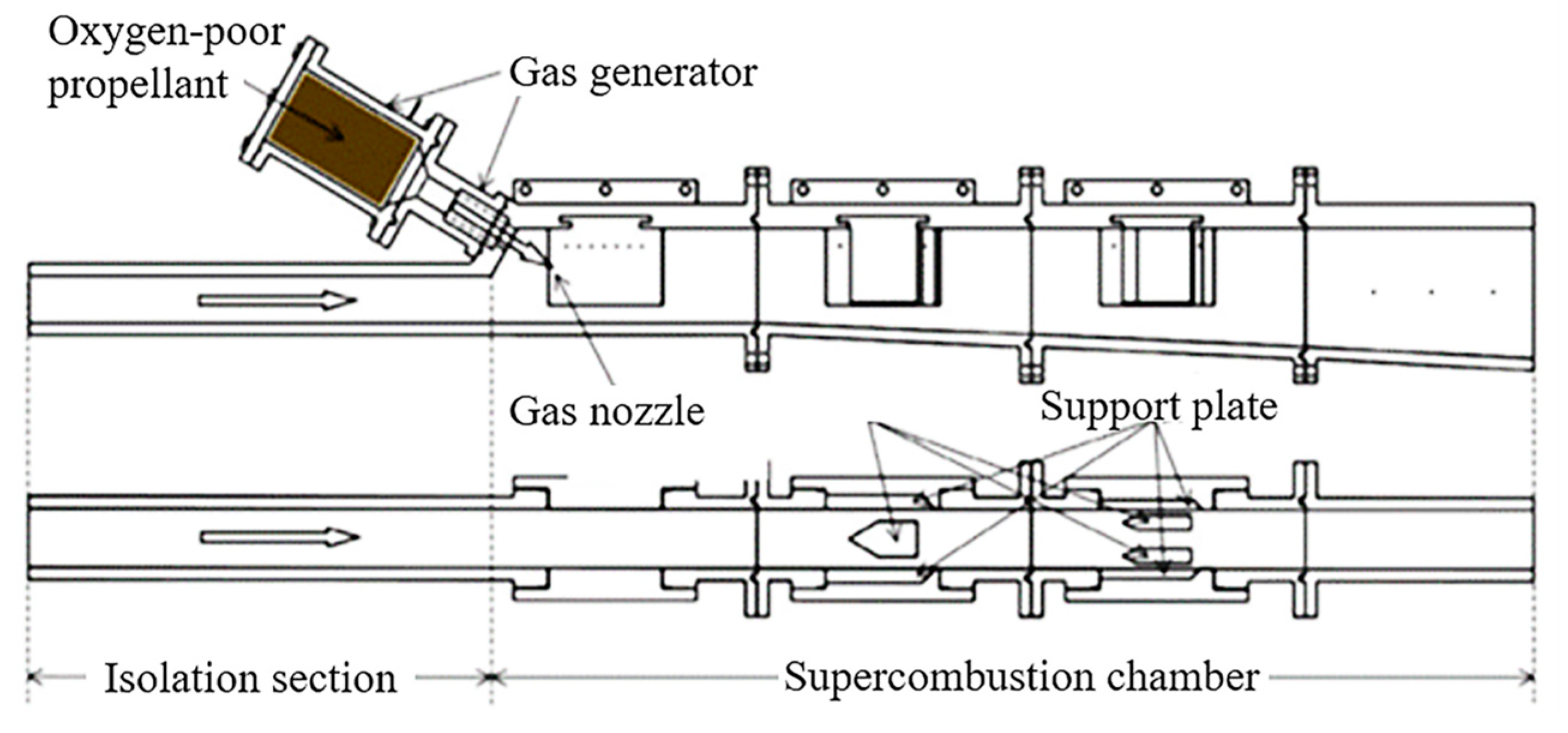
In 2019, Li Chaolong et al. from the National University of Defense Technology [42,43,44] conducted experimental and numerical studies using oblique splitters, cavities, splitter plates, and their combinations, with the engine configuration shown in Figure 10. The results indicated that the flow disturbance devices played a significant role in the ignition and combustion stability of fuel-rich gases. The engine with a combination of a cavity and a splitter plate had a combustion efficiency of approximately 0.7, but a relatively low total pressure recovery of about 0.25. The overall combustion efficiency mainly depended on the combustion of solid particles, and the cavity and splitter plate combination required aerodynamic configuration optimization.
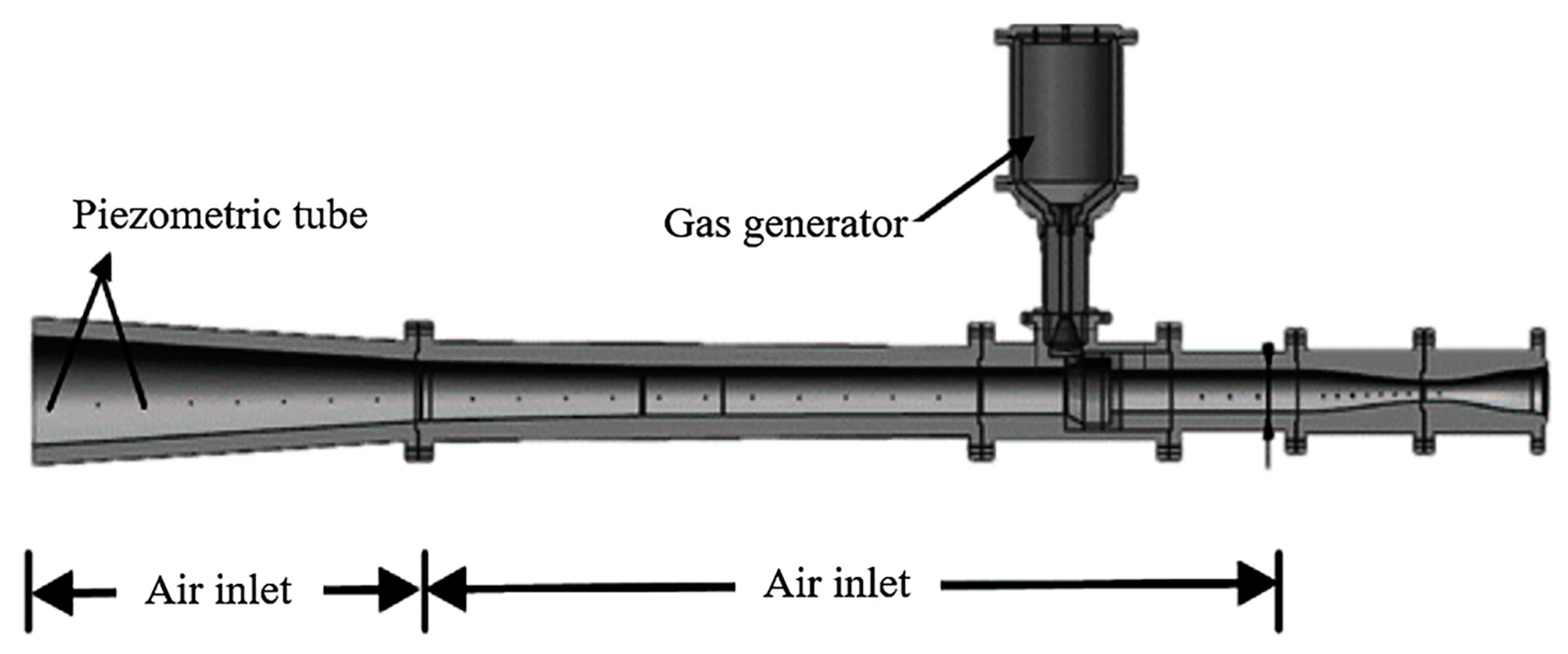
Liu Jie et al. from the 31st Institute of the Third Academy of China Aerospace Corporation [45] proposed a combined configuration of a cavity and wall injection for solid-fuel scramjets. The experimental configuration is shown in Figure 11. The results indicated that the impact of the gas injection method on engine performance was significantly greater than the effects of the cavity length-to-depth ratio and cavity depth. Increasing the low-speed region near the cavity and enhancing particle recirculation could optimize combustion performance.
In 2019, Liu J [45] proposed a SRSJ engine combining a cavity and an aerodynamic ramp, using a boron-based propellant with a mass fraction of 10%, as shown in Figure 12. Through full-scale ground experiments and numerical simulations, it was concluded that for the SRSJ engine, the combination of the cavity and aerodynamic ramp created a larger low-speed region near the cavity, enhanced particle recirculation, and optimized combustion performance.
In 2019, Li C [42] et al. proposed a novel cavity-supported composite solid rocket scramjet engine configuration, using carbon particles to experimentally and numerically analyze the combustion characteristics relative to the combustion chamber. The results showed that the recirculation zone formed by the cavity and the supports promoted ignition and stabilized the flame, improving the combustion efficiency of the scramjet engine. However, the total pressure recovery rate was relatively low. S. Aravind [46] et al. designed a parallel pillar injection air intake system for a scramjet engine combustion chamber operating in a Mach 2 environment. The results indicated that after modifying the geometry of the injector, the interaction between shock waves and shear layers within the combustion chamber increased the local turbulence intensity, generating additional vortices that enhanced the mixing and combustion performance of the chamber.
In 2020, Nozomu Kato [47] experimentally investigated the flame behavior of cavity-type and non-cavity-type flame holders under scramjet mode, ramjet mode, and non-starting conditions. When the flow was not obstructed (i.e., scramjet mode), the cavity enhanced combustion and stability by increasing the partially premixed region of the flame. However, the presence of the cavity promoted downstream thermal blockage. The cavity behaved similarly to an acoustic source, altering the main frequency of flame oscillations, and higher resonance frequencies were observed in the model with a cavity. The study found that the flame behavior in both the cavity and non-cavity models was similar; however, the model with the cavity required less time due to enhanced combustion.
In the same year, Nakaya et al. [48] reported another form of oscillation with a frequency of approximately 120 Hz. Using a post-processing method similar to their CH* chemiluminescence imaging (sparse-promoted DMD), they observed that the flame within the entire cavity was oscillating. It was concluded that fluctuations in the fuel jet were the source of this instability, and it only occurred at equivalence ratios where the flame was stabilized within the cavity.
In 2021, Lakka Suneetha [49] conducted a numerical simulation study to investigate the effect of cavity geometry based on support plates on the performance of the combustion chamber of a scramjet engine. The results indicated that the combustion chamber with a cavity structure formed a strong recirculation zone in the cavity region, which effectively improved fuel mixing and combustion efficiency. The size of the recirculation zone depended on the distance between the support plate and the cavity, as well as the length of the cavity. Additionally, a shear layer existed in the cavity region, and weak shock waves were generated at the cavity’s trailing edge, which degraded the performance of the scramjet engine’s combustion chamber. It was suggested that an appropriate rearward inclination angle of the cavity should be considered in subsequent designs.
In the same year, J.J. van der Lee et al. [50] experimentally studied the combustion instability induced by the transition of combustion modes in a supersonic ramjet engine with a stable cavity. This study was conducted in a combustion chamber model of a supersonic ramjet engine using ethylene as the fuel, with an inlet Mach number of 2.2, stagnation pressure of 12.1 atm, and stagnation temperature of 1270 K. Two fuel injectors were used, one upstream of the cavity and the other within the cavity. Throughout the study, the overall equivalence ratio was constrained to 0.3, and the fuel flow distribution between the two injection locations was varied. When fuel was injected only upstream of the cavity, combustion primarily occurred within the cavity, with weak flames downstream along the wall boundary layer. By transferring 10–15% of the fuel to the injector at the bottom of the cavity, the combustion intensity along the downstream wall gradually increased. As the fuel ratio injected into the cavity was further increased to 29%, the flames spread into the main flow path downstream of the cavity, exhibiting a strong combustion mode, indicating improved mixing and combustion efficiency, with a sharp rise in pressure, suggesting the formation of a shock wave train in the combustion chamber’s expansion section. However, when 21% of the fuel was transferred to the injector in the cavity, unstable combustion occurred, with intermittent transitions between the weak and strong combustion modes. The unstable transition between the two combustion modes could be considered as low-frequency combustion instability.
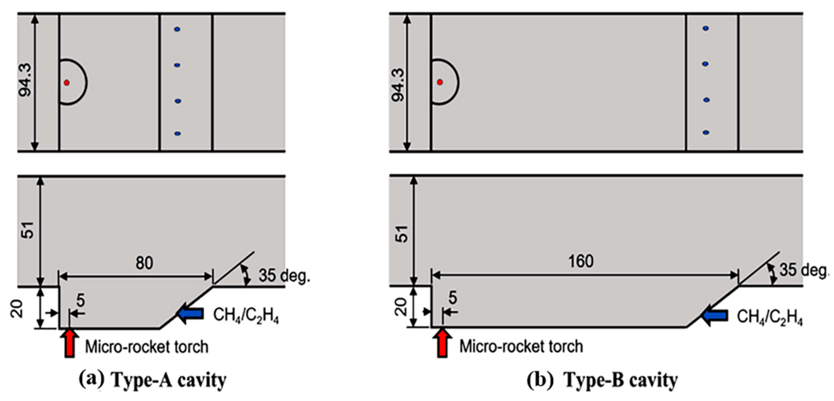
In 2023, Shinichiro Ogawa [51] studied the forced ignition process in cavity flame stabilizers. The detailed diagram of the supersonic ramjet engine combustion chamber flow path and cavity is shown in Figure 13. According to the OH * intensity, in both types of cavities, as the fuel flow increased, the flames extended into the cavity slopes. At low fuel flow rates, stable combustion flow could be achieved in the shear layer and within the cavity. Furthermore, when the methane-ethylene mixed fuel, after direct entry of the torch gas into the air-rich shear layer, reached the cavity’s leading edge, the mixed fuel was ignited in the shear layer. The influence of fuel flow on the cavity flow field was also studied. In the type A cavity, there was no significant difference in the amplitude of dynamic mode decomposition (DMD) modes because the fuel flow rates differed only slightly. Low-frequency oscillations below 1000 Hz were formed by the flame feedback from the fuel and the mini-rocket torch injectors, as well as flow fluctuations around the cavity. Additionally, high-frequency oscillations above 1000 Hz were generated by the turbulent boundary layer entering the cavity.
Rajesh Kumar [52] studied the effect of fuel flow rate on the pressure rise in the combustion chamber and the shock wave train in the isolator section. The study altered the fuel flow rate of gaseous hydrogen laterally injected through a sonic hole upstream of the cavity by changing the pressure at the fuel inlet, while keeping the flow parameters at the air inlet with a Mach number of 2.01 constant. As shown in Figure 14, the three different flow rates corresponded to three distinct pressure ratios. The regions of sonic and subsonic Mach numbers are color-coded. At low to moderate fuel flow rates, shock wave structures were also observed in both the cold and reactive flow fields. It was found that the shock wave structures were primarily influenced by the momentum ratio of the jet in the transverse flow, the dynamics of the leading and trailing edges of the cavity, and the shear layers formed within the cavity.
In 2024, Jianheng Ji et al. [53] conducted an experimental study on the flame behavior in the combustion chamber of a cavity-based scramjet operating at a Mach number of 2.92 supersonic flow. Different equivalent ratios were tested for each cavity geometry, as shown in Table 3. Figure 15 shows the time-average flame luminosity for various scenarios, all of which were obtained under stable combustion conditions. It can be observed that the flame of H9ER0.34 and H12ER0.35 is mainly concentrated in the shear layer and near the wall area of the downstream cavity. It is worth noting that in both cases, the angle of the high-brightness flame boundary is relatively small, and the front of the high-brightness flame region is mainly located in front of the center of the cavity. The region with stronger time-average flame luminosity is mainly located above the back wall of the cavity.
The test results showed that the increase in equivalent ratio leads to the transition from the lift shear layer mode to the ramjet mode. As long as flame stabilization is achieved, raising the height of the back wall of the cavity can improve the combustion chamber’s spontaneous combustion capability and facilitate the transition from the lift shear layer mode to the ramjet mode. It was found that increasing the equivalent ratio and the height of the back wall also led to stronger combustion oscillations; In addition, raising the height of the back wall of the cavity can enhance the main frequency of low-frequency oscillation in the combustion chamber. Finally, it was proved that the application of spark plasma can effectively suppress these low-frequency combustion oscillations, which is a promising active control method for scramjet engines.
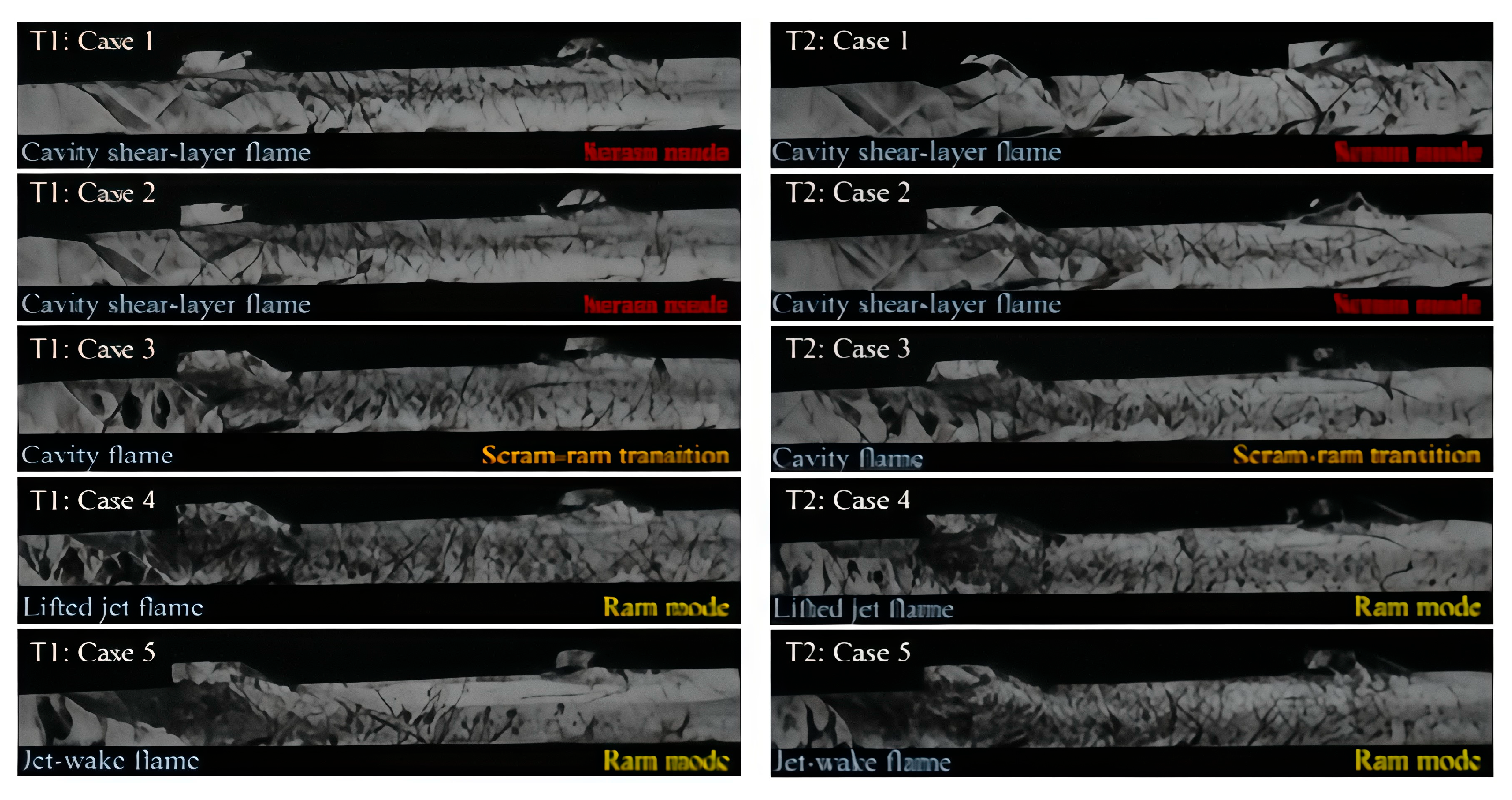
Through their test cases, Min-Su Kim et al. [54] found that an emergency shutdown mode in the form of a cavity shear layer flame was formed, with a maximum equivalent ratio of 0.17. When the equivalent ratio is low, only weak oblique shock waves are formed along the combustion flow field. However, as the equivalent ratio increases, a slanted preignition shock wave is formed and fixed at the leading edge of the cavity. This means that the heat and pressure released by combustion increases, and the pressure gradient between the combustion chamber and upstream gradually increases. Through the results of T1 ignition and T2 ignition with an equivalent ratio of 0.1, it was found that when the fuel injection pressure and the resulting jet on the momentum of free flow are low, the influence of holes and shear layer is dominant, forming a cavity shear layer flame, and no emergency shutdown mode in the subsonic zone continues, as shown in Figure 16. When the equivalent ratio is 0.3, the shock train begins to develop with the transverse expansion of the combustion flow field, and the local subsonic zone is confirmed.
Emil Alunno et al. [55] studied and explored flame stability in the combustion chamber of a scramjet. It was found that when the equivalent ratio is between 0.97 and 1.22, the flame can be stabilized after ignition. For equivalent ratios below 0.97, the lower fuel supply causes lean oil to stall, where the flame does not stabilize after consuming the initial dose of ethylene. When the equivalent ratio is greater than 1.22, the lack of oxidant in the mixture prevents the flame from stabilizing because too much fuel is supplied.
In summary, the cavity has been recognized as a flame stabilizer consisting of a forward-facing step and a backward-facing step. Compared to the backward-facing step, the recirculation zone formed by the airflow passing through the cavity is larger, with a higher static temperature, providing stronger flame stabilization capabilities. Additionally, the shock waves generated by the shear layers reattaching are relatively weaker, resulting in smaller total pressure losses. The cavity generates a recirculation zone within the mainstream supersonic flow, which increases the overall flow residence time and creates favorable conditions for flame stabilization. The cavity flame stabilizer has been regarded as the most promising and feasible flame stabilizer for scramjet combustion chambers, with advantages such as a simple structure, strong flame stability, low drag, and minimal total pressure loss. As a result, it has attracted significant attention from researchers worldwide. Over the years, both numerical and experimental studies have demonstrated the effectiveness of the cavity, and various methods have been explored. Research has been conducted not only to examine the effects of shape and size changes (such as depth, length, and ramp angles) but also to investigate the impact of quantity. Additionally, within the supersonic flow field, the cavity has been shown to promote fuel-air mixing by inducing periodic oscillations.

4. Engine Thermal Protection Technology

The scramjet engine operates at high flight Mach numbers, subjecting its external surface to severe aerodynamic heating. To maintain a stable external structure and ensure normal flight, thermal protection is essential for its exterior. Under the combined effects of high-enthalpy incoming flow and heat release from combustion, the interior of the scramjet engine also experiences intense thermal loads. The internal flow field of the scramjet engine is complex, and the combustion chamber is the primary location for mixing and combustion; therefore, thermal protection for the combustion chamber is particularly critical. Consequently, thermal protection technology is a crucial topic in the research of scramjet engines.
According to the classification of Kelly et al. [56], thermal protection technology can be divided into the following three ways:
(1) Passive thermal protection: This method does not rely on an external coolant to take away heat, usually through the use of high-heat-resistant materials, thermal shielding, and other means to naturally prevent heat conduction and radiation.
(2) Active thermal protection: This method relies on external devices to provide the coolant and requires a power system to circulate the coolant to ensure that the temperature is controlled within a safe range.
(3) Combined active and passive thermal protection: Although this method uses coolant to transfer heat, no additional device is required to supply or circulate coolant. The role of the coolant is usually achieved through the design of the structure itself, reducing the transfer of heat.
Because the heat flux of different parts of the engine and the allowable temperature of the structural material are different, the thermal protection methods for different parts are also different and need to be selected and designed according to the specific working environment and heat load.

4.1. Passive Thermal Protection

Currently, common high-temperature-resistant materials are mainly classified into refractory high-temperature alloys, high-temperature-resistant composites, and high-temperature-resistant ceramics. Due to the high density, difficult processing, and susceptibility to oxidation at high temperatures, refractory alloys have several disadvantages as passive thermal protection materials for scramjet engines. In contrast, composite materials and high-temperature-resistant ceramics offer more promising applications in passive thermal protection. Because C/C composites have the advantages of low density and high strength, they are particularly suitable as structural materials for air-breathing vehicles. However, C/C composites have poor oxidation resistance and are prone to oxidation at high temperatures [57], which limits their application in high-heat-flux regions of scramjet engines, such as the nose cone and leading edges. To address the oxidation and ablation issues of C/C composites, several studies have proposed solutions from the perspectives of coatings and matrix modifications [58,59] to meet their requirements in scramjet engines. For example, the temperature limit of C/SiC composites has been increased to above 1800 K [58], which can meet most of the passive thermal protection needs. In the U.S. Air Force’s HyTech program, C/SiC composites with CVD-SiC coatings endured thermal testing for 600 s at Mach number Ma = 8 [59].
For the leading-edge, inlet and support-plate components made of C/SiC composite materials, thermal tests have also shown that they can meet the thermal protection requirements under specific working conditions [60,61]. In view of the shortcomings of composite material limits, the temperature not being high enough, and easy oxidation, some studies began to consider ultra-high-temperature ceramics as hypersonic vehicle thermal protection materials. The melting point of ultra-high-temperature ceramics can reach more than 3000 °C [62], which has broad application prospects in the passive thermal protection of scramjet engines. However, since ultra-high-temperature ceramics are generally boron, nitrogen, and carbon compounds of transition metals, which are easy to oxidize at high temperatures, ZrO 2 or SiC are usually added in use to enhance their oxidation resistance [63].
Due to its low thermal conductivity, high-temperature insulation material can effectively block the heat flow to the interior and greatly reduce the surface heat flux. NASA’s X-43A and X-51A hypersonic vehicle fuselage surfaces were protected by heat-resistant ceramic insulation materials and achieved the expected effect [3,64]. With the increase in flight distance and flight Mach number, the thermal load of materials and structures will increase sharply, and active cooling must be adopted to protect the engine.

4.2. Active Thermal Protection

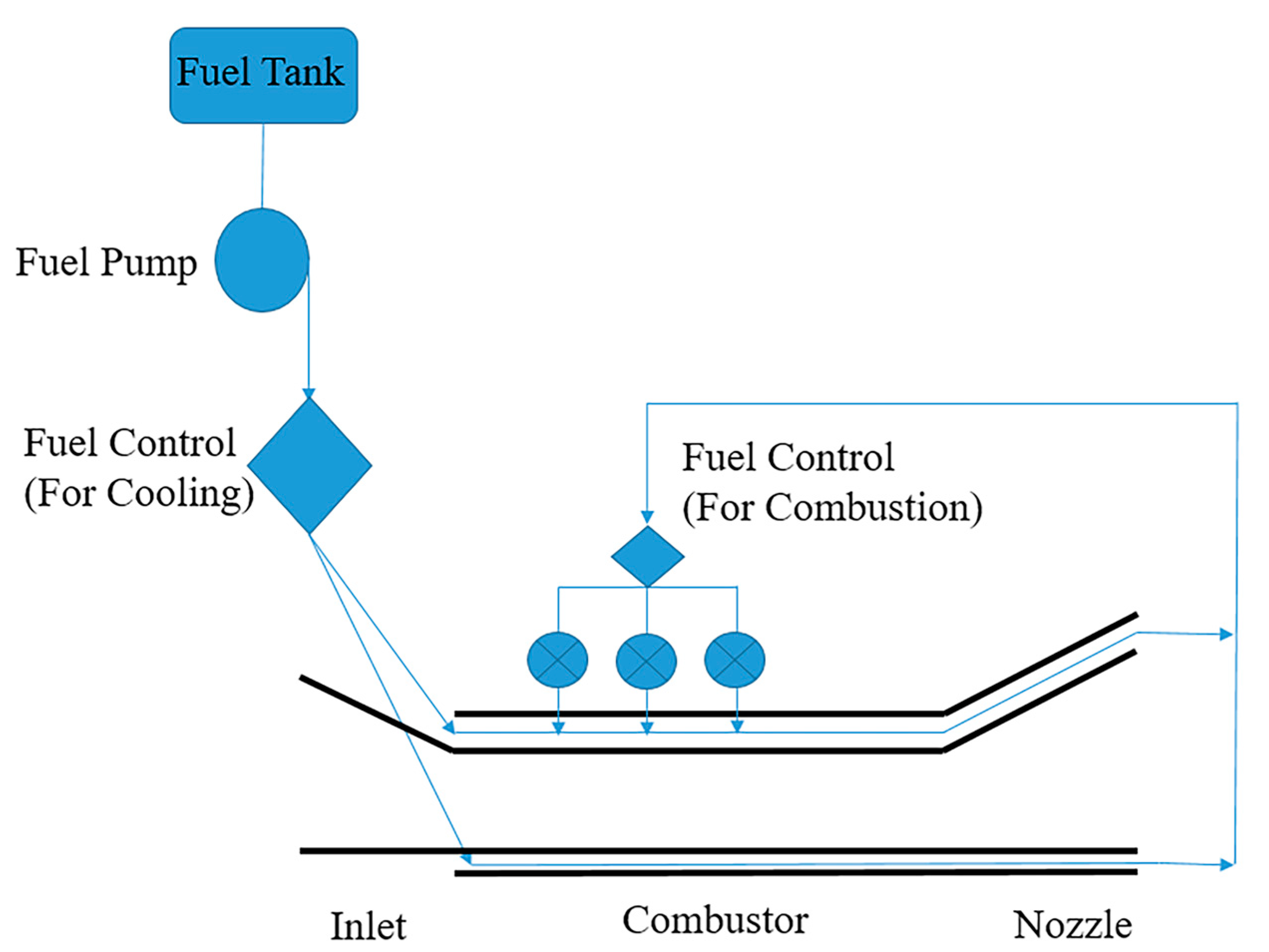
Active thermal protection mainly includes regenerative cooling, film cooling and sweat cooling [65]. In regenerative cooling, the coolant flows through the cooling channels, and removes heat through the convection tropics [66]. Film cooling works by introducing coolant to form a wall adhesion film, reduce heat exchange of the high-temperature gas and wall surface, and can play a good role in protecting parts with high heat flux and temperature [67]. During sweat cooling, the coolant penetrates into the wall surface through the porous medium material to form a continuous wall adhesion film [68]. Sweating cooling can also be regarded as a limiting form of membrane cooling. Compared with other thermal protection methods, regenerative cooling has high fuel and heat utilization efficiency and almost no performance loss, which is the first choice for scramjet thermal protection at present. The schematic diagram of regenerative active cooling of scramjet engine is shown in Figure 17 [69]. Because fuel is used as the coolant in regenerative cooling, the choice of fuel is also a key factor affecting regenerative cooling.
At present, most of the various types of aeroengines use hydrogen or hydrocarbon fuel as fuel [70]. Compared with hydrocarbon fuel, although the specific impulse of hydrogen is higher, the cooling capacity and combustion heat of hydrogen per unit mass are also higher, but the flammable range of hydrogen is very wide, and it is a gas at normal temperature and pressure, and transportation and storage are very inconvenient. In addition, due to the small molecular weight of hydrogen, even when using high-pressure storage devices, the density is still very low, and the use of hydrogen as a fuel will greatly increase the volume and mass of the structure. Hydrocarbon fuels have the following advantages over using hydrogen as a fuel. First of all, hydrocarbon fuel has a higher density, and the use of hydrocarbon fuel can significantly reduce the volume of the fuel tank and reduce the structural weight [71]. Secondly, hydrocarbon fuels are stable at room temperature, safer, and cheaper to store and transport. In addition, at high temperatures, the hydrocarbon fuel will crack, generating small molecules that are easy to ignite and burn, and the pyrolysis reaction of the hydrocarbon fuel is generally endothermic, which can increase the heat absorption capacity of the coolant.
Wenerberg et al. [72] investigated the heat transfer enhancement effect of large aspect ratio cooling channels using experimental and simulation methods, with supercritical pressure nitrogen as the working fluid. The results indicated that, under the same pressure drop, large aspect ratio cooling channels could reduce the wall temperature, while under the same wall temperature conditions, they could decrease the pressure drop. Chen et al. [73] performed numerical simulations of the flow and heat transfer characteristics of supercritical pressure hydrocarbon fuels in cooling panels. The study showed that by reducing the inlet cross-sectional area of the cooling channels, i.e., using a throttling method at the channel inlet, the flow distribution in the channels could become more uniform, which significantly reduced the maximum wall temperature and resulted in a more uniform temperature distribution on the panel.
Hydrocarbon fuels generally have complex compositions and cannot be considered simple pure substances. Deng et al. [74] measured the critical pressure and temperature of domestic aviation kerosene RP-3 using experimental methods. Based on the critical opalescence phenomenon, they determined that the critical pressure and temperature of RP-3 were 2.33 MPa and 645.04 K, respectively. Wang et al. [75] also obtained the critical pressure and temperature of RP-3 from the critical opalescence phenomenon, which were found to be 2.3 MPa and 646 K, closely matching the results from Deng et al. Additionally, Deng et al. [76] experimentally measured the variations in density, specific heat, and viscosity of domestic aviation kerosene RP-3 with temperature.
In addition, some studies have suggested that the deterioration of heat transfer of supercritical pressure hydrocarbon fuels may be caused by the drastic change of physical properties near the pseudo-critical temperature [77]. There is another noteworthy phenomenon in the heat transfer process of supercritical pressure fluids; that is, oscillation of flow and pressure will occur under specific working conditions [78]. Some studies have pointed out that the oscillation of flow and pressure may cause damage to the structure and reduce the service life of the structure [79]. However, some studies have also shown that such unstable characteristics of flow and pressure can enhance heat transfer and reduce wall temperature, which may bring certain benefits to thermal protection [80]. In view of the phenomenon of unstable heat transfer of supercritical pressure fluid and its possible influence, some scholars have carried out more detailed research. Due to the limitations of observation methods, most studies on the instability of heat transfer in supercritical pressure fluids are still at the stage of mechanism exploration [81,82].
A study on the instability of heat transfer of carbon dioxide under supercritical pressure showed [83] that the drastic change of physical properties near the pseudo-critical temperature is likely to cause the instability of flow and heat transfer. Wang et al. [84] conducted an experimental study on thermoacoustic instability in the flow and heat transfer of supercritical pressure kerosene and proposed that the generation process of thermoacoustic instability could be divided into four stages: thermal stability, thermal instability, initial thermoacoustic instability, and highly developed thermoacoustic instability. Hydrocarbon fuels crack at high temperatures. Studies have shown that a pyrolysis endothermic reaction can greatly increase the total heat sink of fuel [85] and reduce the amount of coolant used. In addition, the pyrolysis of hydrocarbon fuels produces small molecular products that are easy to ignite. However, a serious problem caused by the cracking of hydrocarbon fuels is carbon coking [86,87]. When the temperature or cracking rate is high, a carbon layer is formed on the inner wall of the cooling channel. Wall area carbon is similar to a layer of insulation material, which will greatly reduce the heat transfer coefficient of the coolant and the inner wall of the channel, block the heat transfer, and cause the wall temperature to be too high. Severe carbon coking can even block the entire cooling channel, resulting in the failure of the coolant and fuel supply system. How to avoid carbon coking is a problem that must be solved in regenerative cooling. How to use the cracking reaction to improve the cooling capacity of hydrocarbon fuel without bringing new problems is also a hot topic in current research.
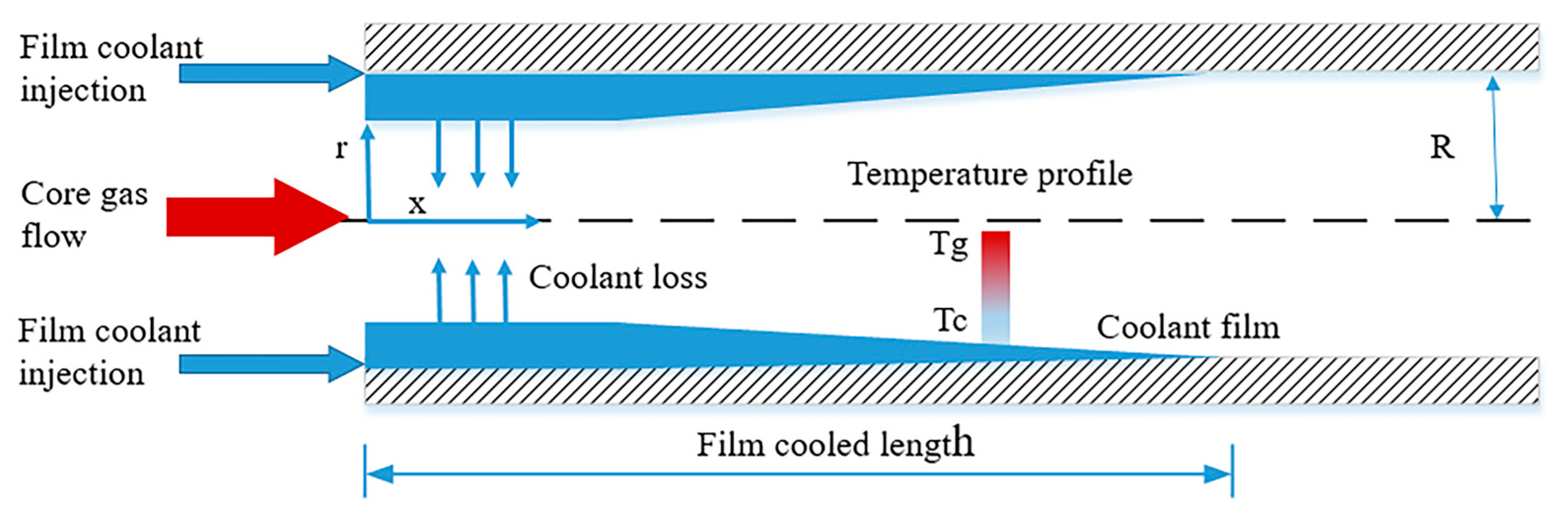
Film cooling effectively reduces the temperature and heat flux density of the gas-side wall by introducing a thin film of coolant between the high-temperature gas and the wall, as shown in Figure 18 [88]. In a typical film cooling configuration, cooling gas is introduced through holes or slots on the wall. Compared to the hole configuration, using slots can form a more uniform coolant film. Since its application in thermal protection for aerospace engines, film cooling has been widely used in the thermal protection of high-temperature components in gas turbines [89] and rocket engines [90]. Due to its simple structure and high cooling efficiency [91], it is well suited for thermal protection of high-temperature components in hypersonic ramjet engines [92]. Many researchers have conducted experimental or simulation studies on the mechanisms and applications of film cooling [93,94], and these studies indicate that the influencing factors of film cooling are numerous and the patterns are complex. Schuchkin et al. [95] employed numerical simulation to study the effect of tangential film cooling in supersonic flows. The study found that numerical simulations can predict the overall characteristics of the flow and pressure fields, including the interaction between the mainstream and the film, but there are still significant discrepancies between the simulated and experimental results for the wall pressure and temperature distribution.
With the development of materials science and hypersonic vehicles, more and more research has been done on sweat cooling and its application [96]. The thermal protection principle of sweat cooling is shown in Figure 19 [97]. The coolant flows through the porous medium and forms a continuous film on the high-temperature gas side to protect the wall surface, so it is also regarded as a limiting form of film cooling. Sweat cooling not only forms a film on the surface to block the heat, but also absorbs heat when the coolant vaporizes, so the heat flux between the gas and the wall can be greatly reduced, which has obvious advantages compared to other thermal protection schemes.
Some studies have studied sweat cooling from the aspects of flow and heat transfer between the main stream and sweat cooling [98,99]. Jiang et al. conducted a large number of studies on sweating cooling [100,101,102] and found that increasing the coolant injection rate can effectively reduce the wall temperature and heat transfer coefficient. When the injection rate is 1%, the wall heat transfer coefficient can be reduced by about 50%. The study on the effect of the shock wave in sweating cooling shows that the increase of air temperature and pressure after a shock wave will reduce the injection rate of coolant, which will lead to a decrease in sweating cooling efficiency and an increase in wall temperature. In addition, they also carried out research on the combination of air film cooling and sweat cooling thermal protection methods and found that this thermal protection method can effectively protect the leading edge and other parts of the support plate.

4.3. Combined Active and Passive Thermal Protection

Considering the complexity of the structure and the difficulty of processing, the thermal protection of different parts of the scramjet engine usually adopts passive cooling or active cooling separately. However, with an increase in the flight Mach number, the thermal load of the engine will increase sharply. When the thermal load is very large, passive cooling or active cooling alone may not be able to achieve the protection of the structure and materials, and at this time, it is necessary to use a combination of active and passive cooling thermal protection schemes to protect the specific structure and parts of the engine. A typical thermal protection scheme combining active and passive cooling [103] uses a layer of passive thermal protection material on the side near the gas to protect the active cooling structure.
Using C/SiC ceramic matrix composites as the gas-side material and implementing regenerative cooling for high heat flux areas can effectively address the challenge of limited coolant flow, meeting the long-term thermal protection requirements of the engine. Paquette et al. [104] introduced a regenerative cooling panel made of high-temperature-resistant C/SiC composites on the gas side at high temperatures. In their study, they also analyzed the thermal conductivity and thermal stress of the structure, finding that selecting an appropriate matrix material can improve heat transfer between the composite material and the regenerative cooling panel.
Bouquet et al. [105] developed a cooling panel entirely made of C/SiC composites and conducted thermal validation experiments on the structure. The results showed that the cooling panel made entirely of C/SiC composites could withstand multiple tests under a heat flux of up to 1.5 MW/m2, with the structure remaining intact and without leakage. However, due to material and structural factors, the current passive and active thermal protection technologies still face the following issues. First, the difference in thermal expansion coefficients between passive and active thermal protection materials leads to thermal stress and strength issues. Second, for regenerative cooling panels made entirely of composite materials, due to their porous nature, there is a risk of coolant leakage under high pressure. Moreover, the effective bonding between composite materials and metals, along with low thermal efficiency, are also key factors limiting their application.

5. Improvement of Solid-Fuel and Combustion Performance

The SRSJ uses oxygen-poor propellant, and the lower oxidant content relatively reduces the amount of fuel carried, and thus shortens the working time of the engine. In order to improve the specific impulse of solid rocket scramjet engines, researchers are working to reduce the oxidizer content while ensuring the fuel’s self-sustaining combustion ability, so as to maximize the injection efficiency. With the decrease of oxidizer content, the spontaneous combustion performance of the fuel decreases, and the combustion efficiency decreases significantly. The research on oxygen-poor solid fuel mainly focuses on how to maintain high combustion efficiency while reducing oxidant content. To this end, researchers often increase the energy density of the fuel by adding fuel additives such as metal fuel or boron powder, which can significantly increase the heat of the fuel. The ignition performance and combustion mechanism of these propellants have been extensively studied by scholars at home and abroad, which provides an important reference for the optimization and improvement of propellants.
Compared with the liquid-fuel scramjet, the solid-fuel scramjet has the advantages of high propellant density and low manufacturing and maintenance costs, so it has been paid more and more attention by scholars at home and abroad, as shown in Table 4. These advantages promote the research progress of the solid-fuel scramjet.
In order to increase the energy density of propellants, high-energy metals, such as magnesium, aluminum, and boron are generally added to oxygen-poor solid-fuels. The rich combustion gas produced by propellant combustion in the gas generator contains a large number of solid particles, which enter the supersonic combustion chamber and further burn with the incoming air to release energy. Thermodynamic calculation shows that the energy contained in solid particles accounts for about 70% of the total energy of solid fuel, so the combustion efficiency of solid particles in the supersonic combustion chamber greatly determines the performance of the solid rocket scramjet.
Rosenband [106] divided the cracking of oxide film on the surface of metal particles into three processes: First, the metal particles expand under heat, which makes the oxide film on the surface stressed; when the stress reaches the limit of the oxide film, the fracture begins from a certain point on the metal surface; the metal particles continue to absorb heat, so that the oxide film on the surface of the metal is broken in many places, when there is sufficient oxidizing agent in the environment, to achieve the conditions of violent reaction, that is, the combustion process.
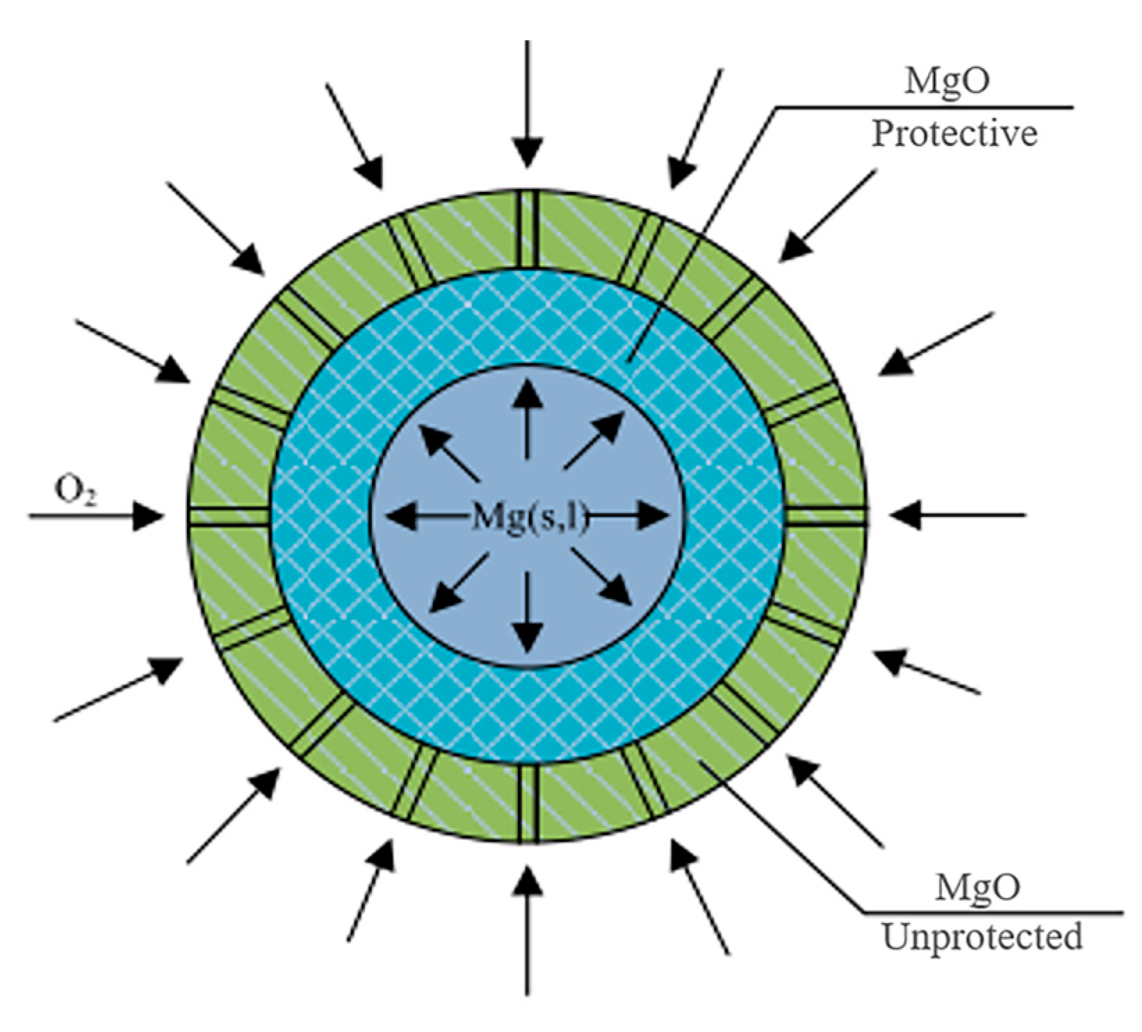
H. Cassel and Liebman [107] learned from the droplet evaporation model of hydrocarbon fuel, assumed that the combustion process of magnesium particles was controlled by the diffusion of O2 and that the Mg-O2 chemical reaction was completed instantaneously, and established a quasi-steady-state combustion rate model. Brzustowski and Glassman I [108] established the diffusion flame model by studying the combustion process of magnesium particles in O2. The parameters of the particle consumption rate, particle surface temperature, flame surface temperature, and location can be calculated according to the model. In order to more accurately describe various phenomena in the particle ignition process, Rosenband et al. [109] established a theoretical model for the ignition of a single magnesium particle, as shown in Figure 20. In the model, the oxide layer on the surface of the particle was divided into an internal protective oxide layer and an external non-protective oxide layer.
The model is based on estimation of the stress at the metal–oxide interface and can quantitatively describe the complex ignition process of metal particles in an oxidizing gas atmosphere. Due to the high boiling point temperature of aluminum, scholars have carried out a lot of research on the types of chemical reactions in the combustion of aluminum particles, the homophase reaction, or the heterophase reaction. In order to determine the type of chemical reaction during the combustion of aluminum particles, Badiola [110] monitored the change course of AlO spectral intensity while measuring the combustion temperature of the particles. The experimental study showed that the ignition combustion process of aluminum particles can be divided into the gas phase flame building stage, the stable gas phase combustion stage, and the extinction stage. Oxygen content has a great influence on the combustion characteristics of aluminum particles. When oxygen content is less than 15%, the combustion of aluminum particles is mainly a surface chemical reaction, but there is still an inevitable gas phase combustion chemical reaction. In addition, Mohan [111] presented experimental results of the ignition of micron-sized spherical Al particles by a CO2 laser in H2O/N2,CO2, air, H2O/air, and CO2/O2 gaseous environments. Al powder with nominal particle sizes in the range of 4.5–7 lm was aerosolized using a parallel plate capacitor by charging particles contacting the electrodes. In experiments, for a given environment and selected particle velocity, the laser power was increased until the particles ignited. The laser power thresholds required for ignition of spherical aluminum particles were measured at varied particle velocities for each environment. The lowest thresholds were found for the CO2/O2 mixture and the highest for the H2O/N2 mixture. Addition of O2 to H2O or CO2 reduced the ignition thresholds. The experimental data were processed to determine the kinetic parameters of a simplified Arrhenius description of the exothermic reaction leading to the particle ignition in different oxidizing environments.
B2O3 has a low melting point and a high boiling point, so it is easy to form a molten oxide layer on the surface of boron particles after heating. The core idea of the boron particle ignition model is the removal process of the oxide layer, which is mainly consumed by evaporation. Based on the experimental results, several models have been proposed. Li and Williams [112,113] believed that the formation of the oxide layer was due to the boron dissolution in the oxide layer to form (BO) n polymer, which then diffused to the particle surface to react with oxygen. Kuo et al. [114] of the University of Pennsylvania verified the existence of boron dissolution through experiments. On this basis, they believed that after boron dissolution, the properties of the oxide layer changed, and the evaporation product was mainly B2O2 rather than B2O3, and a new model, namely the PSU model, was established. Ulas et al. [115,116] further extended the model to include a variety of oxidant components, such as O2, H2O, F, and HF. The model is in good agreement with the experimental data and has been widely used.
In recent years, Ao Wen et al. [117] developed a comprehensive ignition model for single boron particles in an oxygenated environment containing O2 and H2O, as shown in Figure 21. The microcharacteristics of the boron oxide layer on the surface of boron particles at elevated temperatures were studied. Two typical distributions of species inside the surface oxide layer were detected. One is composed of three layers [B2O3, (BO)n, and B2O3], while the other is composed of two layers [(BO)n and B2O3], both according to the order from the internal to the external side of the layer. In the model development, two submodels, submodel I and submodel II, were developed with regard to two different observed species distributions in the surface oxide layer. For submodel I, it was assumed that both (BO)n and O2 are the governing species diffusing into the liquid oxide layer. For submodel II, only (BO)n is the governing species. These two submodels were combined into a new bi-directional model consisting of four key kinetic processes: evaporation of the liquid oxide layer, a global surface reaction between oxygen from the environment and boron, a reaction between the inner boron core and oxygen, and a global reaction of boron with water vapor. The ignition time predicted by the model is in good agreement with previous experimental data.
Another model was proposed by Dreizin et al. [118,119], who believed that oxygen dissolved on the surface of boron particles until critical conditions were reached, and a large amount of heat was released in a rapid reaction, indicating the combustion process. This hypothesis has not been directly tested.
The boron particle reaction model is based on the boron particle reaction model (PSU model) established by Kuo et al., which has been perfected and improved in combination with engine test data [120,121,122]. The reaction process of boron particles is divided into two stages: ignition and combustion. In the ignition stage, the oxide layer on the surface of boron particles is removed. When the particle size is large, the oxide layer thickness is 1.3% of the particle radius, and when the particle size is less than 3 μm, the oxide layer thickness is 0.02 μm. The combustion stage is the process of intense oxidation reaction on the surface of clean boron particles. Table 5 shows the chemical reaction equation of boron particles during ignition combustion.
As mentioned above, most of the experimental studies on the ignition combustion of magnesium, aluminum, and boron particles in the literature are carried out under static atmosphere or low-speed inflow conditions, and the established ignition combustion model is only applicable to the static atmosphere or low-speed inflow conditions. In the supersonic combustion chamber of the solid rocket scramjet engine, the Reynolds number of the inflow is generally greater than 105. According to the definition of the Nusselt number and relevant empirical formulas, it can be seen that the convective heat transfer coefficient between the gas–solid phase and the gas–solid phase under the supersonic inflow condition is large, and the convective heat transfer is more. However, the uneven distribution in the high-temperature region and the slow oxygen mass transfer lead to the incomplete combustion and heat release of particles. In addition, the motion speed of particles in the supersonic combustion chamber is generally in the order of 100 m per second, and the propagation speed of the flame is generally only a few meters to tens of meters per second, so the particle phase in the supersonic combustion chamber has the problem of low combustion efficiency.

6. Outlook and Summary

As an ideal power device for hypersonic aircraft, the solid-fuel scramjet has experienced many stages from principle exploration, theoretical demonstration, and basic experiment to ground test. In recent years, countries all over the world have paid more and more attention to the high-altitude test and performance evaluation of the scramjet and put forward more urgent requirements for its practical application. This paper aims to provide an overview and evaluation of the research progress on solid-fuel ramjet engines. It thoroughly discusses the characteristics and advantages of solid ramjet engines and analyzes the role of structural modifications, such as the addition of cavities, struts, and central blunt bodies, in enhancing combustion performance. Additionally, the paper provides a detailed review of the research progress on overall engine configuration design, supersonic stable combustion and combustion enhancement technologies, and thermal protection technologies, as well as the improvement of solid-fuel and combustion performance. Although current research indicates that the operating time of solid ramjet engines generally does not exceed 30 s, and thermal protection remains a key technology limiting their application, issues such as engine geometry optimization, combustion instability, and long-duration combustion cooling are critical challenges to be addressed for practical applications. In light of the future demand for solid ramjet engines in hypersonic weapon systems and space launch vehicles, continued innovation and development of solid ramjet engine technology is necessary.
In response to the specific internal environment and engineering application requirements of solid rocket ramjet engines, further in-depth research is needed on engine structures, fuel blending methods, and thermal protection technologies:
(1)
Optimization of Engine Configuration and Exploration of Combustion Organization Strategies for Wide-Speed-Range Solid Rocket Ramjet Engines
The high-temperature, fuel-rich gas jet in solid rocket scramjet engines effectively stabilizes the flame, enabling the engine to operate reliably across a wide range of inflow conditions. Current combustion organization schemes have limitations in combustion efficiency and internal resistance, requiring comprehensive optimization in both fuel-rich gas injection technology and combustion chamber flowpath configuration design. Research should focus on exploring distributed injection technologies for fuel-rich gases and novel wide-speed-range low-resistance high-efficiency combustion organization strategies, such as cavity-free combustion chambers, to enhance the engine’s performance across a broader speed range. This will further promote technological breakthroughs in solid rocket ramjet engines. At the same time, foundational research on the mechanisms of solid-fuel ramjet engines should be deepened to improve system stability and performance.
(2)
Optimization of Thermal Protection Design and Breakthroughs in Combustion Chamber Efficient Load-Bearing and Thermal Barrier Integration Technologies
Under the combined effects of ultra-high-temperature airflow and combustion heat release, the scramjet engine faces intense thermal loads, with the combustion chamber being the core area for mixing and combustion. Therefore, thermal protection is critical. The ultimate goal of thermal protection is to maximize the combustion chamber’s operating temperature while ensuring that the structural temperature does not exceed the material’s maximum working temperature, thus minimizing the use of coolants and improving overall performance. Optimizing thermal protection technology involves not only the selection of materials, but also requires comprehensive thermal management and structural optimization from a system design perspective.
(3)
Optimization of Oxygen-Deficient Solid-Fuel Formulations to Enhance Energy Density and Combustion Efficiency
In order to improve the specific impulse of the solid rocket scramjet engines, it is necessary to reduce the oxidant content, but this also brings the problem that the fuel is difficult to self-sustain combustion, resulting in a significant decrease in the primary injection efficiency. For oxygen-poor propellants with ammonium perchlorate (AP) as the oxidant, there is a reference threshold of 20–40% for the oxidant content, which depends on the fuel type (such as aluminum and boron) and combustion chamber design. When the oxidant content is lower than the critical value, the combustion is difficult to maintain, the particle deposition and the combustion efficiency decrease, the ignition is difficult, etc., resulting in increased system complexity, decreased combustion efficiency, and limited energy release. The key to researching oxygen-deficient solid fuels lies in maintaining high injection efficiency while reducing the oxidizer content. To achieve this, incorporating metal fuels (such as magnesium, aluminum, and boron) as enhancers in the propellant can effectively increase energy density and improve combustion performance. Furthermore, investigating how to facilitate more efficient reactions between metal particles and the oxidizer to ensure optimal combustion efficiency will be an important direction for future solid-fuel research.
(4)
Addressing Combustion Instability Issues to Improve Combustion Stability and Efficiency
Combustion instability in solid-fuel scramjets is a critical factor affecting their performance. Although the combustion chamber of scramjet engines is often considered resistant to oscillations, combustion instability arises during the actual combustion process due to interactions between combustion waves, shock waves, and boundary layers. The recirculation zones within the combustion chamber, along with the interactions between lateral fuel jets and the turbulent characteristics of supersonic flow, make it challenging to maintain combustion stability. Therefore, future research should focus on utilizing the characteristics of supersonic flowfields to reduce instability factors and enhance combustion stability, ensuring the engine’s sustained and stable operation during hypersonic flight.
(5)
Exploring Innovations and Applications of Regenerative Cooling Technology to Optimize Cooling Structure Temperature
The cooling structures in solid-fuel scramjets must withstand extremely high thermal loads, making the maximization of the coolant’s cooling capacity a key focus of future research. Due to the limited coolant flow, researchers must explore new methods and approaches to reduce the temperature of the cooling structures, while employing multiple strategies to optimize the cooling system in order to enhance the engine’s overall thermal management capability. This technological breakthrough will directly improve the engine’s thermal protection capability, extend its operational lifetime, and promote the development of hypersonic vehicle applications.
In summary, the solid scramjet still faces numerous challenges. However, with the advancement of theoretical research and experimental techniques, future studies will effectively address the existing issues and propel the technology toward practical application. As the demand for hypersonic vehicles continues to grow, solid-fuel scramjets will continue to play a crucial role in military, aerospace, and other high-end fields.

Author Contributions

Conceptualization, W.Y.; investigation, W.Y. and Y.H.; resources, S.Z. and R.W.; writing—original draft preparation, Y.H. and S.Z.; writing—review and editing, W.Y. and Y.H. All authors have read and agreed to the published version of the manuscript.

Funding

This research received no external funding.

Conflicts of Interest

Authors Wenfeng Yu, Yun Hu and Shenghai Zhao were employed by the company Jiangxi Hongdu Aviation Industry Group Co., Ltd. The remaining authors declare that the research was conducted in the absence of any commercial or financial relationships that could be construed as a potential conflict of interest.

Abbreviations

The following abbreviations are used in this manuscript:
MDPIMultidisciplinary Digital Publishing Institute
DOAJDirectory of open access journals
TLAThree-letter acronym
LDLinear dichroism
SFSJSolid-fuel scramjet
SRSJSolid ducted rocket scramjet
DMRJSolid dual-combustor scramjet

References

  1. Mcclintonc, R.; Rausch, V.L.; Nguyen, T.; Joel, R. Preliminary X-43 flight test results. Acta Astronaut. 2005, 57, 266–276. [Google Scholar] [CrossRef]
  2. Marshall, L.; Bahm, C.; Corpening, G. Overview with Results and Lessons Learned of the X-43AMach 10 Flight: AIAA-2005-3336; AIAA: Reston, VA, USA, 2005. [Google Scholar]
  3. Marshall, L.; Corpening, G.; Sherrill, R. Achief ENGINEER’S view of the NASA X-43A Scramjet Flighttest: AIAA-2005-3332; AIAA: Reston, VA, USA, 2005. [Google Scholar]
  4. Rondeau, C.M.; Iorris, T.R. X-5lA scramjet demonstrator program: Waverider ground and flight test. In Proceedings of the AIAA/CIRA 13th International Space Planes and Hypersonics Systems and Technologies Conference, Capua, Italy, 16–20 May 2005. [Google Scholar]
  5. Urzay, J. Supersonic combustion in air-breathing propulsion systems for hypersonic flight. Annu. Rev. Fluid Mech. 2018, 50, 593–627. [Google Scholar] [CrossRef]
  6. Seleznev, R.K. History of scramjet propulsion development. In Proceedings of the 1lth International Conference Aerophysics and Physical Mechanics of Classical and Quantum Systems, Moscow, Russia, 21–24 November 2017; IOP Publishing Ltd.: Bristol, UK, 2018. [Google Scholar]
  7. Roudakov, A.S.; Semenov, V.L.; Hicks, J.W. Recent Flight Test Results of the Joint CIAM-NASA Mach 6.5 Scramjet Flight Program: AIAA-1998-1643; AIAA: Reston, VA, USA, 1998. [Google Scholar]
  8. Smart, M.K.; Hass Ne Paull, A. Flight dataanalysis of the HyShot 2 scramjet flight experiment. AIAA J. 2006, 44, 2366–2375. [Google Scholar] [CrossRef]
  9. Pecnik, R.; Terraponv, E.; Ham, F.; Laccarino, G.; Pitsch, H. Reynolds-averaged Navier-Stokes simulations of theHyShot Il scramjet. AIAA J. 2012, 50, 1717–1732. [Google Scholar] [CrossRef]
  10. Chapuis, M.; Fedina, E.; Fureby, C.; Hannemann, K.; Karl, S.; Martinez Schramm, J. A computational study of the HyShot IIcombustor performance. Proc. Combust. Inst. 2013, 34, 2101–2109. [Google Scholar] [CrossRef]
  11. Witt, M.A. Investigation into the Feasibility of Using Solid Fuel Ramjets for High Supersonic/Low Hypersonic Tactical Issiles; Deft. of Astronautical Engineering, Nava Postgraduate School: Monterey, CA, USA, 1989. [Google Scholar]
  12. Jarymowycz, T.; Yang, V.; Kuo, K.K. A Numerical Study of Solid Fuel Combustion Under Supersonic Crossflows. In Proceedings of the 26th AIAA/SAE/ASME/ASEE Joint Propulsion Conference, Orlando, FL, USA, 16–18 July 1990. [Google Scholar]
  13. Angus, W.J. An Investigion into the Performance Characteristics of a Solid Fuel Scramjet Propulsion Device; Deft. of Astronautical Engineering, Nava Postgraduate School: Monterey, CA, USA, 1991. [Google Scholar]
  14. Ben-Yakar, A.; Natan, B.; Gany, A. Investigation of a Solid Fuel Seramjet Combustor. J. Propuls. Power 1998, 14, 447–455. [Google Scholar] [CrossRef]
  15. Cohen-Zur, A.; Natan, B. Experimental Investigation of a Supersonic Combustion Solid FuelRamjet fI. J. Propuls. Power. 1998, 14, 880–889. [Google Scholar] [CrossRef]
  16. Lv, Z.; Xia, Z.; Liu, B.; Liu, Y. Experimental and numerical investigation of a solid-fuel rocket scramjet combustor. J. Propuls. Power 2016, 32, 273–278. [Google Scholar] [CrossRef]
  17. Lv, Z.; Xia, Z.; Liu, B.; Huang, L. Preliminary experimental study on solid-fuel rocket scramjet combustor. Joumal Zhejiang Univ.-Sci. A (Appl. Phys. Eng.) 2017, 18, 106–112. [Google Scholar] [CrossRef]
  18. Desikan, S.L.N.; Kurian, J. Mixing Studies in Supersonic Flow Employing Strut Based Hyper-Mixers; AIAA 2005-3643; AIAA: Reston, VA, USA, 2005. [Google Scholar]
  19. Cai, Z.; Wang, T.; Sun, M. Review of cavity ignition in supersonic flows. Acta Astronaut. 2019, 165, 268–286. [Google Scholar] [CrossRef]
  20. Abdel-Salam, T.M.; Tiwari, S.N.; Mohieldim, T.O. Effects of ramp swept angle in supersonic mixing. In Proceedings of the 21st AIAA Aerodynamic Measurement Technology and Ground Testing Conference, Denver, CO, USA, 19–22 June 2000. [Google Scholar]
  21. Li, L.-Q.; Huang, W.; Yan, L.; Du, Z.-B.; Fang, M. Numerical investigation and optimization on the micro-ramp vortex generator within scramjet combustors with the transverse hydrogen jet. Aerosp. Sci. Technol. 2018, 79, 145–153. [Google Scholar] [CrossRef]
  22. Tan, J.; Zhang, D.; Lv, L. A review on enhanced mixing methods in supersonic mixing layer flows. Acta Astronaut. 2018, 152, 310–324. [Google Scholar] [CrossRef]
  23. Huang, W. Mixing enhancement strategies and their mechanisms in supersonic flows: A brief review. Acta Astronaut. 2018, 145, 492–500. [Google Scholar] [CrossRef]
  24. Feng, R.; Li, J.; Wu, Y.; Zhu, J.; Song, X.; Li, X. Experimental investigation on gliding arc discharge plasma ignition and flame stabilization in scramjet combustor. Aerosp. Sci. Technol. 2018, 79, 145–153. [Google Scholar] [CrossRef]
  25. Huang, W.; Li, Y. Numerical investigation on the ram–scram transition mechanism in a strut-based dual-mode scramjet combustor. Int. J. Hydrogen Energy 2016, 41, 4799–4807. [Google Scholar] [CrossRef]
  26. Wang, Y.; Song, W. Experimental investigation of influence factors on flame holding in a supersonic combustor. Aerosp. Sci. Technol. 2019, 85, 180–186. [Google Scholar] [CrossRef]
  27. Wang, Z.; Sun, M.; Wang, H.; Yu, J.; Liang, J.; Zhuang, F. Mixing-related low frequency oscillation of combustion in an ethylene-fueled supersonic combustor. Proc. Combust. Inst. 2015, 35, 2137–2144. [Google Scholar] [CrossRef]
  28. Sun, M.; Zhong, Z.; Liang, J.; Wang, H. Experimental investigation on combustion performance of cavity-strut injection of supercritical kerosene in supersonic model combustor. Acta Astronaut. 2016, 127, 112–119. [Google Scholar] [CrossRef]
  29. Wang, H.; Wang, Z.; Sun, M.; Qin, N. Large eddy simulation of a hydrogen-fueled scramjet combustor with dual cavity. Acta Astronaut. 2015, 108, 119–128. [Google Scholar] [CrossRef]
  30. Chen, S.; Zhao, D. RANS investigation of the effect of pulsed fuel injection on scramjet HyShot II engine. Aerosp. Sci. Technol. 2019, 84, 182–192. [Google Scholar] [CrossRef]
  31. Choubey, G.; Devarajan, Y.; Huang, W.; Mehar, K.; Tiwari, M.; Pandey, K. Recent advances in cavity-based scramjet engine—A brief review. Int. J. Hydrogen Energy 2019, 44, 13895–13909. [Google Scholar] [CrossRef]
  32. Yu, K.H.; Schadow, K.C.; Wilson, K.J. Effect of Flame-Holding Cavities on Supersonic-Combustion Performance. J. Propuls. Power 2012, 17, 1287–1295. [Google Scholar] [CrossRef]
  33. Pei, X.; Hou, L. Numerical investigation on cavity structure of solid-fuel scramjet combustor. Acta Astronaut. 2014, 105, 463–475. [Google Scholar] [CrossRef]
  34. Situ, M.; Wang, C.; Lu, H.; Yu, G.; Zhang, X. Hot gas piloted energy for supersonic combustion of kerosene with dual-cavity. In Proceedings of the 39th Aerospace Sciences Meeting and Exhibit, Reno, NV, USA, 8–11 January 2001. [Google Scholar]
  35. Pei, X.; Wu, Z.; Wei, Z.; Wang, N.; Liu, J. Numerical Investigation on Cavity Length for Solid Fuel scramjet. In Proceedings of the 48th AIAA/ASME/SAE/ASEE Joint Propulsion Conference & Exhibit, Atlanta, GA, USA, 30 July–1 August 2012. [Google Scholar]
  36. Pei, X.; Wu, Z.; Wei, Z.; Liu, J. Numerical Investigation on Internal Regressing Shapes of Solid-FuelScramjet Combustor. J. Propuls. Power. 2013, 29, 1041–1051. [Google Scholar] [CrossRef]
  37. Fan, Z.Q.; Liu, W.D.; Lin, Z.Y.; Sun, M.B. Experimental investigation on supersonic combustion flame structure with cavity injectors. J. Propuls. Technol. 2013, 34, 62–68. [Google Scholar]
  38. Liu, Y.; Gao, Y.; Chai, Z.; Dong, Z.; Hu, C.; Yu, X. Mixing and heat release characteristics in the combustor of solid-fuel rocket scramjet based on DES. Aerosp. Sci. Technol. 2019, 94, 105391. [Google Scholar] [CrossRef]
  39. Yonggang, G.; Yang, L.; Zexin, C.; Xiaocong, L.; Chunbo, H.; Xiaojing, Y. Influence of lobe geometry on mixing and heat release characteristics of solid fuel rocket scramjet combustor. Acta Astronaut. 2019, 164, 212–229. [Google Scholar] [CrossRef]
  40. Levin, V.A.; Lutsenko, N.A.; Salgansky, E.A.; Yanovskiy, L.S. A Model of Solid-Fuel Gasification in the Combined Charge of a Low-Temperature Gas Generator of a Flying Vehicle. Dokl. Phys. 2018, 63, 375–379. [Google Scholar] [CrossRef]
  41. Salgansky, E.A.; Lutsenko, N.A.; Levin, V.A.; Yanovskiy, L.S. Modeling of solid fuel gasification in combined charge of low-temperature gas generator for high-speed ramjet engine. Aerosp. Sci. Technol. 2019, 84, 31–36. [Google Scholar] [CrossRef]
  42. Li, C.; Xia, Z.; Ma, L.; Zhao, X.; Chen, B. Experimental and numerical study of solid rocket scramjet combustor equipped with combined cavity and strut device. Acta Astronaut. 2019, 162, 145–154. [Google Scholar] [CrossRef]
  43. Li, C.; Xia, Z.; Ma, L.; Zhao, X.; Chen, B. Numerical Study on the Solid Fuel Rocket scramjet Combustor with Cavity. Energies 2019, 12, 1235. [Google Scholar] [CrossRef]
  44. Li, C.; Zhao, X.; Xia, Z.; Ma, L.; Chen, B. Influence of the vortex generator on the performance of solid rocket scramjet combustor. Acta Astronaut. 2019, 164, 174–183. [Google Scholar] [CrossRef]
  45. Liu, J.; Wang, N.-F.; Wang, J.; Li, Z.-Y. Optimizing combustion performance in a solid rocket scramjet engine. Aerosp. Sci. Technol. 2020, 99, 105560. [Google Scholar] [CrossRef]
  46. Aravind, S.; Kumar, R. Supersonic combustion of hydrogen using an improved strut injection scheme. Int. J. Hydrogen Energy 2019, 44, 6257–6270. [Google Scholar] [CrossRef]
  47. Kato, N.; Im, S.K. Flame dynamics under various backpressures in a model scramjet with and without a cavity flameholder. Proc. Combust. Inst. 2021, 38, 3861–3868. [Google Scholar] [CrossRef]
  48. Nakaya, S.; Yamana, H.; Tsue, M. Experimental Investigation of Ethylene/Air Combustion Instability in a Model scramjet Combustor Using Image-Based Methods. Proc. Combust. Inst. 2021, 38, 3869–3880. [Google Scholar] [CrossRef]
  49. Lakka, S.; Randive, P.; Pandey, K.M. Implication of geometrical configuration of cavity on combustion performance in a strut-based scramjet combustor-Science Direct. Acta Astronaut. 2021, 178, 793–804. [Google Scholar] [CrossRef]
  50. Van der lee, J.; Yokev, N.; Michaels, D. Combustion instability due to combustion mode transition in a cavity-stabilized scramjet. J. Propuls. Power 2022, 38, 945–956. [Google Scholar] [CrossRef]
  51. Ogawa, S. Dynamic Mode Decomposition of the Combustion Flow Field in a scramjet Combustor with a Cavity Flameholder. In Proceedings of the AIAA Aviat. 2023 Forum, San Diego, CA, USA, 2–16 June 2023; American Institute of Aeronautics and Astronautics: Reston, VA, USA, 2023. [Google Scholar]
  52. Kumar, R.; Pranaykumar, S.; Ghosh, A. Mode Transition in Cavity Based Dual Mode scramjet Combustor. In Proceedings of the AIAA Aviat. 2023 Forum, San Diego, CA, USA, 2–16 June 2023; American Institute of Aeronautics and Astronautics: Reston, VA, USA, 2023. [Google Scholar]
  53. Ji, J.; Cai, Z.; Wang, T.; Wang, Z.; Sun, M. Experimental Study on Combustion Modes and Oscillations in a Cavity-Based scramjet Combustor. AIAA J. 2024, 62, 91. [Google Scholar] [CrossRef]
  54. Kim, M.-S.; Lee, E.-S.; Han, H.-S.; Lee, K.-H.; Choi, J. Ignition Characteristics of Tandem Cavity scramjet Combustor using micro-PDE. In Proceedings of the AIAA SCITECH 2024 Forum, Orlando, FL, USA, 8–12 January 2024; American Institute of Aeronautics and Astronautics: Reston, VA, USA, 2024. [Google Scholar]
  55. Alunno, E.; La Sorsa, A.; Sprunger, J.; Hytovick, R.; Ahmed, K. A Scramjet Cavity Flame Stabilization with Ethylene Fuel. In Proceedings of the AIAA SCITECH 2024 Forum, Orlando, FL, USA, 8–12 January 2024; American Institute of Aeronautics and Astronautics: Reston, VA, USA, 2024. [Google Scholar]
  56. Kelly, H.N.; Blosser, M.L. Active Cooling from the Sixties to NASP. In Current Technology for Thermal Protection Systems; NASA CP 3157; NASA: Washington, DC, USA, 1992. [Google Scholar]
  57. Shemet, V.Z.; Pomytkin, A.P.; Neshpor, V.S. High-Temperature Oxidation Behaviour of Carbon Materials in Air. Carbon 1993, 31, 1–6. [Google Scholar] [CrossRef]
  58. Valdevit, L.; Vermaak, N.; Hsu, K.; Zok, F.W.; Evans, A.G. Design of Actively Cooled Panels for Scramjets; AIAA 2006-8069; AIAA: Reston, VA, USA, 2006. [Google Scholar]
  59. Dirling, R.B. Progress in Materials and Structrures Evaluation for the HyTech Program; AIAA 1998-1591; AIAA: Reston, VA, USA, 1998. [Google Scholar]
  60. Haug, T.; Ehmann, U.; Knabe, H. Air Intake Ramp Made from C/SiC via the Polymer Route for Hypersonic Propulsion Systems; AIAA 1993-5036; AIAA: Reston, VA, USA, 1993. [Google Scholar]
  61. Chen, F.F.; Tam, W.F.; Shimp, N.P. An Innovative Thermal Management System for a Mach 4 to Mach 8 Hypersonic Scramjet Engine; AIAA 1998-3734; AIAA: Reston, VA, USA, 1998. [Google Scholar]
  62. Fahrenhohz, W.G.; Hilmas, G.E.; Talmy, I.G.; Zaykoski, J.A. Refractory Diborides of Zirconium and Hafnium. J. Am. Ceram. Soc. 2007, 90, 1347–1364. [Google Scholar] [CrossRef]
  63. Sciti, D.; Brach, M.; Bellosi, A. Oxidation Behavior of a Pressureless Sintered ZrB2MoSi2 Ceramic Composite. J. Mater. Res. 2005, 20, 922–930. [Google Scholar] [CrossRef]
  64. Kourtides, D.A.; Tran, H.K.; Chiu, S.A. Composite Flexible Insulation for Thermal Protection of Space Vehicles; NASA-TM-103836; NASA: Washington, DC, USA, 1991. [Google Scholar]
  65. Zhu, Y.H.; Peng, W.; Xu, R.N.; Jiang, P. Review on Active Thermal Protection and its Heat Transfer for Airbreathing Hypersonic Vehicles. Chin. J. Aeronaut. 2018, 31, 1929–1953. [Google Scholar] [CrossRef]
  66. Huang, H.; Sobel, D.R.; Spadaccini, L.J. Endothermic Heat-Sink of Hydrocarbon Fuels for Scramjet Cooling; AIAA 2002-3871; AIAA: Reston, VA, USA, 2002. [Google Scholar]
  67. Aupoix, B.; Mignosi, A.; Viala, S.; Bouvier, F.; Gaillard, R. Experimental and Numerical Study of Supersonic Film Cooling. AIAA J. 1998, 36, 915–923. [Google Scholar] [CrossRef]
  68. Cheuret, F.; Steelant, J.; Langener, T. Numerical Investigations on Transpiration Cooling for Scramjet Applications Using Different Coolants; AIAA 2011-2379; AIAA: Reston, VA, USA, 2011. [Google Scholar]
  69. Zhang, S.L.; Li, X.; Zuo, J.Y.; Qin, J.; Cheng, K.; Feng, Y.; Bao, W. Research Progress on Active Thermal Protection for Hypersonic Vehicles. Prog. Aerosp. Sci. 2020, 119, 100646. [Google Scholar] [CrossRef]
  70. Sobel, D.R.; Spadaccini, L.J. Hydrocarbon Fuel Cooling Technologies for Advanced Propulsion. In Proceedings of the International Gas Turbine and Aeroengine Congress & Exposition, Houston, TX, USA, 5–8 June 1995. [Google Scholar]
  71. Fry, R.S. Navy’s Contribution to Airbreathing Missile Propulsion Technology. In Proceedings of the AIAA Centennial of Naval Aviation Forum “100 Years of Achievement and Progress”, Virginia Beach, VA, USA, 21–22 September 2011. AIAA 2011-6942. [Google Scholar]
  72. Wenerberg, J.C.; Jung, H.; Schuff, R.; Anderson, W.; Merkle, C.L. Study of Simulated Fuel Flows in High Aspect Ratio Cooling Channels; AIAA 2006-4708; AIAA: Reston, VA, USA, 2006. [Google Scholar]
  73. Chen, Y.; Wang, Y.; Bao, Z.W.; Zhang, Q.; Li, X.-Y. Numerical Investigation of Flow Distribution and Heat Transfer of Hydrocarbon Fuel in Regenerative Cooling Panel. Appl. Therm. Eng. 2016, 98, 628–635. [Google Scholar] [CrossRef]
  74. Deng, H.W.; Zhang, C.B.; Xu, G.Q.; Tao, Z.; Zhu, K.; Wang, Y. Visualization Experiments of a Specific Fuel Flow Through Quartz-Glass Tubes Under both Sub- and Supercritical Conditions. Chin. J. Aeronaut. 2012, 25, 372–380. [Google Scholar] [CrossRef]
  75. Wang, N.; Zhou, J.; Pan, Y.; Wang, H. Determination of Critical Properties of Endothermic Hydrocarbon Fuel RP3 Based on Flow Visualization. Int. J. Thermophys. 2014, 35, 13–18. [Google Scholar] [CrossRef]
  76. Deng, H.W.; Zhu, K.; Xu, G.Q.; Tao, Z.; Zhang, C.B.; Liu, G.Z. Isobaric Specific Heat Capacity Measurement for Kerosene RP-3 in the Near-Critical and Supercritical Regions. J. Chem. Eng. Data 2012, 57, 263–268. [Google Scholar] [CrossRef]
  77. Zhou, W.X.; Bao, W.; Qin, J.; Qu, Y. Deterioration in Heat Transfer of Endothermal Hydrocarbon Fuel. J. Therm. Sci. 2011, 20, 173–180. [Google Scholar] [CrossRef]
  78. Liu, Z.H.; Bi, Q.C.; Guo, Y.; Yan, J.; Yang, Z. Convective Heat Transfer and Pressure Drop Characteristics of Near-Critical-Pressure Hydrocarbon Fuel in a Mini Channel. Appl. Therm. Eng. 2013, 51, 1047–1054. [Google Scholar] [CrossRef]
  79. Hines, W.S.; Wolf, H. Pressure Oscillations Associated with Heat Transfer to Hydrocarbon Fluid at Supercritical Pressures and Temperatures. J. Am. Rocket Soc. 1962, 32, 361–366. [Google Scholar] [CrossRef]
  80. Yang, Z.Q.; Bi, Q.C.; Liu, Z.H.; Guo, Y.; Yan, J. Heat Transfer to Supercritical Pressure Hydrocarbons Flowing in a Horizontal Short Tube. Exp. Therm. Fluid Sci. 2015, 61, 144–152. [Google Scholar] [CrossRef]
  81. Chatoorgoon, V. Non-dimensional Parameters for Static Instability in Supercritical Heated Channels. Int. J. Heat Mass Transf. 2013, 64, 145–154. [Google Scholar] [CrossRef]
  82. Zhou, W.X.; Yu, B.; Qin, J.; Yu, D. Mechanism and Influencing Factors Analysis of Flowing Instability of Supercritical Endothermic Hydrocarbon Fuel within a Small-Scale Channel. Appl. Therm. Eng. 2014, 71, 34–42. [Google Scholar] [CrossRef]
  83. Garimella, S.; Mitra, B.; Andresen, U.C.; Jiang, Y.; Fronk, B.M. Heat Transfer and Pressure Drop During Supercritical Cooling of HFC Refrigerant Blends. Int. J. Heat Mass Transf. 2015, 91, 477–493. [Google Scholar] [CrossRef]
  84. Wang, H.; Zhou, J.; Pan, Y.; Wang, N. Experimental Investigation on the Onset of Thermo-acoustic Instability of Supercritical Hydrocarbon Fuel Flowing in a Small-scale Channel. Acta Astronaut. 2015, 117, 296–304. [Google Scholar] [CrossRef]
  85. Zhong, F.Q.; Fan, X.J.; Yu, G.; Li, J.; Sung, C.-J. Thermal Cracking and Heat Sink Capacity of Aviation Kerosene Under Supercritical Conditions. J. Thermophys. Heat Transf. 2011, 25, 450–456. [Google Scholar] [CrossRef]
  86. Gascoin, N.; Gillard, P.; Bernard, S.; Bouchez, M. Characterisation of Coking Activity during Supercritical Hydrocarbon Pyrolysis. Fuel Process. Technol. 2008, 89, 1416–1428. [Google Scholar] [CrossRef]
  87. Minicucci, D.; Zou, X.Y.; Shaw, J.M. The Impact of Liquid-liquid-vapour Phase Behaviour on Coke Formation from Model Coke Precursors. Fluid Phase Equilibria 2002, 194–197, 353–360. [Google Scholar] [CrossRef]
  88. Shinen, S.R.; Nidhi, S.S. Review on Film Cooling of Liquid Rocket Engines. Propuls. Power Res. 2018, 7, 1–18. [Google Scholar] [CrossRef]
  89. Bunker, R.S. A Review of Shaped Hole Turbine Film-Cooling Technology. J. Heat Transf. 2005, 127, 441–453. [Google Scholar] [CrossRef]
  90. Zhang, H.W.; Tao, W.Q.; He, Y.L.; Zhang, W. Numerical Study of Liquid Film Cooling in a Rocket Combustion Chamber. Int. J. Heat Mass Transf. 2006, 49, 349–358. [Google Scholar] [CrossRef]
  91. Yin, L.; Liu, W.Q. Gaseous Film Cooling Investigation in a Multi-element Splash Platelet Injector. Acta Astronaut. 2018, 144, 353–362. [Google Scholar] [CrossRef]
  92. Modlin, J.M.; Colwell, G.T. Surface Cooling of scramjet Engine Inlet using Heat Pipe, Transpiration, and Film Cooling. J. Thermophys. Heat Transf. 1992, 6, 500–504. [Google Scholar] [CrossRef]
  93. Yuen, C.H.N.; Martinez-Botas, R.F. Film Cooling Characteristics of Rows of Round Holes at Various Streamwise Angles in a Crossflow: Part I. Effectiveness. Int. J. Heat Mass Transf. 2005, 48, 4995–5016. [Google Scholar] [CrossRef]
  94. Na, S.; Shin, T.I.P. Increasing Adiabatic Film-cooling Effectiveness by using an Upstream Ramp. J. Heat Transf.-Trans. ASME 2007, 129, 464–471. [Google Scholar] [CrossRef]
  95. Schuchkin, V.; Osipov, M.; Shyy, W.; Thakur, S. Mixing and Film Cooling in Supersonic Duct Flows. Int. J. Heat Mass Transf. 2002, 45, 4451–4461. [Google Scholar] [CrossRef]
  96. Langener, T.; Wolfersdorf, J.V.; Steelant, J. Experimental Investigations on Transpiration Cooling for scramjet Applications Using Different Coolants. AIAA J. 2011, 49, 1409–1419. [Google Scholar] [CrossRef]
  97. Huang, Z.; Xiong, Y.B.; Liu, Y.Q.; Jiang, P.-X.; Zhu, Y.-H. Experimental Investigation of Full-Coverage Effusion Cooling through Perforated Flat Plates. Appl. Therm. Eng. 2015, 76, 76–85. [Google Scholar] [CrossRef]
  98. Xiao, X.F.; Zhao, G.B.; Zhou, W.X. Numerical Investigation of Transpiration Cooling for Porous Nose Cone with Liquid Coolant. Int. J. Heat Mass Transf. 2018, 121, 1297–1306. [Google Scholar] [CrossRef]
  99. Zhao, L.J.; Wang, J.H.; Ma, J.; Lin, J.; Peng, J.; Qu, D.; Chen, L. An Experimental Investigation on Transpiration Cooling under Supersonic Condition using a Nose Cone Model. Int. J. Therm. Sci. 2014, 84, 207–213. [Google Scholar] [CrossRef]
  100. Jiang, P.X.; Yu, L.; Sun, J.G.; Wang, J. Experimental and Numerical Investigation of Convection Heat Transfer in Transpiration Cooling. Appl. Therm. Eng. 2004, 24, 1271–1289. [Google Scholar] [CrossRef]
  101. Jiang, P.X.; Liao, Z.Y.; Huang, Z.; Xiong, Y.; Zhu, Y. Influence of Shock Waves on Supersonic Transpiration Cooling. Int. J. Heat Mass Transf. 2019, 129, 965–974. [Google Scholar] [CrossRef]
  102. Jiang, P.X.; Huang, G.; Zhu, Y.H.; Liao, Z.; Huang, Z. Experimental Investigation of Combined Transpiration and Film Cooling for Sintered Metal Porous Struts. Int. J. Heat Mass Transf. 2017, 108, 232–243. [Google Scholar] [CrossRef]
  103. Zhang, C.; Qin, J.; Yang, Q.C.; Zhang, S.; Bao, W. Design and Heat Transfer Characteristics Analysis of Combined Active and Passive Thermal Protection System for Hydrogen Fueled scramjet. Int. J. Hydrogen Energy 2015, 40, 675–682. [Google Scholar] [CrossRef]
  104. Paquette, E. Cooled CMC Structures for Scramjet Engine Flowpath Components; AIAA 2005-3432; AIAA: Reston, VA, USA, 2005. [Google Scholar]
  105. Bouquet, C.; Fischer, R.; Luc-Bouhali, A.; Dessornes, O.; Thebault, J.; Soyris, P. Fully Ceramic Composite Heat Exchanger Qualification for Advanced Combustion Chambers; AIAA 2005-3433; AIAA: Reston, VA, USA, 2005. [Google Scholar]
  106. Rosenband, V. Thermo-Mechanical Aspects of the Heterogeneous Ignition of Metals. Combust. Flame 2004, 137, 366–375. [Google Scholar] [CrossRef]
  107. Cassel, H.M.; Liebman, I. Combustion of Magnesium Particles I. Combust. Flame 1962, 6, 153–156. [Google Scholar] [CrossRef]
  108. Brzustowski, T.; Glassman, I. Heterogeneous Combustion Conference; American Institute of Aeronautics and Astronautics: Reston, VA, USA, 1963. [Google Scholar]
  109. Rosenband, V.; Gany, A.; Timnat, Y.M. A Model for Low-Temperature Ignition of Magnesium Particles. Combust. Sci. Technol. 1995, 105, 279–294. [Google Scholar] [CrossRef]
  110. Badiola, C.; Gill, R.J.; Dreizin, E.L. Combustion Characteristics of Micron-Sized Aluminum Particles in Oxygenated Environments. Combust. Flame 2011, 158, 2064–2070. [Google Scholar] [CrossRef]
  111. Mohan, S.; Furet, L.; Dreizin, E.L. Aluminum Particle Ignition in Different Oxidizing Environments. Combust. Flame 2010, 157, 1356–1363. [Google Scholar] [CrossRef]
  112. Glassman; Williams, F.A.; Antaki, P. A Physical and Chemical Interpretation of Boron Particle Combustion. Symp. (Int.) Combust. 1985, 20, 2057–2064. [Google Scholar] [CrossRef]
  113. Li, S.C.; Williams, F.A. Ignition and Combustion of Boron in Wet and Dry Atmospheres. Symp. (Int.) Combust. 1991, 23, 1147–1154. [Google Scholar] [CrossRef]
  114. Yeh, C.L.; Kuo, K.K. Ignition and Combustion of Boron Particles. Prog. Energy Combust. Sci. 1996, 22, 511–541. [Google Scholar] [CrossRef]
  115. Ulas; Kuo, K.K.; Gotzmer, C. Ignition and Combustion of Boron Particles in Fluorine-Containing Environments. Combust. Flame 2001, 127, 1935–1957. [Google Scholar] [CrossRef]
  116. Ulas, A.; Gotzmer, C. Effects of Fluorine-Containing Species on the Ignition and Combustion of Boron Particles: Experiment and Theory. Int. J. Energetic Mater. Chem. Propuls. 2002, 5, 453–463. [Google Scholar] [CrossRef]
  117. Ao, W.; Zhou, J.H.; Liu, J.Z.; Yang, W.J.; Wang, Y.; Li, H.P. Kinetic Model of Single Boron Particle Ignition Based upon Both Oxygen and (BO)(n) Diffusion Mechanism. Combust. Explos. Shock. Waves 2014, 50, 262–271. [Google Scholar] [CrossRef]
  118. Dreizin, E.L.; Keil, D.G.; Felder, W.; Vicenzi, E.P. Phase Changes in Boron Ignition and Combustion. Combust. Flame 1999, 119, 272–290. [Google Scholar] [CrossRef]
  119. Dreizin, E.L.; Calcote, H.F. A New Mechanism of Boron Ignition: Through the Formation of a Saturates Bo Solution. In Proceedings of the Eastern States Section Meeting, Schenectady, NY, USA, 14–17 October 1995. [Google Scholar]
  120. Ao, W.; Wang, Y. Effect of gas generator pressure on the physicochemical, oxidation and combustion characteristics of boron-based propellant primary combustion products. J. Therm. Anal. Calorim. 2017, 129, 1865–1874. [Google Scholar] [CrossRef]
  121. Ao, W.; Wang, Y.; Wu, S. Ignition kinetics of boron in primary combustion products of propellant based on its unique characteristics. Acta Astronaut. 2017, 136, 450–458. [Google Scholar] [CrossRef]
  122. Xu, P.; Liu, J.; Zhang, L.; Yuan, J.; Song, M.; Liu, H. Composition of solid and gaseous primary combustion products of boron-based fuel-rich propellant. Acta Astronaut. 2021, 188, 36–48. [Google Scholar] [CrossRef]
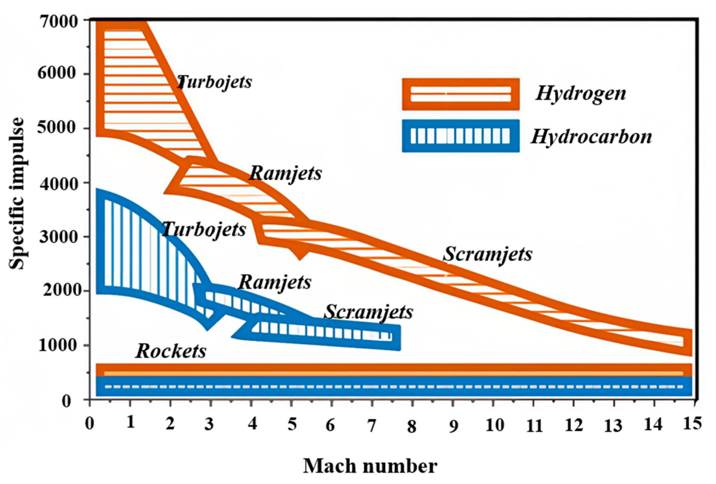
Figure 1. Relation of specific impulses of different engines to Mach number.
Aerospace 12 00351 g001
Figure 2. The SFSJ configuration proposed by Michacl A. Witt [11].
Aerospace 12 00351 g002
Figure 3. Witt et al.’s two-chamber engine structure [11].
Aerospace 12 00351 g003
Figure 4. Improved combustion chamber structure of Angus [13].
Aerospace 12 00351 g004
Figure 5. Improved combustion chamber structure of Ben-Yakar et al. [13,14].
Aerospace 12 00351 g005
Figure 6. SRSJ configuration diagram proposed by Lv Zhong et al. [16,17].
Aerospace 12 00351 g006
Figure 7. Combustion zones for different L/D ratios [33].
Aerospace 12 00351 g007
Figure 8. Schematic of cavity [33].
Aerospace 12 00351 g008
Figure 9. The engine structure diagram by Salgansky et al. [40].
Aerospace 12 00351 g009
Figure 10. Schematic diagram of the experimental device of Li Chaolong et al. [44].
Aerospace 12 00351 g010
Figure 11. The solid scramjet configuration [45].
Aerospace 12 00351 g011
Figure 12. Test engine schematic.
Aerospace 12 00351 g012
Figure 13. Detailed illustrations of the scramjet combustor flow path installed with a micro-rocket torch.
Aerospace 12 00351 g013
Figure 14. Numerical Schlieren (non-reacting) for different hydrogen flow rates with sonic and subsonic regions (M ≤ 1) colored. From top to bottom, PR = 0.25, PR = 0.50, and PR = 1. Position A represents the initial position of the isolation section, B represents the initial position of the combustion chamber, and C represents the end position of the combustion chamber.
Aerospace 12 00351 g014
Figure 15. Time-averaged flame luminosity images of all the cases.
Aerospace 12 00351 g015
Figure 16. Instantaneous images of combustion flow.
Aerospace 12 00351 g016
Figure 17. Schematic diagram of regenerative active cooling of a scramjet engine.
Aerospace 12 00351 g017
Figure 18. Gas film cooling schematic. The shaded part represents solid media. Red means high temperature, blue means low temperature.
Aerospace 12 00351 g018
Figure 19. Sweat cooling schematic.
Aerospace 12 00351 g019
Figure 20. Schematic diagram of the oxide layer during magnesium particle ignition.
Aerospace 12 00351 g020
Figure 21. Reaction mechanism of the BD ignition model for a single boron particle.
Aerospace 12 00351 g021
Table 1. Hybrid combustion enhancement methods for the liquid-fuel scramjet.
Physical MechanismMixing DevicePressure Loss EffectFlame Stabilization
Active hybrid enhancementLarge-scale forced incentivesVibrating splitter/wire [18]Smallno
Pulsed jet [19,20]Smallno
Helmholtz resonators [20]Smallno
Piezoelectric actuators [21]Smallno
Acoustic excitation [22]Smallno
Passive hybrid enhancementAcoustic excitation and flow vortex Cavities [22,23,24,25,26,27]SmallYes
Flow vortexPneumatic slope [28]SmallYes
Ramps [28]MediumYes
Self-excited resonance and flow vortexBackward-facing step [29]MediumYes
Flow vortex and Streamline orientationLobe mixers [21]Mediumno
Tabs [19]Largeno
Vortex breakdownVortex/shock interaction [21]Smallno
Twist flowSwirling Jets [21]Smallno
Oscillating structure excitationPort geometry [22]Smallno
Transverse curvatureTransverse injection [22]Smallno
Large-scale excitationShock/shear layer interaction [22]Smallno
Self-excited resonance and increased fuel working hoursCounterflow [22]Mediumno
Table 2. Advantages and disadvantages of four passive combustion intensifiers for scramjet engines.
Device TypeAdvantagesDisadvantages
Transverse jetFast near-field mixing and good fuel penetrationLarge total pressure loss and poor flame stability
Back stepThe placement position and quantity are more flexible, the total flow pressure loss is small, and the mixing effect is considerableThe influence range is small, the slope front heat load is large, and so on
Support plateBeneficial to improve the fuel distribution in the combustion chamber and reduce the heat load on the wallDirect placement in the high-speed flow field will bring greater internal resistance and total pressure loss, and the fuel is at the rear of the support plate; low-speed zone combustion heat release will bring an excessive heat load
CavitySimple structure, small total pressure loss, good stable combustion, etc., and can effectively promote fuel mixing
Table 3. Experimental cases in this study.
Test NumberFuelCavityEquivalence Ratio
1C2H4H90.34
2C2H4H90.39
3C2H4H90.50
4C2H4H90.35
5C2H4H90.40
6C2H4H90.51
Table 4. Comparison of the performance of scramjet engines using different fuels.
FuelArea (m2)Air Flow (kg.s−1)Density (kg.s−3)Specific Thrust (m.s−1)Specific Impulse (m.s−1)Density Specific Impulse
kg/(m2.s)
RP-3 80883112,1239.8 × 106
JP-70.042.8380685012,2109.84 × 106
solid 1600145397901.57 × 107
Table 5. Boron particle combustion process chemical equation.
Ignition ProcessCombustion Process
2 B2O3 (l) + 2B (s) → 3 B2O2 (g)2B (s) + O2 (g) → B2O2 (g)
B2O3 (l) → B2O3 (g)4B (s) + 2HO2 (g) +3O2 (g) → 4HBO2 (g)
4B (s) + 4B2O3 (l) + 6HO2 (g) + 3O2 (g) → 12HBO2 (g)B (l) → B (g)
Disclaimer/Publisher’s Note: The statements, opinions and data contained in all publications are solely those of the individual author(s) and contributor(s) and not of MDPI and/or the editor(s). MDPI and/or the editor(s) disclaim responsibility for any injury to people or property resulting from any ideas, methods, instructions or products referred to in the content.