Article

A Novel Self-Deployable Solar Sail System Activated by Shape Memory Alloys

by
Gianluigi Bovesecchi
1,†,
Sandra Corasaniti
1,†,
Girolamo Costanza
1,*,† and
Maria Elisa Tata
2,†
1
Industrial Engineering Department, University of Rome Tor Vergata, Via del Politecnico 1, 00133 Rome, Italy
2
Civil Engineering and Computer Science Department, University of Rome Tor Vergata, Via del Politecnico 1, 00133 Rome, Italy
*
Author to whom correspondence should be addressed.
These authors contributed equally to this work.
Aerospace 2019, 6(7), 78; https://doi.org/10.3390/aerospace6070078
Submission received: 30 April 2019 / Revised: 29 June 2019 / Accepted: 2 July 2019 / Published: 5 July 2019

Abstract

:
This work deals with the feasibility and reliability about the use of shape memory alloys (SMAs) as mechanical actuators for solar sail self-deployment instead of heavy and bulky mechanical booms. Solar sails exploit radiation pressure a as propulsion system for the exploration of the solar system. Sunlight is used to propel space vehicles by reflecting solar photons from a large and light-weight material, so that no propellant is required for primary propulsion. In this work, different small-scale solar sail prototypes (SSP) were studied, manufactured, and tested for bending and in three different environmental conditions to simulate as much as possible the real operating conditions where the solar sails work. Kapton is the most suitable material for sail production and, in the space missions till now, activated booms as deployment systems have always been used. In the present work for the activation of the SMA elements some visible lamps have been employed to simulate the solar radiation and time-temperature diagrams have been acquired for different sail geometries and environmental conditions. Heat transfer mechanisms have been discussed and the minimum distance from the sun allowing the full self-deployment of the sail have also been calculated.

Graphical Abstract

1. Introduction

Solar sails exploit the light of the sun as a propulsion system [1]. This propulsion system does not need any chemical propellant for imparting motion in the space. Quantum packets of energy (solar radiation pressure) to propel a spacecraft are the basic concept for these devices [2,3]. Thanks to the interaction of a great number of photon in the sunshine light with the solar sail, a small radiation pressure is produced on the sail itself [4,5]. Due to the small pressure level, in order to exploit this propulsion system, a great surface of the sail is required. For the same reason materials employed for the construction of the sail must show low weight and high reflectivity [6]. Engines based on ion propulsion for small satellites are able to work according to the principle that a small but constant pressure applied on a wide surface of the sail can produce a satisfying acceleration to the whole structure [7].
In the following, the main space missions on this theme are reported:
1973: Mariner 10 (NASA): radiation pressure has been employed for the attitude control [8];
1999: Odyssee project (DLR-ESA): laboratory deployment test [9];
2010: Ikaros (JAXA): first space probe employing successfully satellite solar sails propulsion up to Venus [2,10];
2011: Nanosail-D2 (NASA): applicability study of the solar-sail propulsion to small satellites [11];
2015: Lightsail-1 (Planetary Society): solar sail totally deployed without reaching the orbit [12].
A novel approach for controlling solar sail using the reflectivity modulation technology, which was originally designed to adjust the attitude of the solar sail, was proposed by Mu et al. [13]. Many different systems have been, until now, considered for the sails opening. Each system is characterized by the presence of guide rollers, electromechanical actuation devices or composite booms [14,15]. In the actual deployment technology, the main limit is the high weight of the system and the complexity of the deployment mechanism for such huge surfaces. The objective for the present work is to study and test different small-scale solar sail prototypes (SSPs) in three different environmental conditions to simulate as much as possible the real operating conditions of the solar sails.
A self-deploying system based on NiTi shape memory alloy (SMA) wires has been designed and manufactured in a small-scale prototype. Kapton has always been employed as sail surface with a thin Al coating [16,17], and has been illustrated in detail in previous works [18,19]. In our experiments commercial pure Al thin sheets in addition with adhesive kapton film have been used in order to simulate the sail.
In the deployment experiments the attention has been focused on the effect of different environmental conditions on the activation performances. About the heating method halogen lamps have been employed in order to obtain the self-deployment of the sail.

2. Materials and Sail Prototype Geometry

For what concerns the active elements, a nitinol shape memory alloy wire with a diameter of 0.41 mm was used. Shape memory alloys are smart materials which can recover the pre-set shape just by heating above the critical transformation temperature. In order to set the shape a particular thermal treatment has been identified, usually called shape-setting. It consists in heating up to 500 °C while the wire is kept straight on a flat bed, maintaining at this temperature for 5 min, and finally quenching in cold water. After this treatment, bent in cold conditions (room temperature or lower), the wire is able to recover the preset straight shape just upon heating above the activation temperature (65–95 °C), depending on the selected alloy (composition and thermal history of the wire) [20]. The activation temperature is not only a function of the composition of the selected alloy, but also of the thermal and mechanical history of the material, described in detail in a previous work [21]. If properly designed shape memory alloys can also bear high number of activation cycles [22]. An alternative solution regarding the positioning of the SMA active elements not straight on the sail surface, but on a carbon-fiber frame of the sail has been investigated in the past, with positive results in terms of planarity of the deployed sail but with the drawbacks due to the higher weight of the whole system [23].
The sail prototype described in the present work has been made of thin commercial aluminum films (12 μm, 2.7 g/cm3). The sail sub-layer has been covered by thin films (2.5 μm) of adhesive kapton (1.4 g/cm3). Aluminum has been chosen for the high reflectivity in the whole solar spectrum and the relatively high melting point and Kapton because is chemically inert, shows a high mechanical strength subjected to sunlight radiation and maintains stable its physical and chemical properties also at high temperature and if exposed to solar radiation.
In order to fix the wires over the kapton sail a silicone resistant to high temperature as gluing material has been used with aluminum sheet on top. Nitinol wires perpendicularly to the bending line have been placed.
Two SSP configurations with different number and wires positioning have been investigated and reported below. The SSP schemes are detailed in Figure 1 and Figure 2. In both cases the SSP was an isosceles triangle-shape with a base of 200 mm and the height of 100 mm. With the same sail surface and geometry, respectively 11 and 12 shape memory wires were employed. As pointed out in a previous work [24] the sail planarity after deployment is strictly correlated to the wires positioning and length.

2.1. Sail Configuration 1 (SC1)

The surface of sail configuration 1 (SC1) is 100 cm2 and 12 SMA wires (0.41 mm diameter) have been employed (two 30 mm length, ten 20 mm length). Sketch and prototype are reported in Figure 2.

2.2. Sail Configuration 2 (SC2)

The surface of sail configuration 2 (SC2) is 100 cm2 and 11 SMA wires (0.41 mm diameter) were employed (one 30 mm length, two 40 mm length and eight 20 mm length). Sketch and prototype are reported in Figure 3.

2.3. Folding Methods

Reported below are the two different folding configurations that were applied to the sail. The radius of curvature of each wire was limited to 2 mm during the folding stage in order to avoid residual strain in the martensitic phase.

2.4. Folding Configuration 1 (FC1)

The folding sequence was based on five deployments on the same side of the SSP. The final surface of the packed SSP was 25% compared with the deployed one. Folding configuration 1 (FC1) was carried out on SC1 (Figure 4).

2.5. Folding Configuration 2 (FC2)

Similarly to FC1, this folding method is based on five deployments, the first one of which is made on the opposite side of the SMA and the following four on the same side of the sail, as shown in Figure 5. The final surface of the packed SSP was 25% compared with the deployed one. The FC2 was carried out on SC1 and SC2 (Figure 5).

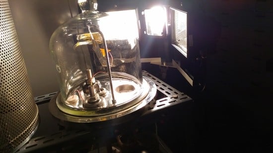
3. Experimental Set-Up and Conditions

The experimental apparatus was built-up and employed to simulate in the laboratory environmental conditions in orbit, for SSP deployment tests (Figure 6) and was composed of:
(1)
Bell jar;
(2)
Photodiode;
(3)
Thermocouples;
(4)
Pressure transducer;
(5)
Lighting system;
(6)
Vacuum (rotary) pump.
The SSP was placed inside the bell jar which allowed us to change the test pressure with a vacuum pump up to about 0.06 mbar. By means of a photodiode the glass attenuation coefficient was evaluated to be equal to 4.7%, so that about 95% of the incident radiation coming from the lamps can be considered applied to the sail. To monitor environment temperature in the bell jar and on the SSP, two thermocouples were employed. Both thermocouples were placed in the opposite side with respect to the incident radiation. The lighting system was composed by three visible lamps for a total power of 1.8 kW. Concerning the deployment conditions, tests 1 and 2 were performed under the same pressure (1000 mbar), fluid (air), and folding method on two different sail configurations (SC1 and SC2). The main purpose of this test was to define the best positioning of the SMA active elements on the SSP studied, identified in SC2. Hereafter only SC2 was considered for the successive comparisons. In test 3 the same configuration sail (SC2) was tested but with the folding sequence called SC2, in which, the first folding is applied on the external side of the sail (Figure 5). In the test 4 (SC2 and FC2) the effect of the atmosphere has been evaluated replacing air with Argon (lower specific heat than air) at the atmospheric pressure. Finally test 5 (see video attached in the Supplementary Materials) was carried out in low pressure conditions (0.06 mbar) achieved by means of a rotary pump, as similar as possible to the vacuum condition in orbit. In Table 1 the test conditions are summarized.

4. Results and Discussion

Time-temperature trends acquired by the thermocouple on the sail in the deployment tests of SSP in different environmental conditions (tests 1 to 5) are reported in Figure 7. The recorded temperature was acquired by the thermocouple placed inside the SSP, in contact with it, on the opposite side with respect to the lighted surface. For each test carried out in the bell-jar, under different environmental conditions, temperature vs time trends were video-recorded and successively analyzed by an operator. As evidenced in Figure 8 as an example, in order to identify the Opening time Start (O.t.S.), the Opening time Finish (O.t.F.), the Opening Temperature Start (O.T.S.), and the Opening Temperature Finish (O.T.F.), red vertical and horizontal lines have been reported in correspondence of start and end of opening of the sail self-activated by the shape memory wires. Different values of times and temperatures for each test conditions are reported in Table 2.
In Figure 7 the comparison between all the tests, performed under the same radiative conditions, is reported. For all the tests the initial temperature was 20 °C. In the range 0–100 s the slope of the curve raised from test 1 to test 5, due to different positioning of the actuators, folding method and employed fluids. Figure 7 reports the sail temperature in three different environments and it is possible to observe that in the case of low pressure, the range of quasi-linear trend for short times was longer than in the argon and air environments. This allowed reaching the opening of the sail in less time than the other two cases because the heat could be transferred in different ways. When inside the bell a gas was present, the heat generated by the visible lamp and transferred by irradiation was lost due to the thermal convection between gas, bell-jar and the sail itself.
The following table shows the results in terms of opening times and temperatures for different atmospheres (air, argon, or low pressure) and folding methods. Each deployment test was performed three times in order to monitor also the repeatability of the process and the average values have been reported in Table 2.
From analysis of Figure 7 the following considerations can be summarized:
In the comparison between test 1 and test 2, SC2 showed shorter times (850 s vs. 1127 s in terms of O.t.F.) due to the better positioning of the actuators compared to SC1.
In the comparison between test 2 and test 3, reduction in terms of O.t.F. can be due to the different folding configurations (some actuators facing the radiation in FC2).
In the comparison between test 3 (air) and test 4 (Ar), a remarkable reduction of the O.t.S. and O.t.F. was measured, about −30% for both of them, due to the lower thermal capacity of Ar.
In the comparison between test 3 and test 5, the greatest reduction of the O.t.S., O.t.F. was measured. In particular −75% for O.t.S., −95% for O.t.F., due to the different heat transfer mechanisms. In test 3, thermal convection and radiation was dominant, while in test 5, the main heat transfer mechanism was thermal radiation.
Synthesizing, the heat received by the sail is composed by two main components: the thermal radiation that comes from the lighting system, which is reflected towards the glass, and the thermal radiation that comes from the lighting system, is absorbed, and then re-emitted from the glass.
The heat losses depend on: the absorbed heat by the glass, then exchanged by convection with the gas inside the bell, and the convective heat transfer between the sail itself and the gas inside the bell.
In order to investigate the heat transfer mechanisms and evaluate the different components the fluid temperature inside the bell has been recorded with a suitably shielded thermocouple in a test. In Figure 9, the temperature trends in sail and air in a typical test are reported. The sail temperature was always higher than the fluid temperature, and so convective heat flux occurred from sail to fluid.
The heat exchanged from air is given by:
Q = m a c p a Δ T a
where cpa is the air specific heat equal to 1008 J/kgK, ΔTa is the temperature difference between the end and the start of the sail opening, ma is the air mass in the glass bell given by m a = ρ a V a = 0.01737 kg , with ρ a = 1.193 kg / m 3 and V a = 0.009 m 3 .
The absorbed heat is equal to the energy loss from the sail due to natural convection and thermal radiation. The convective heat is equal to:
Q = h A Δ T Δ t
where h is the convective heat transfer coefficient, A is twice the sail surface, ΔT is the temperature difference between the sail and fluid, and Δt is the time lapse.
The convective heat transfer coefficient is
h = N u L k L
where k is the fluid thermal conductivity, NuL is the average Nusselt number, in natural convection given by empirical correlation [20]
N u L = 0.57 G r L Pr 0.25 = 0.57 g β Δ T L 3 ν 2 Pr 0.25
where GrL is the Grashof number, Pr Prandtl number, β is the fluid thermal expansion coefficient, ν is the fluid kinematic viscosity, g is the gravity acceleration, ΔT is the temperature difference between sail and fluid, and L is the sail characteristic length.
In Table 3, the expressions of convective heat transfer coefficient evaluated with Equation (3) for T = 20 °C and T = 60 °C are reported.
For both temperatures, the argon convective coefficient is always lower than air. In low pressure conditions inside the bell the convective heat transfer can be neglected and the only heat exchange occurs by radiation. For this reason in tests performed at low pressure, shorter times have been required for the SMA to reach the activation temperature. Low pressure environment is the operating condition closer to the solar sails working in the space. The energy balance of the sail in the space is [25]
σ T 4 ε f + ε b = 1 r G s R s d 2 cos α
where σ is the Stefan-Boltzmann constant (5.67 × 10⁻⁸ W m−2 K−4), εf and εb are the front and back surface emissivity, respectively, r is the sail solar reflectance, Gs is the solar constant, Rs is the earth-sun distance, d is the sail-sun distance, and α is the sail pitch angle.
From Equation (5) the sail temperature depending on sun distance (RE) can be obtained:
T = 1 r ε f + ε b G s σ R s d 2 cos α 0.25
If Equation (6) is applied to the case studied in laboratory it is possible to evaluate the minimum distance d (Equation (7)) between sail and sun necessary to reach the SMA activation temperature allowing the self-deployment.
d = R s G s 1 r σ T 4 ε f + ε b cos α 0.5
where r = 0.85 aluminum reflectance, T sail temperature, cos α 1, εf 0 (for aluminum), εb = 0.34 (for Kapton).
From Equation (7), the range of 45 °C < T < 95 °C is the minimum distance (d) to reach the SMA activation temperature which comprised within the range 1.08 UA > d > 0.81 UA. Shape memory alloys with lower activation temperatures, if required, are commercially available in order to allow the full self-activation of the sail at the distance of the sun to earth.

5. Conclusions

In this work the feasibility and different ways to simplify the opening of a solar sail prototype has been studied. Differently from electromechanical systems currently in use, SMA has advantages due to considerable economic savings during launch due to their lower weight in comparison with standard solar sails, composed of frame, booms and engines, and at the same time, simplicity of the system. Conclusions of earlier studies focused on the length and arrangement of the alloy actuators here were optimized. Some prototypes have been manufactured and tested for self-deployment under light irradiation inside of a bell-jar. Also the environmental conditions inside the bell-jar were studied experimentally to monitor the opening of the sail. Shorter opening times for the sail have been achieved employing gas with low specific heat or reducing the fluid pressure inside the bell-jar, in order to minimize heat losses. The experimental results have confirmed that the lower the pressure, the shorter the sail activation times. At lower pressures, the convective heat mechanism was negligible with respect to the thermal radiation. Finally the behavior in the real opening conditions of the prototype was simulated, and the minimum distance from the sun allowing the self-deployment of the sail has been determined. Results of this work show the great potential of shape memory alloys in aerospace applications. Shape memory alloys do not suffer exposition to lower temperatures, but the phase transformation while heating to the transformation temperature should be taken into account and, if necessary, avoided. Deployment tests after TVAC (Thermal Vacuum Testing) would be extremely important in a subsequent development test (bigger sail) before performing experiments in orbit.

Supplementary Materials

The following are available online at https://www.mdpi.com/2226-4310/6/7/78/s1, Video S1: SSP deployed in air, 0.06 mbar.

Author Contributions

Equal contributions from all authors.

Funding

This research did not receive any specific grant from funding agencies in the public, commercial, or not-for-profit sectors.

Acknowledgments

Authors are grateful to Piero Plini and Benedetto Iacovone for technical support during the experiments.

Conflicts of Interest

The authors declare no conflict of interest.

References

  1. Tsiolkowsky, K.E. Extension of Man into Outer Space. Proc. Symp. Jet Propuls. 1921, 2. [Google Scholar]
  2. Tsuda, Y.; Mori, O.; Funase, R.; Sawada, H.; Yamamoto, T.; Saiki, T.; Endo, T.; Kawaguchi, J. Flight status of IKAROS deep space solar demonstrator. Acta Astronaut. 2011, 69, 833–840. [Google Scholar] [CrossRef]
  3. Niccolai, L.; Anderlini, A.; Mengali, G.; Quarta, A.A. Impact of solar sail wind fluctuations on electric sail mission design. Aerosp. Sci. Technol. 2018, 82, 38–45. [Google Scholar] [CrossRef]
  4. Leipold, M.; Eiden, M.; Garner, C.E.; Herbeck, L.; Kassing, D.; Niederstadt, T.; Kruger, T.; Pagel, G.; Rezazad, M.; Rozemejjer, H.; et al. Solar sail technology development and demonstration. Acta Astronaut. 2003, 52, 317–326. [Google Scholar] [CrossRef]
  5. Colin, R. Solar Sailing: Technology, Dynamics and Mission Applications; Springer Science and Business Media: Berlin, Germany, 2004. [Google Scholar]
  6. Block, J.; Straubel, M.; Wiedemann, M. Ultralight deployable booms for solar sails and other large gossamer structures in space. Acta Astronaut. 2011, 68, 984–992. [Google Scholar] [CrossRef]
  7. Johnson, L.; Young, R.; Montgomery, E.; Alhorn, D. Status of solar sail technology within NASA. Adv. Space. Res. 2011, 48, 1687–1694. [Google Scholar] [CrossRef] [Green Version]
  8. Mariner 10, NASA. National Space Science Data Center (NSSDC). Available online: https://nssdc.gsfc.nasa.gov/nmc/spacecraft/display.action?id=1973-085A (accessed on 3 July 2019).
  9. Leipold, M.; Garner, C.E.; Freeland, R.; Herrmann, A.; Noca, M.; Pagel, G.; Sebolt, W.; Sprague, G.; Unckenbold, W. Odissee—A proposal for demonstration of a solar sail in earth orbit. Acta Astronaut. 1999, 45, 557–566. [Google Scholar] [CrossRef]
  10. Mori, O.; Sawada, H.; Funase, R.; Endo, T.; Morimoto, M.; Yamamoto, T.; Tsuda, Y.; Kawakatsu, Y.; Kawaguchi, J. Development of first Solar Power Sail Demonstrator—Ikaros. In Proceedings of the 21st International Symposium on Space Flight Dynamics, Toulouse, France, 28 September–2 October 2009. [Google Scholar]
  11. Johnson, L.; Whorton, M.; Heaton, A.; Pinson, R.; Laue, G.; Adams, C. NanoSail-D: A solar sail demonstration mission. Acta Astronaut. 2011, 68, 571–575. [Google Scholar] [CrossRef] [Green Version]
  12. Nehrenz, M.; Diaz, A.; Svitek, T.; Biddy, C. Initial design and simulation of the LightSail-1 attitude determination and control system. In Proceedings of the 2nd International Symposium on Solar Sailing, New York, NY, USA, 20–22 July 2010; pp. 135–140. [Google Scholar]
  13. Mu, J.; Gong, S.; Li, J. Reflectivity-controlled solar sail formation flying for magnetosphere mission. Aerosp. Sci. Technol. 2013, 30, 339–348. [Google Scholar] [CrossRef]
  14. Fernandez, J.M.; Lappas, V.J.; Daton-Lovett, A.J. Completely stripped solar sail concept using bi-stable reeled composite booms. Acta Astronaut. 2011, 69, 78–85. [Google Scholar] [CrossRef]
  15. Fu, B.; Eke, F. Further investigation of the body torques on a square solar sail due to the displacement of the sail attachment points. Aerosp. Sci. Technol. 2016, 50, 281–294. [Google Scholar] [CrossRef]
  16. Roman Kezera, Y.A. Thickness requirement for solar sail foils. Acta Astronaut. 2009, 65, 507–518. [Google Scholar]
  17. Dalla Vedova, F.; Henrion, H.; Leipold, M.; Girot, T.; Vaudemont, R.; Belmonte, T.; Fleury, K.; Le Couls, O. The Solar Sail Materials (SSM) Project—Status of activities. Adv. Space Res. 2011, 48, 1922–1926. [Google Scholar] [CrossRef]
  18. Costanza, G.; Tata, M.E. Design and characterization of a small-scale solar sail deployed by NiTi Shape Memory Actuators. Procedia Struct. Integr. 2016, 2, 1451–1456. [Google Scholar] [CrossRef]
  19. Costanza, G.; Tata, M.E. A novel methodology for solar sail opening employing shape memory alloy elements. J. Intell. Mater. Syst. Struct. 2018, 29, 1793–1798. [Google Scholar] [CrossRef]
  20. Costanza, G.; Tata, M.E.; Libertini, R. Effect of temperature on the mechanical behavior of Ni-Ti Shape Memory Sheets. In Proceedings of the TMS2016 145th Annual Meeting Supplemental Proceedings, Nashville, TN, USA, 14–18 February 2016; pp. 433–439. [Google Scholar]
  21. Costanza, G.; Paoloni, S.; Tata, M.E. IR thermography and resistivity investigations on Ni-Ti shape memory alloys. Key Eng. Mater. 2014, 605, 23–26. [Google Scholar] [CrossRef]
  22. Costanza, G.; Tata, M.E.; Calisti, C. Nitinol one-way shape memory springs: Thermomechanical characterization and actuator design. Sens. Actuators A Phys. 2010, 157, 113–117. [Google Scholar] [CrossRef]
  23. Costanza, G.; Leoncini, G.; Quadrini, F.; Tata, M.E. Design and characterization of a small-scale solar sail prototype by integrating NiTi SMA and carbon fibre composite. Adv. Mater. Sci. Eng. 2017, 2017, 8467971. [Google Scholar] [CrossRef]
  24. Bottini, L.; Boschetto, A.; Costanza, G.; Tata, M.E. Shape memory activated self deployable solar sails: Small-scale prototypes manufacturing and planarity analisys by 3D Laser Scanner. Actuators 2019, 8, 38. [Google Scholar]
  25. Kezerashvili, R.Y. Solar Sail: Materials and Space Environmental Effects. In Solar Sail; Springer: Berlin, Germany, 2014; pp. 573–592. [Google Scholar] [Green Version]
Figure 1. Sketch of solar sail prototype (SSP) with bending lines (dashed).
Aerospace 06 00078 g001
Figure 2. (a) Sketch of sail configuration 1 (SC1): bending lines and shape memory alloys (SMAs) positioning (red line) are reported. (b) Photograph of Al-kapton SSP with SMA elements placed on the bending lines.
Aerospace 06 00078 g002
Figure 3. (a) Sketch of sail configuration 2 (SC2): bending lines and shape memory alloy SMA positioning (red line) are reported. (b) Photograph of Al-kapton SSP with SMA elements placed on the bending lines.
Aerospace 06 00078 g003
Figure 4. From left to right the folding configuration 1 (FC1) sequence is reported (front view).
Aerospace 06 00078 g004
Figure 5. From left to right, folding configuration 2 (FC2) sequence is reported.
Aerospace 06 00078 g005
Figure 6. Experimental apparatus.
Aerospace 06 00078 g006
Figure 7. Sail temperature versus time in the tests 1–5 (comparison).
Aerospace 06 00078 g007
Figure 8. Sail temperature versus time in test 1 of Table 2 (Air—SC1 FC1).
Aerospace 06 00078 g008
Figure 9. Comparison between sail and air 1 bar temperature in a typical test.
Aerospace 06 00078 g009
Table 1. Sail configurations, environmental conditions and folding methods adopted for the experiments.
TestSailFluidPressure
(mbar)
Folding Method
1SC1Air1000FC1
2SC2Air1000FC1
3SC2Air1000FC2
4SC2Argon1000FC2
5SC2Air0.06FC2
Table 2. Environmental conditions, folding method, opening time start and finish, opening temperature start, and finish for the SSPs tested.
TestSailFluidPressure
(mbar)
Folding MethodO.t.S.
(s)
O.t.F.
(s)
O.T.S.
(°C)
O.T.F.
(°C)
1SC1Air1000FC120112750.088.0
2SC2Air1000FC12085053.084.2
3SC2Air1000FC22084253.288.8
4SC2Argon1000FC21460151.085.1
5SC2Air0.06FC254626.081.0
O.t.S. = Opening time Start; O.t.F. = Opening time Finish; O.T.S. = Opening Temperature Start; O.T.F. = Opening Temperature Finish.
Table 3. Convective heat transfer coefficient for air and argon at two different temperatures.
Fluidh (20 °C)h (60 °C)
Air1.52ΔT1/4L41.46ΔT1/4L4
Ar1.08ΔT1/4L41.03ΔT1/4L4

