
New Thermal Design Strategy to Achieve an 80-kg-Class Lightweight X-Band Active SAR Small Satellite S-STEP

 ,
,  ,
, 
Abstract
1. Introduction
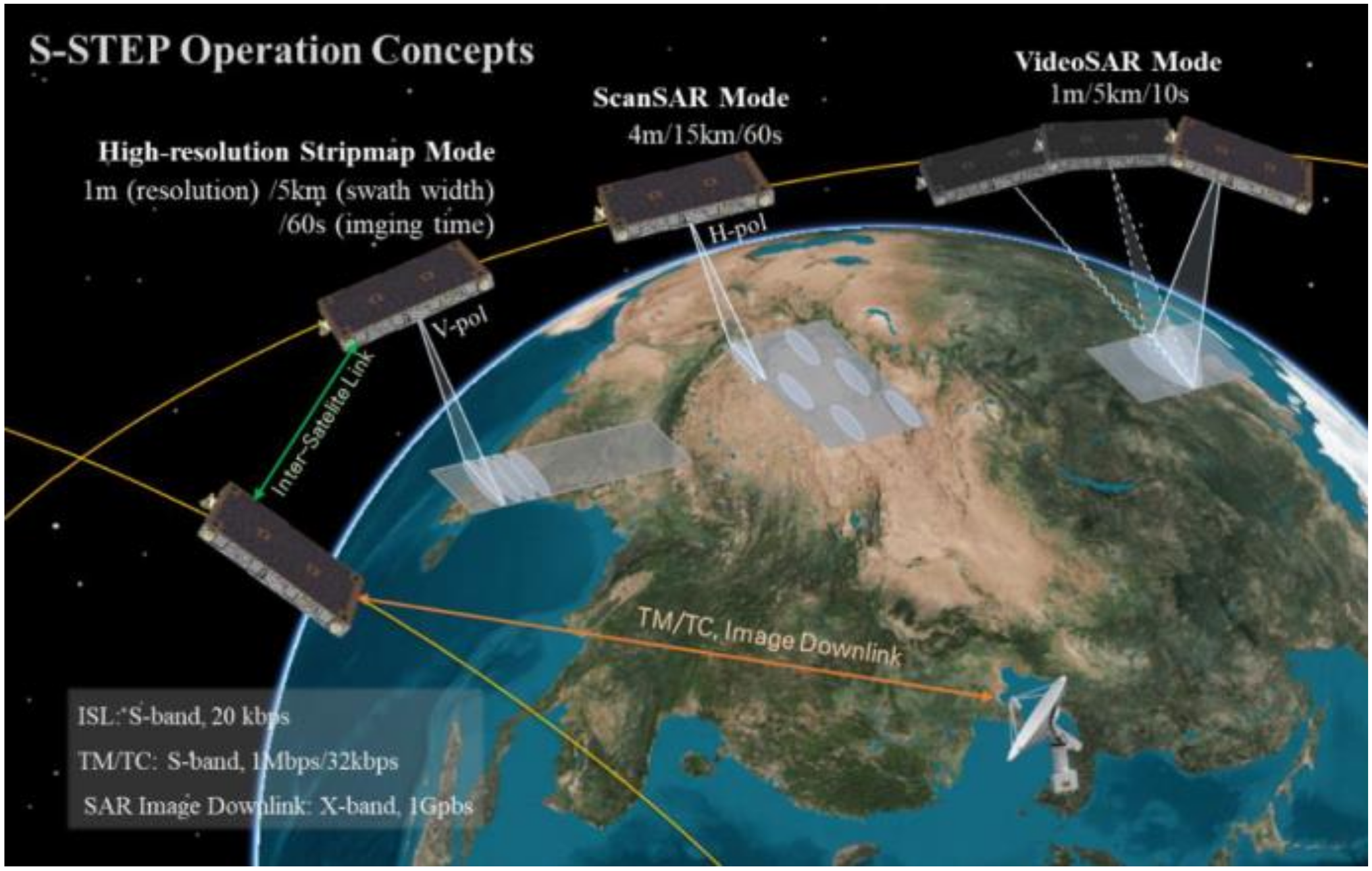
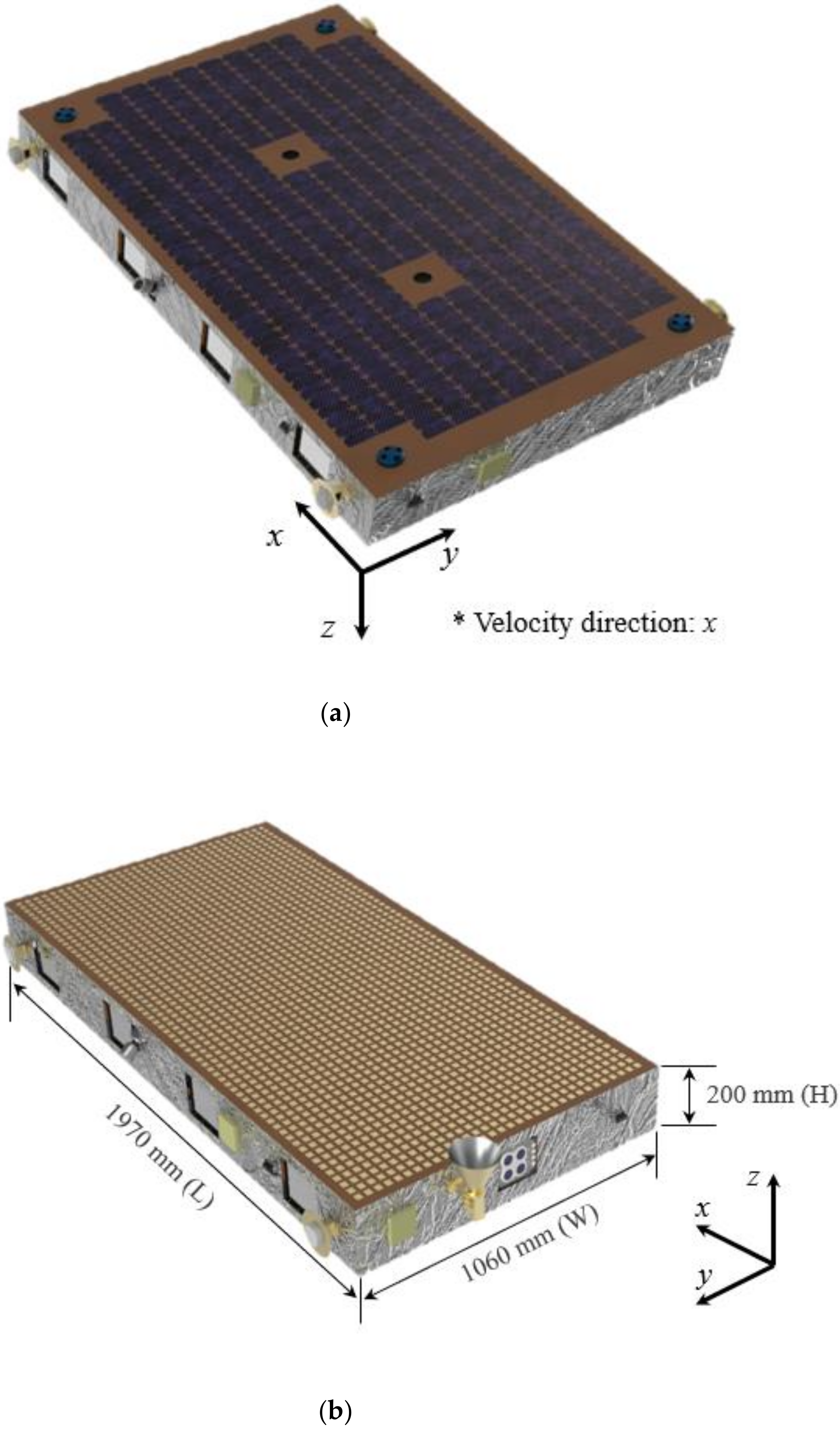
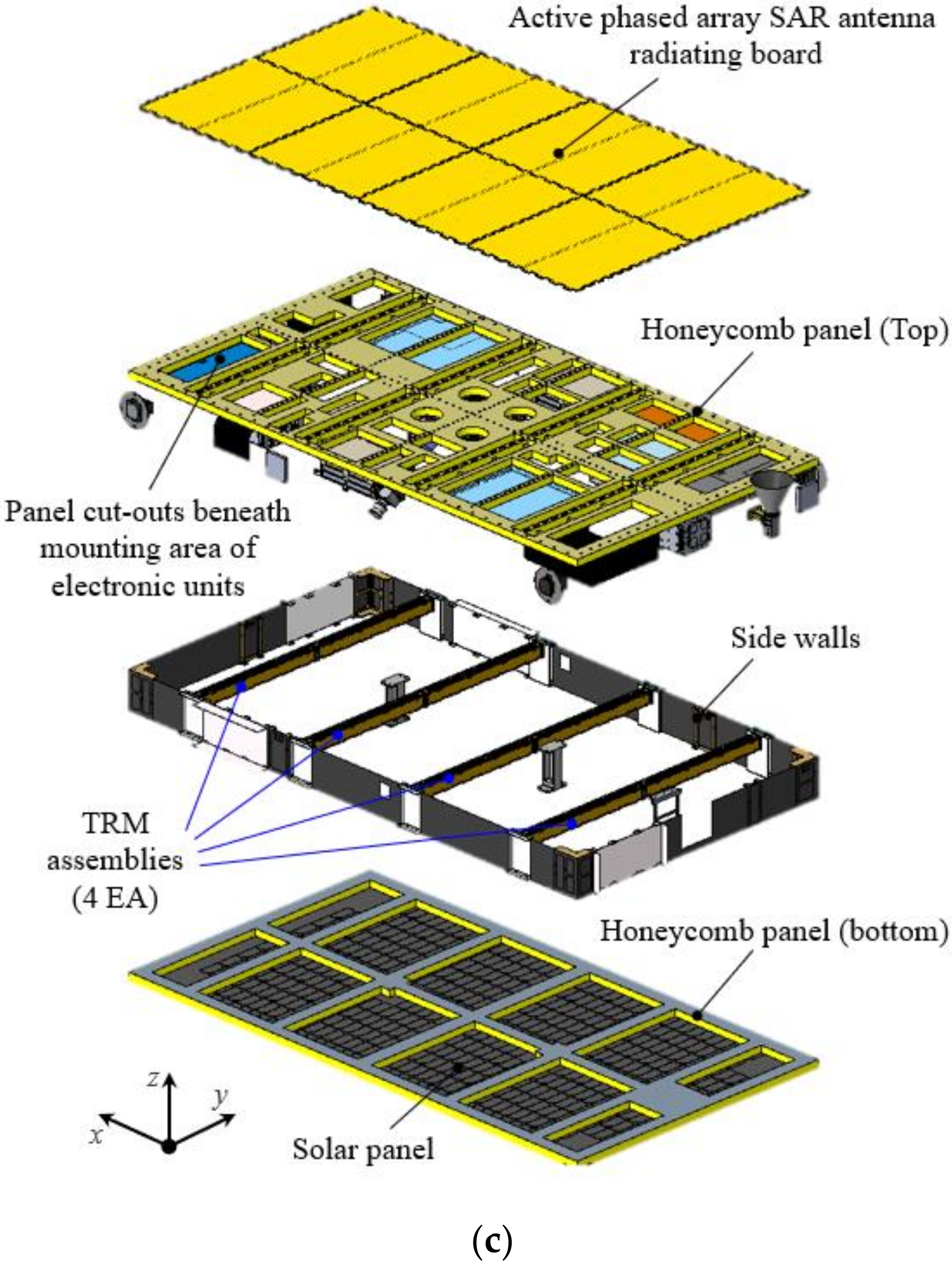
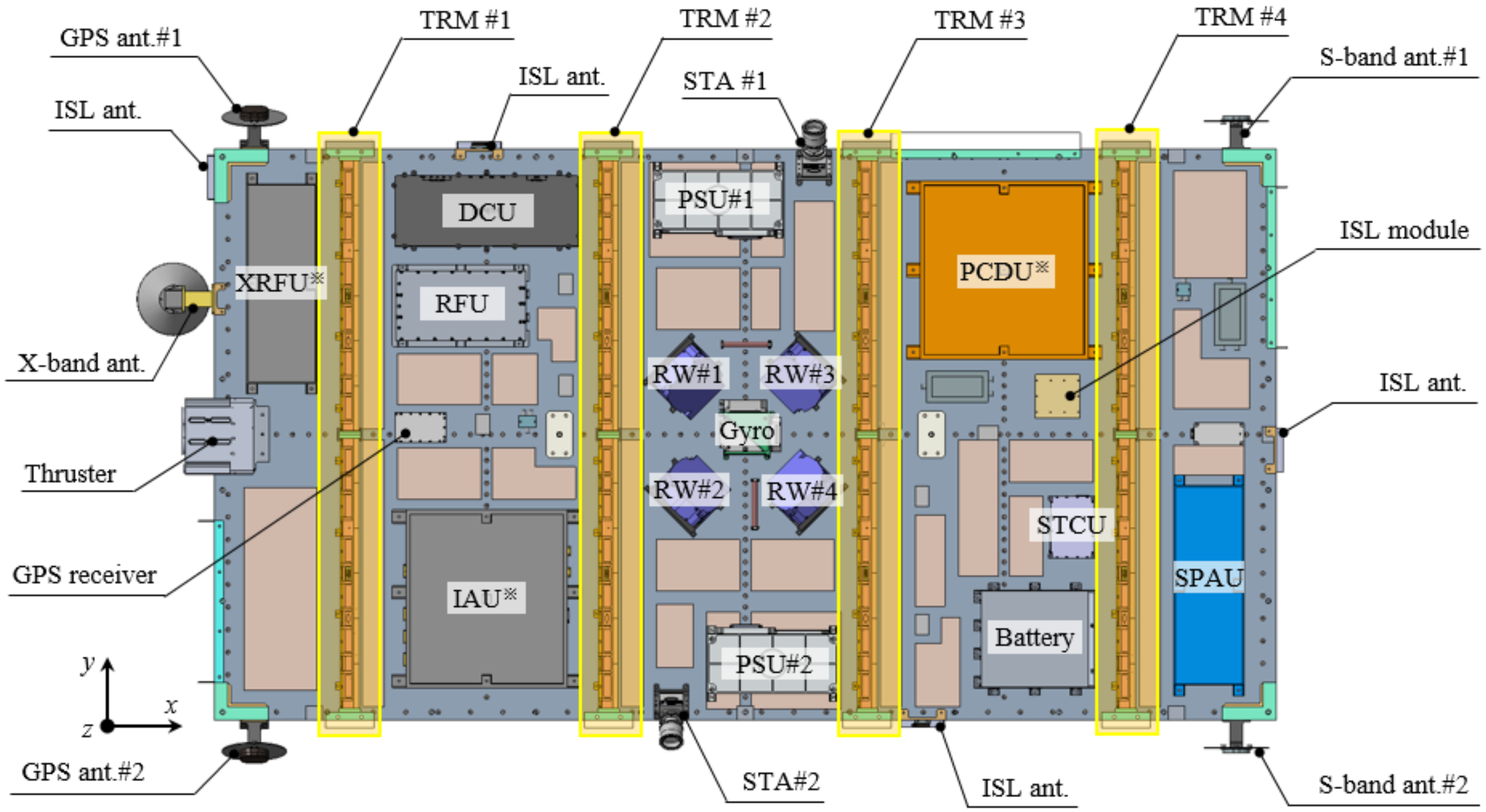
2. S-STEP System Overview
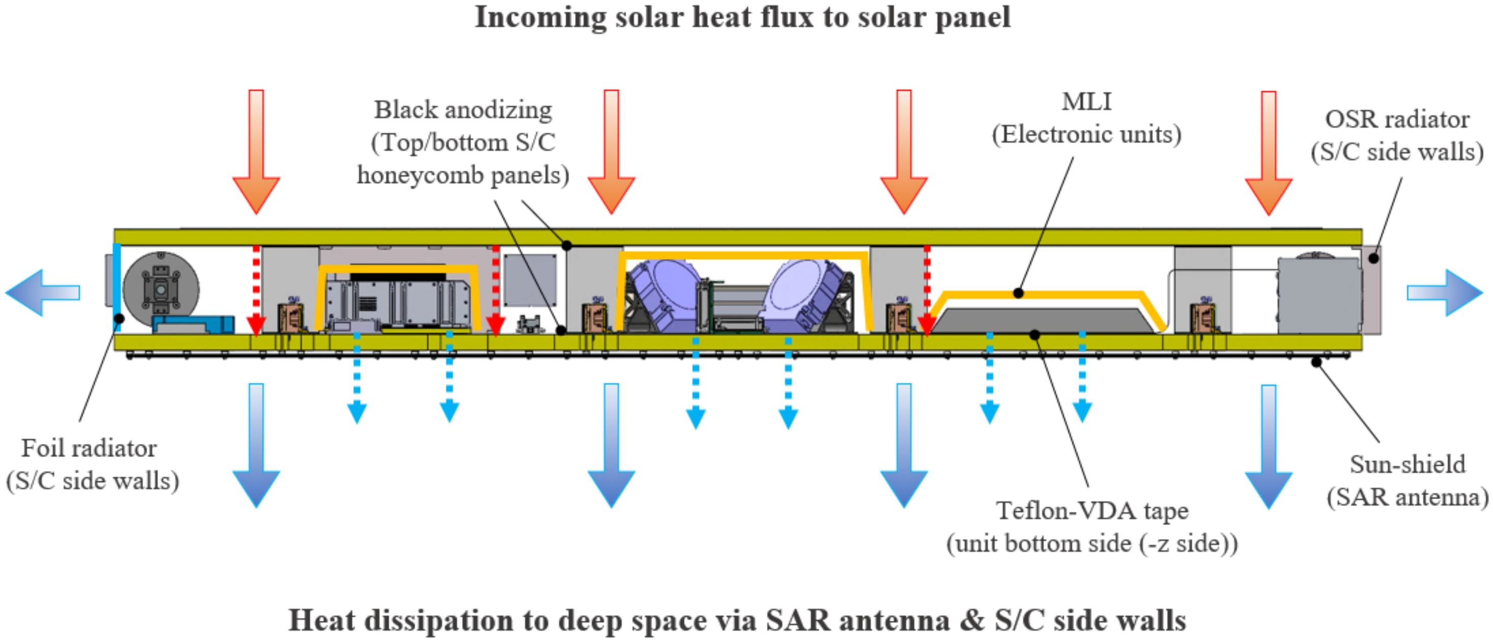
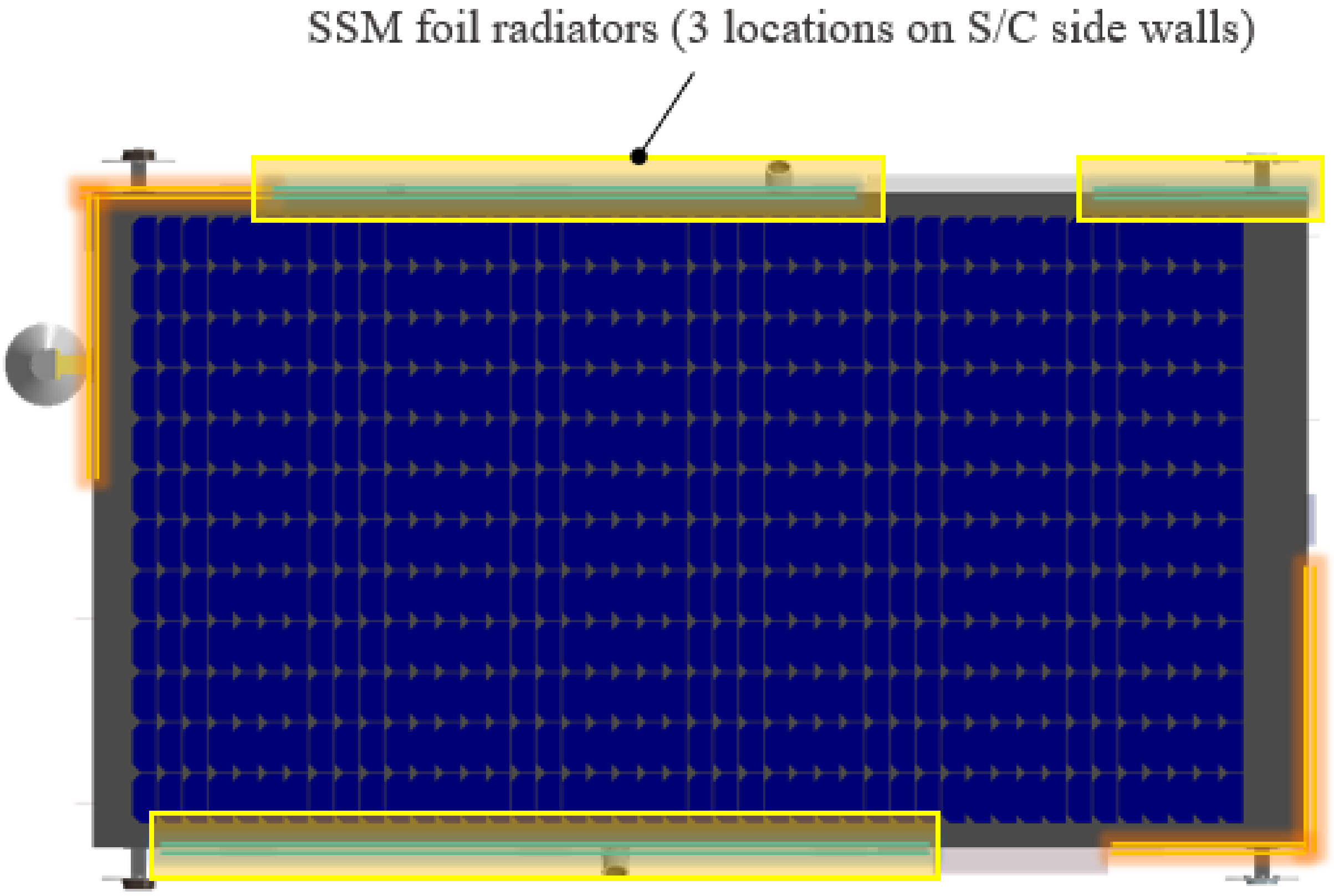
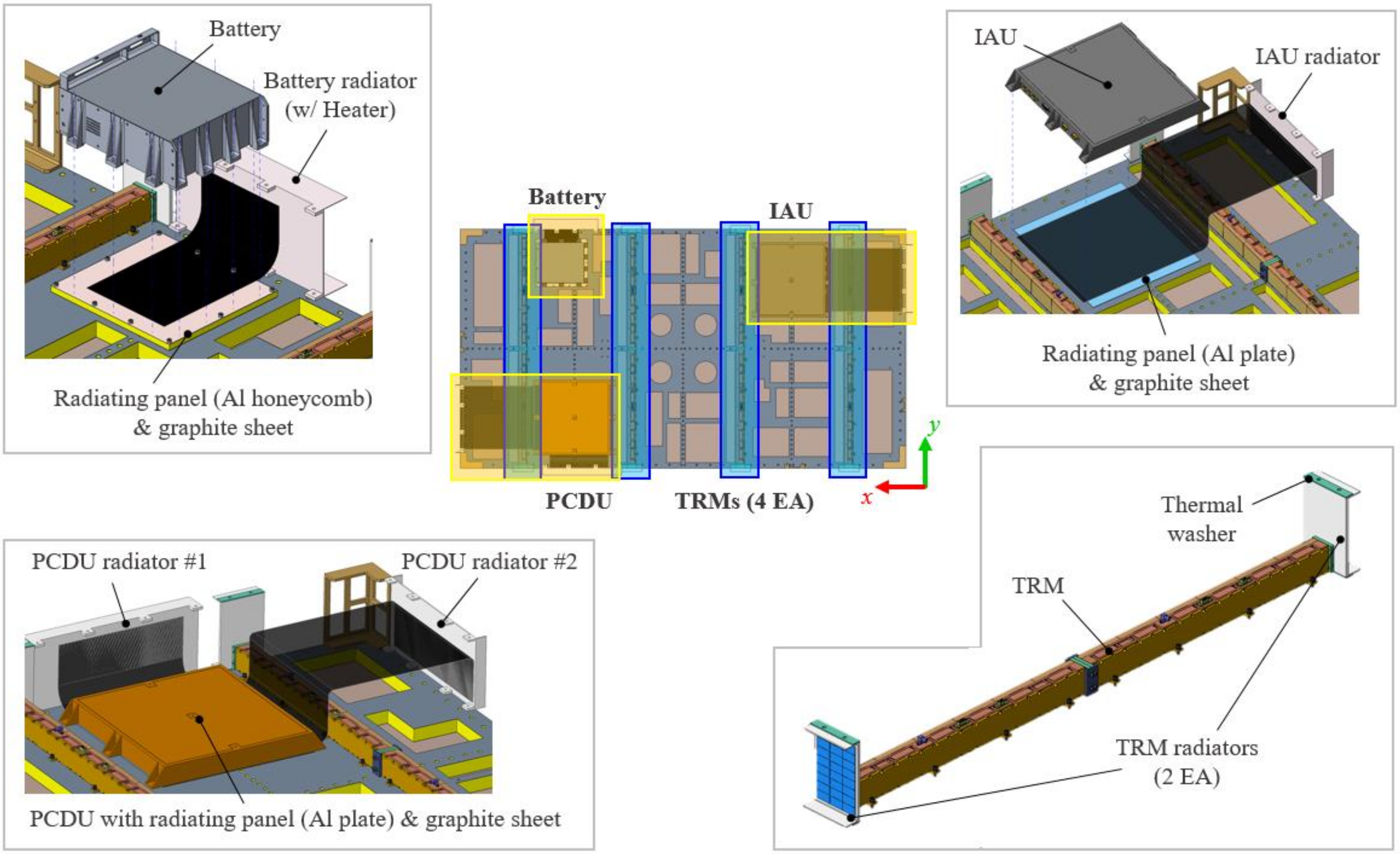
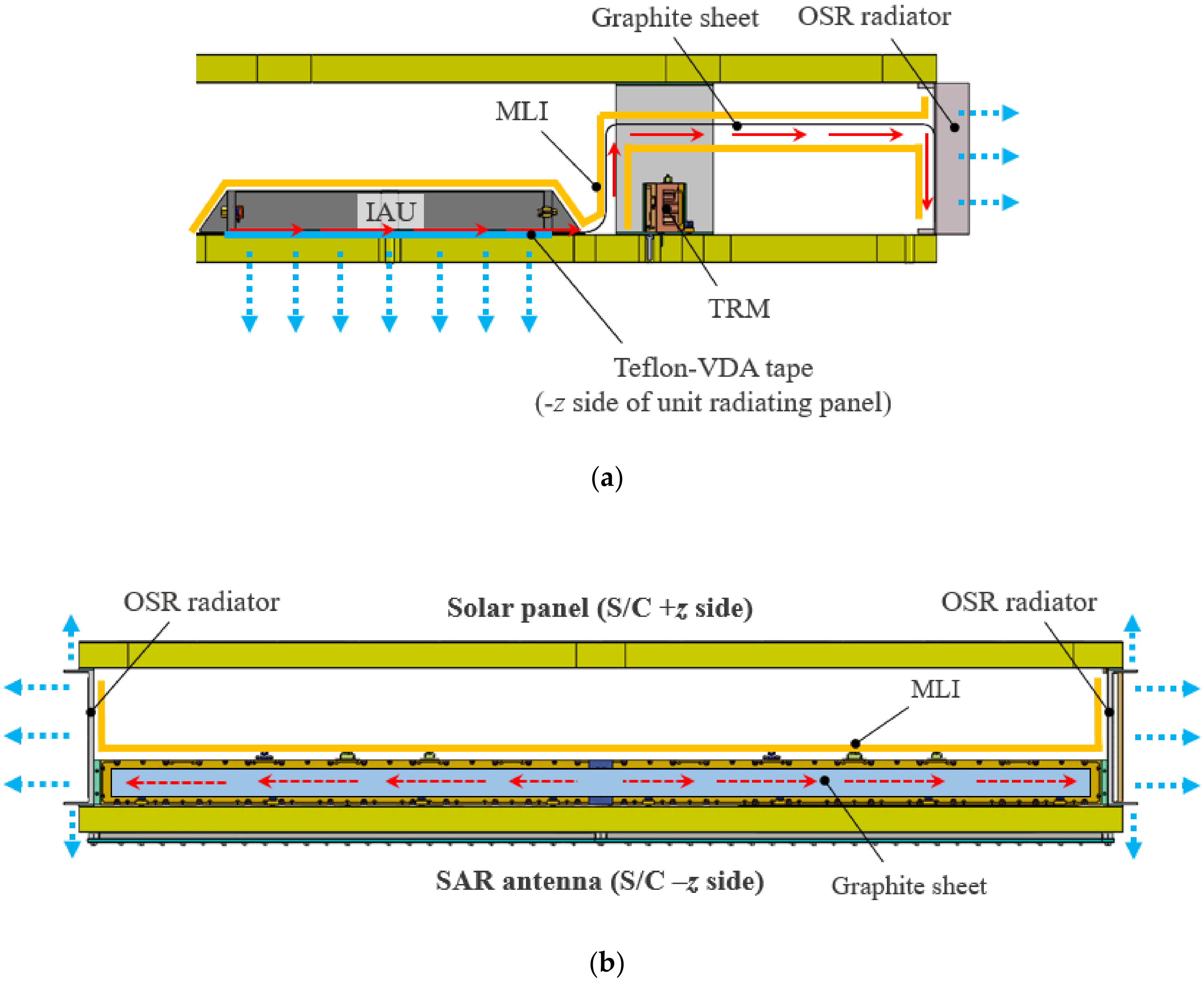
3. New Thermal Design Strategy for S-STEP
4. On-Orbit Thermal Analysis of S-STEP
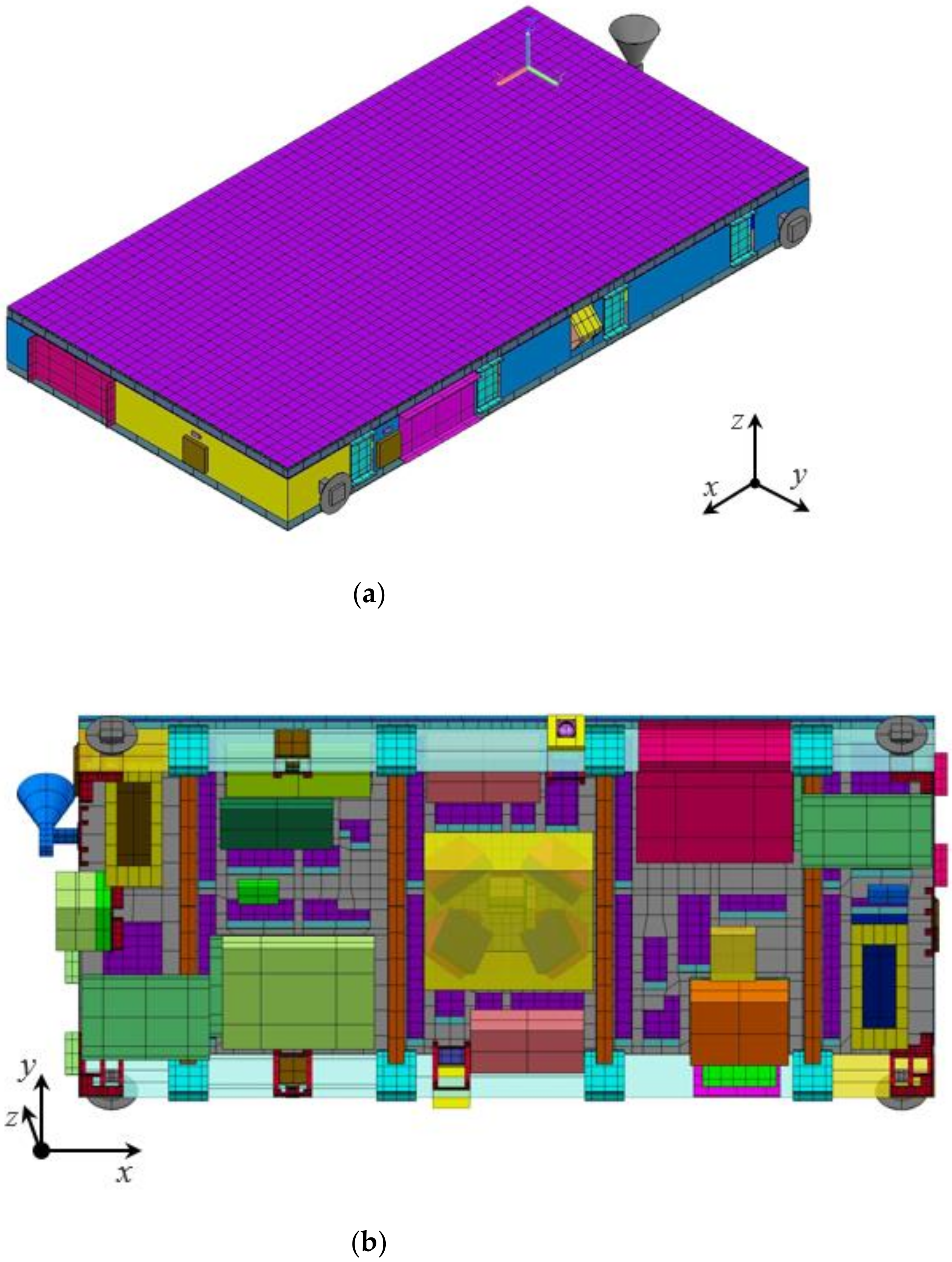
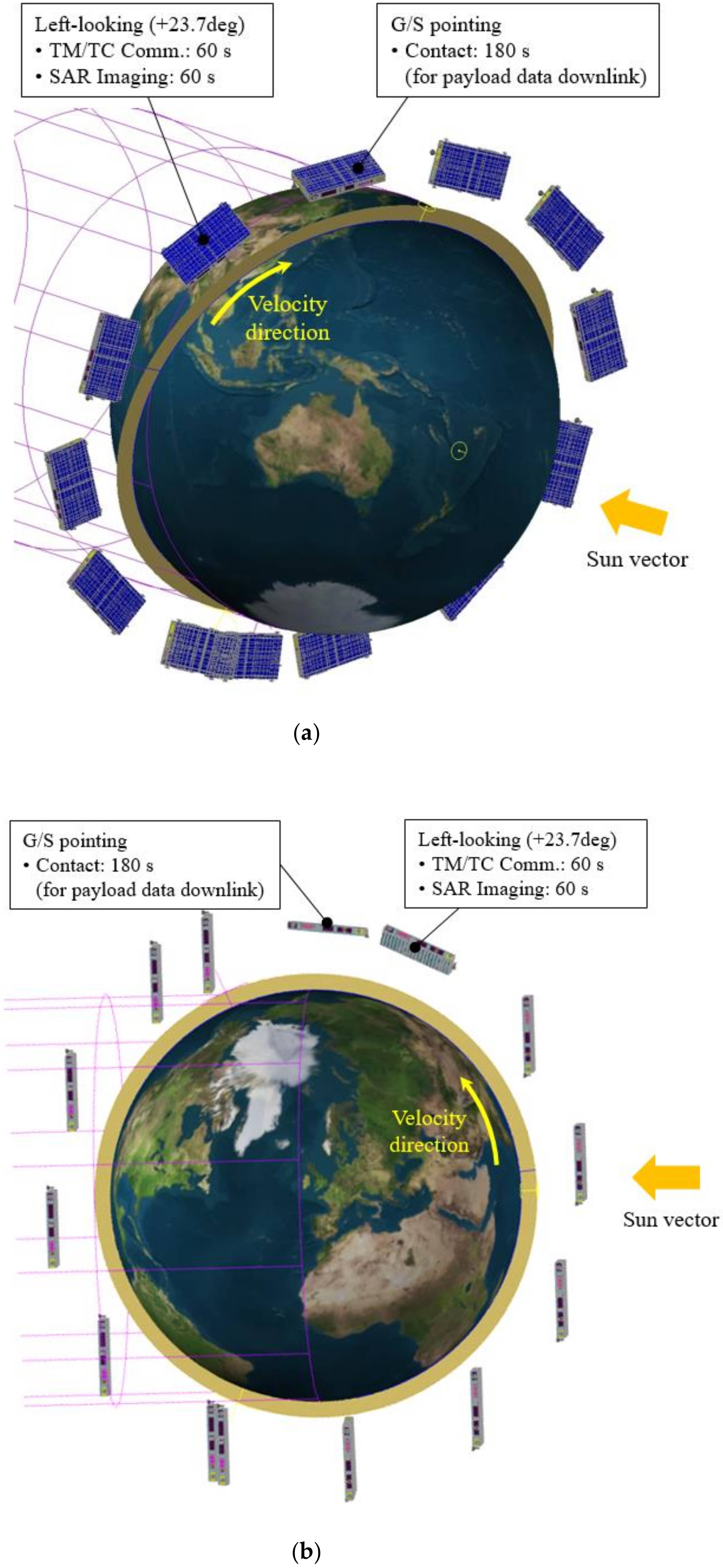
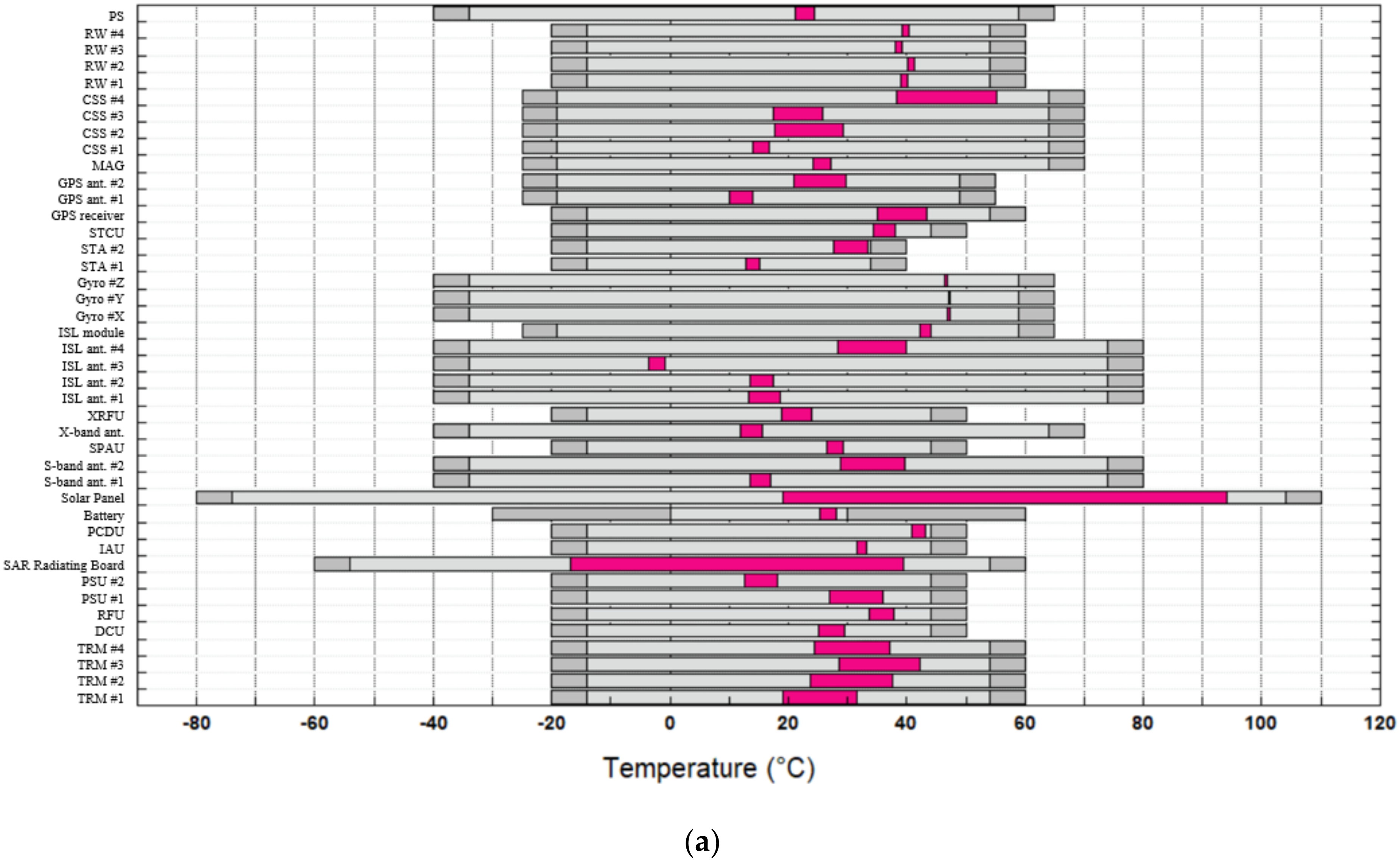
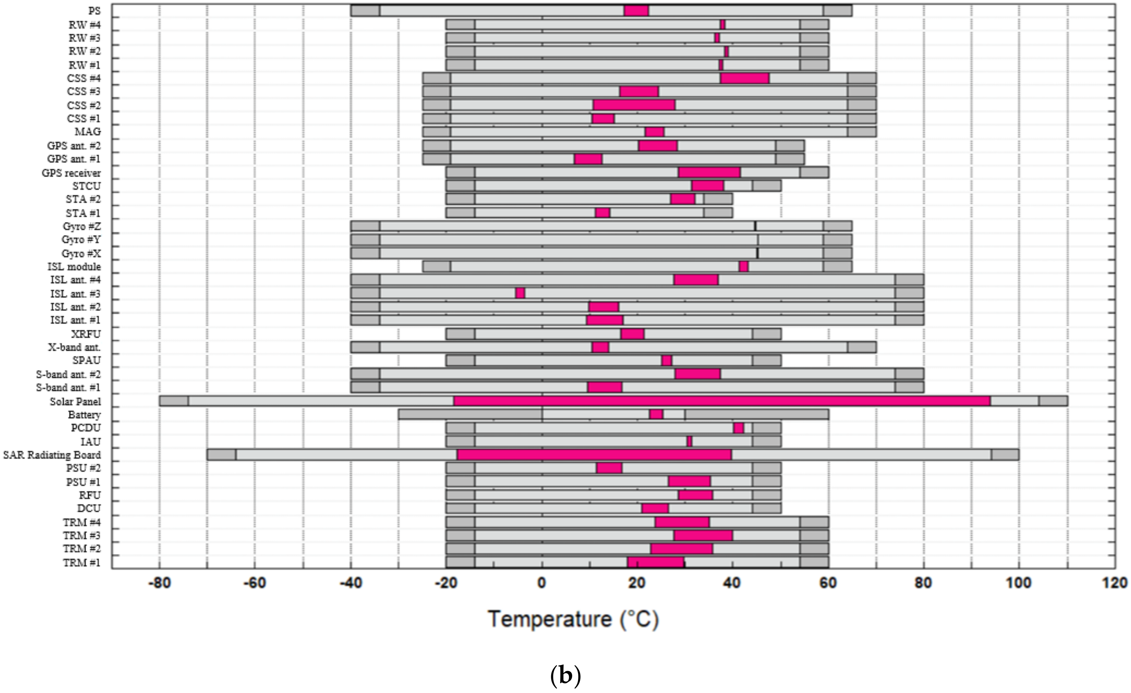
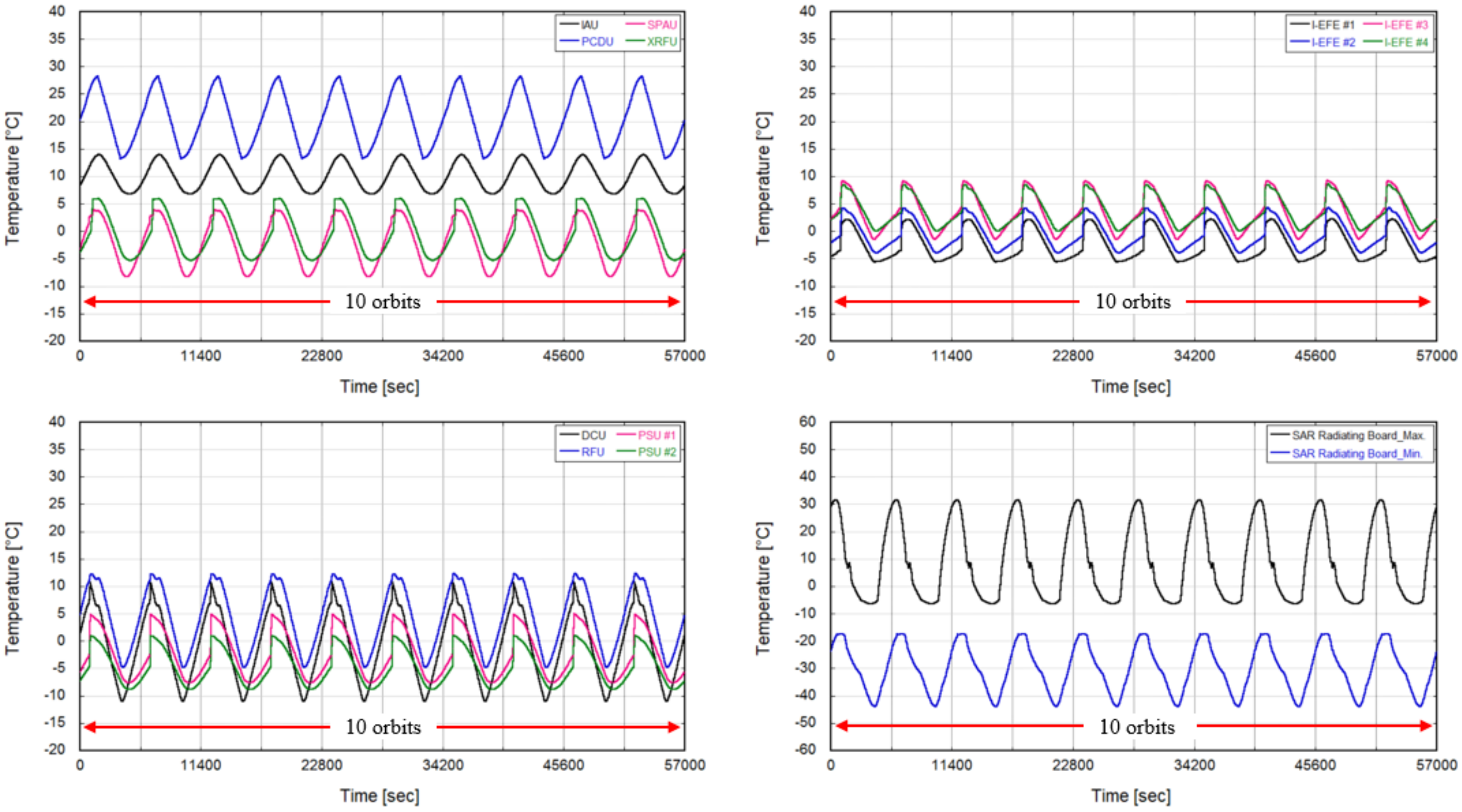
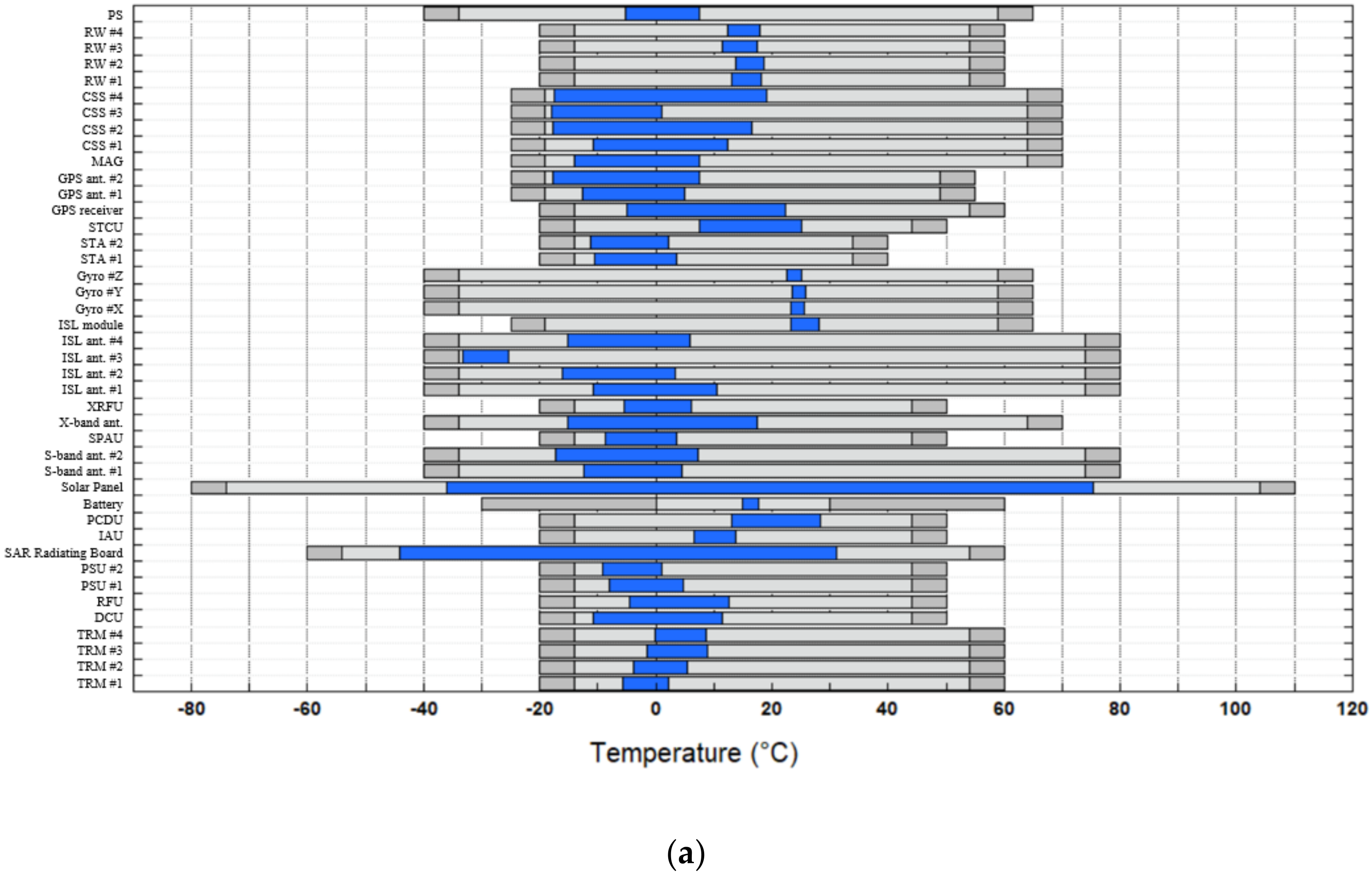
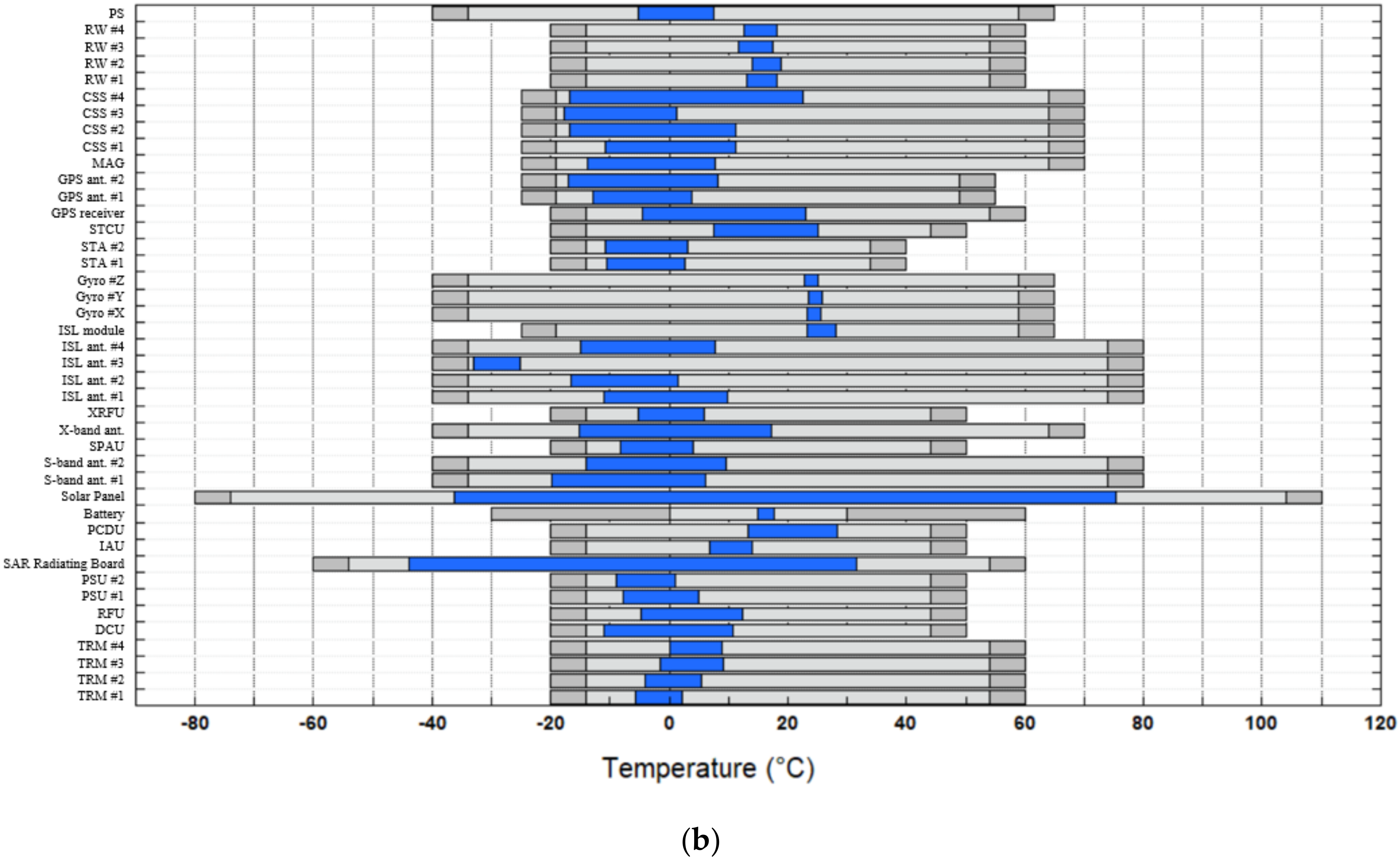
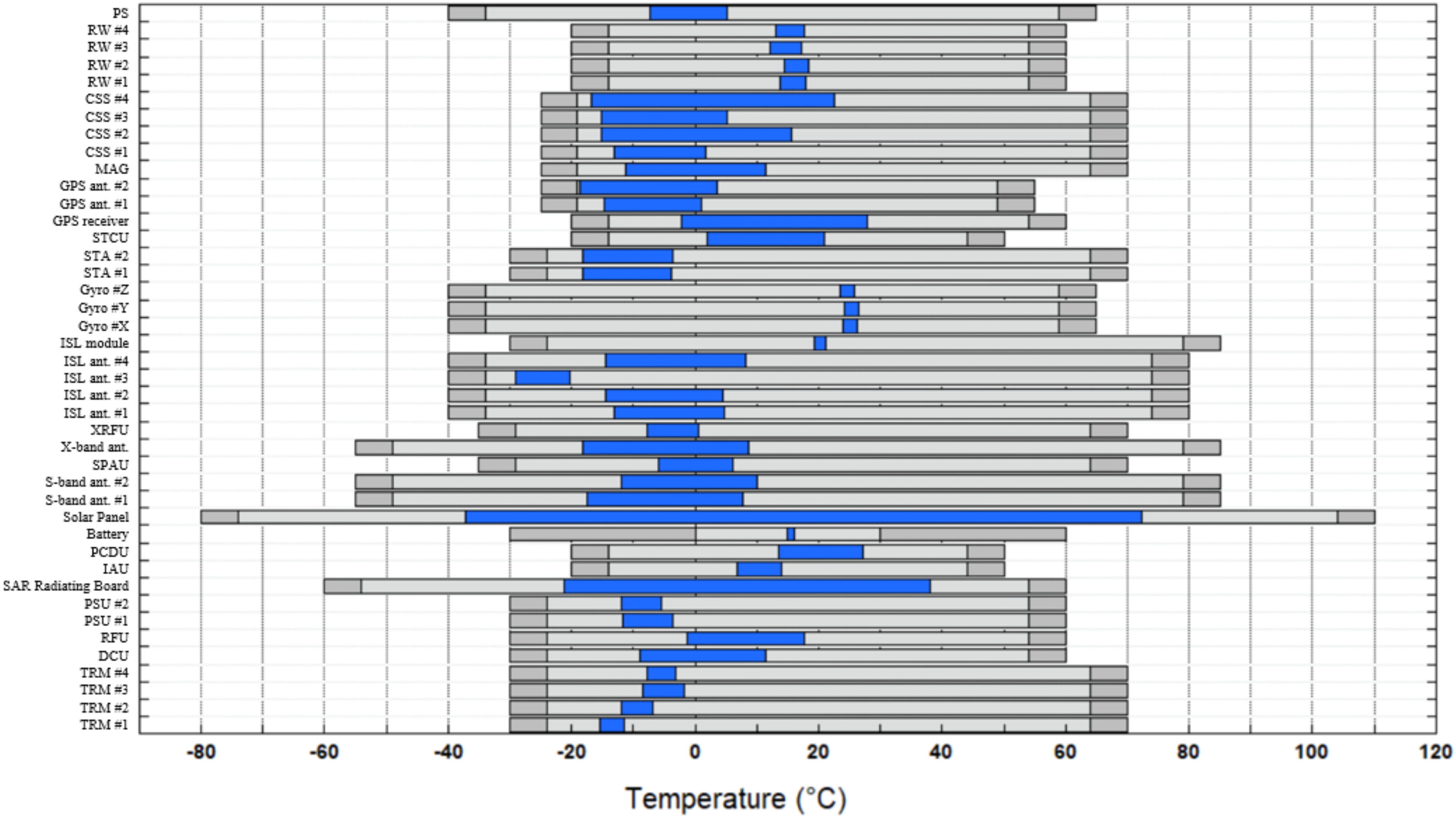
4.1. Overview of Thermal Analysis
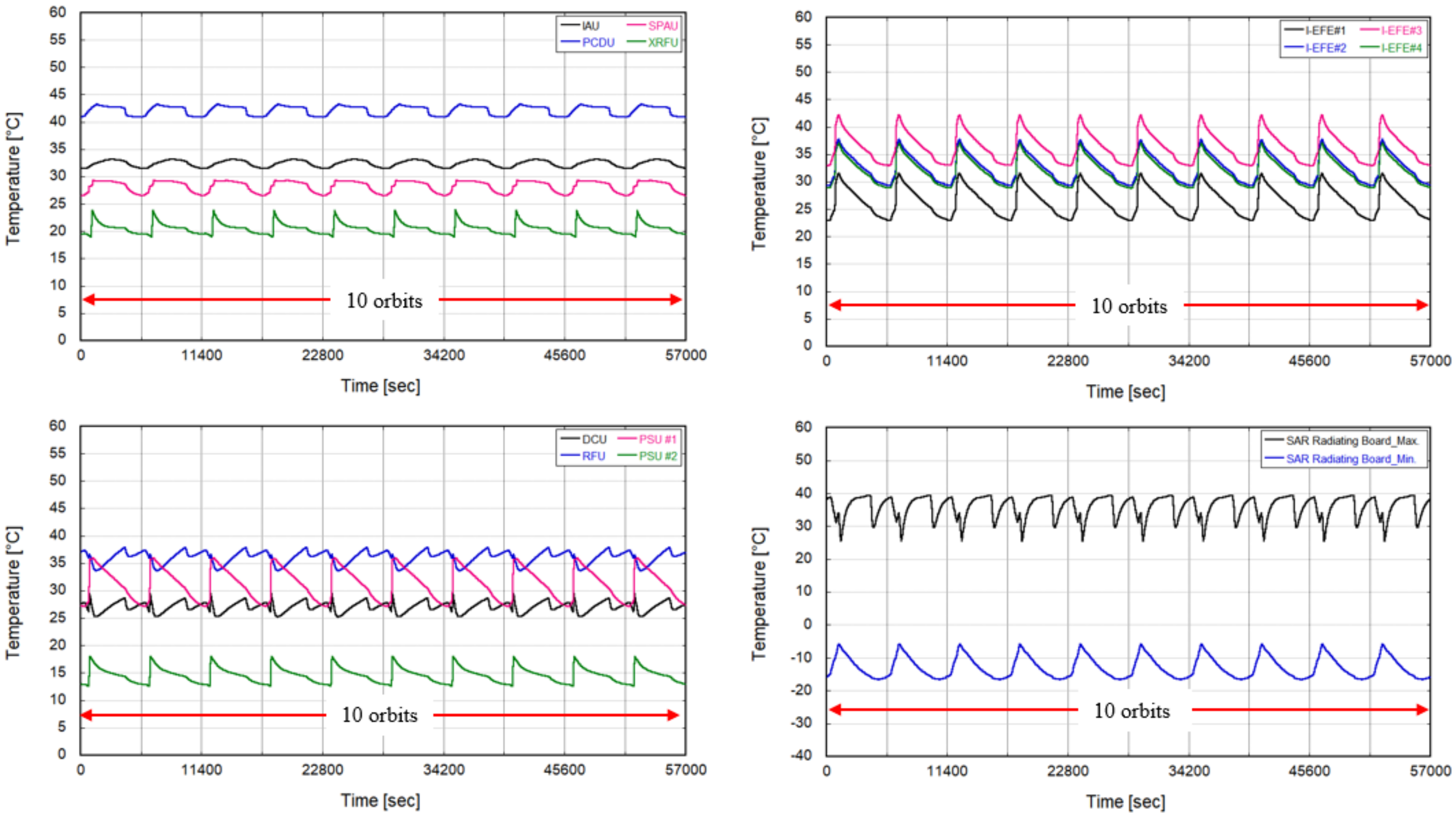
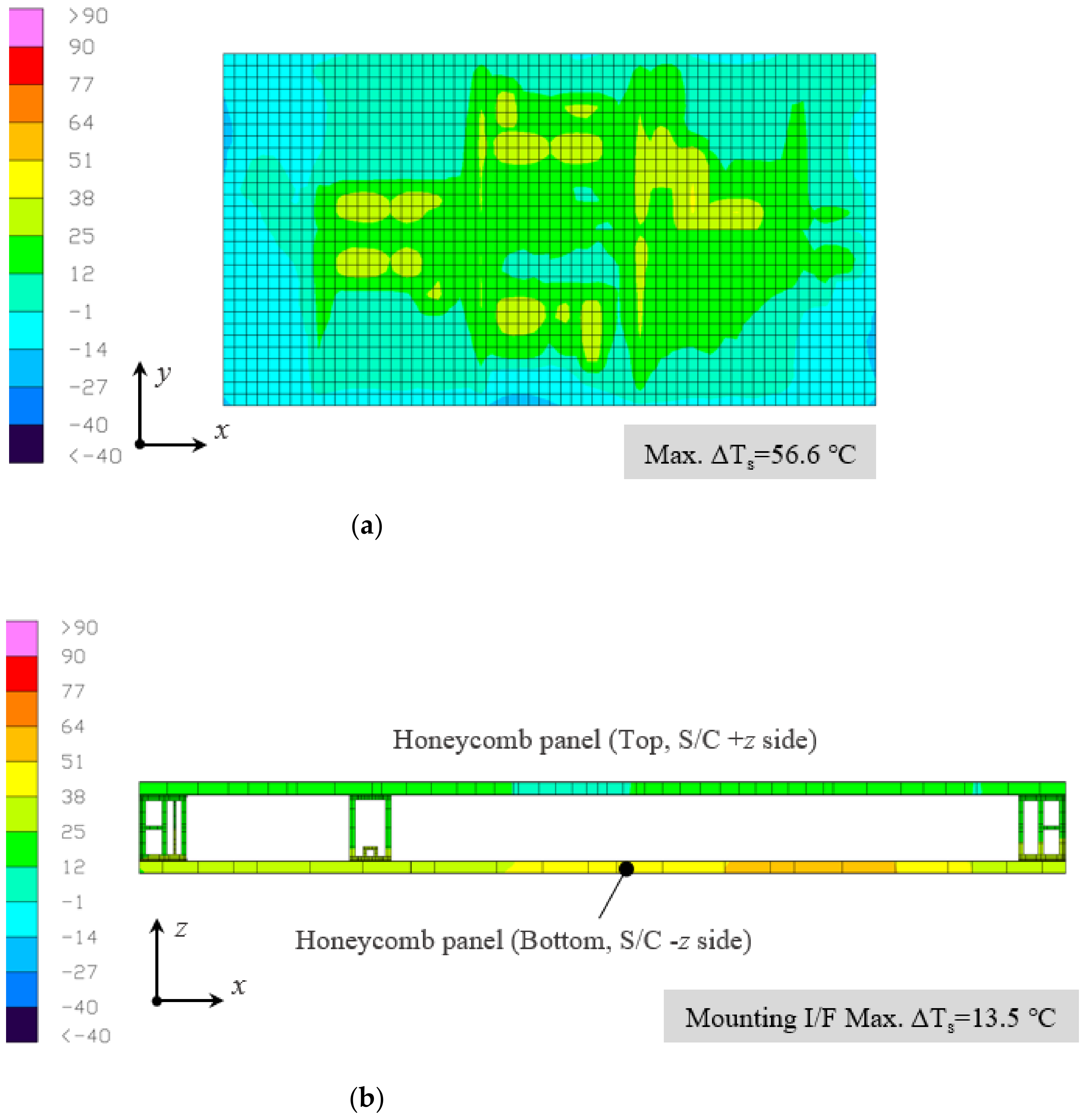
4.2. Results of Thermal Analysis
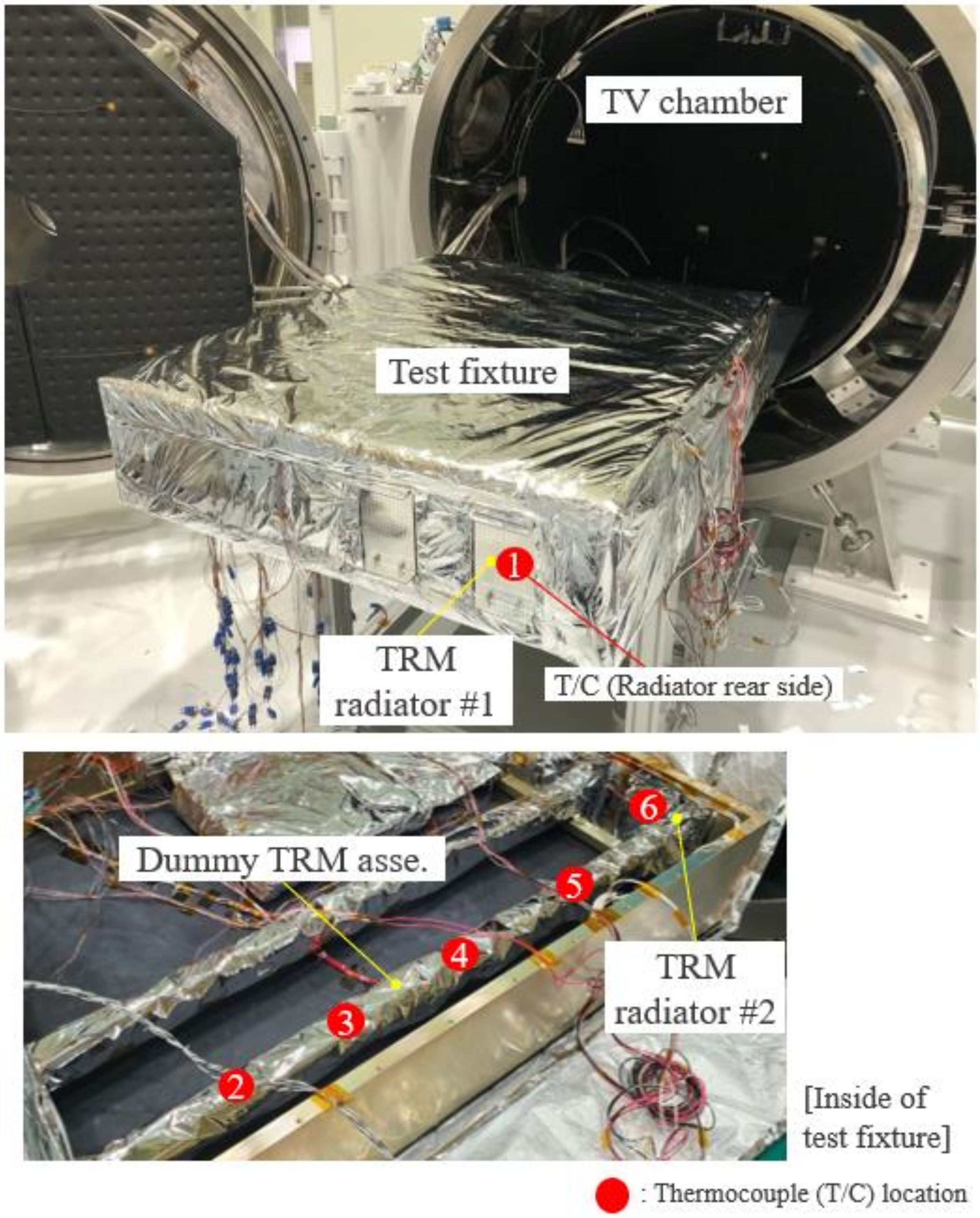
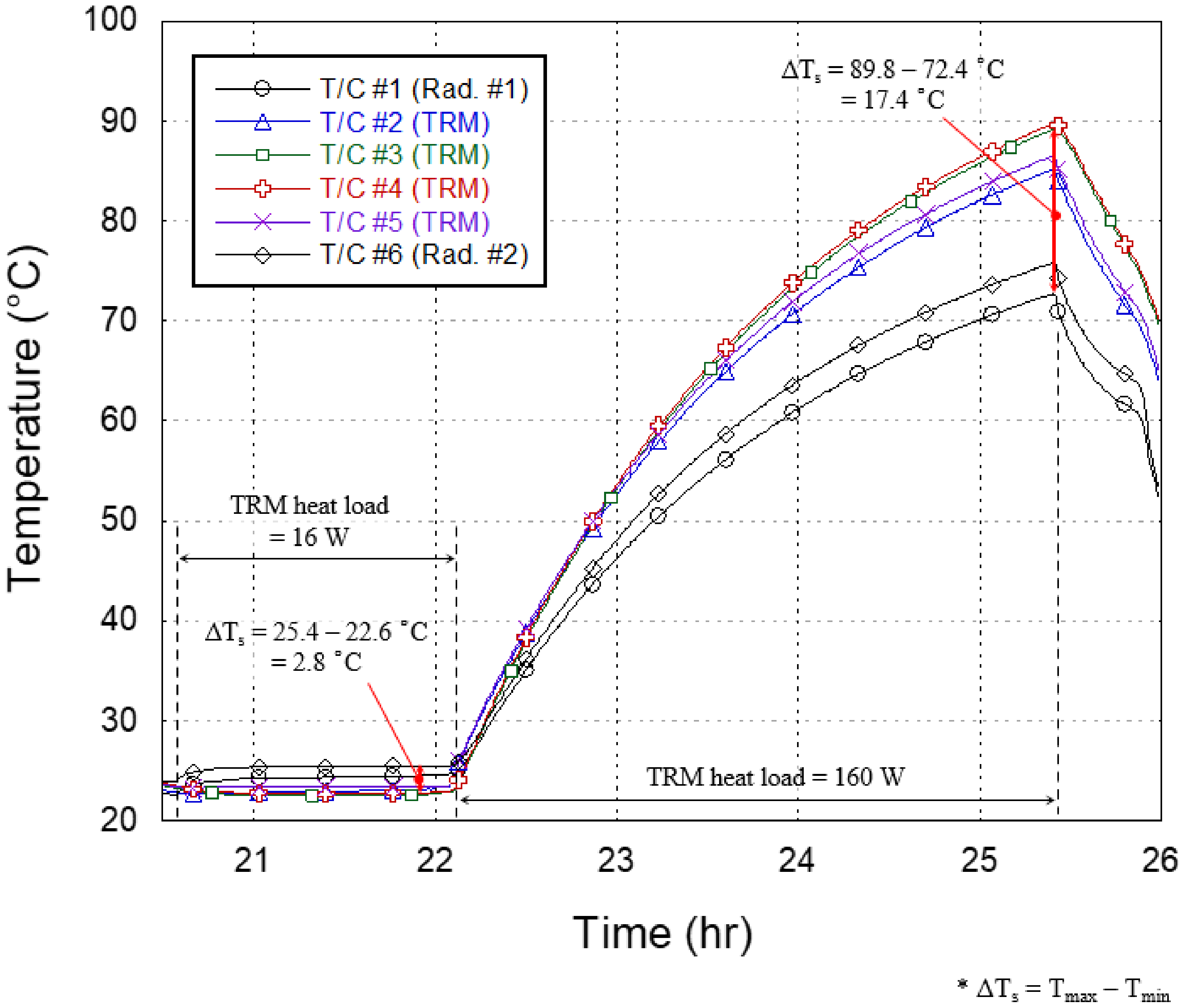
5. Experimental Verification of Key Thermal Design
6. Conclusions
Author Contributions
Funding
Institutional Review Board Statement
Informed Consent Statement
Data Availability Statement
Acknowledgments
Conflicts of Interest
References
- Morgan Stanley. The Space Economy’s Next Giant Leap. 2021. Available online: https://www.morganstanley.com/Themes/global-space-economy (accessed on 1 September 2021).
- Kak, A.; Akyildiz, I.F. Large-Scale Constellation Design for the Internet of Space Things/CubeSats. In Proceedings of the 2019 IEEE Globecom Workshops (GC Wkshps), Waikoloa, HI, USA, 9–13 December 2019. [Google Scholar]
- Planet Labs Inc. Planet. Available online: https://www.planet.com/ (accessed on 1 September 2021).
- Starlink. Available online: https://www.starlink.com/ (accessed on 1 September 2021).
- Project Kuiper. Available online: https://www.amazon.jobs/en/teams/projectkuiper (accessed on 1 September 2021).
- Li, J. Satellite Remote Sensing Technologies; Springer Nature: Cham, Switzerland, 2021. [Google Scholar]
- Paek, S.W.; Balasubramanian, S.; Kim, S.; de Weck, O. Small-satellite synthetic aperture radar for continuous global biospheric monitoring: A review. Remote Sens. 2020, 12, 2546. [Google Scholar] [CrossRef]
- Ignatenko, V. ICEYE Microsatellite SAR Constellation Status Update: Evaluation of first commercial imaging modes. In Proceedings of the IEEE International Geoscience and Remote Sensing Symposium (IGARSS), Waikoloa, HI, USA, 26 September–2 October 2020. [Google Scholar]
- Capella Space. Available online: https://www.capellaspace.com/capella-unveils-worlds-highest-resolution-commercial-sar-imagery/ (accessed on 1 September 2021).
- Synspective. Available online: https://synspective.com/satellite/satellite-strix/ (accessed on 1 September 2021).
- i-QPS. Available online: https://i-qps.net/ (accessed on 1 September 2017).
- Saito, H.; Akbar, P.; Tanaka, K.; Ijichi, K.; Mita, M.; Pyne, B.; Kaneko, T.; Obata, T. Engineering-Model Results of X-band Synthetic Aperture Radar for Small Satellite and Its Application to Constellation Mission. In Proceedings of the 32nd Annual Small Satellite Conference, Logan, UT, USA, 4–9 August 2018; SSC18-VII-01. pp. 1–9. [Google Scholar]
- Perellón, M.; Alvarez, R.; Petrini, P.; Sauer, A.; Dolce, S. Sentinel 1–spacecraft and SAR antenna thermal design, analysis, verification and flight performances. In Proceedings of the 45th International Conference on Environmental Systems (ICES), Bellevue, WA, USA, 12 July 2015. [Google Scholar]
- Cohen, M. NovaSAR-S low cost spaceborne SAR payload design, development and deployment of a new benchmark in spaceborne radar. In Proceedings of the IEEE Radar Conference (RadarConf), Seattle, WA, USA, 8–12 May 2017. [Google Scholar]
- Tan, C.; Yu, Z.; Sun, H.; Shi, G.; Liu, X.; Zhou, Y.; Li, G. Integrated design of X-band phased array antenna with LTCC 3D T/R module. IEICE Electron. Express 2020, 17, 1–6. [Google Scholar] [CrossRef]
- Yang, L.; Li, Q.; Kong, L.; Gu, S.; Zhang, L. Quasi-all-passive thermal control system design and on-orbit validation of Luojia 1-01 satellite. Sensors 2019, 19, 827. [Google Scholar] [CrossRef] [PubMed]
- Yendler, B.; Meginnis, A.; Reif, A. Thermal Management for High Power Cubesats. In Proceedings of the 34th Annual Small Satellite Conference, Logan, UT, USA, 28 July 2020; pp. 1–19. [Google Scholar]
- Ueno, A.; Yamada, K.; Miyata, K.; Nagano, H. Proposal of Functional Thermal Control Systems for High-Power Micro-Satellite and Its Demonstration under Thermal Vacuum Condition. J. Electron. Cool. Therm. Control 2018, 8, 1–17. [Google Scholar] [CrossRef][Green Version]
- Manente, M.; Trezzolani, F.; Magarotto, M.; Fantino, E.; Selmo, A.; Bellomo, N.; Pavarin, D. REGULUS: A propulsion platform to boost small satellite missions. Acta Astronaut. 2019, 157, 241–249. [Google Scholar] [CrossRef]
- AlShehhi, A.; AlMarar, A.; AlShehhi, Y.; AlAmeri, M. Thermal design evaluation of Loop Heat Pipe for small satellite applications using graphene Nano-Particles. In Proceedings of the 70th International Astronautical Congress (IAC), Washington, DC, USA, 21–25 October 2019. [Google Scholar]
- Sharath, B.K.; Joteppa, S.; Dibbi, S.; Chippalkatti, V.; Rajendran, P.; Uma Ravindra, M. Thermal Investigation of Power Supply Module (QDR-PSM) for Space Application Using Numerical and Experimental Approach. In Advances in Small Satellite Technologies; Springer: Singapore, 2020; pp. 493–508. [Google Scholar]
- Kwon, S.C.; Son, J.H.; Song, S.C.; Park, J.H.; Koo, K.R.; Oh, H.U. Innovative Mechanical Design Strategy for Actualizing 80 kg-Class X-Band Active SAR Small Satellite of S-STEP. Aerospace 2021, 8, 149. [Google Scholar] [CrossRef]
- Park, T.Y.; Oh, H.U. New PCB strain-based structural design methodology for reliable and rapid evaluation of spaceborne electronics under random vibration. Int. J. Fatigue 2021, 146, 106147. [Google Scholar] [CrossRef]
- Kaneka Corporation. High Thermal Conductive Graphite Sheet, GraphinityTM 2021. Available online: http://www.elecdiv.kaneka.co.jp/english/graphite/index.html (accessed on 1 September 2021).
- Park, D.; Miyata, K.; Nagano, H. Thermal design and validation of radiation detector for the ChubuSat-2 micro-satellite with high-thermal-conductive graphite sheets. Acta Astronaut. 2017, 136, 387–394. [Google Scholar] [CrossRef]
- C&R Technologies. Thermal Desktop User’s Manual–A Cad Based System for Thermal Analysis and Design; Version 6.1; C&R Technologies: Boulder, CO, USA, 2019. [Google Scholar]
- C&R Technologies. SINDA/FLUINT User’s Manual–General Purpose Thermal/Fluid Network Analyzer; Version 6.1; C&R Technologies: Boulder, CO, USA, 2019. [Google Scholar]
- Adolph, M.; Hackenberg, U.; Reber, R.; Rieger, R.; Schweizer, B.; Adelseck, B.; Brugger, H.; Lorcher, M. High-precision temperature drift compensated T/R-module for satellite based SAR applications. In Proceedings of the IEEE European Microwave Conference, Paris, France, 4–6 October 2005. [Google Scholar]


| Item | Specification | |
|---|---|---|
| Mission lifetime | 3 years | |
| Satellite mass | 80.3 kg | |
| Satellite volume | 1970 mm × 1060 mm × 200 mm | |
| Power | Generation | 340 W (BoL) |
| Storage | 648 Wh | |
| Inter-satellite link | RF (S-band) | |
| TM/TC/Image downlink | S-band/X-band | |
| Attitude pointing accuracy | 0.085° (3σ) | |
| Resolution (@ SAR look angle: 25°) |
| |
| Swath (elevation × azimuth) |
| |
| Image acquisition time (per single pass) |
| |
| Component List | Allowable Temperature Limits [℃] | ||||||
|---|---|---|---|---|---|---|---|
| Operating | Non-Operating | ||||||
| Category | Item | Tmin | Tmax | Tmin | Tmax | ||
| Payload | TRM | #1 | −20 | 60 | −30 | 70 | |
| #2 | −20 | 60 | −30 | 70 | |||
| #3 | −20 | 60 | −30 | 70 | |||
| #4 | −20 | 60 | −30 | 70 | |||
| DCU | −20 | 50 | −30 | 60 | |||
| RFU | −20 | 50 | −30 | 60 | |||
| PSU | #1 | −20 | 50 | −30 | 60 | ||
| #2 | −20 | 50 | −30 | 60 | |||
| SAR antenna (Radiating board) | −60 | 60 | - | - | |||
| Bus | C&DH | IAU | −20 | 50 | −35 | 70 | |
| EPS | PCDU | −20 | 50 | −35 | 70 | ||
| Battery | −30 | 60 | - | - | |||
| Solar panel | −55 | 110 | - | - | |||
| CS | S-band ant. | #1 | −40 | 80 | −55 | 85 | |
| #2 | −40 | 80 | −55 | 85 | |||
| SPAU | −20 | 50 | −35 | 70 | |||
| X-band ant. | −40 | 70 | −55 | 85 | |||
| XRFU | −20 | 50 | −35 | 70 | |||
| ISL ant. | #1 | −40 | 85 | - | - | ||
| #2 | −40 | 85 | - | - | |||
| #3 | −40 | 85 | - | - | |||
| #4 | −40 | 85 | - | - | |||
| ISL module | −25 | 65 | - | - | |||
| ADCS | Gyro | #1 | −40 | 65 | −55 | 85 | |
| #2 | −40 | 65 | −55 | 85 | |||
| #3 | −40 | 65 | −55 | 85 | |||
| STA | #1 | −20 | 40 | −30 | 70 | ||
| #2 | −20 | 40 | −30 | 70 | |||
| STCU | −20 | 50 | −30 | 70 | |||
| GPS Receiver | −20 | 60 | −40 | 85 | |||
| GPS ant. | #1 | −25 | 55 | −30 | 60 | ||
| #2 | −25 | 55 | −30 | 60 | |||
| MAG | −25 | 70 | - | - | |||
| CSS (Coarse Sun Sensor) | #1 | −25 | 70 | - | - | ||
| #2 | −25 | 70 | - | - | |||
| #3 | −25 | 70 | - | - | |||
| #4 | −25 | 70 | - | - | |||
| RW | #1 | −20 | 60 | −30 | 70 | ||
| #2 | −20 | 60 | −30 | 70 | |||
| #3 | −20 | 60 | −30 | 70 | |||
| #4 | −20 | 60 | −30 | 70 | |||
| Propulsion | Thruster | −20 | 40 | −40 | 65 | ||
| Item | Specification |
|---|---|
| Manufacturer | KANEKA Co. |
| Configuration |  |
| Thickness | 40 μm |
| Conductivity |
|
| Density | 2 g/cm3 |
| Flexibility |
|
| Features |
|
| Item | Cold Case | Hot Case |
|---|---|---|
| Altitude (km) | 523.87 | 524.96 |
| RAAN (deg) | 352.34 | 186.03 |
| Eccentricity | 0.00075515 | 0.00075515 |
| Orbit inclination (deg) | 44.2 | 44.2 |
| Date (yyyy.mm.dd hh:mm:ss) | 2024.03.08 07:19:07 | 2025.12.25 00:25:12 |
| Beta angle (deg) | −0.94 | −67.49 |
| Solar constant (W/m2) | 1287 | 1420 |
| Albedo | 0.30 | 0.35 |
| Planetary flux (W/m2) | 227 | 249 |
| Analysis Case | Environmental Condition | Operation Phase | Attitude | SAR Payload Operation | G/S Contact |
|---|---|---|---|---|---|
| 1 | Hot case | SAR imaging | Left-looking | Operation | O |
| 2 | Hot case | SAR imaging | Right-looking | Operation | O |
| 3 | Cold case | SAR imaging | Left-looking | Operation | O |
| 4 | Cold case | SAR imaging | Right-looking | Operation | O |
| 5 | Cold case | Safe-hold | Sun pointing | Non-operation | X |
| Material | Conductivity (W/m/K) | Density (kg/m3) | Specific Heat (J/kg/K) | Remark |
|---|---|---|---|---|
| Al-6061 | 170 | 2768 | 879.2 | Unit, radiator, brackets |
| Al-7075 | 121.2 | 2770 | 961.2 | Honeycomb panel (Facesheet) |
| CFRP | 30 | 1910 | 711.76 | Solar panel |
| Graphite sheet | kX = 1200 kY = 1200 kZ = 5 | 1200 | 1200 | Graphite sheet, 15 layers stacked [25] |
| Honeycomb core | kX = 3.25 kY = 2.17 kZ = 7.71 | 129.75 | 921.6 | Honeycomb panel (Core) |
| Foil radiator | 0 | 300 | 1200 | Foil radiator |
| Kevlar honeycomb | 0.40 | 96 | 1420 | SAR antenna radiating board |
| RF-35A2 | 0.29 | 2280 | 990 | SAR antenna radiating board |
| Sun shield | 1000 | 206 | 1200 | Sun shield |
| MLI | 0 | 300 | 1200 | MLI |
| Material | Absorptivity [α] | Emissivity [ε] | α/ε | Remark |
|---|---|---|---|---|
| Alodine | 0.35 | 0.07 | 5.00 | Radiator, structural brackets |
| Black anodizing | 0.88 | 0.88 | 1.00 | Honeycomb facesheet, battery mounting I/F plate, foil radiator (Inside) |
| Kapton | 0.35 | 0.40 | 0.88 | Honeycomb core (Edge) |
| Gold coating | 0.23 | 0.05 | 4.60 | TRM (SAR ant. side) |
| Graphite sheet | 0.66 | 0.30 | 2.20 | Graphite sheet |
| MLI | 0.05 | 0.05 | 1.00 | MLI, electronic units |
| OSR | 0.11 (BOL) 0.24 (EOL) | 0.80 | 0.14 (BOL) 0.30 (EOL) | Radiator |
| PTFE | 0.12 | 0.85 | 0.14 | SAR antenna (+z-axis) |
| Solar cell | 0.61 | 0.83 | 0.90 | Solar panel |
| Sun shield | 0.46 | 0.14 | 3.29 | Sun shield (Inside) |
| 0.43 (BOL) /0.56 (EOL) | 0.69 | 0.62 (BOL) 0.81 (EOL) | Sun shield (Outside) | |
| Teflon tape | 0.11 (BOL) /0.25 (EOL) | 0.72 | 0.15 (BOL) 0.35 (EOL) | Foil radiator, bottom side of electronic units (+z-axis), solar panel |
| Antenna | 0.25 | 0.75 | 0.33 | GPS ant., ISL ant., S-band ant. |
| VDA | 0.065 | 0.023 | 2.83 | GPS ant., ISL ant., S-band ant. |
| Al-VDA | 0.09 | 0.028 | 3.214 | Honeycomb panel (Local) |
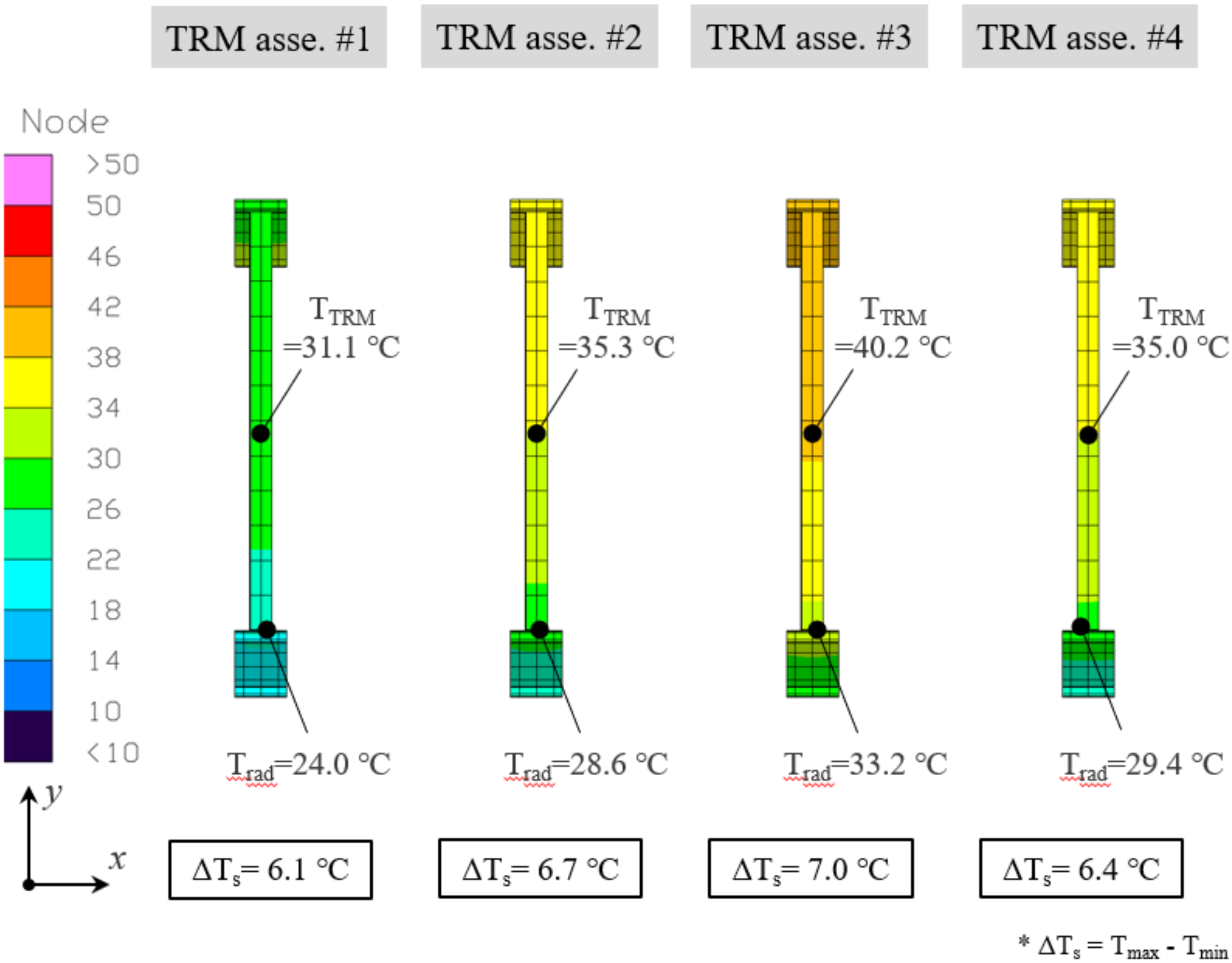
| Orbital Condition | Analysis Case | Operation | Spatial Temperature Diff. (ΔTs) | |||
|---|---|---|---|---|---|---|
| TRM #1 | TRM #2 | TRM #3 | TRM #4 | |||
| Hot case | Case 1 | SAR imaging (Left-looking) | 6.1 | 6.7 | 7.0 | 6.4 |
| Case 2 | SAR imaging (Right-looking) | 6.4 | 7.6 | 7.4 | 6.5 | |
| Cold case | Case 3 | SAR imaging (Left-looking) | 2.7 | 3.8 | 3.1 | 4.0 |
| Case 4 | SAR imaging (Right-looking) | 2.7 | 3.9 | 3.0 | 3.7 | |
Publisher’s Note: MDPI stays neutral with regard to jurisdictional claims in published maps and institutional affiliations. |
© 2021 by the authors. Licensee MDPI, Basel, Switzerland. This article is an open access article distributed under the terms and conditions of the Creative Commons Attribution (CC BY) license (https://creativecommons.org/licenses/by/4.0/).
Share and Cite
Park, T.-Y.; Chae, B.-G.; Kim, H.; Koo, K.-R.; Song, S.-C.; Oh, H.-U. New Thermal Design Strategy to Achieve an 80-kg-Class Lightweight X-Band Active SAR Small Satellite S-STEP. Aerospace 2021, 8, 278. https://doi.org/10.3390/aerospace8100278
Park T-Y, Chae B-G, Kim H, Koo K-R, Song S-C, Oh H-U. New Thermal Design Strategy to Achieve an 80-kg-Class Lightweight X-Band Active SAR Small Satellite S-STEP. Aerospace. 2021; 8(10):278. https://doi.org/10.3390/aerospace8100278
Chicago/Turabian StylePark, Tae-Yong, Bong-Geon Chae, Hongrae Kim, Kyung-Rae Koo, Sung-Chan Song, and Hyun-Ung Oh. 2021. "New Thermal Design Strategy to Achieve an 80-kg-Class Lightweight X-Band Active SAR Small Satellite S-STEP" Aerospace 8, no. 10: 278. https://doi.org/10.3390/aerospace8100278
APA StylePark, T.-Y., Chae, B.-G., Kim, H., Koo, K.-R., Song, S.-C., & Oh, H.-U. (2021). New Thermal Design Strategy to Achieve an 80-kg-Class Lightweight X-Band Active SAR Small Satellite S-STEP. Aerospace, 8(10), 278. https://doi.org/10.3390/aerospace8100278