Article

GA Optimization of Variable Angle Tow Composites in Buckling and Free Vibration Analysis through Layerwise Theory

Department of Mechanical and Aerospace Engineering, Politecnico di Torino, Corso Duca degli Abruzzi 24, 10129 Turin, Italy
Aerospace 2021, 8(12), 376; https://doi.org/10.3390/aerospace8120376
Submission received: 2 November 2021 / Revised: 27 November 2021 / Accepted: 1 December 2021 / Published: 3 December 2021
(This article belongs to the Special Issue Control and Optimization Problems in Aerospace Engineering)

Abstract

:
In the current research, variable angle tow composites are used to improve the buckling and free vibration behavior of a structure. A one-dimensional (1D) Carrera Unified Formulation (CUF) is employed to determine the buckling loads and natural frequencies in Variable Angle Tow (VAT) square plates by taking advantage of the layerwise theory (LW). Subsequently, the Genetic Algorithm (GA) optimization method is applied to maximize the first critical buckling load and first natural frequency using the definition of linear fiber orientation angles. To show the power of the genetic algorithm for the VAT structure, a surrogate model using Response Surface (RS) method was used to demonstrate the convergence of the GA approach. The results showed the cost reduction for optimized VAT performance through GA optimization in combination with the 1D CUF procedure. Additionally, a Latin hypercube sampling (LHS) method with RS was used for buckling analysis. The capability of LHS sampling confirmed that it could be employed for the next stages of research along with GA.

1. Introduction

Fiber-reinforced composites are known as anisotropic materials and are widely used in the engineering field due to their high stiffness and strength-to-weight ratios, which result in lightweight composite structures. Recently, a new class of composite materials was introduced called Variable Angle Tow (VAT) composites (see [1,2,3]). VAT allows the designer to tailor a structure’s desired static and frequency responses under specific loads. In recent years, the use of VAT panels in aerospace applications has increased. The continuous variation of the stiffness properties, obtained by the curvilinear fiber path, provides considerable advantages in comparison with the conventional composite laminates. As the number of design variables increases, the tailoring ability of VAT structures significantly improves for buckling and dynamic properties [4,5,6].
The Classical Laminate Theory (CLT) was originally used for the first investigation of composite laminates. Leissa and Martin [4], for example, employed the Ritz method and thin plate theory to validate a 38 % increase in buckling load and a 21% rise in fundamental frequency, respectively. VAT composite buckling loads improved by 80 % [7]. As a typical finite element model, Tatting and Gürdal [8] used the highly efficient Reighley–Ritz theory. VAT was applied to increase the plate buckling load in Raju et al. [9]. The CLT and the Differential Quadrature Method (DQM) were used to arrive at this solution. A number of studies on the buckling behavior of VAT panels used numerical, semi-analytical, and analytical approaches that largely utilize CLT [10,11,12,13]. Furthermore, CLT was employed by Hachemi et al. and Khaledi et al. [14] for the dynamic study of panels with varying stiffness qualities. For the free vibrations and linear transient analysis of variable stiffness doubly curved shell structures, Sciascia et al. [15] employed an efficient and adaptable Ritz technique. The most frequent numerical method for the comprehensive study of composite structures is the Finite Element Method (FEM). Although this method is precise enough, 3D FEM is tedious and expensive for the design of such structures due to the necessity of a mesh and high processing expenses. It is possible to lower processing costs without sacrificing accuracy by using refined finite element techniques.
Carrera Unified Formulation (CUF) is a general approach that may be used to obtain refined finite element models [16]. Beyond classical theories, there are one-dimensional (beam) and two-dimensional (plate and shell) CUF theories. In Carrera et al.’s [16] book, CUF is presented with condensed notation, expressing the displacement fields over the cross-section in the beam case, as well as the thickness (plate and shell cases), in terms of base functions whose shapes and orders are arbitrary. The displacement field can be on a hierarchical expansion over the cross-section of structures, according to CUF. Within the formulation, different expansion functions, such as polynomial, harmonic, and exponential, can be used. The weak form of governing equations is produced using FEM in this technique. CUF provides an investigation on the desired order for cross-sectional deformation regardless of the problem’s attributes. In comparison to 3D solid finite element models, Carrera et al. [17] introduced 1D CUF models with a considerable reduction in computational cost. In other words, a 1D FEM may be used to analyze complicated 3D structures using CUF. CUF models were used in various fields [18,19,20,21,22] and also in the form of 1D beams [23,24,25,26].
In terms of the recent research work on the improvement of composite plates’ performance on buckling and free vibrations, we would like to further enrich the literature review with works related to the computational analysis and design of composites with different reinforcements. In terms of the improvement of the performance of composite plates on free vibration and buckling analysis, Georgantzinos et al. [27,28] used a computational finite element procedure to evaluate the vibration in graphene composite materials and the buckling behavior of carbon nanotube composite plates under different boundary conditions, in order to show the ability of FEM to be in agreement with experimental tests. Moreover, Uthale et al. [29] carried out a wide-ranging review on the processing of hybrid nanocomposites and finite element modeling to show the recent advances of characterization, simulation, manufacturing, and testing for the high performance of this kind of composite.
Classical theories and the specification of laminate parameters offer a wide range of optimization approaches in composite structures [30,31]. Fukunag and Vanderplaats [32] presented an efficient stiffness approach using lamination parameters as design variables for the orthotropic composites in the classical theory. For instance, Liu et al. [33] used an optimization procedure with the flexural lamination parameters as continuous design variables for 0 , ± 45 , and 90 plies in the composite laminates. Bloomfield et al. [34] expanded their research for a different set of ply orientations in a two-level optimization approach in the buckling problem. They used lamination parameter and plate thickness to minimize the mass in the first level and modified particle swarm to determine the stacking sequences in the laminates. The conventional approach has the advantage of being able to offer appropriate fiber angles for a multiple-ply laminate because the laminate parameters are normally acquired by a set of fiber angles.
Tawfik et al. [35] presented a reliability analysis of the free vibration of composite laminated plates to account for the uncertainty of the material and geometrical properties. They utilized a combination of the second-order reliability method and an artificial neural network to improve the efficiency of their simulation. Furthermore, to avoid time-consuming optimization methods, a surrogate model can be used [36,37]. When the qualities of the constituent materials and the applied loads are uncertain, a robust design optimization algorithm for VAT composite structures can be proposed [38].
GA is the most well-known and frequently used meta-heuristic algorithm, first presented by John Holland in 1975 [39]. GA is a direct search optimization method that, by removing the need for gradient knowledge, might be a useful model for composite problems. In practice, sensitivity is not used to discover structural behavior based on design variables. A detailed analysis of composite structure optimization reveals that algorithm performance predictions can be more difficult with random search issues, and that convergence velocity is slower than a local search with a known starting point [40]. By contrast, better results are produced when potential patterns are followed, and the probability of achieving a global optimum is increased. This feature allows the user to assess the efficiency and computational cost based on their requirements, and it is ideally suited to optimization and reliability challenges. Moreover, Esposito and Gherlone [41] showed the power of the Monte Carlo simulation and Latin hypercube sampling (LHS) to show the robustness of the inverse Finite Element Method, the Modal Method and Ko’s Displacement theory for the inputs’ variability on the reconstruction of the displacement field of a composite wing box.
Previous research [42,43,44] has successfully implemented the CUF technique to perform free vibration analysis of VAT constructions. In this paper, a numerical model based on the CUF and the layerwise theory is presented for the buckling and free vibration analysis of VAT plates subject. A GA was applied to compute the optimal linear fiber angle distribution of different layups for maximum buckling and free vibration under simply supported and clamped boundary conditions. During the optimization phase, all GA sample points were assessed to demonstrate the global optimization via a surrogate model approach: the response surface (RS). Furthermore, the GA results on RS are compared to the RS results from the Latin hypercube sampling method to demonstrate LHS’s capacity to acquire a precise domain of optimal results.

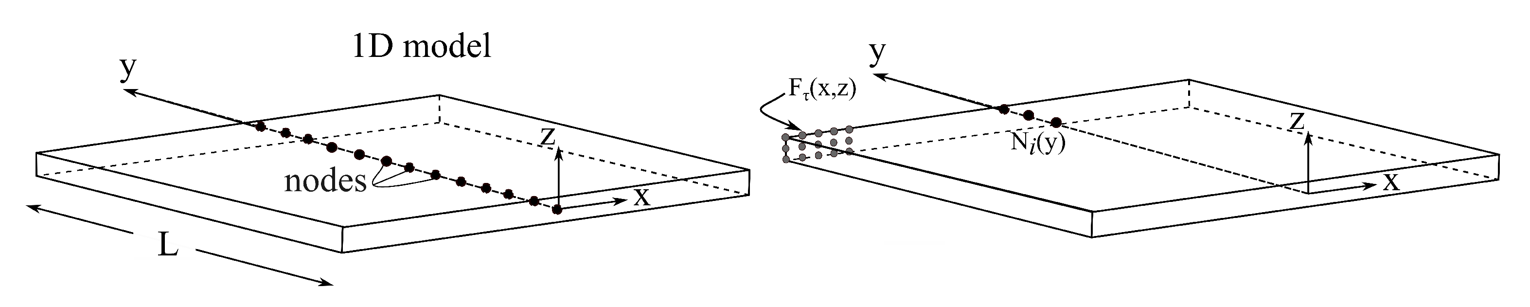
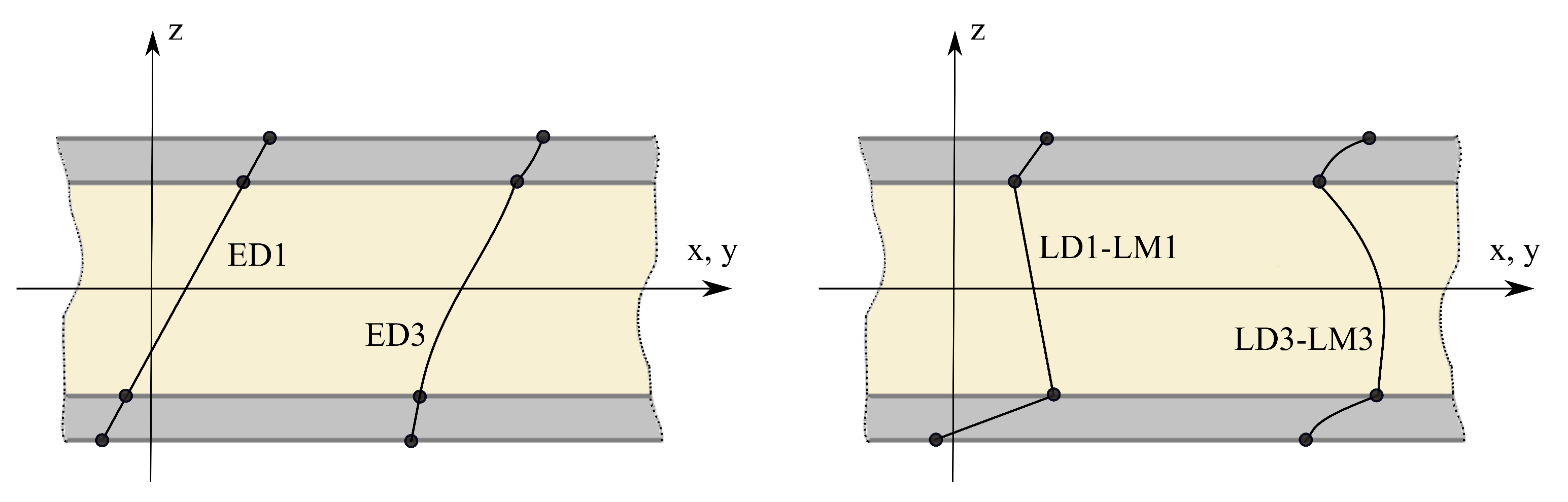
2. Carrera Unified Formulation for Beams

Preliminaries

In the CUF framework, the cross-section of the beam is considered to be located on the x–z-axis of a generic Cartesian reference system, as shown in Figure 1. Beam boundaries along the y-axis can be defined in the range 0 y L , where L is the length of the beam, see Figure 1. We next introduce the displacement vector
u ( x , y , z ) = { u x , u y , u z } T
as well as the stress, σ , and strain, ϵ :
σ = { σ x x , σ y y , σ z z , σ x z , σ y z , σ x y } T
ϵ = { ϵ x x , ϵ y y , ϵ z z , ϵ x z , ϵ y z , ϵ x y } T
In composite materials, independently of the fiber orientation angle, the three-dimensional behavior of a ply of composite made out of linear elastic material can be written in the form of Hooke’s law:
σ = C ϵ
where C stands for the material matrix of the elastic coefficients. The displacement field for the beam structure in CUF can be expressed as the generic expansion of primary unknowns:
u ( x , y , z ) = F τ ( x , z ) u τ ( y ) , τ = 1 , 2 , , M
where F τ is the expansion function of the cross-section over the x–z-plane, u τ is a generalized displacement vector, M represents the expansion term, and the repeated subscript τ stands for summation. The kinematics of the model can be modified according to the function F τ as a class of a 1D CUF beam model.
In this work, Lagrange polynomials are used as expansion functions and are denoted as L 9 . In particular, the nine-node Lagrange element (L9) is adopted, and it ensures a quadratic interpolation over its domain Lagrange polynomial expansions can formulate the quadratic higher-order kinematics. The L9 polynomial expansion is defined as the following kinematics proposed by [16,45,46]:
u x ( x , y , z ) = F 1 ( x , z ) u x 1 ( y ) + F 2 ( x , z ) u x 2 ( y ) + . . . + F 9 ( x , z ) u x 9 ( y ) u y ( x , y , z ) = F 1 ( x , z ) u y 1 ( y ) + F 2 ( x , z ) u y 2 ( y ) + . . . + F 9 ( x , z ) u y 9 ( y ) u z ( x , y , z ) = F 1 ( x , z ) u z 1 ( y ) + F 2 ( x , z ) u z 2 ( y ) + . . . + F 9 ( x , z ) u z 9 ( y )
where F 1 , F 2 , . . . , F 9 are the nine Lagrange polynomials on the cross-section coordinates, and u x 1 , u y 1 , u z 1 , . . . , u z 9 are 27 unknown displacement variables of the y coordinate that represent pure displacement components at each point of the L 9 polynomial domain. The Lagrangian expansion allows the laminate to be evaluated in the LW approach design, which is considered by determining a specific model for each layer. As a result, the description of the cross-sectional area is specified separately on the laminate sheet and each layer. LW increases the accuracy of mechanical behavior differentiation, unlike the classical ESL-based model [47]. In this way, the actual description of the laminates can be achieved, as shown in Figure 2.
In addition, the combination of the FEM and the CUF theory of structure approximations leads to:
u ( x , y , z ) = F τ ( x , z ) N i ( y ) q τ i i = 1 , 2 , K
where N i stands for the shape function and i is the index for the number of nodes on the beam element; q τ i is the vector of the FE nodal parameters and K is the number of nodes in the element.
Based on the Principal of Virtual Displacement (PVD), the virtual internal work can be written as follows:
δ L i n t = V δ ϵ T σ d V
where L i n t stands for the strain energy, V is the volume of the element, σ is the stress vector, and δ ϵ is the virtual variation of strain, which is presented as:
δ ϵ = b δ u = b ( F s ( x , z ) N j ( y ) ) δ q s j
where b is a differential operator of the strain–displacement relations; j and s represent the shape function and expansion function indices, respectively; F s are expansion functions over the x–z coordinates of the cross-section; N j stands for the j-th shape function; and δ q s j is the virtual variation of nodal unknowns. Equation (9) can then be written as follows:
δ L i n t = δ q s j T V b T N j ( y ) F s ( x , z ) C b F τ ( x , z ) N i ( y ) d V Fundamental Nucleus q τ i = δ q s j T k τ s i j q τ i
where k τ s i j is the CUF Fundamental Nucleus (FN) of the matrix k . The FN is a 3 × 3 matrix that represents the basic building block that can be expanded by using the indices to obtain the element stiffness matrix of any arbitrary refined beam model [45].
Depending on the path function in VAT composites, each layer offers point-by-point continuous angle variations with different values. In the case of VAT, FN components use volume integrals. For the sake of brevity, only two terms of the FN are given below; others can be achieved through permutations [16]:
k x x τ s i j = V C 22 F τ , x F s , x N i N j d V + V C 66 F τ , z F s , z N i N j d V + V C 44 F τ F s N i , y N j , y d V ; k x y τ s i j = V C 23 F τ F s , x N i , y N j d V + V C 44 F τ , x F s N i N j , y d V
In this case, the stiffness coefficients C of the elastic stiffness tensor can vary within the computational domain. Therefore, they must remain in the FN integral. In the VAT structure, each fiber path can be defined as an arbitrary function, and the fibers follow a curvilinear pattern. Hence, in the plate domain, C is no longer constant. Thus, integrals can be introduced in a unique form from a volume based on Equation (11). For VAT composites in the buckling problem, the Tangent stiffness matrix is presented in terms of CUF and FEM approximations [16]. In this case, the stable buckling problems can be written in linearized form as virtual variation of the internal strain energy δ ( δ L i n t ) :
δ ( δ L i n t ) δ q τ i T k τ s i j δ q s j + δ q τ i T k σ 0 τ s i j δ q s j = δ q τ i T ( k τ s i j + k σ 0 τ s i j ) δ q s j
where δ ( δ L i n t ) is the sum of linear stiffness and the virtual variation of work, which is associated with the initial stress of σ 0 . Then, using Equations (5), (7), and (12), and Green–Lagrange nonlinear strain-displacement relations, the following formulas can be obtained as in Equation (13) (see [45,48]), where k σ 0 τ s i j appears in the diagonal matrix form as the FN of the geometrical stiffness matrix, which is expressed for the buckling as:
k σ 0 τ s i j = ( V σ x x 0 F τ , x F s , x N i N j d V + V σ y y 0 F τ F s N i , y N j , x d V + V σ z z 0 F τ , z F s , z N i N j d V + V σ x y 0 F τ , x F s N i N j , y d V + V σ x y 0 F τ F s , x N i , y N j d V + V σ x z 0 F τ , x F s , z N i N j d V + V σ x z 0 F τ , z F s , x N i N j d V + V σ y z 0 F τ , z F s N i N j , y d V + V σ y z 0 F τ F s , z N i , y N j d V ) I
where the stress tensor is obtained by nine components related to 3 × 3 as an identity matrix I . Finally, global matrices are assembled in classical FEM. The critical buckling loads are determined as those initial stress states σ 0 that make the tangent stiffness matrix singular; i.e., K + K σ 0 = 0 (refer to [45]).
For free vibration in the framework of the 1D CUF beam model, the same approach can be written based on Equations (7)–(10). After that, the work done by the inertial forces provides the fundamental nucleus of the mass matrix [45]. The virtual variation of the internal work can be written as follows:
δ L i n e = V ρ u ¨ δ u T d V
where ρ stands for the material density and u ¨ is the acceleration vector.

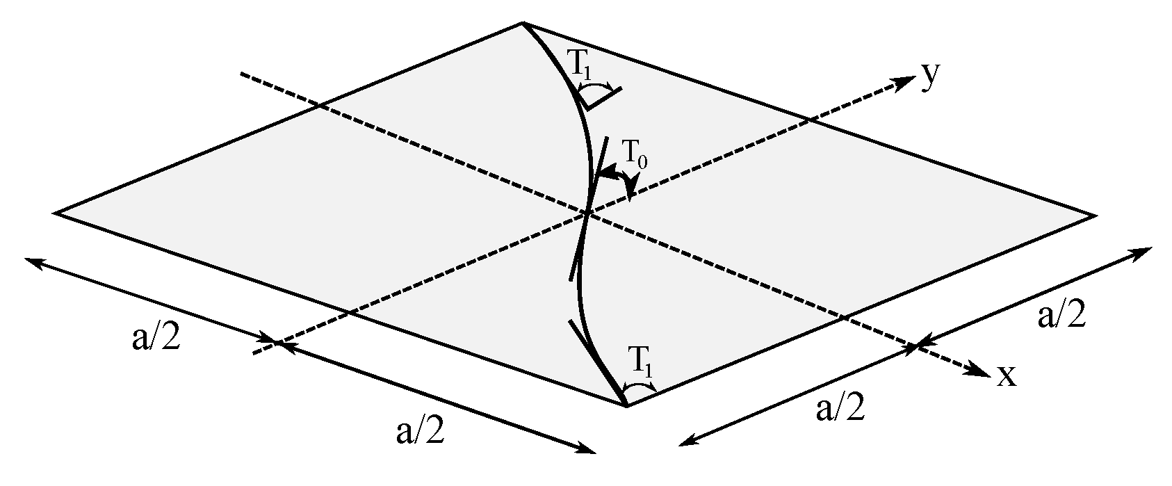
3. Constitutive Equations for VAT Laminates

The analysis of composite structures needs an accurate description of the laminate level. In the current study, this aim is satisfied by layerwise capabilities ensured by LE models, which provide an independent kinematic description for each layer of the laminate. Depending on the dimension of the composite and applied loads, usually the results obtained by layerwise models are more accurate than those obtained with an equivalent single layer where a unique expansion is used for all layers in the composite structure. With the CUF approach, a suitable cross-section description can be used to describe the layers of the laminate separately. This procedure makes it suitable for the analysis of new materials such as VAT laminate. The fiber angle in VAT composites is a spatial variable where the matrix C is no longer constant in each ply, while it is a function of the coordinates of the point that is considered (see Equation (11)). The first analysis concerns a 254 × 254 mm square laminate with a thickness of 0.15 mm for each ply, designed in a balanced symmetrical 16-layer square plate. The mechanical properties of the material are given in Table 1.
The linear variation of the fiber orientation angle has shown a suitable change in the design, analysis, and manufacture construction of VAT composites [1,7,10,49]. As shown in Figure 3, the fiber path can be designed for a curvilinear fiber path that linearly varies along an axis, which in the current paper is along the beam axis y on the plane and can be set as follows [3,50]:
θ ( y ) = 2 ( T 1 T 0 ) | y | a + T 0
where T 0 is the fiber orientation angle in the center of the plate, where x = 0 , and T 1 is the fiber orientation angle at the edges, x = ± a 2 . a is the width of the VAT panel. The fiber orientation angle varies along the y-axis for manufacturing the entire ply; see Figure 3. In this study, the fiber angle orientations are designed with [ < T 0 | T 1 > < T 0 | T 1 > / < T 0 | T 1 > < T 0 | T 1 > ] s based on the reference study (see [44,51]).
Note that the present study uses an equal number of functions through both orthogonal directions x and y for all cases.

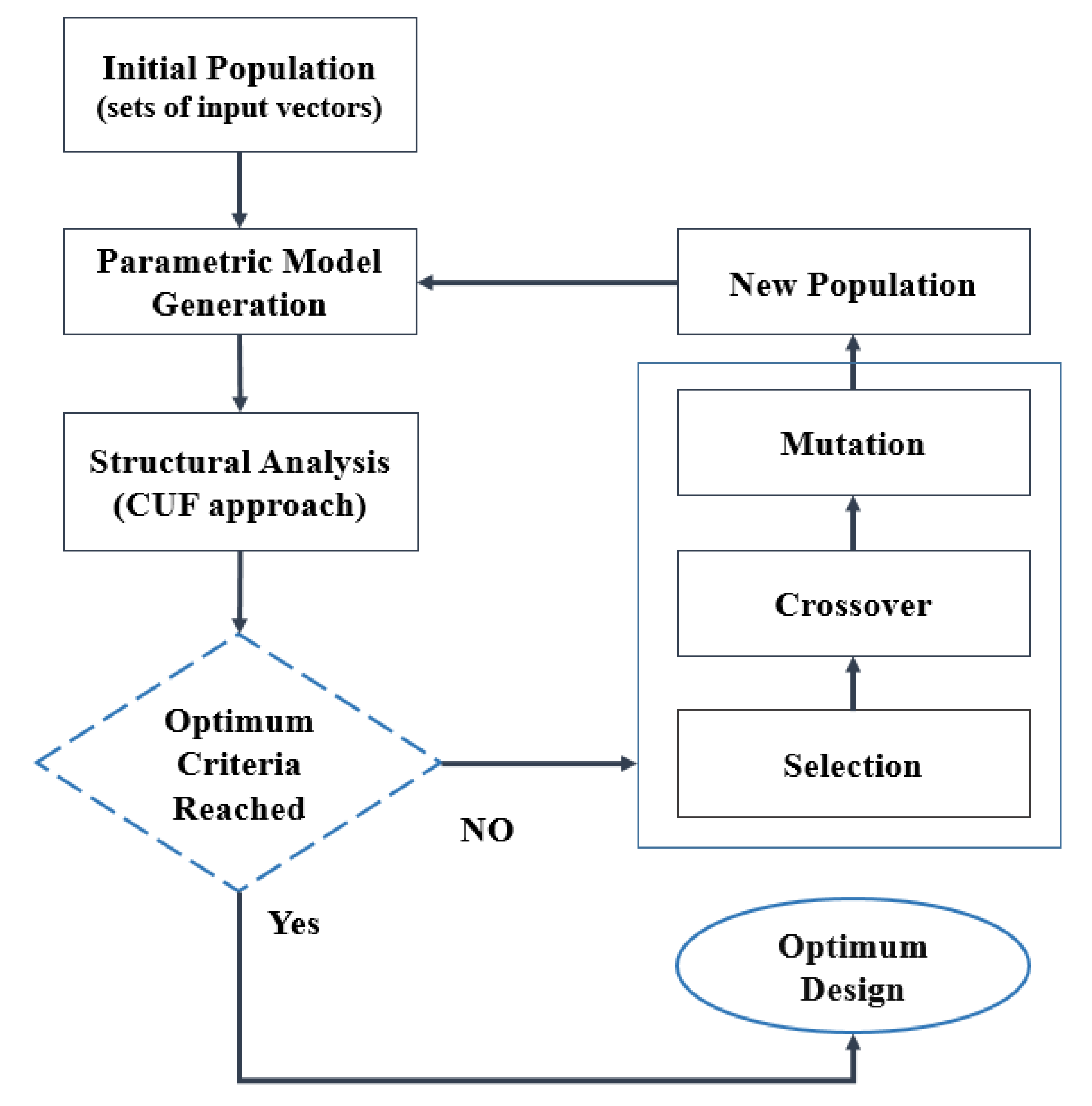
4. Optimization for VAT Composite Studies

4.1. Direct Search Stochastic Methods

Recently, many optimization methods have been used to optimize engineering structures. GA, as one of the meta-heuristic evolutionary algorithms, can be employed to solve many optimization problems. GA is frequently employed to find the optimal solution or near-optimal solution for difficult problems. Despite most of the optimization algorithms requiring having the exact solution for the objective function and respective design variables, the objective function value of the GA is enough to arrive at the optimal solution. GA is initialized with several starting points and can consequently search in several different directions of the searching domain of the problem. Therefore, GA is known as a large search space and is suitable for complicated problems. In GA, the first fitness function is defined, which the final optimization aims to minimize. Random changes are created in the GA, examined for the solution, and compared with the fitness function for evaluation of the required changes. GA is a population model that is generated stochastically. Then, the fitness is evaluated and scored by the fitness function value. After that, the new generation is created by providing the crossover/mutation operations on the eligible individuals, which are chosen from the previous generation. Parents are chosen from the population of these individuals. In this case, the parents who have a better fitness value can create the children for the next generation [52]. Therefore, during the progressive step condition, the fitness function shows an improvement.

4.2. Surrogate Model: Response Surface

The response surface is a surrogate model which is a powerful approach for analyzing the systems. RS is a very effective technique to map the functional behavior in a system relative to parameter values and behavioral variability. In this method, a set of parameter values was defined which were used to map the response of the system [53]. In this study, GA outcomes are mapped in the form of RS for both buckling and free vibration analyses.

4.3. Modeling of VAT Composite in Buckling Analysis

In the case of evaluation of the critical buckling load, the boundary condition (BC) is set to be simply supported (SSSS, Figure 4). The compression load F = 1   kN is applied to the end edges of the plate along the y-direction, as shown in Figure 4.
The VAT plate is introduced by two design variables, T 0 and T 1 . The current goal is to find the optimal fiber path with a maximum buckling load of F c r . The problem of the maximum buckling load is defined by the limitation of the constraints of the design variables, see [54,55,56]:
Minimize : 1 F c r , subject to : 0 T 0 , T 1 90
where 1 / F c r stands for the objective function as the first critical buckling load. For VAT properties, the entire structural set is done within the CUF framework as a numerical model. The current CUF approach provides continuous and smooth fiber orientation angles with a smaller number of elements (Fallahi et al. [44]) than the model built in ABAQUS by Hao et al. [51].

4.4. Modeling of VAT Composite in Free Vibration Analysis

The boundary conditions are set on the fully clamped edges (CCCC) for the natural frequency problem. Additionally, two different design variables, T 0 and T 1 , are considered as design variables. The aim is to obtain the optimal fiber path in which the first natural frequency f 1 is maximal. The optimization problem can be followed:
Minimize : 1 f 1 , subject to : 0 T 0 , T 1 90
where 1 / f 1 is the objective function and T 0 and T 1 are design variables within a certain range of constraints.
The GA optimization in the MATLAB R 2017 b environment was linked to the 1D CUF VAT model in Fortran to solve both problems, as shown in Figure 5.
The GA was continuously solved until the convergence requirement was satisfied. To define symmetric and balanced laminates for buckling and free vibration assessments, quasi-isotropic (QI) laminates having 0 , ± 45 , and 90 plies were utilized as a baseline. In addition, two constant stiffness (CS) laminates with [ ± 45 ] and [ 0 ] 16 T layups were determined for the VAT laminate reference design [44,51] which is named in the current paper as V A T 1 , (see Table 2) and will be compared with the current study’s results.

5. Optimization Results and Discussion

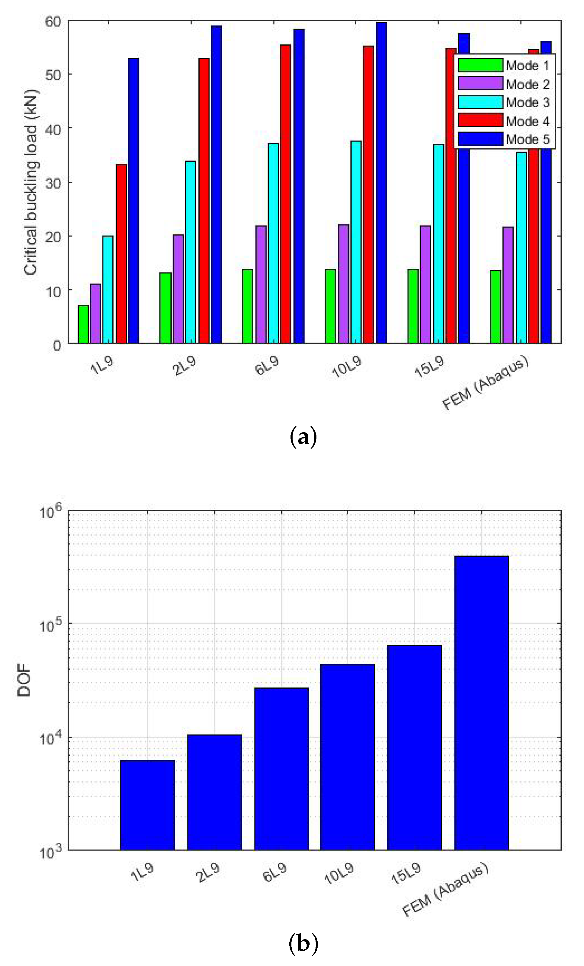
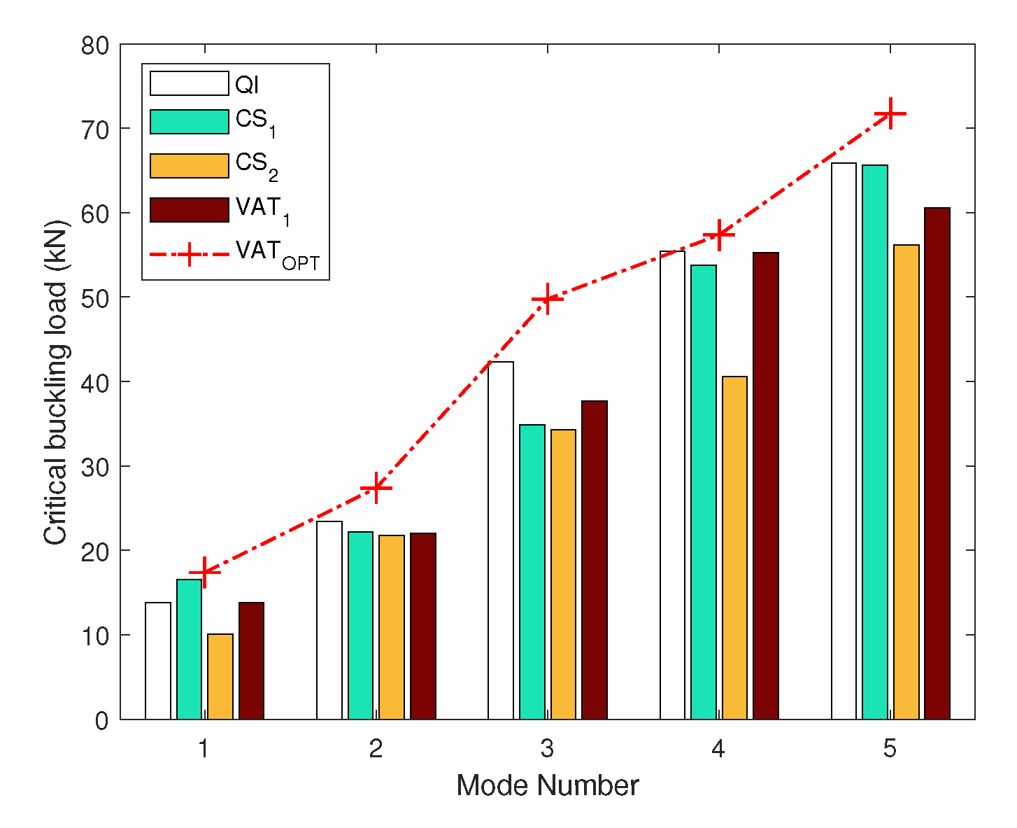
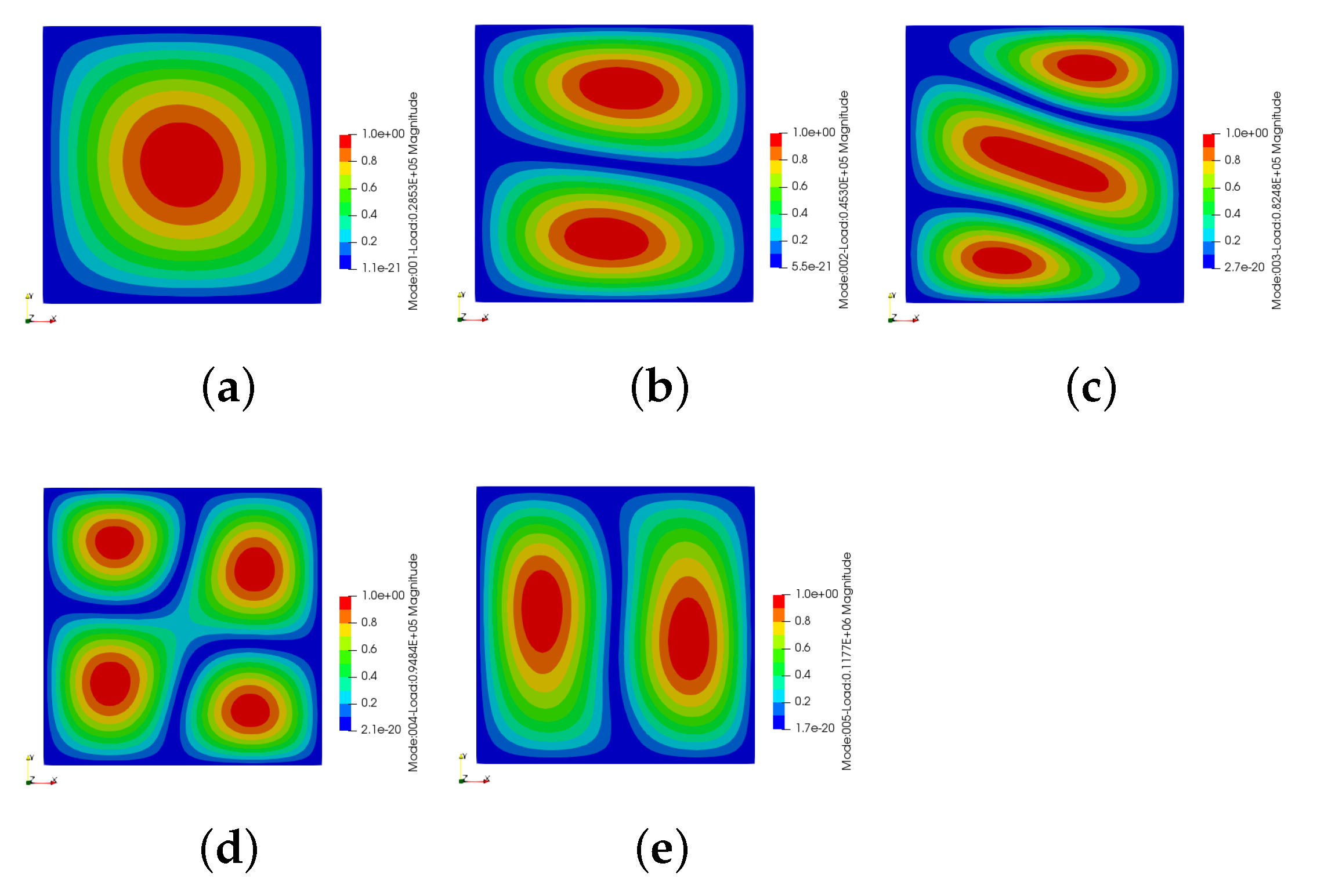
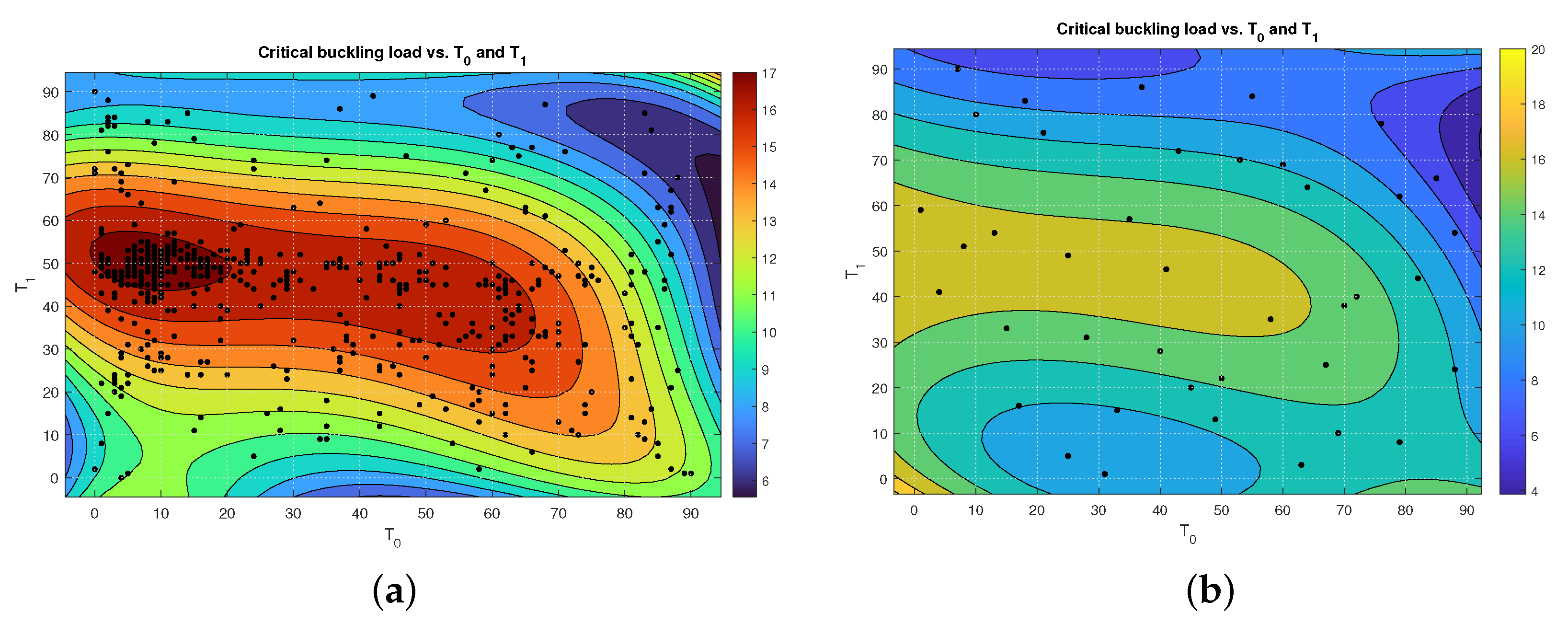
5.1. Buckling Results of VAT Laminate

As mentioned before, VAT laminates were made with [ < 60 | 15 > < 60 | 15 > / < 60 | 15 > < 60 | 15 > ] s square and symmetrical laminates based on the reference paper [44,51,57]. To begin, the V A T 1 composite plate was built in a 1D CUF framework with a diverse set of beams that are suitable and valid based on the design criteria and specifications. The accuracy of the models improved as the number of L 9 elements in the cross-section (Figure 6a) and three-node beam element ( B 3 ) in the beam length (Figure 7a) increased. The monolithic convergence properties of beam elements were demonstrated by the refining of beam elements for buckling load investigation. Furthermore, the degree of freedom (DOF) in FEM (ABAQUS) decreased greatly in comparison with CUF without a significant error; see Figure 6b and Figure 7b [44,51]. The first buckling load with the 10 B 3 element was picked as a sufficiently accurate result for further evaluation to save time during the optimization procedure.
Through GA, an optimal distribution of the fiber angles of VAT ( T 0 and T 1 ) was obtained for the maximum buckling load subjected to a simply supported boundary condition. The optimization procedure is based on the proposed linear equation of the fiber orientation angle (Equation (15)) to design VAT plates for the maximum buckling load. A sufficiently large population and generation were employed to avoid the local optimization decisions. As mentioned in Table 3, the population size in the GA was set to 50, which means evaluating 50 functions per generation. In this study, the convergence of optimum results was obtained after 20 iterations; thus, 20 × 50 = 1000 function evaluations were investigated.
The total number of cost functions in this problem could be 9116. Therefore, the significant cost reduction from 9116 to 1000 shows the efficiency of the GA method for stacking sequence optimization.
The optimum results obtained VAT laminates ( V A T O P T ) with the layup [ < 9 | 51 > < 9 | 51 > / < 9 | 51 > < 9 | 51 > ] 4 , which indicated the maximum buckling load among the optimization procedures with respect to the initial buckling load based on V A T 1 ([44,51]) and classical laminates. The optimal design shows a small fiber angle ( 9 ) at the center of the laminates that extends to 51 at the edges. The VAT laminate with an optimum fiber orientation angle is illustrated for various layup designs in Figure 8. V A T O P T improves its buckling load compared to classical composite laminates and V A T 1 . The first modes of the buckling load as well as the amount of displacement range also are shown in Figure 9, with different colors indicating different layouts. The first five buckling loads are shown in Figure 10.
In addition, distribution plots are used to show the relationship and convergence between the pair of variables and the results based on the GA sample points; see Figure 11.

Reduction of Search Domain by Latin Hypercube Method

To reduce the timing burden in finding the optimum, the Latin hypercube sampling (LHS) method can be used to generate some samples uniformly distributed in the search domain based on [54,58] and then to be compared with GA. After capturing the results from these samples, a high-order polynomial was used as a response surface model over the LHS samples. In parallel, a response surface also was used to show the GA events. The input variable parameters in both methods were T 0 and T 1 . Through GA, 798 samples were recorded during the optimization procedure while in LHS, only 40 different samples were generated in a randomly space-filling approach. By comparing the curve fitting obtained from GA and LHS methods in Figure 12, it was concluded that the domain of the global optimum, which is evident in the GA results, is well characterized by the LHS method with a small number of samples (black dots indicate all sample points). Therefore, LHS can be used to capture the specific domain of the optimum by a small computational effort. Accordingly, the LHS method can reduce the computational cost of the optimization by reducing the searching domain. As was suggested by Alinejad et al. [36,59], in the current study as well, the LHS can be used as an efficient method in the first step of optimization before using the GA or direct search methods in such problems. By this method, a large part of the search domain is eliminated from the remainder of the process.
Consequently, it is highly suggested for the next research that in such optimization problems, the Latin hypercube sampling method should be used first to reduce the searching domain before using other optimization methods (such as GA, gradient base, direct search, etc.) to reduce the computational costs.

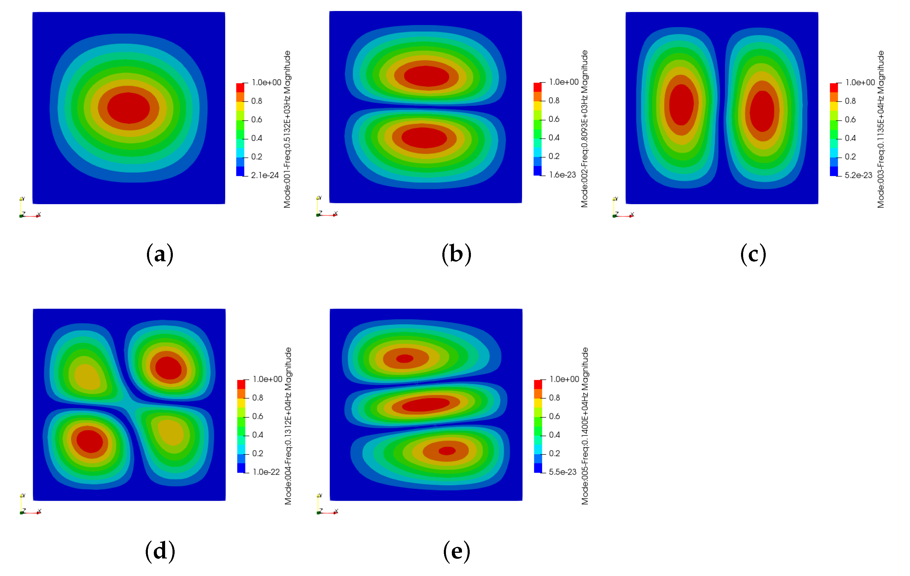
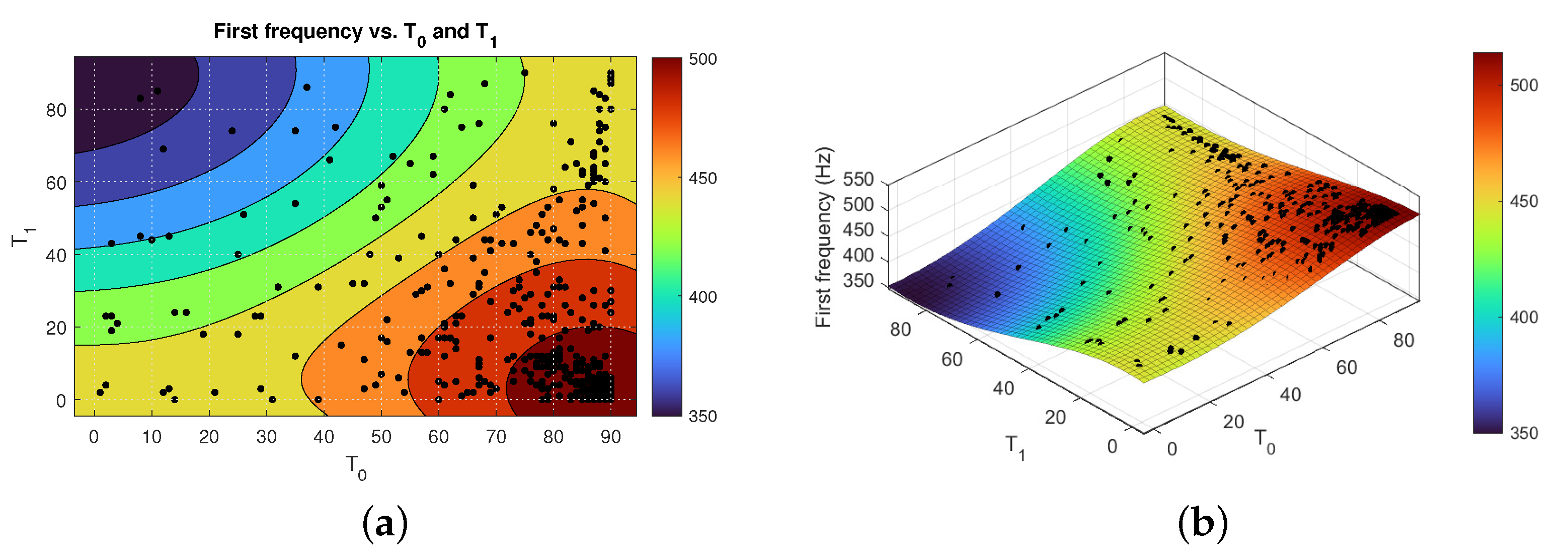
5.2. Results of VAT Laminate in Free Vibration

Based on the previous research [44], the same fully clamped plate of laminated VAT in free vibration analysis was chosen to study for the current evaluation: the optimization of VAT laminates through natural frequency analysis. Additionally, Q I , C S 1 , and C S 2 (Table 2) were used to demonstrate the ability of the optimization procedure and structural analysis of CUF in the LW model. In this study, the mesh with 160 L 9 on the cross-section was used. GA was applied to optimize the fiber orientation based on the highest first natural frequency. Contrary to the optimal results, the first natural frequency of different laminates is reported in Table 4. The first modal shape for different laminates is indicated in Figure 13. The optimal laminate has [ < 90 | 0 > < 90 | 0 > / < 90 | 0 > < 90 | 0 > ] 4 . This means that the start of T 0 has been reduced from 90 at the center to 0 at the edges of the VAT square plate. The five natural frequencies of the optimal laminates are shown in Figure 14.
Bar plots in Figure 15 show the relationships between variable pairs and the first natural frequency. In Figure 15, plots show that both T 0 and T 1 are highly dependent on the first natural frequency.
Figure 16 presents the result of the optimization obtained through GA, which was achieved by the fourth-order polynomial function based on the RS. The black dots show all of the sample points in the generation cycles. The colony of black dots is located in the optimal area (red part), which displays the convergence of the optimal results.

6. Conclusions

In this research, methodologies based on the Carrera unified formulation method were presented for the buckling and free vibration analysis of variable angle tow plates. The approaches are applicable to different boundary conditions and were found to be computationally less expensive compared with FEM. The numerical results on VAT plates with a linear variation of fiber angles demonstrated the accuracy and fast convergence of that approach.
For the first time, a global optimization method (GA) was applied with a combination of the layerwise theory, which was implemented through the CUF approach. The optimization was performed for maximizing the buckling load, and the results showed a significant improvement in comparison with results that were considered as reference VAT plates in FEM. Consequently, the advantages of using this presentation for free vibration analysis were demonstrated. The study of the optimization of the buckling load in SSSS and free vibration analysis under the CCCC boundary condition of VAT highlighted the ability of CUF methodologies to enhance the buckling and frequency response of VAT composite laminates. Furthermore, a post-processing RS showed the ability of GA for the convergence of results for VAT problems in different analyses. Moreover, LHS is proposed for its advantage when used for the initial sampling methodologies of GA for future research to minimize the computational cost of GA.

Funding

This research received no external funding.

Institutional Review Board Statement

Not applicable.

Informed Consent Statement

Not applicable.

Data Availability Statement

Not applicable.

Conflicts of Interest

The author declares no conflict of interest. The funder had no role in the design of the study; in the collection, analyses, or interpretation of data; in the writing of the manuscript; or in the decision to publish the results.

Abbreviations

The following abbreviations are used in this manuscript:
1DOne-Dimensional
CUFCarrera Unified Formulation
VATVariable Angle Tow
LWLayer Wise
GAGenetic Algorithm
CLTClassical Laminate Theory
DQMDifferential Quadrature Method
FEMFinite Element Method
RSResponse Surface
LHSLatin Hypercube Sampling
FNFundamental Nucleus
BCBoundary Condition
QIQuasi-Isotropic
CSConstant Stiffness
DOFDegree Of Freedom

References

  1. Gürdal, Z.; Tatting, B.F.; Wu, C.K. Variable stiffness composite panels: Effects of stiffness variation on the in-plane and buckling response. Compos. Part A Appl. Sci. Manuf. 2008, 39, 911–922. [Google Scholar] [CrossRef]
  2. Hyer, W.M.; Lee, H.H. The use of curvilinear fiber format to improve buckling resistance of composite plates with central circular holes. Compos. Struct. 1991, 18, 239–261. [Google Scholar] [CrossRef]
  3. Gürdal, Z.; Olmedo, R. In-plane response of laminates with spatially varying fiber orientations—Variable stiffness concept. AIAA J. 1993, 31, 751–758. [Google Scholar] [CrossRef]
  4. Leissa, A.W.; Martin, A.F. Vibration and buckling of rectangular composite plates with variable fiber spacing. Compos. Struct. 1990, 14, 339–357. [Google Scholar] [CrossRef]
  5. Vescovini, R.; Dozio, L. A variable-kinematic model for variable stiffness plates: Vibration and buckling analysis. Compos. Struct. 2016, 142, 15–26. [Google Scholar] [CrossRef]
  6. Demasi, L.; Ashenafi, Y.; Cavallaro, R.; Santarpia, E. Generalized Unified Formulation shell element for functionally graded Variable-Stiffness Composite Laminates and aeroelastic applications. Compos. Struct. 2015, 133, 501–515. [Google Scholar] [CrossRef]
  7. Olmedo, R.; Gürdal, Z. Buckling response of laminates with spatially varying fiber orientations. Struct. Dyn. Mater. Conf. Struct. 1993, 1567. [Google Scholar] [CrossRef]
  8. Tatting, B.; Gürdal, Z. Analysis and design of tow-steered variable stiffness composite laminates. In Proceedings of the American Helicopter Society Hampton Roads Chapter, Structure Specialists’ Meeting, Williamsburg, VA, USA, 30 October–1 November 2001. [Google Scholar]
  9. Raju, G.; Wu, Z.; Kim, B.C.; Weaver, P.M. Prebuckling and buckling analysis of variable angle tow plates with general boundary conditions. Compos. Struct. 2012, 94, 2961–2970. [Google Scholar] [CrossRef] [Green Version]
  10. Raju, G.; Wu, Z.; Kim, B.C.; Weaver, P.M. Analysis of Tow-Placed, Variable-Stiffness Laminates. Master’s Thesis, Virginia Tech, Blacksburg, VA, USA, 1996. [Google Scholar]
  11. Chen, X.; Nie, G. Prebuckling and buckling analysis of moderately thick variable angle tow composite plates considering the extension-shear coupling. Compos. Struct. 2012, 242, 112093. [Google Scholar] [CrossRef]
  12. Coburn, B.H.; Wu, Z.; Weaver, P.M. Buckling analysis of stiffened variable angle tow panels. Compos. Struct. 2014, 111, 259–270. [Google Scholar] [CrossRef] [Green Version]
  13. Coburn, B.H.; Weaver, P.M. Buckling analysis, design and optimisation of variable-stiffness sandwich panels. Int. J. Solids Struct. 2016, 96, 217–228. [Google Scholar] [CrossRef] [Green Version]
  14. Hachemi, M.; Hamza-Cherif, S.M.; Houmat, A. Free vibration analysis of variable stiffness composite laminate plate with circular cutout. Aust. J. Mech. Eng. 2020, 18, 63–79. [Google Scholar] [CrossRef]
  15. Sciascia, G.; Oliveri, V.; Milazzo, A.; Weaver, P.M. Ritz Solution for Transient Analysis of Variable-Stiffness Shell Structures. Mech. Adv. Mater. Struct. 2020, 58, 1796–1810. [Google Scholar] [CrossRef]
  16. Carrera, E.; Cinefra, M.; Petrolo, M.; Zappino, E. Finite Element Analysis of Structures Through Unified Formulation. In Mechanics of Advanced Materials and Structures; John Wiley & Sons: Hoboken, NJ, USA, 2014. [Google Scholar]
  17. Carrera, E.; Giunta, G.; Petrolo, M. Beam Structures: Classical and Advanced Theories; John Wiley & Sons: Hoboken, NJ, USA, 2017. [Google Scholar]
  18. Carrera, E. Evaluation of Layerwise Mixed Theories for Laminated Plates Analysis. AIAA J. 1998, 36, 830–839. [Google Scholar] [CrossRef]
  19. Carrera, E.; Azzara, R.; Daneshkhah, E.; Pagani, A.; Wu, B. Buckling and post-buckling of anisotropic flat panels subjected to axial and shear in-plane loadings accounting for classical and refined structural and nonlinear theories. Int. J. Non-Linear Mech. 2021, 133, 103716. [Google Scholar] [CrossRef]
  20. Carrera, E.; Pagani, A.; Valvano, S. Shell elements with through-the-thickness variable kinematics for the analysis of laminated composite and sandwich structures. Compos. Part B Eng. 2017, 111, 294–314. [Google Scholar] [CrossRef] [Green Version]
  21. Pagani, A.; Valvano, S.; Carrera, E. Analysis of laminated composites and sandwich structures by variable-kinematic MITC9 plate elements. J. Sandw. Struct. Mater. 2018, 20, 4–41. [Google Scholar] [CrossRef] [Green Version]
  22. Pagani, A.; Daneshkhah, E.; Xu, X.; Carrera, E. Evaluation of geometrically nonlinear terms in the large-deflection and post-buckling analysis of isotropic rectangular plates. Int. J. Non-Linear Mech. 2020, 121, 103461. [Google Scholar] [CrossRef]
  23. Xu, X.; Fallahi, N.; Yang, H. Efficient CUF-based FEM analysis of thin-wall structures with Lagrange polynomial expansion. Mech. Adv. Mater. Struct. 2020, 1–22. [Google Scholar] [CrossRef]
  24. Tahani, M. Analysis of laminated composite beams using layerwise displacement theories. Compos. Struct. 2007, 79, 535–547. [Google Scholar] [CrossRef]
  25. Entezari, A.; Kouchakzadeh, M.A.; Carrera, E.; Filippi, M. A refined finite element method for stress analysis of rotors and rotating disks with variable thickness. Acta Mech. 2017, 228, 575–594. [Google Scholar] [CrossRef]
  26. Carrera, E.; Entezari, A.; Filippi, M.; Kouchakzadeh, M.A. 3D thermoelastic analysis of rotating disks having arbitrary profile based on a variable kinematic 1D finite element method. J. Therm. Stress. 2017, 39, 1572–1587. [Google Scholar] [CrossRef]
  27. Georgantzinos, S.K.; Giannopoulos, G.I.; Markolefas, S.I. Vibration Analysis of Carbon Fiber-Graphene-Reinforced Hybrid Polymer Composites Using Finite Element Techniques. Materials 2020, 13, 4225. [Google Scholar] [CrossRef]
  28. Georgantzinos, S.K.; Antoniou, P.A.; Giannopoulos, G.I.; Fatsis, A.; Markolefas, S.I. Design of Laminated Composite Plates with Carbon Nanotube Inclusions against Buckling: Waviness and Agglomeration Effects. Nanomaterials 2020, 11, 2261. [Google Scholar] [CrossRef] [PubMed]
  29. Uthale, S.A.; Dhamal, N.A.; Shinde, D.K.; Kelkar, A.D. Polymeric hybrid nanocomposites processing and finite element modeling: An overview. Sci. Prog. 2021, 18, 165–188. [Google Scholar] [CrossRef]
  30. Tsai, S.W.; Halpin, J.C.; Pagano, N.J. Composite Materials Workshop; Conn., Technomic Pub. Co.: St. Louis, MO, USA, 1968.
  31. Setoodeh, S.; Abdalla, M.M.; IJsselmuiden, S.T.; Gürdal, Z. Design of variable-stiffness composite panels for maximum buckling load. Compos. Struct. 2009, 87, 109–117. [Google Scholar] [CrossRef]
  32. Fukunag, H.; Vanderplaats, G.N. Stiffness optimization of orthotropic laminated composites using lamination parameters. AIAA J. 1991, 29, 641–646. [Google Scholar] [CrossRef]
  33. Liu, B.; Haftka, R.T.; Trompette, P. Maximization of buckling loads of composite panels using flexural lamination parameters. Struct. Multidiscip. Optim. 2004, 26, 28–36. [Google Scholar] [CrossRef]
  34. Bloomfield, M.W.; Herencia, J.E.; Weaver, P.M. Enhanced two-level optimization of anisotropic laminated composite plates with strength and buckling constraints. Thin-Walled Struct. 2009, 47, 1161–1167. [Google Scholar] [CrossRef]
  35. Tawfik, M.E.; Bishay, P.L.; Sadek, E.A. Neural Network-Based Second Order Reliability Method (NNBSORM) for Laminated Composite Plates in Free Vibration. Comput. Model. Eng. Sci. 2018, 115, 105–129. [Google Scholar]
  36. Alinejad, F.; Botto, D. Innovative adaptive penalty in surrogate-assisted robust optimization of blade attachments. Acta Mech. 2019, 230, 2735–2750. [Google Scholar] [CrossRef]
  37. Forrester, A.I.J.; Keane, A.J. Recent advances in surrogate-based optimization. Prog. Aerosp. Sci. 2009, 45, 50–79. [Google Scholar] [CrossRef]
  38. Zhou, X.Y.; Ruan, X.; Gosling, P.D. Robust design optimization of variable angle tow composite plates for maximum buckling load in the presence of uncertainties. Compos. Struct. 2019, 223, 110985. [Google Scholar] [CrossRef]
  39. Holland, J.H. Adaptation in Natural and Artificial Systems: An Introductory Analysis with Applications to Biology, Control, and Artificial Intelligence; MIT Press: Cambridge, MA, USA, 1992. [Google Scholar]
  40. Nikbakt, S.; Kamarian, S.; Shakeri, M. A review on optimization of composite structures Part I: Laminated composites. Compos. Struct. 2018, 195, 158–185. [Google Scholar] [CrossRef]
  41. Esposito, M.; Gherlone, M. Material and strain sensing uncertainties quantification for the shape sensing of a composite wing box. Mech. Syst. Signal Process. 2021, 160, 107875. [Google Scholar] [CrossRef]
  42. Viglietti, A.; Zappino, E.; Carrera, E. Free vibration analysis of variable angle-tow composite wing structures. Aerosp. Sci. Technol. 2019, 92, 114–125. [Google Scholar] [CrossRef]
  43. Viglietti, A.; Zappino, E.; Carrera, E. Analysis of variable angle tow composites structures using variable kinematic models. Compos. Part B Eng. 2019, 171, 272–283. [Google Scholar] [CrossRef]
  44. Fallahi, N.; Viglietti, A.; Carrera, E.; Pagani, A.; Zappino, E. Effect of fiber orientation path on the buckling, free vibration, and static analyses of variable angle tow panels. Facta Univ. Ser. Mech. Eng. 2020, 18, 165–188. [Google Scholar] [CrossRef]
  45. Carrera, E.; Pagani, A.; Cabral, P.H.; Prado, A.; Silva, G. Component-Wise Models for the Accurate Dynamic and Buckling Analysis of Composite Wing Structures. In Proceedings of the ASME 2016 International Mechanical Engineering Congress and Exposition, Phoenix, AZ, USA, 11–17 November 2016. [Google Scholar]
  46. Carrera, E.; Petrolo, M. Refined beam elements with only displacement variables and plate/shell capabilities. Meccanica 2012, 47, 537–556. [Google Scholar] [CrossRef]
  47. Reddy, J.N. An evaluation of equivalent-single-layer and layerwise theories of composite laminates. Compos. Struct. 1993, 25, 21–35. [Google Scholar] [CrossRef]
  48. Borst, R.D.; Crisfield, M.A.; Remmers, J.J.C.; Verhoosel, C.V. Nonlinear Finite Element Analysis of Solids and Structures; John Wiley & Sons: Hoboken, NJ, USA, 2012. [Google Scholar]
  49. Tatting, B.F.; Gürdal, Z. Design and Manufacture of Elastically Tailored Tow Placed Plates. NASA/CR-2002-211919. 2020. Available online: https://ntrs.nasa.gov/citations/20020073162 (accessed on 7 September 2013).
  50. Hyer, M.W.; Charette, R.F. The use of curvilinear fiber format in composite structure design. In Proceedings of the 30th Conference on Structures, Structural Dynamics and Materials, Mobile, AL, USA, 3–5 April 1989. [Google Scholar]
  51. Hao, P.; Yuan, X.; Liu, H.; Wang, B.; Liu, C.; Yang, D.; Oan, S. Isogeometric buckling analysis of composite variable-stiffness panels. Compos. Struct. 2017, 165, 192–208. [Google Scholar] [CrossRef]
  52. Daneshkhah, E.; Nedoushan, R.J.; Shahgholian, D.; Sina, N. Cost-Effective Method of Optimization of Stacking Sequences in the Cylindrical Composite Shells Using Genetic Algorithm. Eur. J. Comput. Mech. 2020, 29-1, 115–138. [Google Scholar] [CrossRef]
  53. Ashenden, P.J.; Peterson, G.D.; Teegarden, D.A. Chapter twenty-five—Integrated System Modeling. In The System Designer’s Guide to VHDL-AMS, System and Silicon; Morgan Kaufmann: Burlington, MA, USA, 2003; pp. 735–750. [Google Scholar]
  54. Fan, Y.; Hu, W.; Li, G. Variable stiffness composite material design by using support vector regression assisted efficient global optimization method. Struct. Multidiscip. Optim. 1993, 56, 203–219. [Google Scholar]
  55. Arian Nik, M.; Fayazbakhsh, K.; Pasini, D.; Lessard, L. Surrogate-based multi-objective optimization of a composite laminate with curvilinear fibers. Compos. Struct. 2012, 94, 2306–2313. [Google Scholar] [CrossRef] [Green Version]
  56. Arian Nik, M.; Fayazbakhsh, K.; Pasini, D.; Lessard, L. Optimization of variable stiffness composites with embedded defects induced by Automated Fiber Placement. Compos. Struct. 2014, 107, 160–166. [Google Scholar] [CrossRef] [Green Version]
  57. Fallahi, N.; Carrera, E.; Pagani, A. Application of GA Optimization in Analysis of Variable Stiffness Composites. Facta Univ. Ser. Mech. Eng. 2021, 15, 65–70. [Google Scholar]
  58. Botto, D.; Alinejad, F. Innovative design of attachment for turbine blade rotating at high speed. In Proceedings of the ASME Turbo Expo 2017: Turbomachinery Technical Conference and Exposition, Charlotte, NC, USA, 26–30 June 2017. [Google Scholar]
  59. Alinejad, F.; Botto, D.; Gola, M.; Bessone, A. Reduction of the design space to optimize blade fir-tree attachments. In Proceedings of the ASME Turbo Expo 2018: Turbomachinery Technical Conference and Exposition, Oslo, Norway, 11–15 June 2018; Volume 165, pp. 192–208. [Google Scholar]
Figure 1. The modeling of a beam structure using a 1D model where y is the along the beam axis, and the cross-section lies on the x–z plane through thickness.
Aerospace 08 00376 g001
Figure 2. Linear and cubic ESL and LW cases.
Aerospace 08 00376 g002
Figure 3. Variable angle tow plate.
Aerospace 08 00376 g003
Figure 4. SSSS boundary condition of the VAT plate.
Aerospace 08 00376 g004
Figure 5. Flowchart of genetic algorithm procedure (MATLAB) in combination with CUF approach (FORTRAN).
Aerospace 08 00376 g005
Figure 6. 1D CUF cross-section refinement with 10 B 3 influence on buckling load in V A T 1 in terms of FEM and degrees of freedom. (a) Cross-section refinement. (b) DOF based on cross-section refinement.
Aerospace 08 00376 g006
Figure 7. Refinement of a 1D CUF beam element with a 160 L 9 effect on the buckling load in V A T 1 in relation to the FEM and the number of degrees of freedom. (a) Beam refinement. (b) DOF based on beam refinement.
Aerospace 08 00376 g007
Figure 8. Comparison of different layup designs with the optimum outcome.
Aerospace 08 00376 g008
Figure 9. The first buckling modes in different laminates. (a) Q I : 13.79 kN. (b) C S 1 : 16.51 kN. (c) C S 2 : 10.12 kN. (d) V A T 1 : 13.77 kN. (e) V A T O P T : 17.38 kN.
Aerospace 08 00376 g009
Figure 10. The first five buckling modes of optimum VAT laminates. (a) Mode 1: 17.38 kN. (b) Mode 2: 27.38 kN. (c) Mode 3: 49.77 kN. (d) Mode 4: 57.36 kN. (e) Mode 5: 71.72 kN.
Aerospace 08 00376 g010
Figure 11. Distribution of variables and first critical buckling load, T 0 - T 1 ; first buckling load— T 0 , and first buckling load— T 1 .
Aerospace 08 00376 g011
Figure 12. Contour plots and response surfaces based on GA and LHS for T 0 and T 1 as the variables and first critical buckling load as the response. (a) GA contour plot of variables’ sample points ( F c r is represented by the colors). (b) LHS contour plot of variables’ sample points ( F c r is represented by the colors).
Aerospace 08 00376 g012
Figure 13. First natural frequency modes in various layup designs. (a) QI. (b) CS1. (c) CS2. (d) V A T 1 . (e) V A T O P T .
Aerospace 08 00376 g013
Figure 14. The first five natural frequency modes. (a) Mode 1: 513.15 Hz (b) Mode 2: 809.30 Hz. (c) Mode 3: 1135.00 Hz. (d) Mode 4: 1312.00 Hz (e) Mode 5: 1400.00 Hz.
Aerospace 08 00376 g014
Figure 15. Distribution of variables and first natural frequency; first natural frequency— T 0 , first natural frequency— T 1 .
Aerospace 08 00376 g015
Figure 16. During implementation of the GA technique in a free vibration issue, the contour plot and response surface reveal the impacts of variables (fiber orientation angles). (a) Colors represent the f 1 in this contour plot of variables. (b) Response surface.
Aerospace 08 00376 g016
Table 1. Mechanical properties of VAT material laminate.
E 1 (GPa) E 2 = E 3 (GPa) G 12 = G 13 (GPa) G 23 (GPa) ν 12
Material18110.2707.1703.7800.28
Table 2. Reference laminate lay-up design and the optimum VAT plate.
Laminated Scheme Layup Design
Q I [ 45 , 0 , 45 , 90 ] 2 S
C S 1 [ ± 45 ] 4 S
C S 2 [ 0 ] 16 T
V A T 1 [44,51] [ < 60 | 15 > < 60 | 15 > / < 60 | 15 > < 60 | 15 > ] 4
Table 3. Settings of genetic algorithm.
DescriptionMaximum Number of GenerationPopulation SizeCrossover PercentageMutation Rate
Value20500.80.04
Table 4. Frequency results for reference laminate lay-up designs in contrast to optimum VAT plate.
Laminated Scheme First Natural Frequency (Hz)
Q I 438.385
C S 1 433.064
C S 2 446.235
V A T 1 438.659
V A T O P T 513.159
Publisher’s Note: MDPI stays neutral with regard to jurisdictional claims in published maps and institutional affiliations.

