Article

Good Match between “Stop-and-Go” Strategy and Robust Guidance Based on Deep Reinforcement Learning

College of Aerospace Science and Engineering, National University of Defense Technology, Changsha 410072, China
*
Author to whom correspondence should be addressed.
Aerospace 2022, 9(10), 569; https://doi.org/10.3390/aerospace9100569
Submission received: 4 June 2022 / Revised: 6 September 2022 / Accepted: 27 September 2022 / Published: 29 September 2022

Abstract

:
This paper deals with the guidance problem of close approaching small celestial bodies while autonomously navigating with an optical camera. A combination of a deep reinforcement learning (DRL)-based guidance method and a “Stop-and-Go” (SaG) strategy is here proposed to increase the mission adaptability. Firstly, a robust guidance strategy optimizing fuel consumption and angle-only navigation (AON) observability is trained by DRL. Secondly, the SAG strategy is designed to introduce the mission adaptability and further improve the AON observability. Thirdly, a good match between the SAG strategy and the DRL-based robust guidance is demonstrated. The proposed method was tested in a typical R-bar approaching scenario. Then, the mission adaptability with an onboard application was successfully verified, investigating the policy performance with SAG.

1. Introduction

Mission adaptability is a crucial but challenging capability for small celestial body exploration. In proximity to small celestial bodies, the environment is extremely harsh and unknown. The close approach phase to small celestial bodies faces many uncertainties and even emergencies. In current small celestial body missions [1,2], the close approach process is usually highly supervised from the ground [3,4], and the ground is always ready to intervene to ensure mission safety.
However, after the close approach process is interfered with by the ground, the original approach trajectory is interrupted, and the original plan is abandoned. A re-approach process and trajectory needs to be re-planned on the ground. This kind of inflexibility reduces the efficiency of temporary task adjustment, and may make it impossible to continue to achieve the set goals after the suspension caused by emergencies. It is urgent to design a spacecraft navigation and guidance strategy to enhance mission adaptability, which will have a promising prospect in small celestial body missions.
The close approach phase sends the spacecraft to the proximity of asteroids, and then the spacecraft can carry out complex operation tasks. For example, Hayabusa2 started a descent operation from a home position where the distance from the near-Earth asteroid (NEA) Ryugu was 20 km after Hayabusa2 had arrived at the proximity of the asteroid [5,6]. Therefore, the close approach phase is vital for mission design [2,7,8]. Specifically, the requirement of the guidance, navigation, and control (GN & C) system is presented very stringently, especially in terms of accuracy and robustness. The terminal accuracy and the robustness to various uncertainty are essential to ensure mission safety and success [4].
“Robustness” of trajectory or guidance is not a new concept. Research on stochastic optimal control [9,10] and stochastic dynamic programming [11,12] have been very hot. There is fruitful research on designing robust trajectory, such as chance-constrained optimal control [13,14], stochastic differential dynamic programming (SDDP) [11,12], evidence theory [15], and belief-based transcription procedures for stochastic optimal control problems (SOCPs) [9,10].
In the past few years, machine learning has been very popular in the application of spacecraft guidance, navigation, and control (GN & C). Izzo et al. summarized the development trend of machine learning in the field of spacecraft guidance dynamics and control and predicted future research in 2019 [16]. Supervised learning, the oldest branch of machine learning, has also shown its robustness to uncertainties [17]. However, under uncertain environments and complex constraints, a sufficiently large data set of experts is usually required for supervised learning, which needs careful and intricate design to avoid overfitting. Reinforcement learning (RL) has gradually gained more attention [18], which can autonomously learn control strategies through its interaction with the environment. The trajectory design problem is modeled as a time-discrete Markov decision process (MDP). The learning procedure is realized by maximizing a user-defined function, that is, a reward function. The policy gradient is used to continuously improve the policy, which is used as a baseline as this was later improved through the years. Policy-gradient (PG) algorithms extend deep Q-learning (a finite set of actions) to the field of continuous control (continuous state and action spaces) [19]. To alleviate the problem of the large variance of a cumulative reward, the actor–critic (AC) method and the advantage actor–critic (A2C) method improve the policy-gradient algorithms based on approximating the Q-function using a second DNN and approximating the advantage function using a generalized advantage estimator [20]. The proximal policy optimization (PPO) algorithm further stabilizes the update of the policy by introducing a clipped function [21]. PPO has demonstrated state-of-the-art performances on many benchmark RL problems. PPO is widely used partially because it does not need any ad-hoc reward shaping. In recent years, RL has been applied to spacecraft GN & C, such as low-thrust trajectory design [22,23,24,25,26], formation flying [27], rendezvous or intercept guidance [28,29,30,31,32,33], asteroid hovering [34,35], planetary landing [36,37,38,39,40,41], etc. Among them, reinforcement meta learning based on recurrent neural network is used to solve the problems of partially observable Markov decision process (POMDP) and policy extrapolation in the context of continuing learning [37,42,43]. Deep convolutional neural network is used to map the raw observations, such as raw images, to a true inner state [32,40], which is also a means to solve the POMDP.
Line of sight (LOS) navigation and AON are heated topics in noncooperative rendezvous [44], and are also very popular in small celestial body missions, especially those based on CubeSat. On the one hand, AON only needs optical sensors, which can reduce the cost and weight. On the other hand, AON is completely passive and self-contained, working over a wide range of distances. These advantages of AON make it more suitable than microwave radar, laser radar, laser rangefinder, and other sensors. However, AON has a well-known problem of weak range direction observability, and it is necessary to improve the range direction observability by incorporating known orbital maneuvers into the navigation filter [45,46,47]. Several optimal single-step rendezvous guidance methods have been proposed together with different definitions of AON observability [46,47]. Moreover, an online guidance framework of multiple maneuvers to obtain optimal observability has also been proposed [45], which is similar to model predictive control and needs to be solved multiple times online [48,49].
However, these proposed rendezvous guidance methods are all carried out in a determined manner by building and then solving a deterministic optimal control problem. The robust guidance strategy based on DRL is also usually trained under a fixed number of maneuvers [31,33]. Once an optimal guidance or rendezvous trajectory is obtained, the number of maneuvers is fixed. If the number of maneuvers needs to be changed, the problem needs to be solved again. This is one of the reasons for the mentioned inadaptability problem.
We find that the “Stop-and-Go” (SaG) strategy has the ability to increase the number of orbital maneuvers while basically maintaining the geometry of the original trajectory [3,50]. The basic idea of SaG is as follows [3,50]: a breaking to zero followed by a new impulsive maneuver is performed at a middle waypoint, which is intended to further assist the AON observability in the range direction. However, differential-corrective guidance (fixed-time-of-arrival) is employed in original papers [3,50], which can be more sensitive to various uncertainties.
This paper proposes a close approach guidance method with more robustness and adaptability. A good match between SaG strategy and robust DRL-based guidance is used. Specifically, in order to improve the AON observability, the observability term is introduced into the reward function. A flexible SaG strategy is designed to freely insert the SaG point on the close approach trajectory. A framework combining the SaG strategy and the DRL-based guidance is proposed. The advantages of this framework are:
(1)
The spacecraft can stop at any time during the process of approaching the asteroid to respond to an emergency or avoid hazards, giving the approach process more flexibility;
(2)
The original robust guidance can still work after the SaG point without the need to solve the guidance policy again, and therefore improve the real-time performance;
(3)
It can increase the AON observability in the range direction and therefore ensure the terminal accuracy of rendezvous guidance.
The structure of this paper is organized as follows. First, a robust guidance method with enhanced AON observability based on DRL is introduced in Section 2. Then, Section 3 introduces the SaG strategy and the framework combining the SaG strategy and the DRL-based guidance. Then, some simulation results in a typical R-bar approaching scenario are given in Section 4, and the mission adaptability with an onboard application is verified. Finally, Section 5 concludes with some interesting findings.

2. Robust Guidance Method with Enhanced AON Observability Based on DRL

2.1. Close Approach Phase

The reference task is an asteroid close approach rendezvous mission. For simplification, the spacecraft and the asteroid are assumed to follow a Kepler dynamic model under the sole influence of the sun’s gravity. This assumption holds true for the spacecraft when the gravity of the asteroid and the solar radiation pressure (SRP) are very small compared to the gravity difference of the sun, which means that the asteroid is very small in size and mass (like with a diameter smaller than 5 m), and that the area–mass ratio of the spacecraft is very small. The gravity acceleration due to the small body and the SRP acceleration can be considered in the dynamic model for a more general scenario, which will be included in future work. To describe the relative motion between a spacecraft and an asteroid, the coordinate systems shown in Figure 1 are established, including the asteroid Hill rotation coordinate system O a x y z and the heliocentric inertial coordinate system O s X Y Z . The spacecraft and asteroid can be regarded as points.
The center O a is at the barycenter of the asteroid. O a x y z rotates at the orbital angular velocity ω relative to O s X Y Z . Its basic plane is the asteroid orbital plane, and O a x y z is defined as follows:
(1)
The x axis is along the orbit radius.
(2)
The z axis follows the angular momentum direction of the asteroid’s orbit.
(3)
The y axis completes the right-handed coordinate system and is perpendicular to the x axis in the orbital plane.
The unit vector corresponding to the asteroid Hill rotation coordinate system O a x y z is { i x ,   i y ,   i z } , and the unit vector corresponding to the heliocentric inertial coordinate system O s X Y Z is { i X ,   i Y ,   i Z } .
The relative position vector r = [ x y z ] T is defined in the asteroid Hill rotation coordinate system, as shown in Figure 1. The spacecraft state x is described by the relative position r = [ x y z ] T and its time derivative v = r ˙ = [ x ˙ y ˙ z ˙ ] T , that is, x = [ r T v T ] T . The state x is propagated by means of the orbital relative motion equation. The Clohessy–Wiltshire (C–W) equation can be used under the assumption of a circular orbit and short rendezvous times [38], and the Tschauner–Hempel (T–H) equation [51] can be used under the assumption of an elliptical orbit. After orbital maneuver u , the relative motion equation can be written as follows:
x ( t ) = Φ ( t ) x 0 + G ( t ) u
Equation (1) is defined in the asteroid Hill rotation coordinate system, where x 0 is the state vector at the initial maneuver time, and x is the state vector at time t after an impulse maneuver. Φ ( t ) is the state transition matrix, and the specific form of Φ ( t ) depends on which of the C–W equation [47] or the T–H equation [52] is used. Since 2016HO3 (with the orbital eccentricity larger than 0.1) is adopted as the object asteroid in simulations, the T–H equation is chosen in this paper. For the derivation of the T–H equation and the detailed expression of Φ ( t ) , please refer to Refs. [51,52].
The input matrix G ( t ) in the case of an impulse maneuver is defined as Columns 4–6 of Φ ( t ) , that is,
G ( t ) = Φ ( t ) [ 1 : 6 , 4 : 6 ] = [ G r G v ]
Φ = [ Φ r Φ v ]

2.2. Markov Decision Process (MDP)

First, the general mathematical form of the discrete-time MDP is briefly introduced. The MDP is generally composed of state, observation, action, state transition, and reward. Specifically, an MDP is discretized into N discrete time steps, [ t k , t k + 1 ] , k [ 0 , N 1 ] . Let s k S n be the state vector of the spacecraft’s relative motion at time t k , where S is the state space. Generally, s k cannot be directly obtained by the controller, but be estimated or observed as an observation through a navigation filter. Let o k O m be the observation of the relative motion state s k at time t k , where O is the observation space. In the scenario of close approaching small celestial bodies, especially those with a diameter of less than 5 m, AON is one of desired options because AON only needs optical sensors and can work over a wide range of distances. Since adding the complete AON process to the DRL will greatly slow down the training speed, we decided not to use the real AON process to obtain o k . On the contrary, the direct state observation is assumed. Specifically, the modeling of the state observation is based on introducing a manually designed noise inspired by the prior knowledge of AON performance, rather than a fixed Gaussian distribution additive noise. This will be explained in more detail in Section 2.3. Let a k A l be the control command defined as the output of the state feedback controller at time t k , where A is the action space. Let π : O A be the state feedback control policy; then, a k = π ( o k ) . Let f : s k , a k s k + 1 be the state transition function of the system, which can be described by a discrete-time CW equation. Let R k be the reward obtained during the transition from s k to s k + 1 under a k . A discount factor γ [ 0 , 1 ] is used to describe the fading of the current instantaneous reward’s importance to the future. For instance, let γ be close to 1 when it is very important in the long run, and let γ be close to 0 when it is only important in the short term. Let e = { ( s 0 , a 0 ) , , ( s N 1 , a N 1 ) } be one round of the trajectory episode obtained according to state feedback control strategy π . The objective of RL is to solve the optimal state feedback control strategy π * by optimizing a designed performance index, which is the sum of the expected value of the sum of R k along trajectory episode e with discount factor γ , that is,
J = 𝔼 τ ~ π [ k = 0 N 1 γ k R k ]
The above MDP is used to model a spacecraft close approach rendezvous. Considering a rendezvous mission with fixed time t f , the rendezvous is discretized into N time steps uniformly with step size Δ T = t f / N . Then, state s k , k [ 0 , N ] is defined as the relative motion state x at time t k = k Δ T , that is,
s k = x ( t k ) 6
If impulse maneuver u in Equation (2) occurs at time t k = k Δ T and state x is considered at time t k + 1 = ( k + 1 ) Δ T , then Equation (2) can be used to describe the transition of the state between two pulses. In this case, u k is the action a k taken at time t k , and Equation (1) can be reformed as
x k + 1 = Φ x k + G u k , k = 0 , 1 , , N 1
where x k x ( t k ) , Φ Φ ( Δ T ) , G G ( Δ T ) , and Δ T are omitted if there is no ambiguity. Φ and G are both constant matrixes.
At final time step t N = t f , according to the terminal velocity constraint and the maximum thrust constraint, the final thrust u N is calculated as follows:
u N = min ( | v f v N | , Δ v max , N ) v f v N | v f v N |
where Δ v max , N is the maximum thrust.
The spacecraft terminal state is defined as:
r f = r N
v f = v N + u N
The indeterminable state observation at time t k is defined as:
o k = [ r k T , v k T ] T 6

2.3. Observation Uncertainty Analysis and Modeling

The relative position and velocity of a spacecraft cannot be obtained directly by a controller, so it is necessary to observe or estimate the relative position and velocity using a navigation filter. In AON, additional maneuvers will be used to assist convergence of the navigation filter [52]. In spacecraft rendezvous, there is a quantified minimum navigation accuracy rule, the 1% range rule, which is that the relative navigation accuracy needs to be guaranteed to be at least 1% of the relative distance [46]. When the navigation has not converged, the navigation error can be more than 10% of the relative range and can be less than 0.5% after convergence. In this study, instead of incorporating the full navigation process into the MDP and the training of RL, which can be time-consuming, we simplify it as a direct observation of the states with noise representing navigation errors.
Observation uncertainty is here modeled as a time-varying Gaussian additive noise, and the observation at time t k can be defined as:
o k = x k + ω o , k
ω o , k = [ δ r o , k δ v o , k ] Ν ( 0 6 × 1 , Σ o , k ) 6
where Σ o , k = d i a g ( σ r , o , k 2 I 3 × 3 , σ v , o , k 2 I 3 × 3 ) is the covariance matrix. σ r , o , k and σ r , o , k are the standard deviations of velocity and position, respectively. More consideration will be given to σ r , o , k as follows:
σ r , o , k = { 10 % r   k k c σ p r   k > k c
where r is the relative distance, and σ p r can be adjusted according to the performance of AON. k c is the time step where the navigation filter converges. In this paper, k c = 2 .

2.4. Constraints Analysis and Modeling

The actual thrust limit of a thruster can be modeled using a thrust amplitude constraint. For an impulse maneuver, the thrust amplitude constraint can be described by the maximum impulse velocity. The amplitude of any impulse shall be less than or equal to the maximum value Δ v max , i.e.,
u k Δ v max
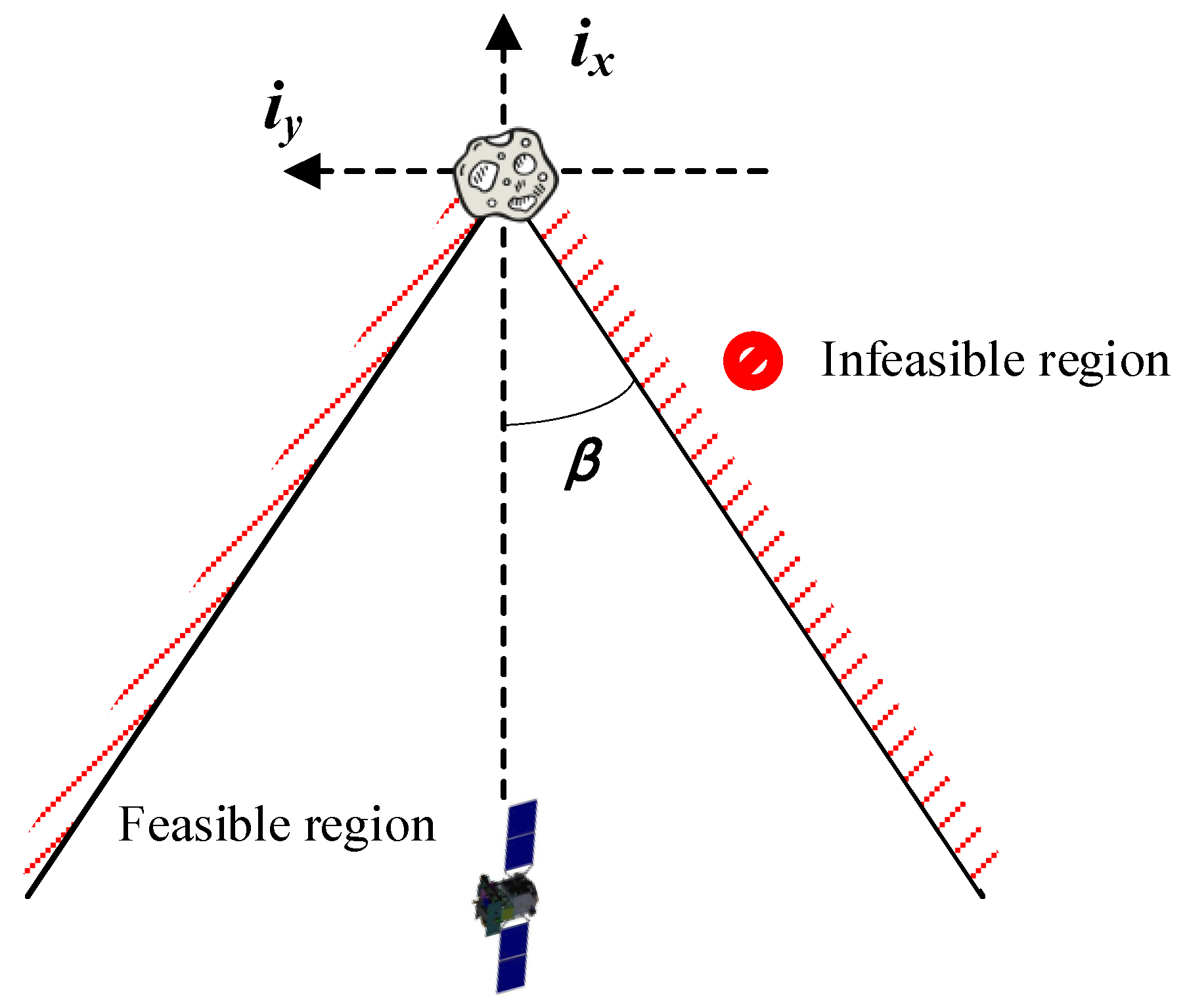
During an asteroid close approach rendezvous, the approach direction of the spacecraft is constrained by a visibility cone. As shown in Figure 2, the projection of the visibility cone in the xy plane shows how the motion of spacecraft is constrained by a cone half-angle of β . At time t k , the three-dimensional approach visibility cone constraint can be expressed as:
{ y k + x k tan β 0 y k + x k tan β 0 z k + x k tan β 0 z k + x k tan β 0
It can be written in matrix form as:
B x k 0 4 × 1
where
Β = [ tan β 1 0 0 0 0 tan β 1 0 0 0 0 tan β 0 1 0 0 0 tan β 0 1 0 0 0 ]
For different approach directions, the inequalities can be generalized by shifting and rotating the cone.

2.5. Reward Function Design

Geometrically, to improve the observability of AON, orbital maneuvers must change the LOS at less an observation angle θ . In this study, the observability criteria in [45] are adopted. At time t k , when the spacecraft state is x k , the linear independence between the relative position vector x ¯ k + 1 p = Φ r x k obtained without an orbit maneuver and the relative position vector x k + 1 p = Φ r x k + G r u k obtained with an orbit maneuver should be maximized. Therefore, the dot product J o , k of x ¯ k + 1 p and x k + 1 p should be minimized and
J o , k = ( Φ r x k ) T ( Φ r x k + G r u k ) = | Φ r x k | | Φ r x k + G r u k | cos θ
Since the spacecraft should not fly past the target after the orbital maneuver, Equation (18) should also obey
J o , k > 0
In addition, it is also necessary to meet the constraints of position and velocity of the terminal interception, maximum thrust amplitude, and visibility cone angle and punish any violated constraint.
Multiobjective optimization seeks a balanced compromise between multiple optimal objectives. Therefore, there is no unique optimal solution but rather a Pareto optimal solution set. The improvement of solutions in this solution set on one goal is at the cost of reducing another goal. A simple processing method designs the optimization objective as a weighted sum of multiple objectives. Therefore, the instantaneous reward R k obtained at time t k is
R k = u k N Δ v max λ 1 C o , k 50 N λ 2 e a , k λ 3 max ( 0 , e x , k + 1 ε ) λ 4 max ( 0 , e b , k + 1 ε )
where
C o , k = { J o , k    J o , k > 0 10000    J o , k 0
e a , k = max { 0 , u k / Δ v max 1 }
e x , k = { 0 max { r N r f / r ¯ , v N v f / v ¯ }   k < N k = N
e b , k = max { 0 , max { B x k } / r ¯ }
where e a , k is the penalty for violating the maximum thrust amplitude constraint, e x , k is the penalty for violating the terminal constraints, and e b , k is the penalty for violating the visibility cone constraint. The penalty for J o , k 0 is incorporated into the C o , k . r ¯ = 1   k m and v ¯ = 0.01   k m / s are normalization factors. ε represents the tolerance for the violation of constraints and constraints should be tightened with training, so the penalty relaxation factor should be decreased as
ε ( t ) = { 5 × 10 2 5 × 10 4   t T / 2 t > T / 2
λ 1 , λ 2 , λ 3 , λ 4 are the weight factors of the corresponding items in the reward function with typical values λ 1 = 0 .1 , λ 2 = 100 , λ 3 = 1 , λ 4 = 1 . Note that the values of λ 1 , λ 2 , λ 3 and λ 4 were investigated through grid search and the typical values were chosen to present a general performance of the algorithm. It can be seen that the introduction of observability in the reward function will add a negative score.

2.6. RL Algorithm

The PPO algorithm is adopted [21]. The PPO algorithm is one of the most widely used strategy gradient algorithms in continuous control. It learns a policy network to directly map the state to an action rather than maximizing the global value function. Therefore, PPO is suitable for online rendezvous guidance problems. PPO uses a typical actor–critic structure, as shown in Figure 3.
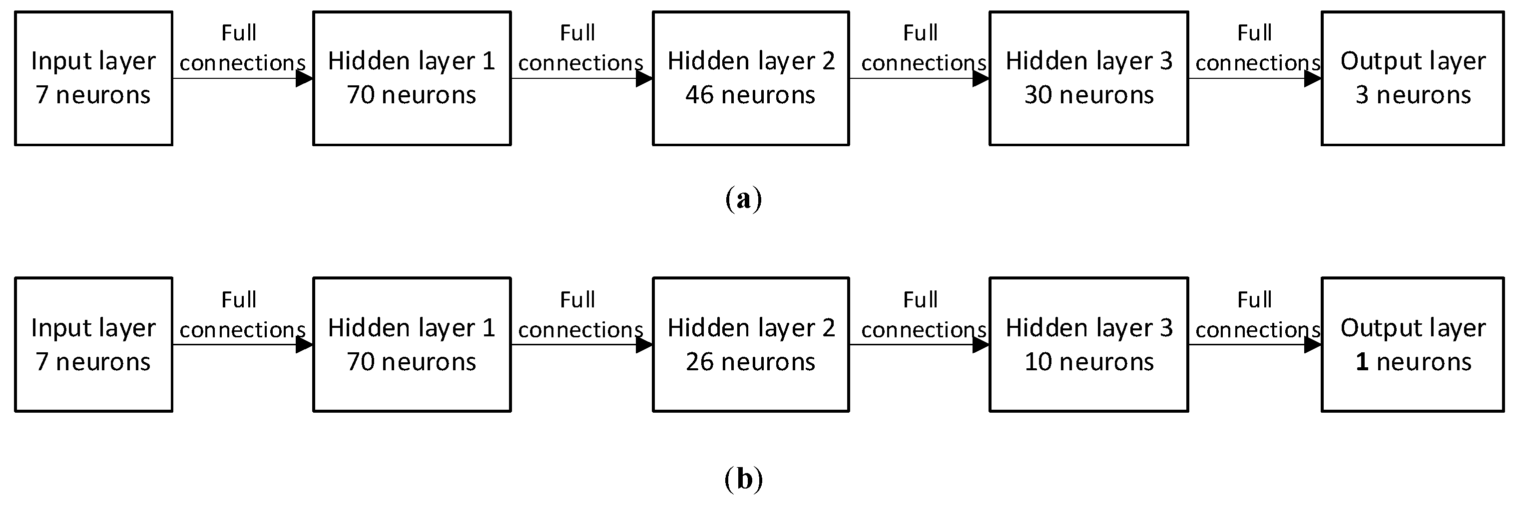
Using the multilayer neural network structure in [4], the policy strategy network consists of an input layer with n i = 7 neurons, an output layer with n o = 3 neurons, and three hidden layers of size h 1 = 10 n i , h 2 = h 1 h 3 , h 3 = 10 n o , as shown in Figure 4. The activation function of all hidden layers is the hyperbolic tangent. The critical network structure is the same as the policy network, except n o = 1 [23].
The actor is a policy network π θ ( a k | o k ) , where θ is the parameters of the policy network. The actor generates a control action based on the current state. The critic uses a multilayer neural network to estimate the value function and evaluate the performance of the action. The value function is the sum of the expected value of the sum of instantaneous reward R k along the trajectory episode with discount factor γ according to the strategy π θ , that is,
V k π θ ( x ) = 𝔼 τ ~ π θ [ i = k N 1 γ i k R i ( x i , a i ) | x i = x ]
Both the actor and the critic use a gradient method and small batches of samples to update network parameters θ .
The loss of the value network of the original actor–critic network is calculated as
A i π θ = i = k N 1 R i + γ V θ ( o i + 1 ) V θ ( o i )
A factor of the general advantage estimator (GAE) λ is added to obtain
A ^ i π θ = i = k N 1 ( γ λ ) i k ( R i + γ V θ ( o i + 1 ) V θ ( o i ) )
If the update step of the policy network is too large, which will lead to the nonconvergence of the network, the PPO algorithm adds a truncation term and obtains a truncation policy objective function J c l i p ( θ ) as
J c l i p ( θ ) = 1 N k = 0 N 1 min ( p k ( θ ) A k π θ o l d , c l i p ( p k ( θ ) , 1 κ , 1 + κ ) A k π θ o l d )
where the strategy probability ratio p k ( θ ) is calculated as
p k ( θ ) = π θ ( a k | o k ) π θ o l d ( a k | o k )
c l i p ( p k ( θ ) , 1 κ , 1 + κ ) = { 1 κ , 1 + κ , p k ( θ ) ,   p k ( θ ) < 1 κ p k ( θ ) > 1 + κ 1 κ < p k ( θ ) < 1 + κ
where κ is a small constant used to limit the learning speed. The function c l i p is constrained in the range of ( 1 κ , 1 + κ ) , so it indirectly limits the speed of policy update. Therefore, according to the above truncation strategy objective function, the strategy network parameters θ are updated according to the gradient direction
θ n e w = θ o l d + α θ θ J ( θ )
where α θ is the learning rate.
The implementation details and hyper parameters are shown in Table 1, which mainly refer to Ref. [23].

3. Flexible SaG Strategy

In the well-known optimal control problem (OCP) of rendezvous guidance, the number of orbital maneuvers is usually fixed, which is usually designed according to the overall goal of the mission [52]. This means that the solution of OCP for rendezvous guidance is dependent on the number of orbital maneuvers. Once the number of maneuvers changes, the OCP needs to be solved again. This inflexibility means additional computational burden and reduces real-time performance. Nevertheless, the close approach process is very dynamic, and the environment near the asteroid is highly unknown. We hope to overcome this inflexibility. To this end, we consider a SaG strategy.
The basic idea of the SaG strategy is to insert a certain number of SaG points into the original trajectory. At the SaG point, the spacecraft obtains the estimation of the current motion state according to the output of the navigation filter, and carries out the “stop” maneuver accordingly. The “stop” maneuver brakes the spacecraft’s velocity to zero, and the motion state just before the stop maneuver is saved. During the “stop” period, the navigation filter continues to work, and the additional “stop” maneuver is used to improve the range observability for AON. After “stopping” for a certain period of time, the spacecraft carries out the “go” maneuver to restore the spacecraft to the motion state before stopping. The navigation filter continues to work, and the additional “go” maneuver is used to improve the range observability again. Assuming that the “stop” time of the spacecraft is not long, other attributes of the mission will not be influenced. Then, the approach trajectory remains relatively unchanged in geometry after the SaG strategy is incorporated, but has a time delay. In this way, the SaG strategy can give some freedom to mission adaption.
Now we will formulate the SaG strategy. Let t s be the time of stop maneuver, x ^ t s = [ r ^ t s v ^ t s ] T be the spacecraft state output by navigation filter at time t s , where r ^ t s is the estimated position vector and v ^ t s is the estimated velocity vector. Then, the stop maneuver is Δ v s = v ^ t s , and the time between stop maneuver and go maneuver is Δ t s g . The time of go maneuver is t s + Δ t s g , and the go maneuver is Δ v g = v ^ t s .
Nevertheless, due to navigation error and maneuver error, the spacecraft has a certain residual velocity after the “stop” maneuver, as shown in Figure 5. Therefore, during the “stop” period, the residual motion of the spacecraft will cause a certain drift, as shown in Figure 5. The drift during the “stop” period will cause the subsequent trajectory to deviate from the original trajectory, and the deviation will continue to diverge through error propagation, as shown in Figure 6. It will eventually lead to a large deviation from the object terminal state. The drift is actually a challenge to the robustness of rendezvous trajectory or rendezvous guidance. It is hard for the deterministic method for solving the OCP of rendezvous guidance to overcome this problem.
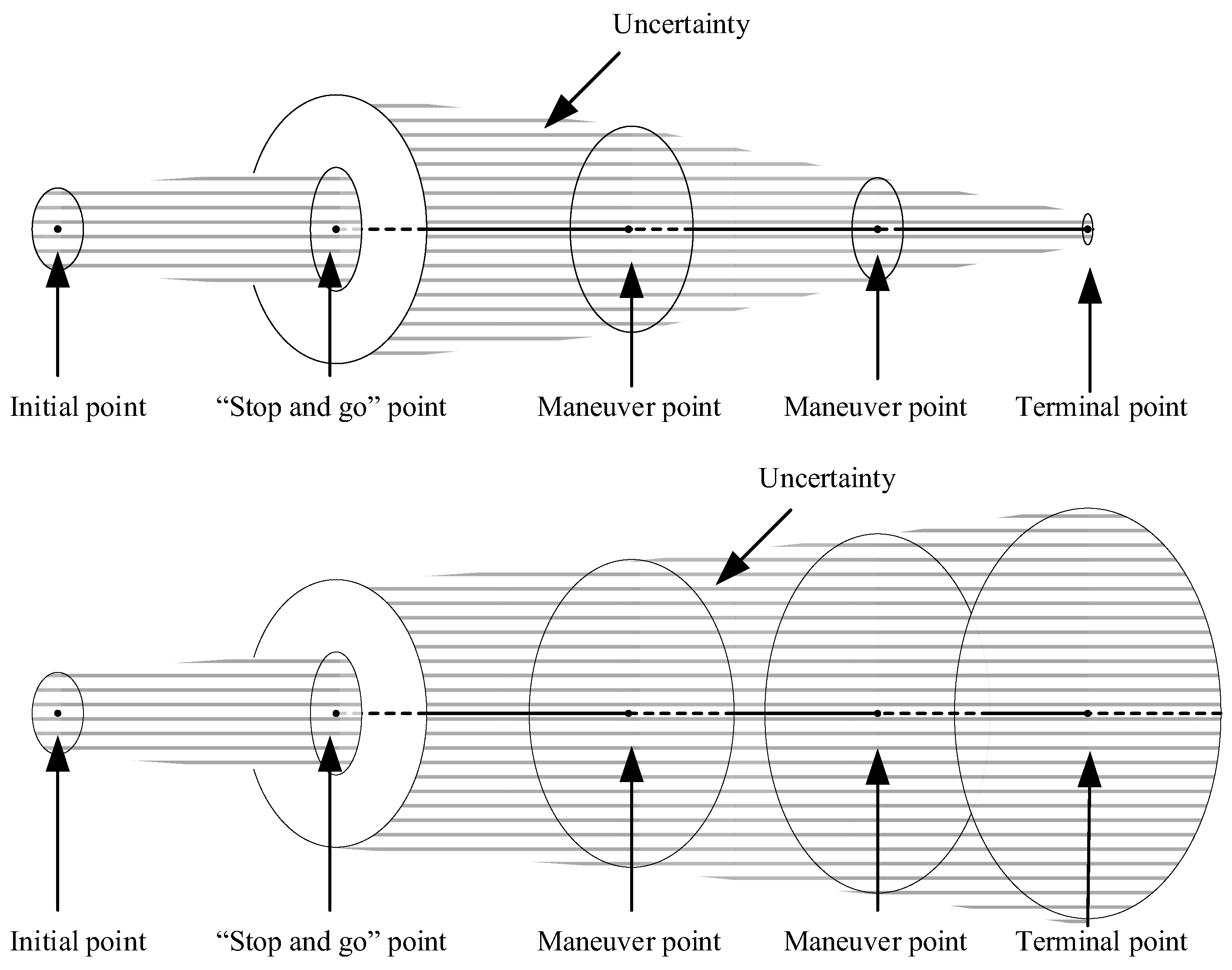
It is worth noting that the time delay and motion state drift caused by the SaG strategy can be well solved by a special design with the robust DRL-based guidance strategy. First, the input of the strategy network is a seven-dimensional vector composed of relative position, velocity, and left time. Therefore, it is only necessary to suspend the SaG strategy during the stop period, and then continue to execute the DRL-based guidance by inputting the output of the navigation filter into the strategy network, so that the whole process of navigation and guidance will be consistent. Second, as mentioned above, after the “stop” maneuver, the spacecraft does not actually stand still, but retains a small residual speed. Therefore, there will be a small residual motion during the SaG period, resulting in a certain spatial deviation between the starting state and the end state of the SaG period, as shown in Figure 6. Note that the spatial deviation will be small and bounded if there is a closed-loop station-keeping controller (such as the box control), general in asteroid missions [53], or the SaG period is small, and that the spatial deviation can be large if the station-keeping controller does not work and the SaG period is large. Nevertheless, the robustness of the DRL-based guidance will work in this situation. It can ensure the accuracy of terminal position and velocity state in the presence of initial motion state deviation. In this way, the SaG strategy can further improve the range observability. This also better explains the term “SaG point”, which means that in the framework of DRL-based robust guidance, the drift motion during the “stop” period can be ignored and can be regarded as a stationary point. We expect that when incorporating the SaG strategy, robust guidance will achieve better terminal accuracy than the open-loop guidance will do, as shown in Figure 7.
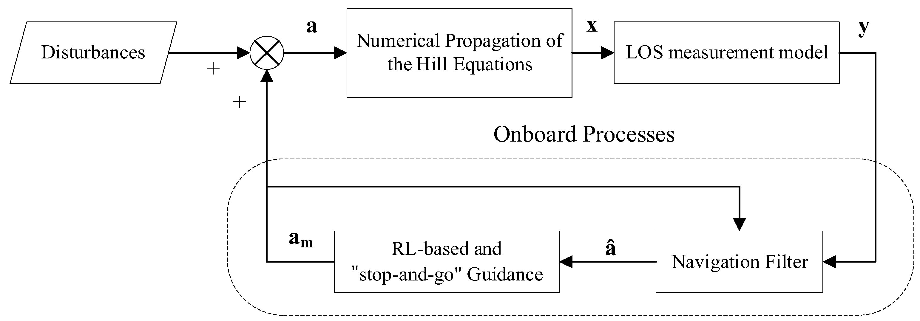
The number of SaG points is flexible. The SaG point can be triggered in different ways. For example, it can be triggered by the internal conditions of the navigation filter. For example, it can be triggered by the covariance matrix of the navigation filter to help accelerate the convergence. In addition, the SaG point can be triggered by an external trigger signal. Under the framework of online guidance, we propose an externally triggered SaG strategy, as shown in Figure 8. Figure 9 shows the online guidance framework obtained from AON and DRL-based guidance combined with the SaG strategy.

4. Numerical Simulation

4.1. Simulation Conditions

Taking 2016HO3 as the object asteroid (see Table 2 for its orbital elements), a simulation study of DRL-based guidance with the SaG strategy for the close approach was carried out. Note that although the mass of 2016HO3 is not small enough to ignore its gravity, we only use its orbit elements to demonstrate the proposed algorithm. In a typical R-bar approach scenario, it is planned to approach from r 0 = [ 10 , 000 0 0 ] m , v 0 = [ 0 0 0 ] m / s to r f = [ 1 , 000 / 2 1 , 000 / 2 0 ] k m , v f = [ 0 0 0 ] k m / s by 3 impulse maneuvers. The approach must be in the visibility cone with a cone half-angle β = 45 deg . The nominal total rendezvous time is 3 days. The SaG starts after 12 h and lasts for 3 h. The AON was used in this scenario. Table 3 summarizes the simulation parameters used. To verify the effectiveness of the proposed method, Monte Carlo simulation was conducted by introducing a specific level of perturbations. Each group of simulations consists of 200 realizations, and the statistics were analyzed.
The guidance and control strategy trained using DRL and SaG was evaluated through closed-loop simulation, which considers the uncertainty of the state navigation observation. In particular, the observation uncertainty of the navigation state was set to 1% of the relative range after navigation convergence. The RL model was trained under environments with no perturbation and with navigation errors. Correspondingly, the resulting control strategies are named π det e r m , π r o b u s t . The parameters for different uncertainty models corresponding to different control strategies are shown in Table 4.
The neural network was implemented using the Python and TensorFlow framework [54]. The PPO was implemented by stable baselines [55], an open-source library containing a set of improved implementations of RL algorithms. The network training using RL took approximately 26 h with 60 parallel workers on a computer equipped with two 10-core Intel Xeon Silver 4210R CPUs @2.40 GHz. It is worth noting that once the training is completed, the computational cost of closed-loop control simulation verification of the obtained control strategy can be ignored because only a few more matrix operations than the general relative orbit dynamics propagation remain.

4.2. AON Performance Improvement by SaG Strategy

First, we tested the potential of the SaG strategy to improve AON performance. The performance of AON is mainly represented by the convergence speed and the navigation accuracy. We conducted Monte Carlo simulation to compare AON performance before and after adding the SaG strategy. Monte Carlo simulation includes 200 implementations with randomly generated perturbations and noises (see Table 3), and statistical values are taken for analysis.
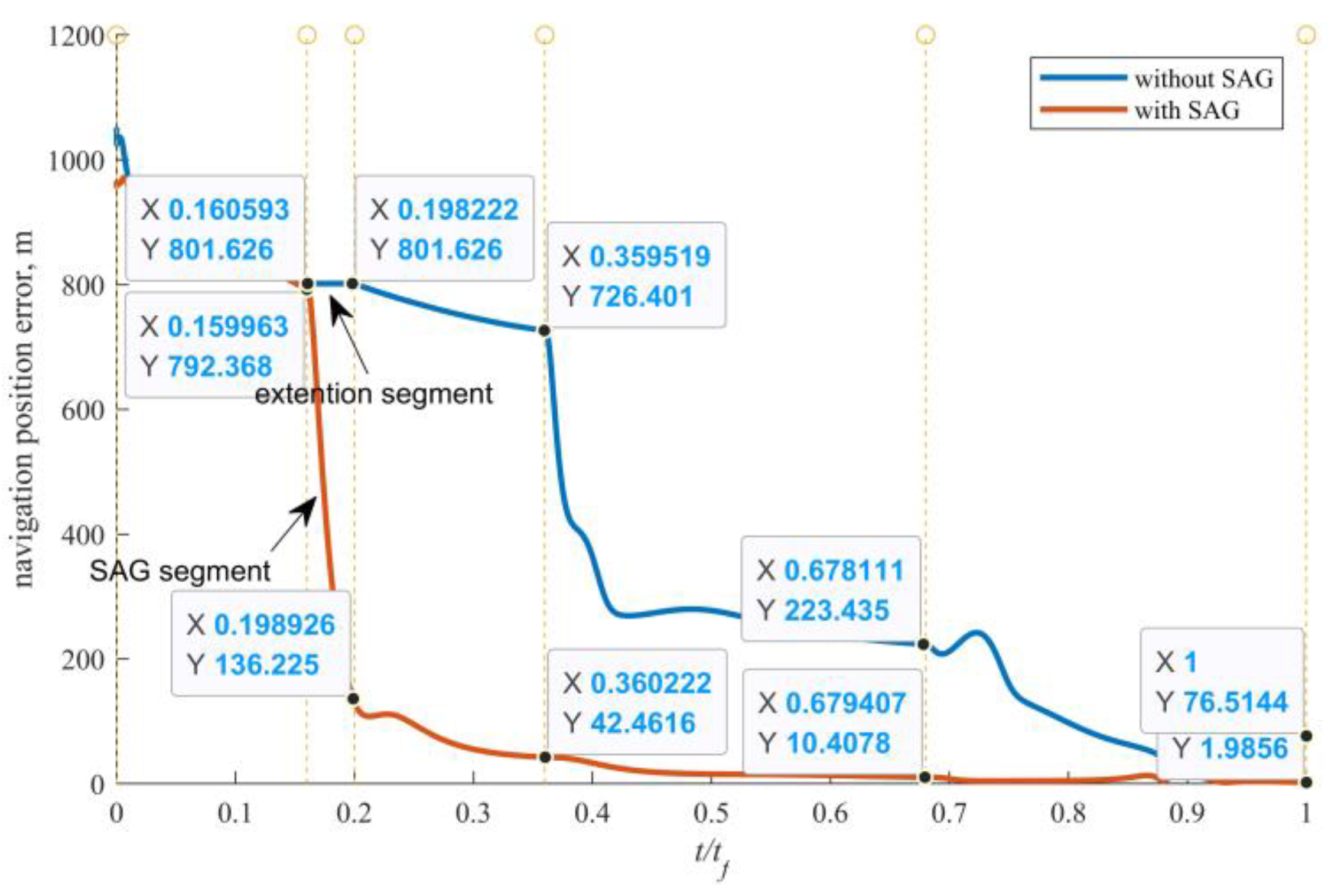
Figure 10 shows that after adding the SaG point, the convergence speed is greatly accelerated, and the convergence time is advanced from the original second maneuver time to the stop maneuver time. In addition, after the SaG point is added, the navigation accuracy after navigation convergence is also improved. Specifically, the terminal navigation position error is reduced from 76.5 m to 2 m, and from the >5% range to the <1% range, as shown in Figure 11. Figure 10 and Figure 11 also show that the navigation error drops rapidly during the SaG period. It is satisfactory for the rendezvous guidance to have the navigation error decrease to less than 1% as soon as possible. After adding the SaG point, the navigation error decreases to less than 1% after 0.3 t f , while the navigation error of the original guidance is always >1% range. Figure 12 shows the AON velocity error with and without SaG. It is seen that the AON velocity error without SaG never converges, but the AON velocity error with SaG converges after the SaG period. Specifically, the terminal navigation velocity error is reduced from 3 mm/s to <0.07 mm/s.

4.3. Deterministic Guidance Combined with SaG Strategy

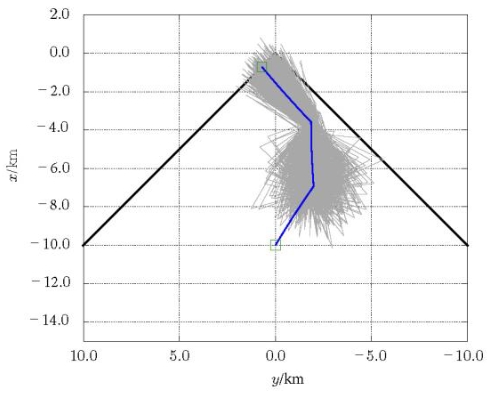
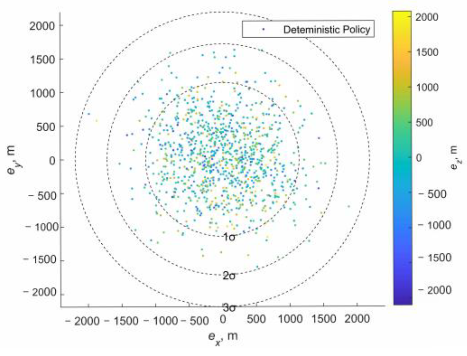
Deterministic guidance combined with the SaG strategy was simulated using the online guidance framework, as shown in Figure 9. The closed-loop simulation results of deterministic guidance with the SaG strategy are shown in Figure 13. The blue line represents the nominal trajectory of the deterministic policy π det e r m running on the unperturbed environment E n v u n p . The gray lines represent the Monte Carlo sample trajectories of π det e r m running on the observation uncertain environment E n v o b s . It can be seen that the nominal trajectory is a dog-leg one that can improve the range observability of AON. The characteristic of the nominal trajectory is shown in Table 5. It can be seen that the sample trajectories of π det e r m running on E n v o b s have a certain spatial deviation from the trajectory of π det e r m running on E n v u n p , especially at the SaG point, the deviation increases significantly. Specifically, the position deviation of the trajectory at the SaG point increased from 10 m to 1000 m, and the speed deviation increased from 1 mm/s to 5 mm/s. This is caused by the state estimation error of the navigation filter, which is also consistent with our expectations in Section 3 (see Figure 8). Subsequently, the deviation increases continuously through propagation, which greatly increases the terminal error of close approach rendezvous, as shown in Figure 14. Specifically, the terminal position error increased to 977.2 m.
This cannot meet the task requirements. This shows that although the SaG strategy can improve the AON performance, the state drift introduced by the residual speed during the “stop” period will erode the original deterministic guidance.

4.4. Robust Guidance Combined with SaG Strategy

Robust guidance combined with the SaG strategy was simulated also using the online guidance framework, as shown in Figure 9. The closed-loop simulation results of robust guidance with the SaG strategy are shown in Figure 15.
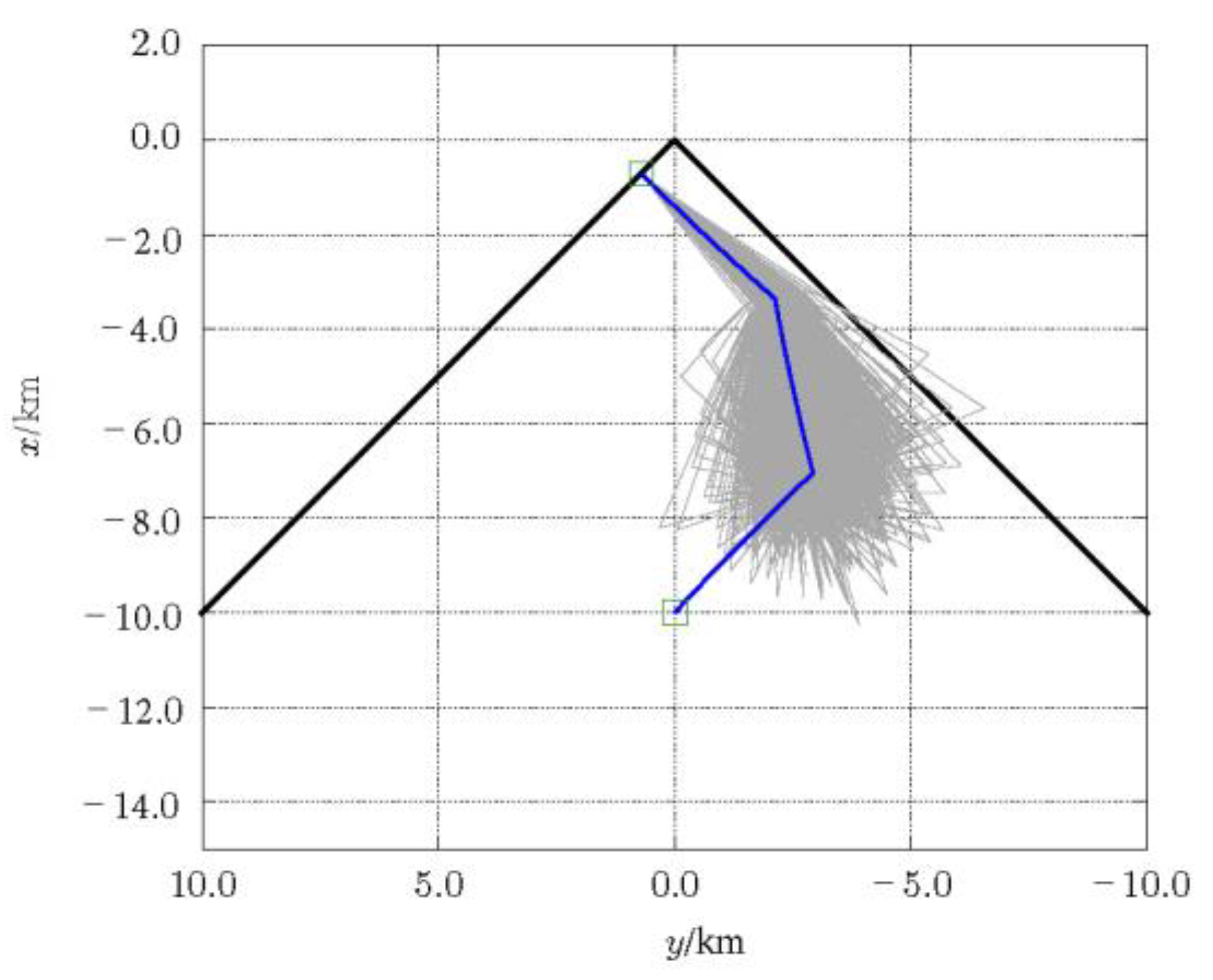
The blue line represents the nominal trajectory of the deterministic policy π r o b u s t running on the unperturbed environment E n v u n p . The gray lines represent the Monte Carlo sample trajectories of π r o b u s t running on the observation uncertain environment E n v o b s . It can be seen that the nominal trajectory is a dog-leg one that can improve the range observability of AON. The characteristic of the nominal trajectory is shown in Table 6. It can be seen that the sample trajectories of π det e r m running on E n v o b s have a certain spatial deviation from the trajectory of π det e r m running on E n v u n p , especially at the SaG point, the deviation increases significantly. Specifically, the position deviation of the trajectory at the SaG point increased from 10 m to 1000 m, and the speed deviation increased from 1 mm/s to 5 mm/s.
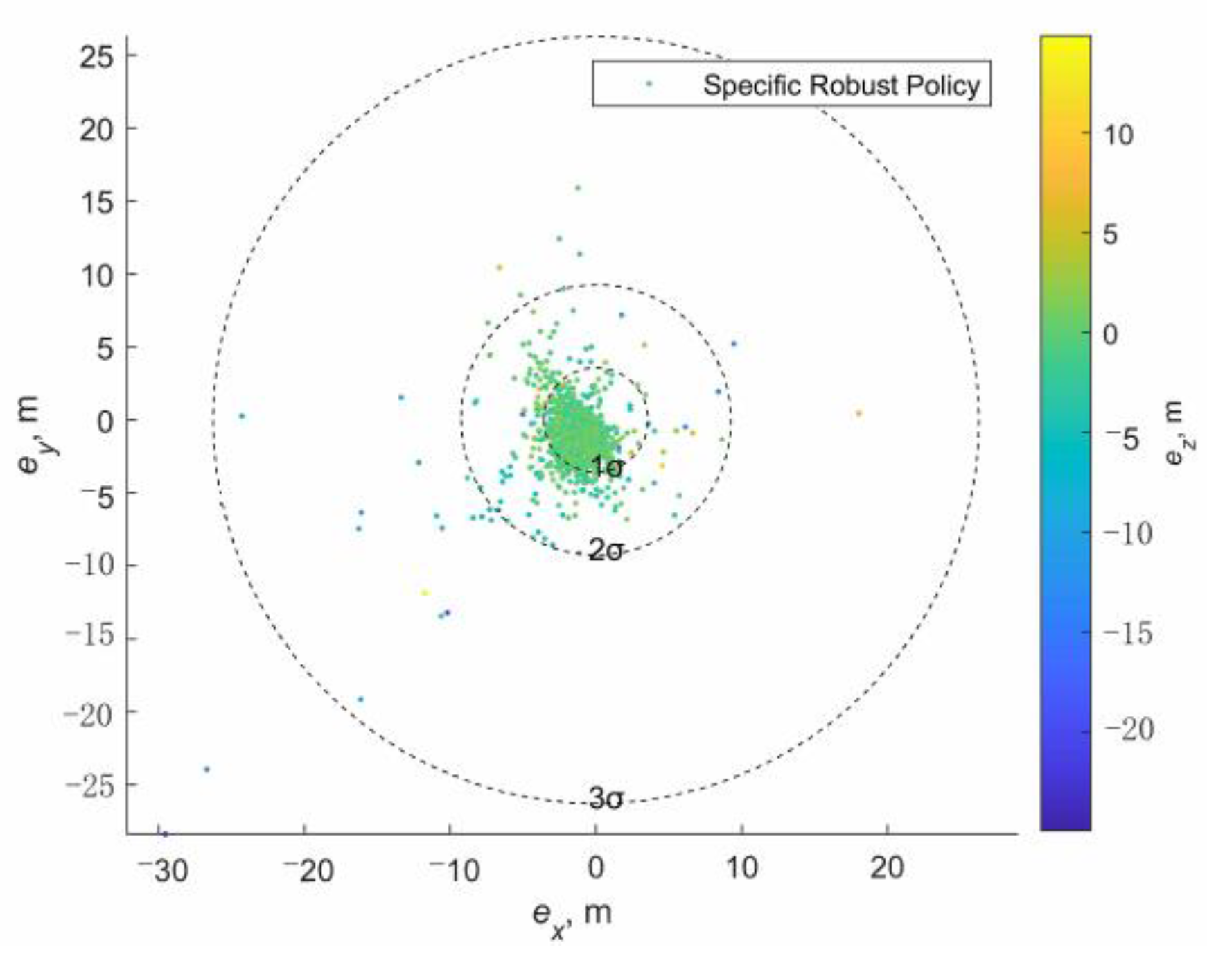
This is consistent with our expectations in Section 3 (see Figure 8). However, the subsequent development is quite different from Figure 13. The deviation decreases continuously through propagation, which greatly reduces the terminal error of close approach rendezvous, as shown in Figure 16. Specifically, the terminal position error was reduced to 3.578 m, as shown in Table 7.
Therefore, the robust guidance gradually absorbs the large trajectory deviation caused by the drift of the SaG point. This makes the terminal error of close approach rendezvous remain at a small level. This shows that the robust guidance strategy can be well compatible with the SaG strategy. It can not only improve the AON performance, but also absorb the state drift introduced by the residual speed during the “stop” period.
Through the combination of the SaG strategy and the robust guidance strategy based on DRL, the spacecraft can stop at any time in the process of approaching the asteroid, which gives the approach process more mission flexibility because stop time can be used for detection and debugging. The guidance need not be solved again, so the computational complexity is reduced. Because the onboard computing resources are very limited, this is very beneficial.

5. Conclusions

Aiming at the need for more adaptability and robustness during the asteroid close approach phase, a flexible and robust guidance framework based on DRL and SaG strategies is proposed in this paper. A good match between the SaG strategy and the DRL-based robust guidance is demonstrated. The SaG strategy will introduce a state drift, but the DRL-based guidance will absorb the state deviation to ensure a better terminal accuracy. The proposed framework has the ability to increase the number of orbital maneuvers while basically maintaining the geometry of the original trajectory. Such an ability to make temporary braking and then restart freely in the original rendezvous trajectory is very attractive. It makes the autonomous mission planning of the rendezvous process easier to realize. More accurate dynamics, including the gravity of the asteroid and the SRP, will be considered in future work.

Author Contributions

Conceptualization, H.Y. and D.L.; Investigation, H.Y.; Methodology, H.Y.; Validation, H.Y.; Writing—original draft, H.Y.; Writing—review & editing, D.L. All authors have read and agreed to the published version of the manuscript.

Funding

This work is supported by the National Natural Science Foundation of China (No. 11802335) and the National Natural Science Foundation of China (No. 11702321).

Institutional Review Board Statement

Not applicable.

Informed Consent Statement

Not applicable.

Data Availability Statement

Not applicable.

Conflicts of Interest

The authors declare no conflict of interest.

References

  1. Tsuda, Y.; Yoshikawa, M.; Abe, M.; Minamino, H.; Nakazawa, S. System design of the Hayabusa 2—Asteroid sample return mission to 1999 JU3. Acta Astronaut. 2013, 91, 356–362. [Google Scholar] [CrossRef]
  2. Gal-Edd, J.; Cheuvront, A. The OSIRIS-REx asteroid sample return mission. In Proceedings of the Aerospace Conference, Big Sky, MT, USA, 2–9 March 2013. [Google Scholar]
  3. Vetrisano, M.; Branco, J.; Cuartielles, J.; Yárnoz, D.; Vasile, M.L. Deflecting small asteroids using laser ablation: Deep space navigation and asteroid orbit control for LightTouch2 Mission. In Proceedings of the AIAA Guidance, Navigation & Control Conference, Boston, MA, USA, 19–22 August 2013. [Google Scholar]
  4. Gil-Fernandez, J.; Prieto-Llanos, T.; Cadenas-Gorgojo, R.; Graziano, M.; Drai, R. Autonomous GNC Algorithms for Rendezvous Missions to Near-Earth-Objects. In Proceedings of the Aiaa/Aas Astrodynamics Specialist Conference & Exhibit, Honolulu, HI, USA, 18–21 August 2008. [Google Scholar]
  5. Ogawa, N.; Terui, F.; Mimasu, Y.; Yoshikawa, K.; Tsuda, Y. Image-based autonomous navigation of Hayabusa2 using artificial landmarks: The design and brief in-flight results of the first landing on asteroid Ryugu. Astrodynamics 2020, 4, 15. [Google Scholar] [CrossRef]
  6. Ono, G.; Terui, F.; Ogawa, N.; Mimasu, Y.; Yoshikawa, K.; Takei, Y.; Saiki, T.; Tsuda, Y. Design and flight results of GNC systems in Hayabusa2 descent operations. Astrodynamics 2020, 4, 105–117. [Google Scholar] [CrossRef]
  7. Kominato, T.; Matsuoka, M.; Uo, M.; Hashimoto, T.; Kawaguchi, J.I. Optical hybrid navigation and station keeping around Itokawa. In Proceedings of the AIAA/AAS Astrodynamics Specialist Conference and Exhibit, Keystone, CO, USA, 18–21 August 2006; p. 6535. [Google Scholar]
  8. Tsuda, Y.; Takeuchi, H.; Ogawa, N.; Ono, G.; Kikuchi, S.; Oki, Y.; Ishiguro, M.; Kuroda, D.; Urakawa, S.; Okumura, S.-I. Rendezvous to asteroid with highly uncertain ephemeris: Hayabusa2’s Ryugu-approach operation result. Astrodynamics 2020, 4, 137–147. [Google Scholar] [CrossRef]
  9. Greco, C.; Carlo, M.; Vasile, M.; Epenoy, R. Direct Multiple Shooting Transcription with Polynomial Algebra for Optimal Control Problems Under Uncertainty. Astronaut. Acta 2019, 170, 224–234. [Google Scholar] [CrossRef]
  10. Greco, C.; Vasile, M. Closing the Loop Between Mission Design and Navigation Analysis. In Proceedings of the 71th International Astronautical Congress (IAC 2020)—The CyberSpace Edition, Virtual, 12–14 October 2020. [Google Scholar]
  11. Ozaki, N.; Campagnola, S.; Funase, R.; Yam, C.H. Stochastic Differential Dynamic Programming with Unscented Transform for Low-Thrust Trajectory Design. J. Guid. Control Dyn. 2017, 41, 377–387. [Google Scholar] [CrossRef]
  12. Ozaki, N.; Campagnola, S.; Funase, R. Tube Stochastic Optimal Control for Nonlinear Constrained Trajectory Optimization Problems. J. Guid. Control Dyn. 2020, 43, 1–11. [Google Scholar] [CrossRef]
  13. Oguri, K.; Mcmahon, J.W. Risk-aware Trajectory Design with Impulsive Maneuvers: Convex Optimization Approach. In Proceedings of the AAS/AIAA Astrodynamics Specialist Conference, Portland, ME, USA, 11–15 August 2019. [Google Scholar]
  14. Oguri, K.; Mcmahon, J.W. Risk-aware Trajectory Design with Continuous Thrust: Primer Vector Theory Approach. In Proceedings of the AAS/AIAA Astrodynamics Specialist Conference, Portland, ME, USA, 11–15 August 2019. [Google Scholar]
  15. Carlo, M.; Vasile, M.; Greco, C.; Epenoy, R. Robust Optimisation of Low-thrust Interplanetary Transfers using Evidence Theory. In Proceedings of the 29th AAS/AIAA Space Flight Mechanics Meeting, Ka’anapali, HI, USA, 13–17 January 2019. [Google Scholar]
  16. Izzo, D.; Mrtens, M.; Pan, B. A survey on artificial intelligence trends in spacecraft guidance dynamics and control. Astrodynamics 2019, 3, 287–299. [Google Scholar] [CrossRef]
  17. Izzo, D.; Sprague, C.; Tailor, D. Machine learning and evolutionary techniques in interplanetary trajectory design. In Modeling and Optimization in Space Engineering; Springer: Cham, Switzerland, 2018. [Google Scholar]
  18. Sutton, R.; Barto, A. Reinforcement Learning: An Introduction, 2nd ed.; MIT Press: Cambridge, MA, USA, 2018. [Google Scholar]
  19. Lillicrap, T.P.; Hunt, J.J.; Pritzel, A.; Heess, N.; Erez, T.; Tassa, Y.; Silver, D.; Wierstra, D. Continuous control with deep reinforcement learning. arXiv 2015, arXiv:1509.02971. [Google Scholar]
  20. Mnih, V.; Badia, A.P.; Mirza, M.; Graves, A.; Kavukcuoglu, K. Asynchronous Methods for Deep Reinforcement Learning. arXiv 2016, arXiv:1602.01783. [Google Scholar]
  21. Schulman, J.; Wolski, F.; Dhariwal, P.; Radford, A.; Klimov, O. Proximal Policy Optimization Algorithms. arXiv 2017, arXiv:1707.06347. [Google Scholar]
  22. Holt, H.; Armellin, R.; Scorsoglio, A.; Furfaro, R. Low-Thrust Trajectory Design Using Closed-Loop Feedback-Driven Control Laws and State-Dependent Parameters. In Proceedings of the AIAA Scitech 2020 Forum, Orlando, FL, USA, 6–10 January 2020. [Google Scholar]
  23. Zavoli, A.; Federici, L. Reinforcement Learning for Robust Trajectory Design of Interplanetary Missions. J. Guid. Control Dyn. 2021, 44, 1440–1453. [Google Scholar] [CrossRef]
  24. Arora, L.; Dutta, A. Reinforcement Learning for Sequential Low-Thrust Orbit Raising Problem. In Proceedings of the AIAA Scitech 2020 Forum, Orlando, FL, USA, 6–10 January 2020. [Google Scholar]
  25. Lafarge, N.B.; Miller, D.; Howell, K.C.; Linares, R. Guidance for Closed-Loop Transfers using Reinforcement Learning with Application to Libration Point Orbits. In Proceedings of the AIAA Scitech 2020 Forum, Orlando, FL, USA, 6–10 January 2020. [Google Scholar]
  26. Miller, D.; Englander, J.; Linares, R. Interplanetary Low-Thrust Design Using Proximal Policy Optimization. In Proceedings of the AAS 19-779, Portland, ME, USA, 11–15 August 2019. [Google Scholar]
  27. Silvestrini, S.; Lavagna, M.R. Spacecraft Formation Relative Trajectories Identification for Collision-Free Maneuvers using Neural-Reconstructed Dynamics. In Proceedings of the AIAA Scitech 2020 Forum, Orlando, FL, USA, 6–10 January 2020. [Google Scholar]
  28. Scorsoglio, A.; Furfaro, R.; Linares, R.; Massari, M. Actor-Critic Reinforcement Learning Approach to Relative Motion Guidance in Near-Rectilinear Orbit. In Proceedings of the 29th AAS/AIAA Space Flight Mechanics Meeting, Ka’anapali, HI, USA, 13–17 January 2019. [Google Scholar]
  29. Gaudet, B.; Linares, R.; Furfaro, R. Terminal Adaptive Guidance via Reinforcement Meta-Learning: Applications to Autonomous Asteroid Close-Proximity Operations. Acta Astronaut. 2020, 171, 1–13. [Google Scholar] [CrossRef] [Green Version]
  30. Liu, Z.; Wang, J.; He, S.; Shin, H.-S.; Tsourdos, A. Learning prediction-correction guidance for impact time control. Aerosp. Sci. Technol. 2021, 119, 107187. [Google Scholar] [CrossRef]
  31. Federici, L.; Benedikter, B.; Zavoli, A. Deep Learning Techniques for Autonomous Spacecraft Guidance During Proximity Operations. J. Spacecr. Rocket. 2021, 58, 1774–1785. [Google Scholar] [CrossRef]
  32. Federici, L.; Scorsoglio, A.; Ghilardi, L.; D’Ambrosio, A.; Benedikter, B.; Zavoli, A.; Furfaro, R. Image-based Meta-Reinforcement Learning for Autonomous Terminal Guidance of an Impactor in a Binary Asteroid System. In Proceedings of the AIAA SCITECH 2022 Forum, San Diego, CA, USA, 3–7 January 2022. [Google Scholar]
  33. Hovell, K.; Ulrich, S. Deep Reinforcement Learning for Spacecraft Proximity Operations Guidance. J. Spacecr. Rocket. 2021, 58, 254–264. [Google Scholar] [CrossRef]
  34. Gaudet, B.; Furfaro, R. Robust Spacecraft Hovering Near Small Bodies in Environments with Unknown Dynamics Using Reinforcement Learning. In Proceedings of the AIAA/AAS Astrodynamics Specialist Conference, Minneapolis, MI, USA, 13–16 August 2012. [Google Scholar]
  35. Willis, S.; Izzo, D.; Hennes, D. Reinforcement Learning for Spacecraft Maneuvering Near Small Bodies. In Proceedings of the AAS/AIAA Space Flight Mechanics Meeting, Napa, CA, USA, 14–18 February 2016. [Google Scholar]
  36. Furfaro, R.; Linares, R. Waypoint-Based generalized ZEM/ZEV feedback guidance for planetary landing via a reinforcement learning approach. In Proceedings of the 3rd International Academy of Astronautics Conference on Dynamics and Control of Space Systems, DyCoSS, Moscow, Russia, 30 May–1 June 2017. [Google Scholar]
  37. Gaudet, B.; Furfaro, R.; Linares, R. Reinforcement learning for angle-only intercept guidance of maneuvering targets. Aerosp. Sci. Technol. 2019, 99, 105746. [Google Scholar] [CrossRef]
  38. Furfaro, R.; Scorsoglio, A.; Linares, R.; Massari, M. Adaptive generalized ZEM-ZEV feedback guidance for planetary landing via a deep reinforcement learning approach. Acta Astronaut. 2020, 171, 156–171. [Google Scholar] [CrossRef]
  39. Scorsoglio, A.; D’Ambrosio, A.; Ghilardi, L.; Furfaro, R.; Curti, F. Safe lunar landing via images: A reinforcement meta-learning application to autonomous hazard avoidance and landing. In Proceedings of the 2020 AAS/AIAA Astrodynamics Specialist Conference—Lake Tahoe, Virtual, 9–12 August 2020. [Google Scholar]
  40. Scorsoglio, A.; Andrea, D.; Ghilardi, L.; Gaudet, B. Image-based Deep Reinforcement Meta-Learning for Autonomous Lunar Landing. J. Spacecr. Rocket. 2021, 59, 153–165. [Google Scholar] [CrossRef]
  41. Jiang, X.; Li, S.; Furfaro, R. Integrated guidance for Mars entry and powered descent using reinforcement learning and pseudospectral method. Acta Astronaut. 2019, 163, 114–129. [Google Scholar] [CrossRef]
  42. Gaudet, B.; Linares, R.; Furfaro, R. Adaptive Guidance and Integrated Navigation with Reinforcement Meta-Learning. Acta Astronaut. 2019, 169, 180–190. [Google Scholar] [CrossRef]
  43. Gaudet, B.; Furfaro, R.; Linares, R. A Guidance Law for Terminal Phase Exo-Atmospheric Interception Against a Maneuvering Target using Angle-Only Measurements Optimized using Reinforcement Meta-Learning. In Proceedings of the AIAA Scitech 2020 Forum, Orlando, FL, USA, 6–10 January 2020. [Google Scholar]
  44. D’Amico, S.; Ardaens, J.S.; Gaias, G.; Benninghoff, H.; Schlepp, B.; Jorgensen, J.L. Noncooperative Rendezvous Using Angles-Only Optical Navigation: System Design and Flight Results. J. Guid. Control Dyn. 2013, 36, 1576–1595. [Google Scholar] [CrossRef]
  45. Grzymisch, J.; Fichter, W. Optimal Rendezvous Guidance with Enhanced Bearings-Only Observability. J. Guid. Control Dyn. 2015, 38, 1131–1140. [Google Scholar] [CrossRef]
  46. Mok, S.-H.; Pi, J.; Bang, H. One-step rendezvous guidance for improving observability in bearings-only navigation. Adv. Space Res. 2020, 66, 2689–2702. [Google Scholar] [CrossRef]
  47. Hou, B.; Wang, D.; Wang, J.; Ge, D.; Zhou, H.; Zhou, X. Optimal Maneuvering for Autonomous Relative Navigation Using Monocular Camera Sequential Images. J. Guid. Control Dyn. 2021, 44, 1947–1960. [Google Scholar] [CrossRef]
  48. Hartley, E.N.; Trodden, P.A.; Richards, A.G.; Maciejowski, J.M. Model predictive control system design and implementation for spacecraft rendezvous. Control Eng. Pract. 2012, 20, 695–713. [Google Scholar] [CrossRef]
  49. Hartley, E. A tutorial on model predictive control for spacecraft rendezvous. In Proceedings of the Control Conference, Linz, Austria, 15–17 July 2015. [Google Scholar]
  50. Vasile, M.; Maddock, C.A. Design of a Formation of Solar Pumped Lasers for Asteroid Deflection. Adv. Space Res. 2012, 50, 891–905. [Google Scholar] [CrossRef]
  51. Okasha, M.; Newman, B. Guidance, Navigation and Control for Satellite Proximity Operations using Tschauner-Hempel Equations. J. Astronaut. Sci. 2013, 60, 109–136. [Google Scholar] [CrossRef]
  52. Yuan, H.; Li, D.; Wang, J. Hybrid Guidance Optimization for Multipulse Glideslope Approach with Bearing-Only Navigation. Aerospace 2022, 9, 242. [Google Scholar] [CrossRef]
  53. Bhaskaran, S.; Nandi, S.; Broschart, S.; Wallace, M.; Cangahuala, L.A.; Olson, C. Small Body Landings Using Autonomous Onboard Optical Navigation. J. Astronaut. Sci. 2013, 58, 409–427. [Google Scholar] [CrossRef]
  54. Abadi, M.; Barham, P.; Chen, J.; Chen, Z.; Zhang, X. TensorFlow: A system for large-scale machine learning. USENIX Assoc. 2016, 16, 265–283. [Google Scholar]
  55. Hill, A.; Raffin, A.; Ernestus, M.; Gleave, A.; Kanervisto, A.; Traore, R.; Dhariwal, P.; Hesse, C.; Klimov, O.; Nichol, A.; et al. Stable Baselines. GitHub Repos. Available online: https://github.com/hill-a/stable-baselines (accessed on 5 May 2018).
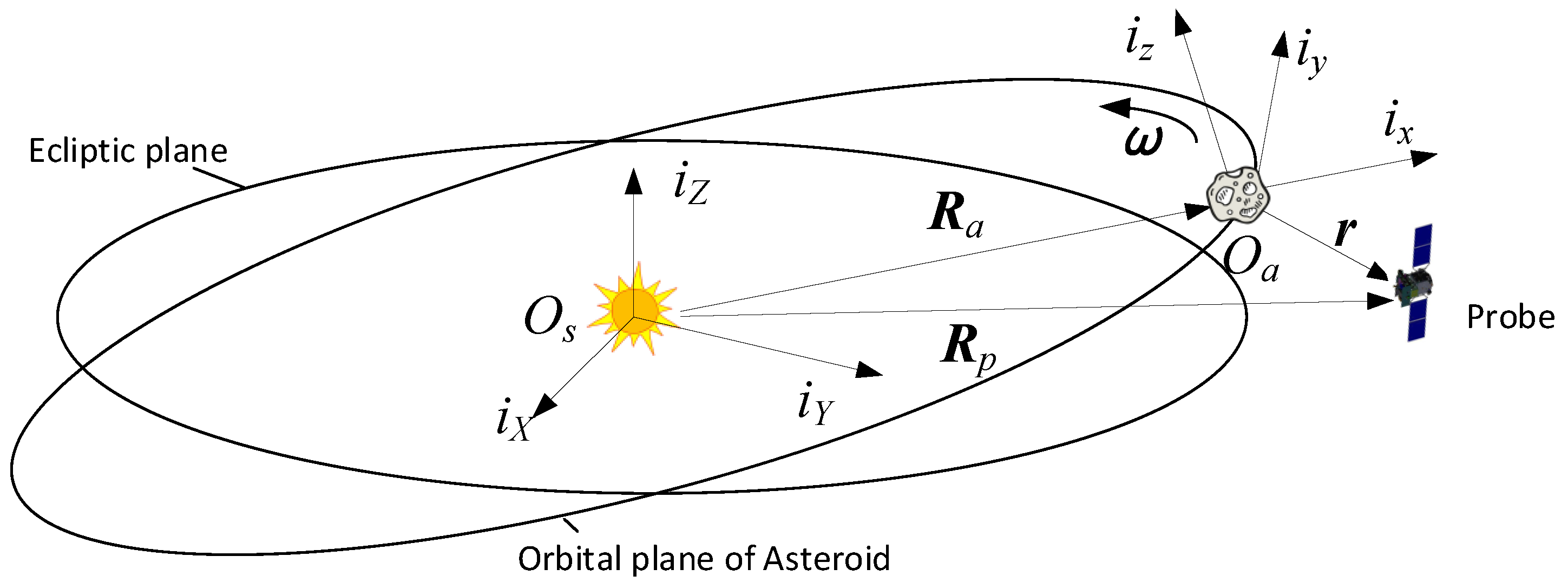
Figure 1. Definition of asteroid Hill rotation coordinate systems.
Aerospace 09 00569 g001
Figure 2. Visibility cone with a cone half-angle of β.
Aerospace 09 00569 g002
Figure 3. A typical actor–critic structure of PPO.
Aerospace 09 00569 g003
Figure 4. Actor–critic network structure. (a) Structure of policy network; (b) structure of critic network.
Aerospace 09 00569 g004
Figure 5. During the “stop” period, the residual motion of the spacecraft will cause a certain drift.
Aerospace 09 00569 g005
Figure 6. The drift during “stop” period will cause the subsequent trajectory to deviate from the original trajectory, and this deviation will continue to diverge through error propagation.
Aerospace 09 00569 g006
Figure 7. Expected results: the figure above is robust guidance, and the figure below is open-loop guidance.
Aerospace 09 00569 g007
Figure 8. DRL-based guidance combined with SaG strategy: determine whether to insert SaG point at a certain time or at a certain point of the original trajectory according to the external trigger signal.
Aerospace 09 00569 g008
Figure 9. Onboard guidance simulation model.
Aerospace 09 00569 g009
Figure 10. AON position error with and without SaG.
Aerospace 09 00569 g010
Figure 11. AON position error (%range) with and without SaG.
Aerospace 09 00569 g011
Figure 12. AON velocity error with and without SaG.
Aerospace 09 00569 g012
Figure 13. Deterministic guidance with the SaG strategy case: the Monte Carlo sample trajectories have a large spatial deviation from the nominal trajectory.
Aerospace 09 00569 g013
Figure 14. Distribution of the terminal position errors with deterministic guidance and the SaG strategy.
Aerospace 09 00569 g014
Figure 15. Robust guidance with the SaG strategy case: the Monte Carlo sample trajectories have a spatial deviation from the nominal trajectory and the robust guidance gradually absorbs the large trajectory deviation caused by the drift of the SaG point.
Aerospace 09 00569 g015
Figure 16. Distribution of the terminal position errors with robust guidance and the SaG strategy.
Aerospace 09 00569 g016
Table 1. Super parameters of the PPO algorithm.
Super ParameterSymbolValue
Discount factor γ 0.9999
GAE factor λ 0.99
Learning rate α θ 2.5 × 10⁻⁴
Clip range κ 0.3
Training step T 200 × 106
Parallel workers n p 60
Episodes per batch n b 4
SGA epochs per update n e 30
Table 2. Orbit elements of 2016HO3.
Epoch 2459600.5 (21 January 2022.0) TDB
Reference: Heliocentric J2000 Ecliptic
ElementValueUnits
Semimajor axis1.001137344063433AU
Eccentricity0.1029843787386461
Inclination7.788928644671124deg
Longitude of the ascending node66.0142959682462deg
Perihelion argument angle305.6646720090911deg
Mean anomaly107.172338605596deg
Table 3. Simulation parameters.
ParameterValueUnit
Environment
Equivalent disturbance, 1σ1 × 10⁻⁷m/s2
Measurement Noise, 1σ1mrad
Sample time10s
Rendezvous Mission
Initial condition, x 0 = [ x , y , z , x ˙ , y ˙ , z ˙ ] [ 10000 , 0 , 0 , 0 , 0 , 0 ] m m m
m/s m/s m/s
Target condition, x f = [ x , y , z , x ˙ , y ˙ , z ˙ ] [ 1000 / 2 , 1000 / 2 , 0 , 0 , 0 , 0 ] m m m
m/s m/s m/s
Number of pulses, N3
Total time, T3day
Planned maneuver interval time, τ 12hour
Start time of SaG 12hour
Duration of SaG3hour
Navigation Initiation
Initial navigation error, 1σ [ 1000 , 1000 , 1000 , 1 , 1 , 1 ] m m m
mm/s mm/s mm/s
Table 4. Different control strategies and different environments.
Policy NameEnvironment NameObservation Uncertainty
π det e r m E n v u n p 0
0
π r o b u s t E n v o b s 1% range
5 mm/s
Table 5. The characteristic of the nominal trajectory for π det e r m .
Time Step Maneuver   Δ V , m / s Observation   Angle   θ , deg
00.02218.35
10.01518.48
20.017121.21
30.023-
Table 6. The characteristic of the nominal trajectory for π r o b u s t .
Time Step Maneuver   Δ V , m / s Observation   Angle   θ , deg
00.02625.78
10.02721.67
20.015138.12
30.024-
Table 7. Terminal accuracy of different policies.
Policy NameEnvironment Fuel   Cost   Δ V , m / s Terminal   Errors   Δ r , m
MeanStdMeanStd
π det e r m E n v u n p 0.07780-11.51-
E n v o b s 0.08250.0072977.2406.8
π r o b u s t E n v u n p 0.09175-2.123-
E n v o b s 0.09430.00463.5783.436
Publisher’s Note: MDPI stays neutral with regard to jurisdictional claims in published maps and institutional affiliations.