
Aerodynamic Characteristics of Bristled Wings in Flapping Flight


Abstract
:1. Introduction
2. Materials and Methods
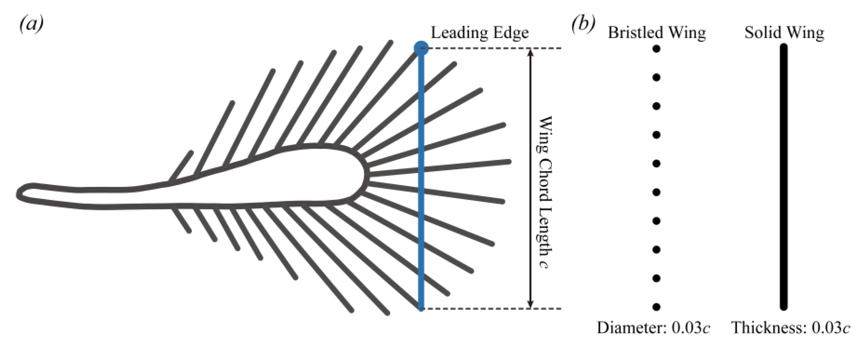
2.1. Research Subject and Morphology Measurement
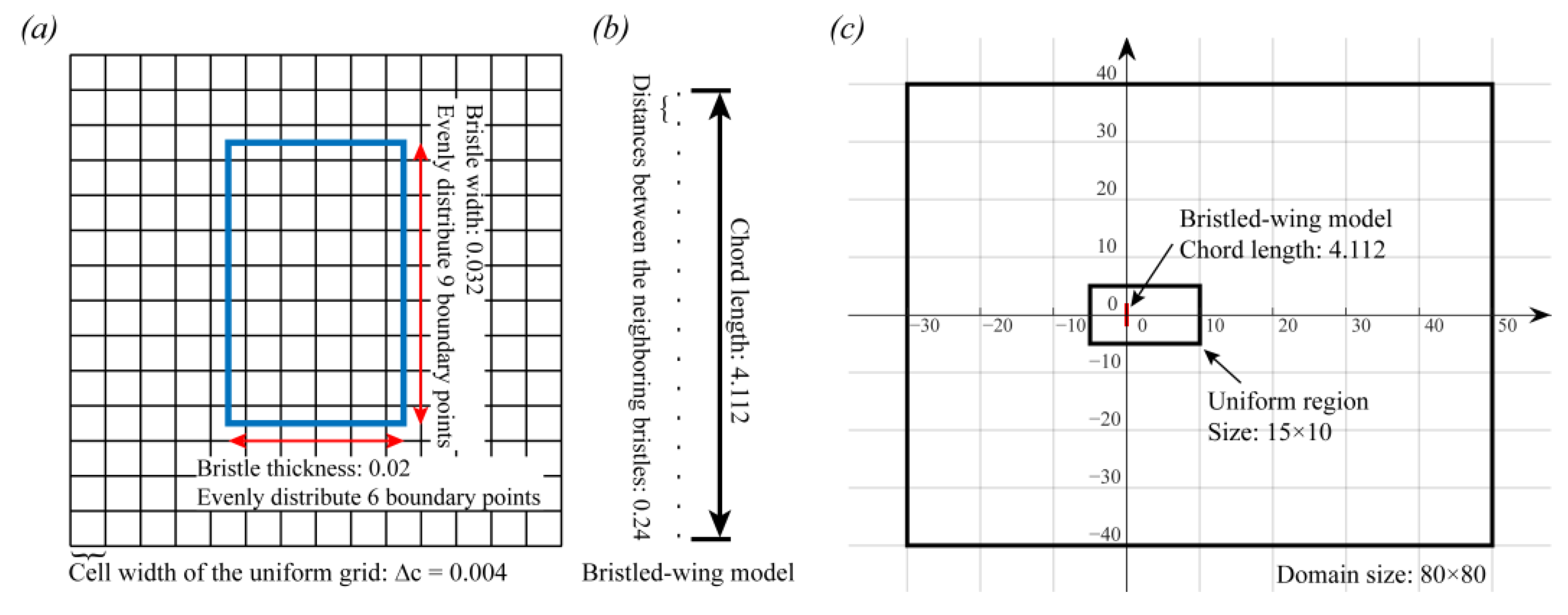
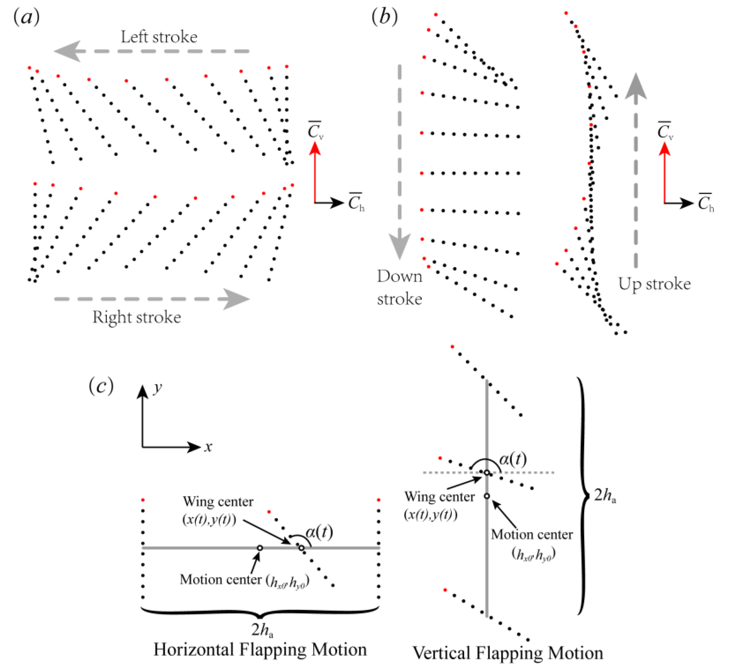
2.2. Bristled Wing Model and Kinematics
2.3. Methodology
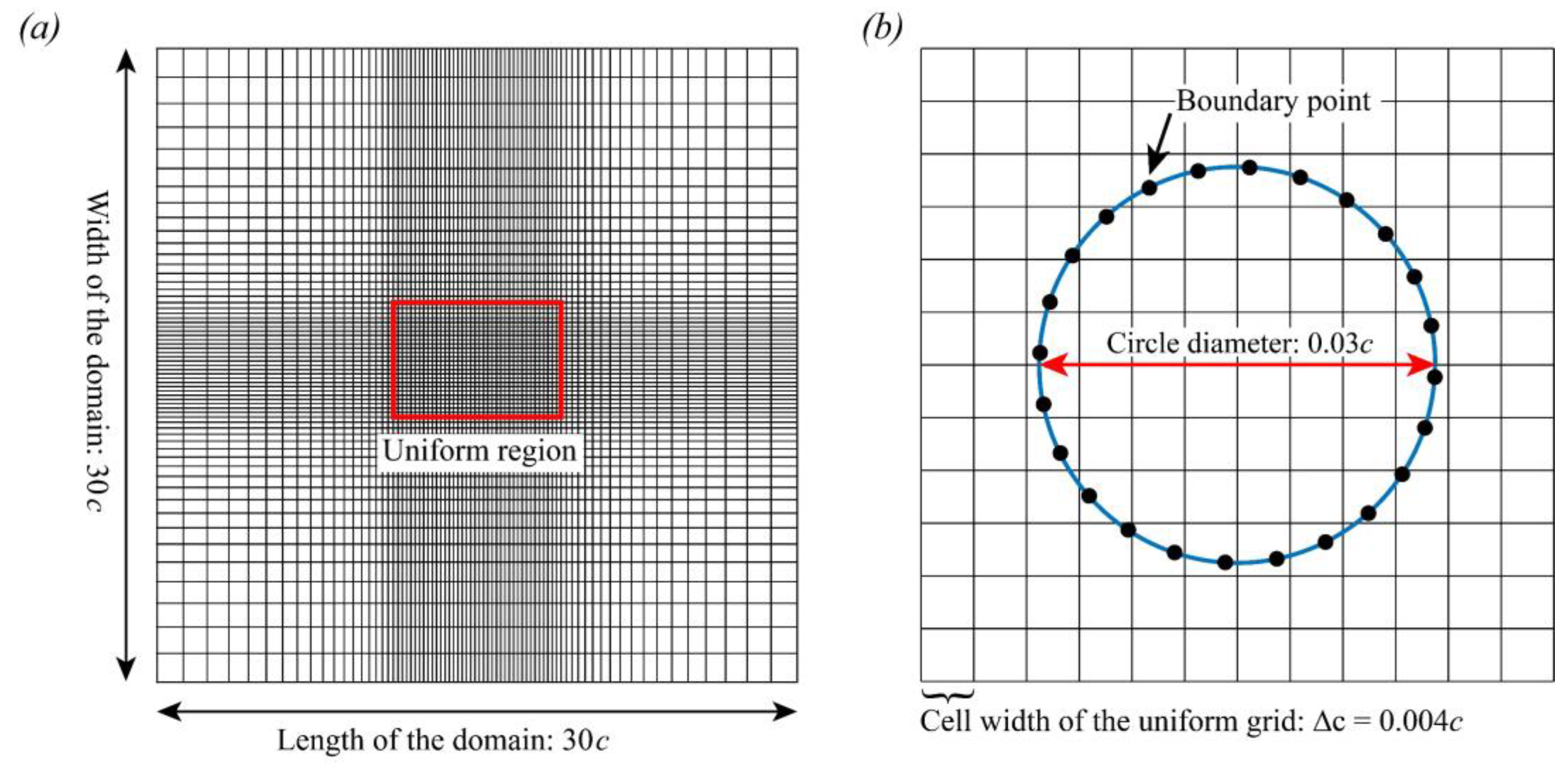
2.3.1. Immersed Boundary Method
2.3.2. Aerodynamic Force, Power, and Efficiency in Flapping Flight
3. Results and Discussion
3.1. Lift-Based and Drag-Based Flapping of the Bristled Wing
3.1.1. The Instantaneous Force Production of the Bristled Wing in HF and VF Motion
3.1.2. Air Leakage and the Effect of Re
3.1.3. Comparison between Bristled Wing and Solid Wing in HF and VF Motion
3.2. Wing–Wing Interactions of the Bristled Wing
3.2.1. Augmentation of the Bristled Wing in Clap-And-Fling
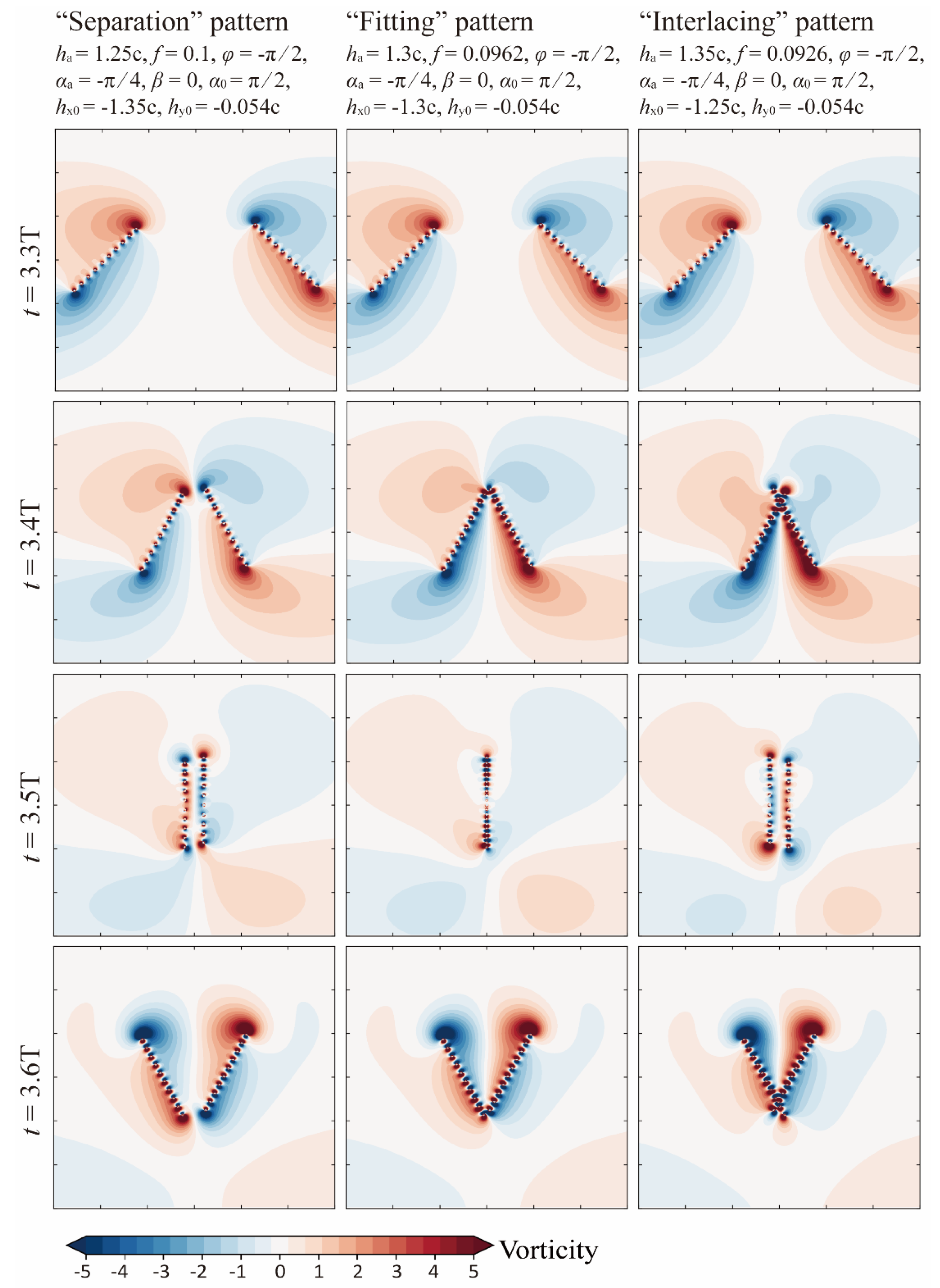
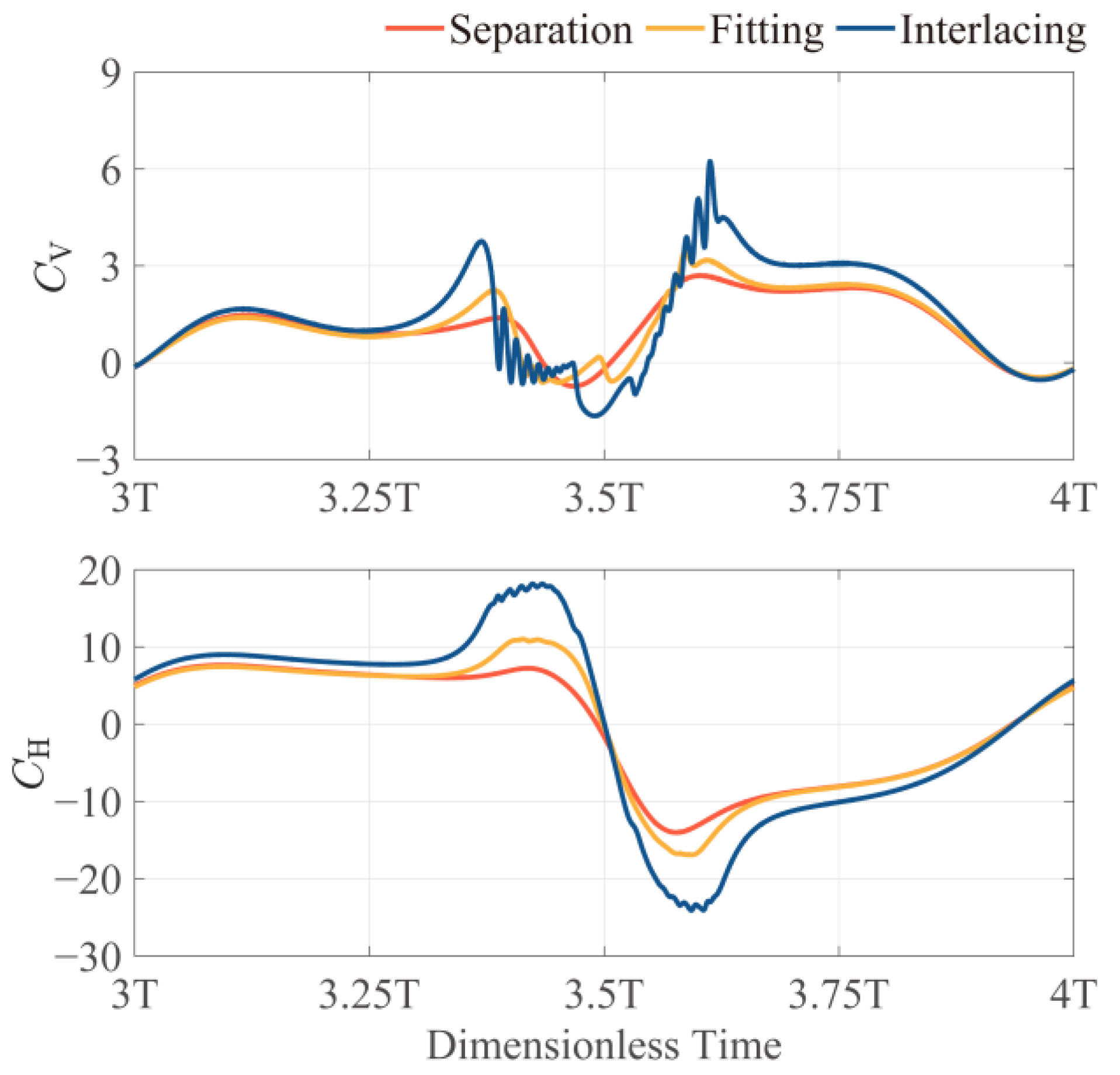
3.2.2. Effect of Bristle Crossing and Inter-Wing Gap Reduction
4. Conclusions
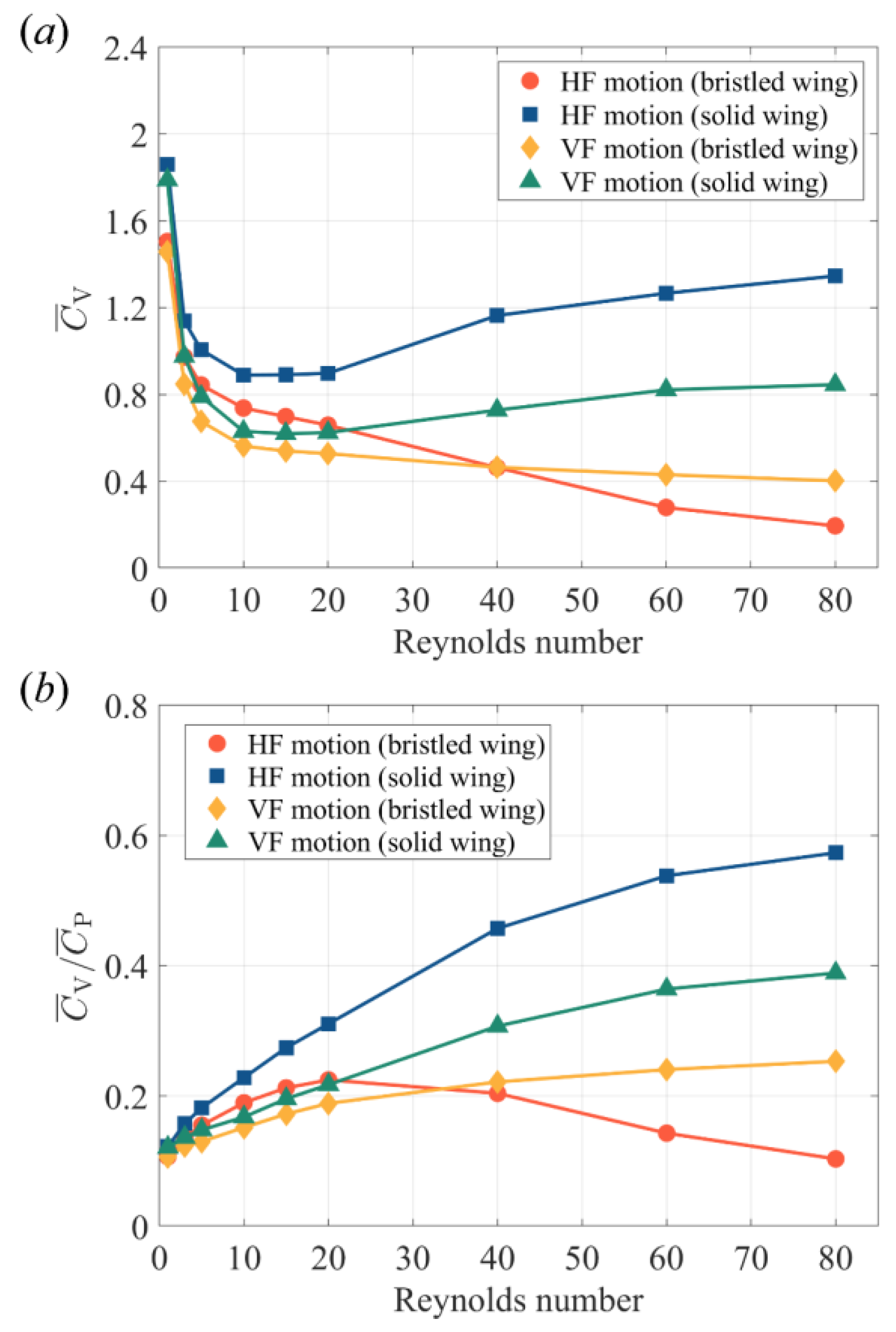
- A bristled wing has higher and when using a lift-based mechanism than when using a drag-based mechanism at 5 < Re < 40. This Re range covers the most probable flight Re of minute bristled-wing insects. If Re < 5, for both mechanisms, rapidly increases and drops, and tends to converge at one point. When 1 < Re < 80, regardless of the mechanism used, the and of a bristled wing are lower than those of a solid wing with the same mechanism. Nevertheless, as Re declines, the aerodynamic differences between the bristled wing and solid wing decrease. At Re < 10, a bristled wing can produce more than 80% of the produced by a solid wing in the same flapping mode, while the cross-sectional area of the bristled wing model is only 23.7% of that of the solid wing model.
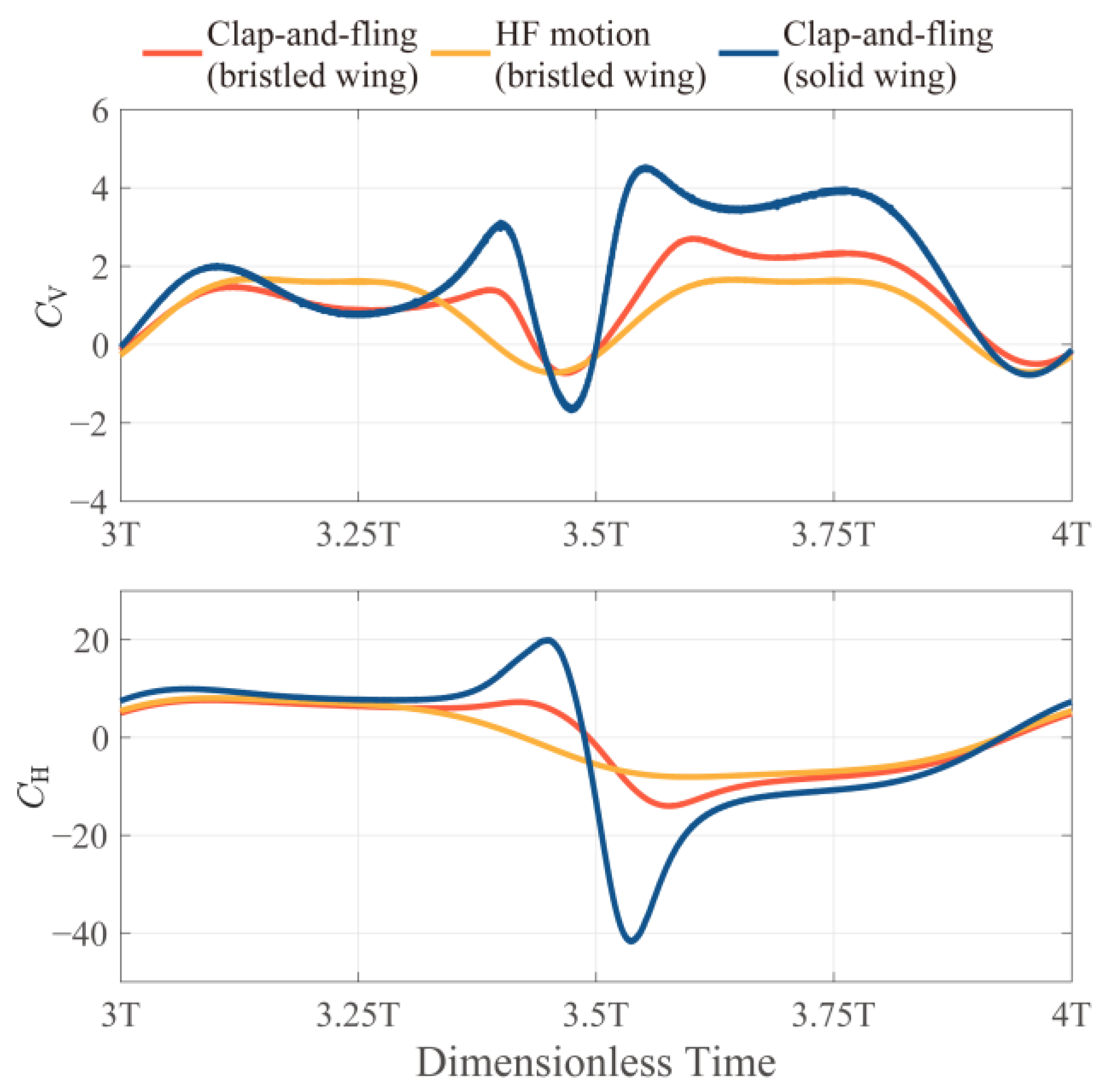
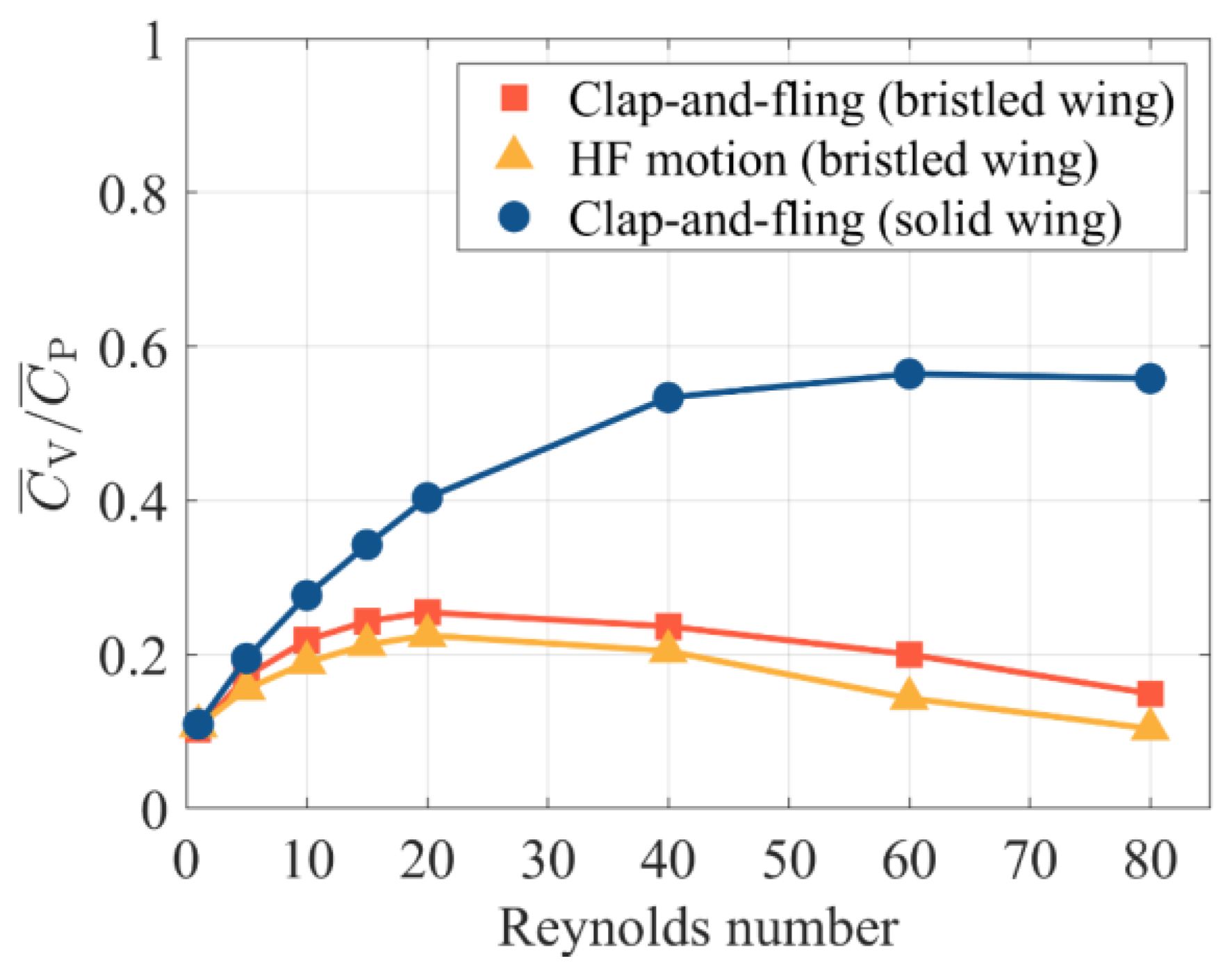
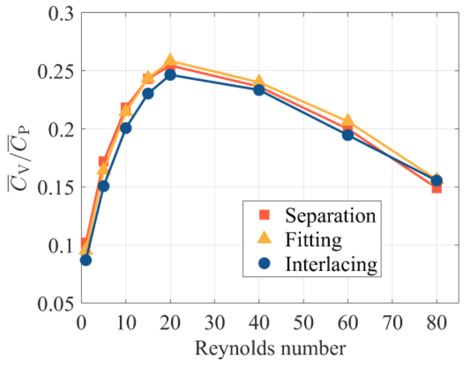
- When Re < 40, bristled wings in clap-and-fling motion can achieve augmentation of more than 30%. Particularly, when Re = 5, which approaches the flight Re of minute bristled-wing insects, the augmentation can be up to 50%. In contrast, when 5 < Re < 20, the augmentation of solid wings in clap-and-fling is close to 70%, but at the expense of a higher . Due to the unique morphology of bristled wings, they may cross each other when they “clap” together. We envisaged three clap-and-fling patterns with different inter-wing gaps, namely, “separation”, “fitting”, and “interlacing” clap-and-fling. The simulation results indicate that the values of these three patterns are very close. At Re < 60, “interlacing” clap-and-fling produces substantial , resulting in a lower aerodynamic efficiency than the other two patterns.
Author Contributions
Funding
Institutional Review Board Statement
Informed Consent Statement
Data Availability Statement
Acknowledgments
Conflicts of Interest
Appendix A
References
- Dudley, R. The Biomechanics of Insect Flight: Form, Function, Evolution; Princeton University Press: Princeton, NJ, USA, 2002; ISBN 0-691-09491-8. [Google Scholar]
- Polilov, A.A. Small Is Beautiful: Features of the Smallest Insects and Limits to Miniaturization. Annu. Rev. Entomol. 2015, 60, 103–121. [Google Scholar] [CrossRef] [PubMed]
- Huber, J.T.; Beardsley, J.W. A New Genus of Fairyfly, Kikiki, from the Hawaiian Islands (Hymenoptera: Mymaridae). Proc. Hawaiian Entomol. Soc. 2000, 34, 65–70. [Google Scholar]
- Viggiani, G.; Bernardo, U. Two Species of Megaphragma (Hymenoptera Trichogrammatidae), Egg-Parasitoids of Heliothrips Haemorrhoidalis Bouché (Thysanoptera) in Southern Italy, with Description of a New Species. Boll. Zool. Agrar. Bachic. Ser. II 1997, 29, 51–55. [Google Scholar]
- Mills, N. Egg Parasitoids in Biological Control and Integrated Pest Management. In Egg Parasitoids in Agroecosystems with Emphasis on Trichogramma; Springer: Berlin/Heidelberg, Germany, 2009; pp. 389–411. [Google Scholar]
- Bonnet, J.; Yin, P.; Ortiz, M.E.; Subsoontorn, P.; Endy, D. Controlled Flight of a Biologically Inspired, Insect-Scale Robot. Science 2013, 340, 599–603. [Google Scholar] [CrossRef]
- Ward, S.; Foroutan, V.; Majumdar, R.; Mahdavipour, O.; Hussain, S.A.; Paprotny, I. Towards Microscale Flight: Fabrication, Stability Analysis, and Initial Flight Experiments for 300 Μm × 300 Μm × 1.5 Μm Sized Untethered MEMS Microfliers. IEEE Trans. NanoBioscience 2015, 14, 323–331. [Google Scholar] [CrossRef]
- Kim, B.H.; Li, K.; Kim, J.-T.; Park, Y.; Jang, H.; Wang, X.; Xie, Z.; Won, S.M.; Yoon, H.-J.; Lee, G.; et al. Three-Dimensional Electronic Microfliers Inspired by Wind-Dispersed Seeds. Nature 2021, 597, 503–510. [Google Scholar] [CrossRef]
- Qiu, T.; Lee, T.-C.; Mark, A.G.; Morozov, K.I.; Münster, R.; Mierka, O.; Turek, S.; Leshansky, A.M.; Fischer, P. Swimming by Reciprocal Motion at Low Reynolds Number. Nat. Commun. 2014, 5, 5119. [Google Scholar] [CrossRef] [Green Version]
- Farisenkov, S.E.; Kolomenskiy, D.; Petrov, P.N.; Engels, T.; Lapina, N.A.; Lehmann, F.-O.; Onishi, R.; Liu, H.; Polilov, A.A. Novel Flight Style and Light Wings Boost Flight Performance of Tiny Beetles. Nature 2022, 602, 96–100. [Google Scholar] [CrossRef]
- Sunada, S.; Takashima, H.; Hattori, T.; Yasuda, K.; Kawachi, K. Fluid-Dynamic Characteristics of a Bristled Wing. J. Exp. Biol. 2002, 205, 2737. [Google Scholar] [CrossRef]
- Takahashi, H.; Sato, K.; Nguyen, M.-D.; Matsumoto, K.; Shimoyama, I. Characteristic Evaluation of a Bristled Wing Using Mechanical Models of a Thrips Wings with MEMS Piezoresistive Cantilevers. J. Biomech. Sci. Eng. 2015, 10, 14-00233. [Google Scholar] [CrossRef] [Green Version]
- Barta, E.; Weihs, D. Creeping Flow around a Finite Row of Slender Bodies in Close Proximity. J. Fluid Mech. 2006, 551, 1–17. [Google Scholar] [CrossRef]
- Weihs, D.; Barta, E. Comb Wings for Flapping Flight at Extremely Low Reynolds Numbers. AIAA J. 2008, 46, 285–288. [Google Scholar] [CrossRef]
- Davidi, G.; Weihs, D. Flow Around a Comb Wing in Low-Reynolds-Number Flow. AIAA J. 2012, 50, 249–253. [Google Scholar] [CrossRef]
- Santhanakrishnan, A.; Robinson, A.K.; Jones, S.; Low, A.A.; Gadi, S.; Hedrick, T.L.; Miller, L.A. Clap and Fling Mechanism with Interacting Porous Wings in Tiny Insect Flight. J. Exp. Biol. 2014, 217, 3898–3909. [Google Scholar] [CrossRef] [PubMed] [Green Version]
- Jones, S.K.; Yun, Y.J.J.; Hedrick, T.L.; Griffith, B.E.; Miller, L.A. Bristles Reduce the Force Required to ‘Fling’ Wings Apart in the Smallest Insects. J. Exp. Biol. 2016, 219, 3759–3772. [Google Scholar] [CrossRef] [Green Version]
- Wu, Y.K.; Sun, M.; Liu, Y.P. The Wing−wing Interaction Mechanism of Bristled Wing Pair in Fling Motion. Phys. Fluids 2022, 34, 071903. [Google Scholar] [CrossRef]
- Ford, M.P.; Kasoju, V.T.; Gaddam, M.G.; Santhanakrishnan, A. Aerodynamic Effects of Varying Solid Surface Area of Bristled Wings Performing Clap and Fling. Bioinspiration Biomim. 2019, 14, 046003. [Google Scholar] [CrossRef]
- Kasoju, V.; Terrill, C.; Ford, M.; Santhanakrishnan, A. Leaky Flow through Simplified Physical Models of Bristled Wings of Tiny Insects during Clap and Fling. Fluids 2018, 3, 44. [Google Scholar] [CrossRef] [Green Version]
- Kasoju, V.T.; Santhanakrishnan, A. Aerodynamic Interaction of Bristled Wing Pairs in Fling. Phys. Fluids 2021, 33, 031901. [Google Scholar] [CrossRef]
- Lee, S.H.; Lahooti, M.; Kim, D. Aerodynamic Characteristics of Unsteady Gap Flow in a Bristled Wing. Phys. Fluids 2018, 30, 071901. [Google Scholar] [CrossRef]
- Ristroph, L.; Bergou, A.J.; Guckenheimer, J.; Wang, Z.J.; Cohen, I. Paddling Mode of Forward Flight in Insects. Phys. Rev. Lett. 2011, 106, 178103. [Google Scholar] [CrossRef] [PubMed] [Green Version]
- Vogel, S. Modes and Scaling in Aquatic Locomotion. Integr. Comp. Biol. 2008, 48, 702–712. [Google Scholar] [CrossRef] [PubMed]
- Jones, S.K.; Laurenza, R.; Hedrick, T.L.; Griffith, B.E.; Miller, L.A. Lift vs. Drag Based Mechanisms for Vertical Force Production in the Smallest Flying Insects. J. Theor. Biol. 2015, 384, 105–120. [Google Scholar] [CrossRef] [PubMed] [Green Version]
- Engels, T.; Kolomenskiy, D.; Lehmann, F.-O. Flight Efficiency Is a Key to Diverse Wing Morphologies in Small Insects. J. R. Soc. Interface 2021, 18, 20210518. [Google Scholar] [CrossRef] [PubMed]
- Weis-Fogh, T. Quick Estimates of Flight Fitness in Hovering Animals, Including Novel Mechanisms for Lift Production. J. Exp. Biol. 1973, 59, 169. [Google Scholar] [CrossRef]
- Sane, S.P. Neurobiology and Biomechanics of Flight in Miniature Insects. Curr. Opin. Neurobiol. 2016, 41, 158–166. [Google Scholar] [CrossRef]
- Ellington, C. Wing Mechanics and Take-off Preparation of Thrips (Thysanoptera). J. Exp. Biol. 1980, 85, 129–136. [Google Scholar] [CrossRef]
- Ellington, C. The Aerodynamics of Hovering Insect Flight. III. Kinematics. Philos. Trans. R. Soc. Lond. B Biol. Sci. 1984, 305, 41–78. [Google Scholar]
- Miller, L.A.; Peskin, C.S. Flexible Clap and Fling in Tiny Insect Flight. J. Exp. Biol. 2009, 212, 3076–3090. [Google Scholar] [CrossRef] [Green Version]
- Götz, K.G. Course-Control, Metabolism and Wing Interference during Ultralong Tethered Flight in Drosophila Melanogaster. J. Exp. Biol. 1987, 128, 35–46. [Google Scholar] [CrossRef]
- Srygley, R.B.; Thomas, A.L.R. Unconventional Lift-Generating Mechanisms in Free-Flying Butterflies. Nature 2002, 420, 660–664. [Google Scholar] [CrossRef] [PubMed]
- Jin, X.-X.; Li, C.-D. A New Species of Ptilomymar (Hymenoptera, Mymaridae) and a Key to the Described Species. Zookeys 2014, 439, 127–134. [Google Scholar] [CrossRef] [Green Version]
- Jin, X.-X.; Li, C.-D. First Record of Eubroncus (Hymenoptera, Mymaridae) from China, with Description of Three New Species. Zookeys 2014, 399, 29–41. [Google Scholar] [CrossRef]
- Jin, X.-X.; Li, C. A New Species of Australomymar (Hymenoptera: Mymaridae), with a Key to Species. Turk. J. Zool 2015, 39, 421–424. [Google Scholar] [CrossRef]
- Jin, X.-X.; Li, C.-D.; Yang, J.-C. Description of Three New Species of Arescon Walker (Hymenoptera, Mymaridae) from China. Zookeys 2016, 584, 83–94. [Google Scholar] [CrossRef] [PubMed] [Green Version]
- Jin, X.-X.; Li, C. First Report of Platystethynium with Description of a New Species and Two Other New Records from China (Hymenoptera: Mymaridae). J. For. Res. 2016, 27, 203–207. [Google Scholar] [CrossRef]
- Jin, X.-X. A Taxonomic Study of Chinese Species of Mymaridae (Hymenoptera: Chalcidoidea). Ph.D. Thesis, Northeast Forestry University, Harbin, China, 2015. [Google Scholar]
- Pricop, E. Preliminary Studies of the Mymaridae (Hym., Chalcidoidea) from Neamţ County, Romania, Species Distribution, Vascular Flora/Vegetation, an Ecological Approach. Anim. Biol. Anim. Husb. 2009, 1, 13–29. [Google Scholar]
- Liu, W.; Sun, M. Aerodynamics and Three-Dimensional Effect of a Translating Bristled Wing at Low Reynolds Numbers. Sci. Rep. 2022, 12, 14966. [Google Scholar] [CrossRef]
- Layton, S.K.; Krishnan, A.; Barba, L.A. CuIBM–A GPU-Accelerated Immersed Boundary Method. arXiv 2011, preprint. arXiv:1109.3524. [Google Scholar]
- Taira, K.; Colonius, T. The Immersed Boundary Method: A Projection Approach. J. Comput. Phys. 2007, 225, 2118–2137. [Google Scholar] [CrossRef]
- Krishnan, A. Towards the Study of Flying Snake Aerodynamics, and an Analysis of the Direct Forcing Method. Ph.D. Thesis, Boston University, Boston, MA, USA, 2015. [Google Scholar]
- Wang, Z.J. Unsteady Forces and Flows in Low Reynolds Number Hovering Flight: Two-Dimensional Computations vs Robotic Wing Experiments. J. Exp. Biol. 2004, 207, 449–460. [Google Scholar] [CrossRef] [PubMed] [Green Version]
- Arora, N.; Gupta, A.; Sanghi, S.; Aono, H.; Shyy, W. Lift-Drag and Flow Structures Associated with the “Clap and Fling” Motion. Phys. Fluids 2014, 26, 071906. [Google Scholar] [CrossRef]


| Cases | Size of Uniform Region |
|---|---|
| HF motion | 3.5c × 2c |
| VF motion | 2c × 4c |
| Clap-and-fling | 6c × 2c |
| 0.002c | 0.004c | 0.008c | |
|---|---|---|---|
| Grid Number | 2594 × 1854 | 1583 × 1220 | 1012 × 834 |
| (Re = 10) | 0.8821 | 0.9072 | 0.9481 |
| (Re = 10) | -- | 2.85% | 4.51% |
| Re | 1 | 10 | 20 | 40 | 60 | |
|---|---|---|---|---|---|---|
| of three patterns | “Interlacing” | 0.0871 | 0.2007 | 0.2465 | 0.2335 | 0.1946 |
| “Separation” | 0.1021 | 0.2185 | 0.2545 | 0.2364 | 0.2000 | |
| “Fitting” | 0.0954 | 0.2147 | 0.2584 | 0.2401 | 0.2064 | |
| Ratio of “interlacing” pattern’s to that of other two patterns | Ratio to “separation” | 85.3% | 91.9% | 96.8% | 98.8% | 97.3% |
| Ratio to “fitting” | 91.3% | 93.4% | 95.3% | 97.2% | 94.2% | |
Publisher’s Note: MDPI stays neutral with regard to jurisdictional claims in published maps and institutional affiliations. |
© 2022 by the authors. Licensee MDPI, Basel, Switzerland. This article is an open access article distributed under the terms and conditions of the Creative Commons Attribution (CC BY) license (https://creativecommons.org/licenses/by/4.0/).
Share and Cite
Shen, T.; Tu, Z.; Li, D.; Kan, Z.; Xiang, J. Aerodynamic Characteristics of Bristled Wings in Flapping Flight. Aerospace 2022, 9, 605. https://doi.org/10.3390/aerospace9100605
Shen T, Tu Z, Li D, Kan Z, Xiang J. Aerodynamic Characteristics of Bristled Wings in Flapping Flight. Aerospace. 2022; 9(10):605. https://doi.org/10.3390/aerospace9100605
Chicago/Turabian StyleShen, Tong, Zhan Tu, Daochun Li, Zi Kan, and Jinwu Xiang. 2022. "Aerodynamic Characteristics of Bristled Wings in Flapping Flight" Aerospace 9, no. 10: 605. https://doi.org/10.3390/aerospace9100605
APA StyleShen, T., Tu, Z., Li, D., Kan, Z., & Xiang, J. (2022). Aerodynamic Characteristics of Bristled Wings in Flapping Flight. Aerospace, 9(10), 605. https://doi.org/10.3390/aerospace9100605