Abstract
This paper introduces the realization and wind tunnel testing of a novel variable camber wing equipped with compliant morphing trailing edges. Based on the aerodynamic shape and compliant mechanisms that were optimized in advance, a wind tunnel model called mTE4 was developed, in which the rigid leading edge, rigid wing box, and compliant trailing edge were manufactured by 3D printing technology using three different materials. Due to difficulties in the detailed design of a small-scale model, special attention is devoted to the implementation procedure. Additionally, the static and dynamic characteristics of the proposed wind tunnel model were evaluated by ground tests, and the aerodynamic characteristics were evaluated by numerical methods. Then, the aerodynamic performance and the static aeroelastic deformation of the compliant trailing edge were investigated in a low-speed wind tunnel. The load-bearing ability of the proposed compliant morphing trailing edge device was validated and the continuous outer mold surface was found to persist throughout the entire testing period. Notably, a maximum deflection range of 37.9° at the airspeed of 15 m/s was achieved. Additionally, stall mitigation was also achieved by periodically deflecting the morphing trailing edge, enabling a stall angle delay of approximately 1° and 13% increase in post-stall lift coefficient. Finally, the development procedure was validated by comparing the lift between numerical and experimental results.
1. Introduction
Intensifying environmental awareness around the world is pushing aeronautical engineers to increase aircraft efficiency. Morphing aircrafts are believed to contribute to fuel saving by maintaining an excellent aerodynamic performance over the entire flight envelope, which means that this technology may help to achieve carbon neutrality in the future [1]. By actively changing their local or global shapes to adapt to different flight missions, speeds, or conditions, morphing aircrafts can satisfy multi-mission requirements with different aerodynamic shapes and configurations. Among the various research topics, camber morphing is one of the most promising candidates [2,3,4].
Compared with a conventional wing equipped with discontinuous control surfaces, the camber morphing wing conformably modifies the wing shape and eliminates the drag penalties attributed to the gaps between panels. From a design perspective, a variable camber wing can easily be fulfilled with few actuation requirements in terms of mechanical design and has little influence on the inertia and elastic forces despite having a large influence on the aerodynamic force, producing considerable comprehensive benefits.
Since the proposition of the variable camber wing concept, researchers have been committed to developing a comprehensive design solution to integrate structure, mechanisms, actuators, and elastic skin using existing technologies. The main research projects of the last 10 years are listed in Table 1. Common solutions to the trailing edge for variable camber wings can be divided into three categories: traditional mechanism solutions (including hinged ribs [5] and the eccentric beam [6]), compliant structure solutions (including belt-rib [7], Fishbone Active Camber concept [8] and compliant mechanisms [9]) and skin-driven solutions.

Table 1.
Major variable camber wing research projects.
Compliant mechanisms are modern mechanisms that work as a replacement for traditional rigid-body mechanisms, which generally fulfill specific functions, relying on their distributed structural flexibility. As a monolithic structure, compliant mechanisms can minimize the use of hinges, and are free from friction and lubrication. Furthermore, because of the reduction in assembly complexity, compliant mechanisms can help to improve accuracy and reliability [33]. Nonlinear instability problems induced by seams can also be avoided, which is conducive to weight reduction and equipment manufacturing. Without relying on complex distributed and embedded actuators, compliant mechanisms place more emphasis on the utilization of a limited number of traditional actuators connected to a compliant structure with reasonable stiffness distribution, transferring force and movement through elastic deformation. Distributed deformation helps to reduce structural stress, prolong anti-fatigue life, and increase service reliability. Initially introduced by FlexSys in 1998, compliant mechanisms are expected to be a feasible solution for a smooth, light, and load-bearing variable camber trailing edge wing [34].
Research on morphing trailing edges based on the concept of the compliant mechanism is shown in Figure 1. In 1998, the AFRL supported FlexSys in the adoption of the concept of a compliant mechanism to design wings with leading and trailing edges [34]. The earliest literature reports the adoption of a single torsional actuator to control the leading and trailing edge compliant structure of airfoil to achieve an active shape change. To test its real load-bearing capacity and aerodynamic benefits, a straight wing model with a 1.27 m span and 0.762 m chord was designed in 2006, with the morphing trailing edge mounted within the last 30% chord length. The model successively underwent a wind tunnel test and aircraft mount test, showing that it fulfilled ±10° deflection with a deflection rate of 30°/second at the speed of Mach 0.55 [35]. Later, additional improvements were made and achieved a 9° upward deflection and 40° downward deflection. They replaced the inboard flaps on Gulfstream III with an active compliant variable camber trailing edge, which proved to be a success in the 2016 flight test. At a maximum speed of Mach 0.75, the compliant trailing edge operated normally under 18.4 kPa dynamic pressure [36]. Gaspari and Ricci employed an aerodynamic shape optimization approach to obtain an airfoil profile and derived the internal structure through the load path representation method for compliant mechanisms [37]. Subsequently, they designed and created a wind tunnel model with a span of 930 mm and a chord length of 418 mm in 2016. With its main structure fabricated of aluminum alloy and flexible leading and trailing edges fabricated of nylon, the model was fabricated with 3D printing technology, achieving a 10° deflection amplitude of the trailing edge. They carried out a test in the wind tunnel of Politecnico di Milano, where the maximum wind speed was 40 m/s. Pressure coefficients are measured by pressure sensors mounted on the wing surface. By comparison, with the simulated data, the feasibility of the design procedure adopted for the synthesis of the structures was validated [38]. Northwestern Polytechnical University also carried out relevant research in this field. Recently, they designed a variable camber mechanism with compliant leading and trailing edges with large deformation capacity. Actuated by two rotary servo motors, the rotary motion is converted into linear motion via a leadscrew, driving the internal compliant mechanism to deform [39].
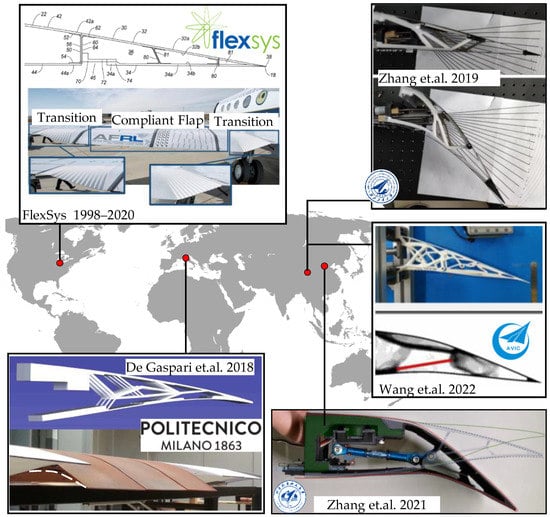
Figure 1.
Trailing edge morphing solution by compliant mechanisms [1,34,35,36,37,38,39].
Nevertheless, the design of this type of device is sophisticated, and requires specialized design methodologies, including shape parameterization for variable cambers, aerodynamic shape optimization for target shapes, and the synthesis of compliant mechanisms. Furthermore, the conflicting load-bearing and morphing requirements need compromise. Prevalent concepts are under development with insufficient implementation and experimental validation.
Our research aimed to establish a systematic design framework for a variable camber wing with potential applications in a medium-scale unmanned aerial vehicle (UAV). The whole project comprised the design, analysis, manufacture, and validation of the variable camber wing based on compliant mechanisms. The trailing edge shape was first optimized, subject to both the aerodynamic performance and kinematic relation of mechanisms. Then, the planner-compliant mechanisms were designed and extended to the morphing trailing edge wing, capable of smoothly deforming along the chordwise direction. Finally, ground and wind tunnel tests were carried out for evaluation. The whole project provides methodologies for the design of a variable camber wing and contributes a reference for the future development of morphing aircraft.
This paper documents a part of this project, focusing on the “manufacturing–evaluation” aspect. The aim of this work is to promote the development of morphing wings from the concept stage to a more detailed model, and then evaluate the model through numerical analysis and wind tunnel experiments.
The paper is organized as follows: In Section 2, the variable camber morphing wing is developed and analyzed to provide structural properties and numerical aerodynamic characteristics. Section 3 describes the wind tunnel setup, including the overall layout, model installation, servo system, measurements, etc. Section 4 reports the aerodynamic characteristics with different actuation inputs, angles of attack, and airspeeds. Section 5 investigates the static aeroelastic behavior of the wing. Section 6 explores the applications in stall mitigation using an active vibrating trailing edge. Section 7 presents the conclusions.
2. Variable Camber Morphing Wing
This section presents the development, structural analysis, and numerical aerodynamic simulation of the wind tunnel model mTE4. The variable camber morphing wing model was designed with an optimized airfoil shape and compliant mechanisms. Then, the modal and dynamic characteristics were evaluated by ground tests. At last, the numerical aerodynamic characteristics were investigated.
2.1. Design Methodology
A low-speed airfoil was optimized to obtain the target airfoil with the objective of maximizing the lift and constraints determined by the limitations of the subsequent compliant structure [40]. The baseline airfoil was derived from an electric UAV developed by Beihang university. Some of the basic tools needed for this process are:
- A proper airfoil shape parametrization method, class–shape transformation (CST) , is used to describe the airfoil profile. As a combination of class and shape functions, class–shape transformation (CST) is a popular method of creating analytical representations of the surface coordinates of aerospace vehicles [41];
- A hybrid mesh deformation strategy consists of the deformation of the surface mesh by a radial basis function (RBF) tool, and the deformation of the surrounding volume mesh by the formulation of linear elasticity. The radial basis function is a real-valued function whose value depends only on the distance to the origin. It was first used to deal with the surface fitting problem of aircraft shape design by Hardy in 1971 [42];
- SU2 is an open-source suite for multiphysics simulation and design. It is a collection of software tools written in C++ and Python for the analysis of partial differential equations (PDEs) and PDE-constrained optimization problems on unstructured meshes with state-of-the-art numerical methods [43]. This was used as an aerodynamic and adjoint solver. Our analyses were carried out using fully turbulent fields that do not account for boundary layer transition.
In other words, theoretically, the optimal shape can be achieved by deflecting the trailing edge of the baseline airfoil, and its advantage lies in its maximized lift. The optimization aims for the trailing edge to deflect 15° downward under taking-off conditions, with an angle of attack of 5°, airspeed of 15 m/s and Reynolds number of 300,000. The baseline profile and the optimized airfoil are shown in Figure 2, and their aerodynamic coefficient comparison is shown in Figure 3.
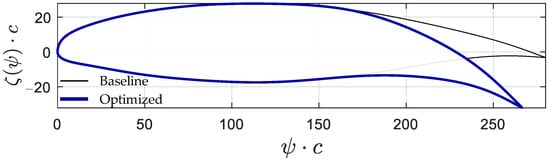
Figure 2.
Profile of the baseline and optimized airfoil.
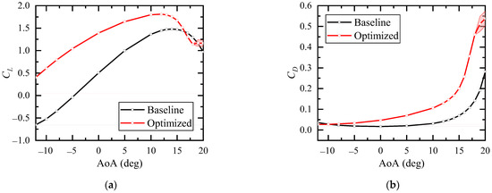
Figure 3.
Comparison of the aerodynamic coefficient for the baseline and the optimized airfoil. (a) Lift coefficient. (b) Drag coefficient.
Then, the optimal airfoil obtained above was used as input to design the compliant mechanisms. The structural topology optimization method was adopted to achieve the target deformation under the action of a suitable driving force, using the load path method that includes the design space definition, the base structure generation, the establishment of the load path library and the treatment of skin dimensions [44,45]. After that, the topology and sizing optimization of the compliant mechanisms with deformation accuracy as the target were solved, and the results are shown in Figure 4 [46].
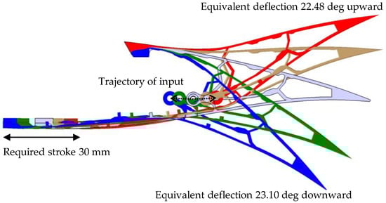
Figure 4.
Trailing edge deformation for optimized structure (actuation input is limited within ±60°).
After obtaining the aerodynamic and structural profile, we can proceed to the wing development.
2.2. Wind Tunnel Model
A demonstrator with a variable camber named Morphing Trailing Edge Wing Version 4 (mTE4) was developed and manufactured, and the layout is illustrated in Figure 5. The model consisted of a leading edge, a wing box, and a compliant morphing trailing edge. The rigid leading edge was used to provide the aerodynamic profile. The wing box with high stiffness is the main supporting structure of the prototype, connecting the leading edge and the trailing edge. The compliant trailing edge is the main deformation component, playing the role of an aerodynamic control surface. All three of the above parts were manufactured by 3D printing. Considering the pricing, elasticity, surface roughness, and other limits, different materials were used for those parts, as indicated in Table 2.
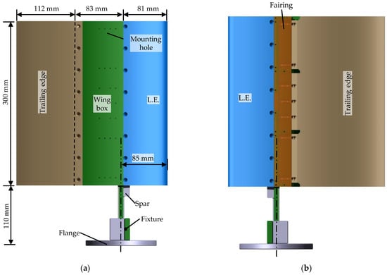
Figure 5.
Front and back view of mTE4. (a) Upper surface. (b) Lower surface.
Table 2.
Material used for mTE4 [47].
Figure 6 shows an isometric drawing of mTE4, and Figure 7 demonstrates the wing box, providing more model details. Owing to the limitations of the 3D printer, the chord length of the prototype was 276 mm, and the span length was 300 mm. Both the leading edge and the compliant morphing trailing edge were bolted to the wing box. The MR3 slide rail was fixed to the lower surface of the wing box, while small holes were punched on the upper surface to facilitate assembly of the slides. The length of slider rail was 50 mm, which provides sufficient length for sliding. The MR3M sliders were mounted on the lower surface of the compliant morphing trailing edge using two M1.6 × 5 countersunk screws. Additionally, the slide rail was covered by a carbon filer composite with a size of 300 × 45 × 0.5 mm as fairing, which maintains the smoothness of the lower surface, as shown in Figure 7. In addition, the main spar fabricated of stainless steel was bolted to the wing box and extended beyond the wing root, allowing for the entire prototype to be installed on the force balance by a fixture and a flange. The stainless steel main spar enhanced the spanwise stiffness of the wing model.
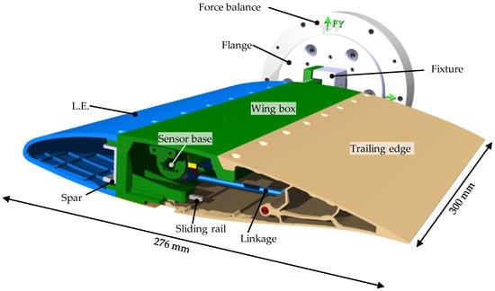
Figure 6.
Isometric drawing of mTE4.
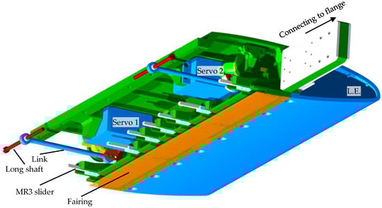
Figure 7.
Wing box and leading edge of mTE4.
The variable camber trailing edge system is the core component of the prototype, as shown in Figure 8, which consists of the compliant mechanisms of the trailing edge, two servo-link drive systems, and two sensor systems.
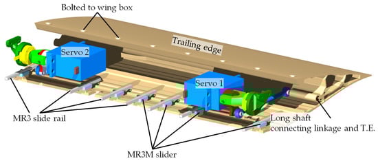
Figure 8.
The compliant mechanisms–actuation–sensor subsystem of mTE4.
The two servo-link drive systems were symmetrically mounted in the wing box and connected to the trailing edge, as shown in Figure 9. The servo was hinged to a 68 mm long shaft mounted in the compliant trailing edge through a servo arm and a long linkage. The two servos that provided power are Futaba HPS-A700 high-performance brushless servos with a size of 40.5 × 21.0 × 39.4 mm and weight of 82 g. This can achieve a maximum rotation speed of 500° per seconds and a maximum torque of 7.25 N·m at a rated voltage of 7.4 V. Due to the symmetrical installation, the anti-phase synchronization operation was adopted.
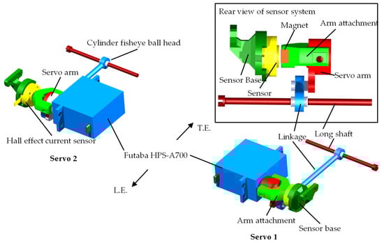
Figure 9.
Actuation and sensor subsystems of mTE4.
The sensor system was also installed, as shown in Figure 9. Two (one per actuator) non-contact Hall angle sensors were used to concurrently measure the servos’ rotation angle of servos and were mounted co-axially with the servo arms. The rear view of the sensor system demonstrates that an arm attachment was employed on the servo arm with a Rubidium magnet buried at the end; a Hall angle sensor was mounted on the wing box; a 1 mm gap was left between the sensor and the Rubidium magnet. These sensors measured the strength of the magnetic field induced by the current flow through the servo arm and generated an output voltage that is directly proportional to the current magnitude.
2.3. Structural Properties
2.3.1. Modal Analysis
Ground vibration tests were conducted when the servo actuator was activated, and accelerometers were used to measure the out-of-plane response. The exciting frequency up to 512 Hz, and the natural modes of vibration below 100 Hz were analyzed. With the actuation input of 40°, the trailing edge deflected downwards; the modes of mTE4 are shown in Figure 10. The first-order mode is the trailing edge deflection with a frequency of 37.06 Hz, while the second-order mode is torsion with a frequency of 64.53 Hz.
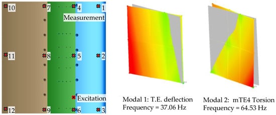
Figure 10.
The first two modes of mTE4.
The relationship between the frequencies and the actuation inputs of mTE4 is shown in Figure 11. The deflection of the trailing edge changes the dynamics of the wing. Overall, the deflection of the trailing edge increases the structural natural frequency. This is because the deformation increases the internal stresses and the strain energy, which has a stiffening effect on the structure.
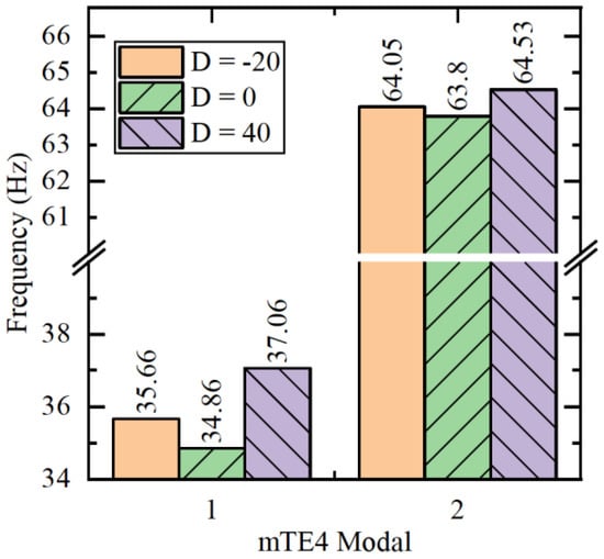
Figure 11.
Experimental modal analysis of mTE4 at different actuation inputs.
2.3.2. Dynamic Characteristics
The dynamic characteristics of the variable camber trailing edge system were investigated by frequency sweep. Stepped sine signals with amplitudes of 2 and 4° were used as the actuation inputs u. The frequency ranged from 0.3 Hz to 10 Hz, with an interval of 0.2 Hz.
The time domain results for a frequency sweep of mTE4 with an actuation input (represented by D) of −20° and amplitude (represented by A) of 4° are shown in Figure 12. ym represents the distance that the trailing edge slides on the slide rail (detected by laser displacement sensor), ys1 and ys2 represents the rotation angle measured by the two angle sensors with unit of degree.
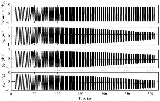
Figure 12.
Frequency sweep result for mTE4 (actuation input D −20°, amplitude 4°).
The time domain signals of the actuation input u to trailing edge sliding distance ym and u to servo 2 rotation ys2 in Figure 12 were analyzed in the frequency domain, and the magnitude–frequency characteristics were obtained, as shown in Figure 13. The gain and phase all decreased with increasing frequency in the swept range.
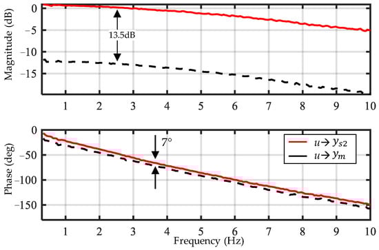
Figure 13.
Bode diagram for mTE4 (actuation angle D −20°, amplitude 4°).
2.4. Numerical Aerodynamic Simulation
The lift characteristics of proposed morphing wing was numerically investigated at the freestream velocity of 25 m/s. The comparison of lift coefficients between the deformed wing with 15° downward deflection and the undeformed wing was fabricated.
2.4.1. Numerical Methodologies
The aerodynamic results were obtained by solving the incompressible Reynolds-averaged Navier–Stokes (RANS) equations combined with the Shear Stress Transport (SST) turbulence model. The operating Reynolds number is 500,000 and the freestream turbulence intensity is 0.25%. Concerning the numerical settings of the flow solver, the Flux Difference Splitting (FDS) second order upwind schemes with low-speed preconditioning was adopted for the discretization of convective fluxes.
The unstructured mesh and the corresponding boundary conditions are shown in Figure 14, where c is the chord length and b is the span of the wing. The mesh for 3D simulation contains 2.26 million nodes and 2.21 million cells. In detail, the computational grid comprises a circular rotating zone (inner sub-domain) and a rectangular stationary zone (outer sub-domain), which are coupled through the interface. By rotating the inner subdomain, various angles of attack can be easily achieved without mesh regeneration. In particular, the grids near the wing are refined. The initial wall normal grid points for boundary layer mesh are located at 1.5 × 10⁻⁵ m with a growth rate of 1.05, and the corresponding y+ ≈ 1.15. This mesh was tested for grid independence to ensure that further mesh refinement does not change the lift coefficient significantly.
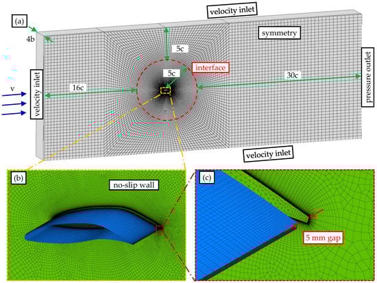
Figure 14.
Computational mesh for the deformed wing. (a) Full view. (b) Zoom-in mesh detail around the airfoil. (c) Zoom-in mesh detail near the trailing edge.
Figure 15 shows the top view of the mesh. The details of the wing model, the 5 mm gap, and the wall are shown in Figure 15b. The gap and no-slip wall condition were set to simulate the presence of the end plates.
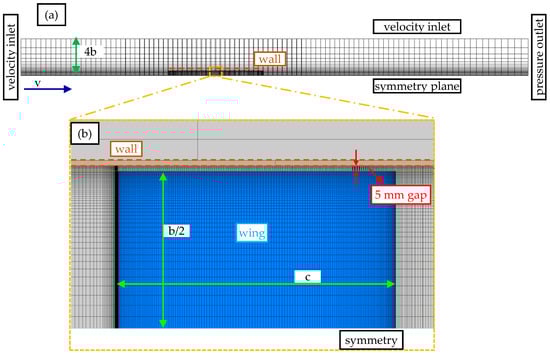
Figure 15.
Top view of the computational mesh for the deformed wing. (a) Full view. (b) Cutting plane for Zoom-in mesh detail around the airfoil.
2.4.2. Results
The comparison of lift coefficients between the deformed and undeformed wing at −5, 0, 5, 10, 13, and 16° is shown in Figure 16. As the morphing trailing edge deflects 15° downward, the lift coefficient increases while the slope of the lift curve remains roughly the same.
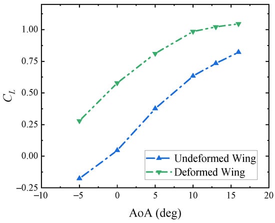
Figure 16.
Comparison of lift coefficients between deformed and undeformed wing.
Figure 17 plots the pressure coefficient distributions and streamlines for the deformed and undeformed wing at an angle of attack of 5°. In the wind tunnel, the model experiences a different induced angle due to the presence of the walls and three-dimensional effects due to the finite aspect ratio. Compared with the undeformed wing, the camber of deformed wing increases, causing stronger separation of the flow near the trailing edge.
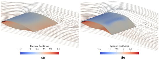
Figure 17.
Pressure coefficient distributions and streamlines of the undeformed and deformed wing (with 15° downward deflection) at a 5° angle of attack. (a) Undeformed wing. (b) Deformed wing.
3. Wind Tunnel Setup
A wind tunnel experiment was performed to assess the aerodynamic and aeroelastic performance of mTE4. This experiment was conducted in a low-speed wind tunnel with a rectangular opening section equipped with a sideslip platform, force balance, and digital image correlation (DIC) [48] system, with the ability to measure the forces, moments, and displacement of the prototype. The characteristics investigated in the wind tunnel test are as follows:
- Aerodynamic characteristics of mTE4 with different actuation inputs, airspeeds and angles of attack;
- Aeroelastic characteristics with different actuation inputs;
- Stall mitigation by trailing edge vibration with different frequencies and amplitudes.
The tests were performed at speeds of 10, 15, and 25 m/s. Considering the chord of the wing c = 0.276 m, the resulting Reynolds numbers were 200,000, 300,000, and 500,000. The angles of attack varied from −15 to 30°, and the actuation input angle varied from −55 to 55°. For the convenience of presentation, only a portion of the data were used in the subsequent analysis, following the descriptions in each subsection.
An overview of the wind tunnel is shown in Figure 18. The model was mounted vertically and attached to the sideslip platform by a force balance. Therefore, the model‘s angle of attack was changed using the sideslip angle platform with an accuracy of 0.01°. Additionally, two end plates were mounted on the framework, positioned on the top and bottom of the model to mitigate the three-dimensional effect. There was a 5 mm gap between the end plates and the model to avoid contact.
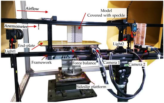
Figure 18.
An overview of the wind tunnel equipped with test platform and morphing wing model.
An in situ stereoscopic DIC system was used to measure the displacement field and the deformation of the trailing edge. The core idea of DIC is to estimate the coordinates and displacements of the full-field speckle pattern by solving an optimization problem based on a typical transfer function model, such as optic flow [49]. By pasting the sticker printed with speckle on the skin of the trailing edge, the shape and deformation can be recorded. Specifically, after the camera calibration, image pre-processing, definition of area of interest (AOI), digital image correlation, and post-processing of the results, the deformation field can be obtained, and the coordinate system transformation and plotting can be realized. Additionally, the average standard deviation of DIC is 0.009 mm.
A six-axis force balance was used to measure the aerodynamic load on the model. For each test condition, the sampling time was 10 s with a sampling frequency of 100 Hz. Then, the aerodynamic loads were obtained with proper coordinate system transformation. The standard deviation of the force balance is 0.096 N; thus, the derived maximum standard deviation of the aerodynamic coefficients is 0.0023.
The turbulence intensity of the wind tunnel is less than 0.25%. The spatial and temporal uncertainty of flow is ±1 m/s; thus, we recorded the results on the anemometer in real time for post-processing. The blockage ratio of the model frontal surface to the test section ranged from 1.5% to 5.38%, depending on different angles of attack and actuation inputs.
4. Aerodynamic Results
This section details the aerodynamic characteristics at various airspeeds, actuation inputs, and angles of attack; moreover, the aerodynamic coefficients are recorded and discussed.
4.1. Aerodynamic Characteristics at Fixed Airspeed
At an airspeed of 25 m/s, the relationship between the aerodynamic characteristics of the mTE4, with different actuation inputs and angles of attack, is shown in Figure 19, including lift, drag, lift-to-drag ratio, polar profile, and pitch moment coefficient with reference point at 30% chord length position. The Reynolds number is about 500,000. The actuation inputs D ranges from −30° to 55° in 12 groups, and the positive inputs actuate the trailing edge deflecting downwards. The angle of attack ranges from −15° to 30°, and a higher sampling density is adopted near the stall angle.
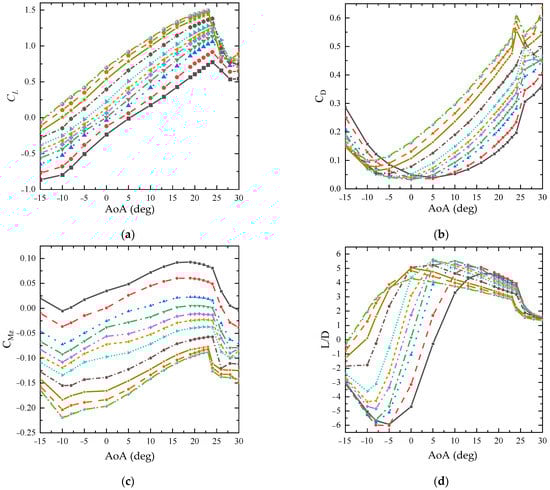
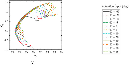
Figure 19.
Aerodynamic characteristics for mTE4 (Airspeed 25 m/s). (a) Lift coefficient. (b) Drag coefficient. (c) Pitch moment coefficient. (d) Efficiency. (e) Polar.
Figure 19a shows the lift coefficients of the mTE4. As the servo actuation input increases, the camber increases, causing the lift coefficient to significantly rise while the slope of the lift line remains roughly the same. Linearity is observed in the range from −10° to 19°, but then nonlinear characteristics are exhibited until stall. A larger camber leads to earlier flow separation (point of separation more upstream), and thus, a smaller stall angle. The maximum lift coefficient is 1.50, obtained with the servo actuation input of 55° and angle of attack of 23°. Furthermore, the variation in the maximum lift coefficient with actuation input is shown in Figure 20a.
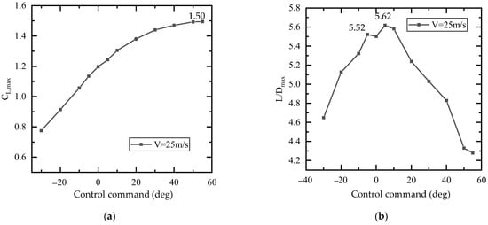
Figure 20.
Maximum lift coefficient and maximum lift-to-drag ratio under different actuation inputs. (a) Maximum lift. (b) Maximum lift-to-drag ratio.
The drag coefficients of the mTE4 are shown in Figure 19b. The airfoil camber increases with increasing actuation input, causing the overall drag curve to shift left, while the minimum drag also increases. This may be because the area that is directly exposed to the wind is larger with a greater camber. For example, when the actuation input is −5°, the mTE4 model reaches the minimum drag of 0.0326 at 0° ; when the deflection input is 55°, the minimum drag coefficient increases to 0.100 at the angle of attack of −10°. In the test, as the angle of attack increases, the drag coefficient first decreases and after reaching the minimum drag coefficient, gradually increases and reaches the local maximum drag at the critical angle. The maximum drag coefficient for this model is 0.613 when the actuation input is 55°, with an angle of attack of 24°. Subsequently, a sudden decrease in the drag coefficient is caused by an abrupt change in the location of the flow separation point and the reattachment of the turbulent shear boundary layer during the stall [50]. When the wing is fully stalled, the drag continues to increase.
Figure 19c demonstrates the pitch moments of the mTE4 with a reference point at the 30% chord length position. The pitch moment curve is directly related to the lift because the aerodynamic center is constant. As the actuation input increases, the curve shifts downwards; consequently, the downward force moment increases. At a 0° angle of attack, the pitch moment coefficient adjustment range of 0.23 can be achieved by camber control at the trailing edge.
The lift-to-drag ratio curves of the mTE4 are shown in Figure 19d. The higher the lift-to-drag ratio, the higher the aerodynamic efficiency. Models with different cambers achieved different maximum lift-to-drag ratios and different angles of attack to obtain the maximum lift-to-drag ratio. The relationship between the maximum lift-to-drag ratio and actuation inputs is shown in Figure 20b. In the negative input range, the maximum lift-to-drag ratio increases with the actuation, and the maximum lift-to-drag ratio is obtained at the actuation input of 5° and angle of attack of 5°. After that, the maximum lift coefficient rapidly decreases with the increase in camber. When the wing stalls, the lift-to-drag ratio sharply decreases, and its trend tends to be the same for different cambers, indicating that camber has a relatively small influence on the aerodynamic characteristics when stall occurs.
There is a maximum upper limit of the lift-to-drag ratio for the given mTE4, called the ‘efficiency envelope [51]’, i.e., there is an optimal trailing edge actuation input at different angles of attack that allows for the mTE4 to achieve the maximum lift-to-drag ratio, as shown in Figure 21a. Then, the relationship between the lift-to-drag ratio and angle of attack is plotted in Figure 21b, following an ‘S-shaped’ curve. For a certain lift coefficient, there is an actuation input that minimizes the drag. This means that under different flight conditions (e.g., changes in vehicle weight resulting in different lift coefficient requirements), the drag coefficient can be minimized, or the lift-to-drag ratio can be increased by active camber morphing [52]. This similar efficiency envelope can also be observed in the polar curves, as shown in Figure 19e.
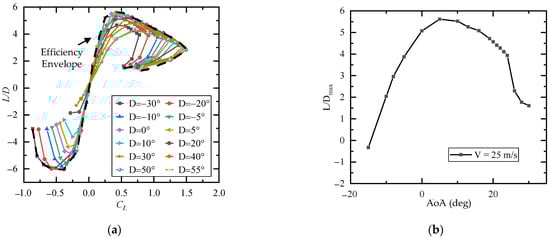
Figure 21.
Efficiency envelope for mTE4 (airspeed 25 m/s). (a) Maximum lift-to-drag ratio for different lift coefficients and actuation inputs. (b) Maximum lift-to-drag ratio for different angles of attack.
4.2. Aerodynamic Characteristics at Various Airspeeds
Extending the wind tunnel test speed to two cases of 10 m/s and 25 m/s, with a chord length of 0.28 m as the reference size, the Reynolds numbers are 200,000 and 500,000, respectively. Figure 22 compares the lift coefficient versus actuation input and angle of attack (AoA) at two airspeeds, in which brighter colors indicate larger values.
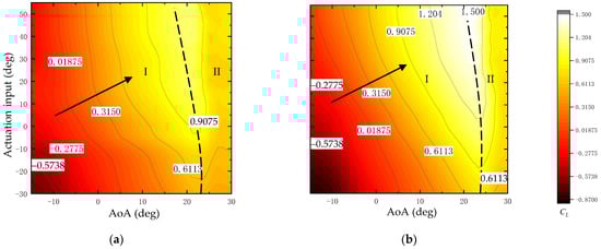
Figure 22.
Lift coefficient versus AoA/actuation input for mTE4 at different airspeeds. (a) Airspeed 10 m/s. (b) Airspeed 25 m/s.
The maximum lift coefficients under each actuation input are connected by a dashed line. The dashed line divides the contour into two regions, left and right, marked as region I and region II, respectively, as shown in Figure 22. In each region, the trend of the lift coefficients with servo actuation inputs and angles of attack is the same for both operating conditions. In region I, the lift coefficient increases as the actuation inputs and angles of attack increase, i.e., in the direction indicated by the arrow. Additionally, when the angle of attack further increases, the turbulence separation point on the upper surface gradually moves from the trailing edge to the leading edge; consequently, the wing starts to stall. The static lift characteristics after stall are shown in region II, where the flow on the upper surface has been completely separated, and the contribution of the camber on the aerodynamic characteristics is relatively small. The difference is that the slope of the lift curve is greater at a high Reynolds number; as the Reynolds number increases, the stall angle of attack increases and the dashed line moves to the right. At a speed of 10 m/s, the maximum lift coefficient is 1.14; when the speed is 25 m/s, the maximum lift increases to 1.50.
With the increase in Reynolds number, the slope of the lift curve and stall angle of attack increase. Several angles of attack were selected to plot the relationship between lift and actuation input at different angles of attack, as shown in Figure 23. The lift increases with the increase in wing camber, and no stall occurs in the full range of actuation inputs. Additionally, the lift coefficient changes faster with actuation inputs at a high airspeed. When the angle of attack is 24° and 26°, the mTE4 stalls at large actuation input angles, and correspondingly the stall angle is greater at a high Reynolds number then that at a low Reynolds number.
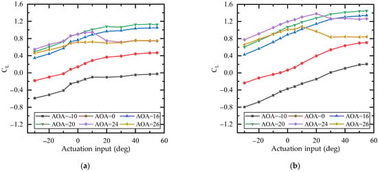
Figure 23.
Lift coefficient versus actuation input for mTE4 at different airspeeds. (a) Airspeed 10 m/s. (b) Airspeed 25 m/s.
At greater wind speeds, the stall angle is greater. This is probably because the separation is due to the fact that the velocity is too low (due to the effect of viscous drag, etc.) and the flow struggles to continue to follow a surface. At greater flow velocities, the Reynolds number and dynamic pressure are greater, i.e., the boundary layer energy is higher. Separation does not occur when the adverse pressure gradient is not greater than a certain threshold, resulting in an easy access to the adverse pressure gradient at low velocities, while, at high velocities, separation is delayed. This can also be seen in the basic method of stall suppression, i.e., injecting energy into the boundary layer, which makes it easier for the airflow to follow a surface when it is accelerated. As for the difference in the influence of trailing edge camber on the stall angle at the two wind speeds, it can be understood that at high speeds, the boundary layer energy easily reaches a sufficient level to maintain the flow, so it is more insensitive to the change in the adverse pressure gradient brought about by the trailing edge camber.
4.3. Comparison and Validation
In this section, we validated the accuracy of the wind tunnel tests by comparing the lift coefficients with numerical results at the freestream velocity of 25 m/s. The deformed wing with 15° downward deflection and the undeformed wing were used.
The comparison between the CFD results and the wind tunnel measurements for the deformed and undeformed wing at −5, 0, 5, 10, 13, and 16° is shown in Figure 24. The two results match well when the angles of attack are small, and the error are generally within 10% or less than 0.04. When the angle of attack increases to more than 10°, the difference between the two results seems to be larger, indicating it is difficult for CFD to predict the transition [53]. In general, good correspondence between the CFD and the experimental lift coefficients validates the accuracy of the experimental results.
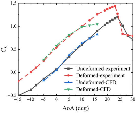
Figure 24.
Comparison of lift curve between numerical and experimental results.
5. Aeroelastic Results
The in situ DIC system measures the trailing edge deformation. The measurement range includes the upper and lower surfaces and the fairing, occupying from 40% of the chord to the end of the trailing edge.
Firstly, the static aeroelastic characteristics of the mTE4 at the airspeed of 15 m/s were studied, and the range of actuation inputs was adjusted from −55° to 55°. The deformation of the upper and lower surfaces is shown in Figure 25. The mTE4 consistently deforms along the spanwise direction, and mainly shows the variation in camber. When the servo actuation input is −55°, the maximum upward displacement of the trailing edge is 39.0 mm, and the equivalent upward deflection angle is 22.2° (based on the chord length of 103 mm covered by the DIC measurement region). The maximum downward displacement achieved is 27.8 mm, with an actuation input of 55°, and the corresponding maximum downward deflection angle is 15.7°. In summary, the mTE4 achieves a trailing edge camber morphing of 37.9° and a chordwise displacement range of 24.4 mm at the lower surface slide.
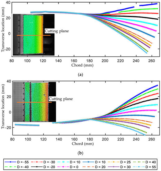
Figure 25.
Deformation at half span (airspeed 15 m/s, AoA 0°). (a) Upper surface. (b) Lower surface.
Experiments were conducted to study the static aeroelastic deformation characteristics of the mTE4 at an airspeed of 10 m/s. The location of the upper surface at the half-span section with or without aerodynamic load is shown in Figure 26 (recorded at the DIC coordinate system) with an actuation input of −30° and an angle of attack of 26°. The white background area is the wing box area, and the gray background is the trailing edge; the black solid line is the deformation without wind, and the red dashed line is the deformation with airspeed of 10 m/s. The trailing edge is slightly deformed with airflow: the lift makes the trailing edge deflect upward and reduces the camber. Furthermore, the transverse deformation difference was obtained by comparing the red dashed line and the black one in Figure 26a, as shown in Figure 26b. In the wing box region, an overall deformation of about 0.1 mm is observed; in the trailing edge region, the deformation gradually increases along the chord until it finally grows to a maximum of 0.7 mm, which is less than 1%. Additionally, the rugged area may be caused by the wrinkle in the adhesive stickers. It should be noted that the appearance of this deformation is also related to the gap caused by the fisheye ball head on the linkage long shaft connection. This allows for the small deformation caused by the aerodynamic load not being constrained by the servo system. To conclude, the variable camber trailing edge developed in this work has a better load-carrying capacity, better environmental adaptability and shape control capability compared with the corrugated-based variable camber trailing edge (e.g., FishBAC [51]).
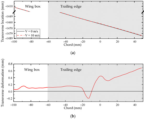
Figure 26.
Static aeroelastic deformation of mTE4 (actuation input −30°, AoA 26°). (a) Transverse location. (b) Transverse deformation.
Figure 27 shows the relationship between the static aeroelastic deformation and the actuation input with angles of attack, by using the transverse deformation difference at the probe point as the indicator. The airspeed is 10 m/s. The deformation is generated by comparing the shape of the trailing edge with and without aerodynamic loads. The probe point is located at the half-span position and 95% of the chord length on the upper surface. The angle of attack measurement ranges from −15° to 30°, and the actuation input range ranges from −30° to +30°. At an angle of attack of −15° and actuation input of −10°, the displacement is the smallest, which is 0.108 mm. At an angle of attack of 26° and actuation input of −30°, the displacement reaches the maximum at 0.568 mm.
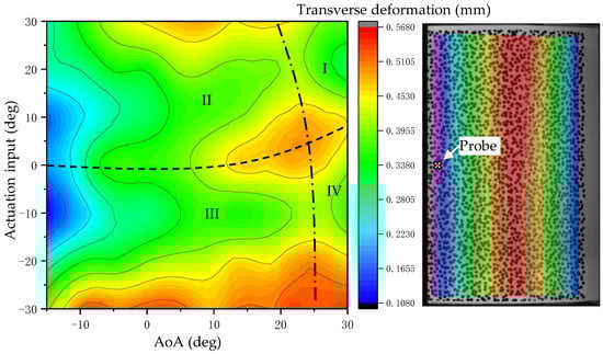
Figure 27.
Static aeroelastic deformation of probe point on mTE4 (Airspeed 10 m/s).
The black dashed and dotted lines divide the region into four quadrants, as shown in Figure 27. In quadrants II and III, the displacement increases with increasing absolute actuation input values and angle of attack; in quadrants I and IV, it decreases with increasing angle of attack. In quadrants II and III, the increase in actuation input angle and angle of attack causes the aerodynamic load to increase; while quadrants I and IV are the post-stall region, the local aerodynamic load also decreases as the airflow separates in the trailing edge.
6. Application in Stall Mitigation
The literature suggests that it is possible to achieve stall mitigation by periodically deflecting the trailing edge [54,55]. In this test, mTE4 was used for stall mitigation with an actuation offset of 20°, amplitudes of 4° and 6°, and frequency range from 1 to 8 Hz. The airspeed was 10 m/s, with a corresponding Reynolds number of about 200,000. The angles of attack ranged from 21° to 28°, covering the entire stall range. The corresponding reduced frequencies are shown in Table 3.
Table 3.
Frequency and corresponding reduced frequency.
The effect of vibration of the trailing edge on the lift coefficient was first tested to exclude the inertial force. As shown in Figure 28, the increment in lift coefficient is less than 0.012, which is about 1% relative to the maximum lift coefficient.
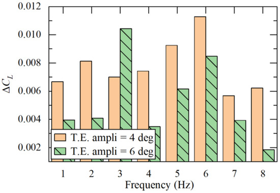
Figure 28.
Effect of trailing edge vibration on force measurement without airflow.
The variation in the lift coefficient near the stall angle with different actuation frequencies is shown in Figure 29, considering the actuation amplitudes of 4 and 6°. The angles of attack are divided into pre-stall, critical, and post-stall states, corresponding to the angle ranges of less than 23°, 23° to 25°, and greater than 25°, respectively. Before stall, the maximum lift coefficient could be increased by 0.03~0.04, which is about 3%. After the stall, the maximum lift coefficient increasement was 0.08, which is about 13%. The critical state has strong unsteady and hysteresis characteristics, and the flow presents separation and reattachment, resulting in large uncertainty. The data in the figures show that trailing edge vibration in this range could increase the lift coefficient by about 0.10~0.22, which is about 16~33%.
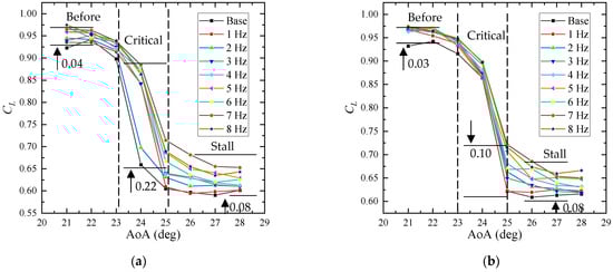
Figure 29.
Lift coefficient of mTE4 at different trailing edge vibration frequencies and amplitudes (airspeed 10 m/s). (a) Vibration amplitude of 4°. (b) Vibration amplitude of 6°.
The variation in the lift coefficient with the actuation frequency is shown in Figure 30. In the test range, the effect of stall mitigation increases with increasing frequency. The data were analyzed as three groups, namely, before stall, critical stall, and after stall, using the linear fitting tool, and the resulting fitted curves are shown as black dashed lines in Figure 30. Anomalies are excluded in the linear fitting. Before the stall, the slopes in the lift coefficient versus frequency are 0.0044/Hz and 0.0026/Hz, corresponding to the servo actuation input amplitudes of 4° and 6°, respectively.
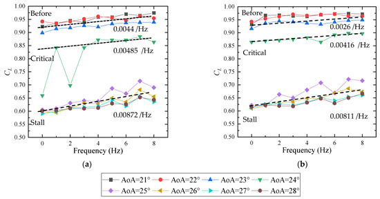
Figure 30.
Lift coefficient versus frequency for different angles of attack (airspeed 10 m/s). (a) Vibration amplitude of 4°. (b) Vibration amplitude of 6°.
As the angle of attack increases, trailing edge vibration leads to a more significant lift increment. At the critical angle, the slope of the lift coefficient with respect to frequency increases to 0.00485/Hz and 0.00416/Hz, respectively. After stall, the increase in vibration frequency has a greater effect on the lift coefficient, and the slope of the lift coefficient with respect to frequency increases to 0.00872/Hz and 0.00811/Hz, respectively.
7. Conclusions
In this article, a compliant morphing wing (named mTE4) featuring a novel, load-bearing morphing trailing edge was introduced and tested. The aerodynamic and structural profile of the wing was obtained from a numerical optimization-based methodology utilizing a multi-disciplinary approach in the previous work. With a comprehensive detailed design of actuator and sensor systems, the mTE4 was developed and manufactured. Then, a wind tunnel test was conducted to evaluate the aerodynamic and aeroelastic behavior of this novel device. Furthermore, the possibility of stall mitigation using an actively vibrating trailing edge was verified. Finally, a validation study was carried out to assess the accuracy of the experimental procedure. The main contributions are summarized as follows:
- The proposed morphing wing concept is manufacturable. Under actuation, the skin length of the trailing edge upper surface remains constant, and the lower surface is allowed to slide into the wing box, solving the challenge of skin continuity during the deformation process;
- The novel wing concept is actuated by a traditional servo system, while the aim of smoothing deformation is achieved by compliant mechanisms. The manufactured morphing wing can achieve a maximum deflection range of 37.9° continuously, proving its morphing capacity. The model operates as expected, demonstrating robustness and load-bearing ability;
- By activating the actuators, variations in lift coefficient ∆CL ≈ 0.23 and pitch moment coefficient ∆CMz ≈ 0.22 in various angles of attack at 25 m/s can be achieved;
- Different wind speeds lead to different Reynolds numbers, which affect the test results. As the airspeed increases, the airflow is less likely to separate from the upper surface of the wing, resulting in increments in the maximum lift coefficient, the stall angle, and the lift curve slope;
- Stall mitigation is achieved by periodically deflecting the morphing trailing edge, enabling a stall angle delay of approximately 1° and 13% increase in post-stall lift coefficient;
- Good correspondence between the CFD and the experimental lift coefficients validates the effectiveness of the development procedure.
However, mTE4 deforms along the chordwise but not spanwise direction. In this case, only segmental control of the wing can be achieved by slitting between adjacent variable camber trailing edges, which goes against the original design intent of a full, continuous, smooth deformation. Without spanwise transition abilities, the application of morphing trailing edges in the aircraft industry would be of limited significance. Therefore, in future work, we aim to extend the compliant mechanism to wing with chordwise–spanwise trailing edge deformation.
Author Contributions
Conceptualization, Z.Z., S.J. and C.S.; methodology, Z.Z. and S.J.; software, S.J. and Z.Z.; validation, S.J. and Z.Z.; formal analysis, S.J.; investigation, S.J. and Z.Z.; resources, S.J. and Z.Z.; data curation, S.J. and Z.Z.; writing—original draft preparation, S.J.; writing—review and editing, Z.Z., H.Z., C.S. and C.Y.; visualization, S.J. and Z.Z.; supervision, C.S. and C.Y.; project administration, C.S. and C.Y. All authors have read and agreed to the published version of the manuscript.
Funding
This research was funded by National Natural Science Foundation of China (grant number 11402013).
Institutional Review Board Statement
Not applicable.
Informed Consent Statement
Not applicable.
Data Availability Statement
The data presented in this study are available on request from the corresponding author.
Acknowledgments
Sijia Jia wishes to thank Yuting Dai and Chaoyuan Wen for their support and advice. Zhenkai Zhang would like to thank his promotors, Sergio Ricci and Alessandro De Gaspari, for their encouragement and enlightenment.
Conflicts of Interest
The authors declare no conflict of interest.
References
- Wang, B.; Yang, Y.; Qian, Z.; Wang, Z.; Lyu, S.; Sun, X. Technical development of variable camber wing: Review. Acta Aeronaut. Astronaut. Sin. 2022, 43, 024943. [Google Scholar] [CrossRef]
- Barbarino, S.; Bilgen, O.; Ajaj, R.M.; Friswell, M.I.; Inman, D.J. A Review of Morphing Aircraft. J. Intell. Mater. Syst. Struct. 2011, 22, 823–877. [Google Scholar] [CrossRef]
- Chu, L.; Li, Q.; Gu, F.; Du, X.; He, Y.; Deng, Y. Design, Modeling, and Control of Morphing Aircraft: A Review. Chin. J. Aeronaut. 2021, 35, 220–246. [Google Scholar] [CrossRef]
- Ajaj, R.M.; Parancheerivilakkathil, M.S.; Amoozgar, M.; Friswell, M.I.; Cantwell, W.J. Recent Developments in the Aeroelasticity of Morphing Aircraft. Prog. Aerosp. Sci. 2021, 120, 100682. [Google Scholar] [CrossRef]
- Monner, H.P. Realization of an Optimized Wing Camber by Using Formvariable Flap Structures. Aerosp. Sci. Technol. 2001, 5, 445–455. [Google Scholar] [CrossRef]
- Wang, A.D.P.; Bartley-Cho, J.D.; Martin, C.A.; Hallam, B.J. Development of High-Rate Large-Deflection Hingeless Trailing-Edge Control Surface for the Smart Wing Wind Tunnel Model. In Proceedings of the SPIE’s International Symposium on Smart Structures and Materials, Newport Beach, CA, USA, 4–8 March 2001; pp. 407–418. [Google Scholar]
- Campanile, L.F.; Sachau, D. Belt-Rib Concept: A Structronic Approach to Variable Camber. J. Intell. Mater. Syst. Struct. 2000, 11, 215–224. [Google Scholar] [CrossRef]
- Woods, B.K.S.; Friswell, M.I. Preliminary Investigation of a Fishbone Active Camber Concept. In Proceedings of the ASME 2012 Conference on Smart Materials, Adaptive Structures and Intelligent System, Stone Mountain, GA, USA, 19–21 September 2012; Volume 2, pp. 555–563. [Google Scholar] [CrossRef]
- Hetrick, J.; Osborn, R.; Kota, S.; Flick, P.; Paul, D. Flight Testing of Mission Adaptive Compliant Wing. In Proceedings of the 48th AIAA/ASME/ASCE/AHS/ASC Structures, Structural Dynamics, and Materials Conference, Honolulu, HI, USA, 23–26 April 2007; American Institute of Aeronautics and Astronautics: Reston, VA, USA, 2007; pp. 1–17. [Google Scholar]
- Wild, J. Recent Research Topics in High-Lift Aerodynamics. CEAS Aeronaut. J. 2016, 7, 345–355. [Google Scholar] [CrossRef]
- Li, D.; Guo, S.; Xiang, J. Modeling and Nonlinear Aeroelastic Analysis of a Wing with Morphing Trailing Edge. Proc. Inst. Mech. Eng. Part G J. Aerosp. Eng. 2013, 227, 619–631. [Google Scholar] [CrossRef]
- Steenhuizen, D.; Van Tooren, M. The Implementation of a Knowledge-Based Framework for the Aerodynamic Optimization of a Morphing Wing Device. Adv. Eng. Inform. 2012, 26, 207–218. [Google Scholar] [CrossRef]
- Guo, S.; Li, D.; Liu, Y. Multi-Objective Optimization of a Composite Wing Subject to Strength and Aeroelastic Constraints. Proc. Inst. Mech. Eng. Part G J. Aerosp. Eng. 2012, 226, 1095–1106. [Google Scholar] [CrossRef]
- Barbarino, M.; Dimino, I.; Carozza, A.; Nae, C.; Stoica, C.; Pricop, V.; Peng, S.H.; Eliasson, P.; Grundestam, O.; Tysell, L.; et al. Airframe Noise Reduction Technologies Applied to High-Lift Devices of Future Green Regional Aircraft. In Proceedings of the 3AF/CEAS Conference “Greener Aviation: Clean Sky Breakthroughs and Worldwide Status”, Brussel, Belgium, 12–14 March 2014; HAL: Brussel, Belgium, 2014; Volume hal-010821, pp. 1–11. [Google Scholar]
- Hellstrom, T. The Clean Sky “Smart Fixed Wing Aircraft Integrated Technology Demonstrator”: Technology Targets and Project Status. In Proceedings of the 27th Congress of the International Council of the Aeronautical Sciences 2010, ICAS 2010, Nice, France, 19–24 September 2010; Volume 6, pp. 5101–5110. [Google Scholar]
- Broughton-Venner, J.J.; Wynn, A.; Palacios, R. Aeroservoelastic Optimisation of an Aerofoil with Active Compliant Flap via Reparametrisation and Variable Selection. In Proceedings of the 58th AIAA/ASCE/AHS/ASC Structures, Structural Dynamics, and Materials Conference, Grapevine, TX, USA, 9–13 January 2017; American Institute of Aeronautics and Astronautics: Reston, VA, USA, 2017; pp. 1–20. [Google Scholar]
- Nickol, C.L.; Haller, W.J. Assessment of the Performance Potential of Advanced Subsonic Transport Concepts for NASA’s Environmentally Responsible Aviation Project. In Proceedings of the 54th AIAA Aerospace Sciences Meeting, San Diego, CA, USA, 4–8 January 2016; Volume F, pp. 1–21. [Google Scholar]
- Miller, E.J.; Cruz, J.; Lung, S.; Kota, S.; Ervin, G.; Lu, K.-J.; Flick, P. Evaluation of the Hinge Moment and Normal Force Aerodynamic Loads from a Seamless Adaptive Compliant Trailing Edge Flap in Flight. In Proceedings of the 54th AIAA Aerospace Sciences Meeting, San Diego, CA, USA, 4–8 January 2016. [Google Scholar]
- Woods, B.K.S.; Parsons, L.; Coles, A.B.; Fincham, J.H.S.; Friswell, M.I. Morphing Elastically Lofted Transition for Active Camber Control Surfaces. Aerosp. Sci. Technol. 2016, 55, 439–448. [Google Scholar] [CrossRef]
- Woods, B.K.S.; Dayyani, I.; Friswell, M.I. Fluid/Structure-Interaction Analysis of the Fish-Bone-Active-Camber Morphing Concept. J. Aircr. 2015, 52, 307–319. [Google Scholar] [CrossRef]
- Ting, E.; Chaparro, D.; Nguyen, N.; Fujiwara, G.E.C. Optimization of Variable-Camber Continuous Trailing-Edge Flap Configuration for Drag Reduction. J. Aircr. 2018, 55, 2217–2239. [Google Scholar] [CrossRef]
- Vasista, S.; Riemenschneider, J.; van de Kamp, B.; Monner, H.P.; Cheung, R.C.M.; Wales, C.; Cooper, J.E. Evaluation of a Compliant Droop-Nose Morphing Wing Tip via Experimental Tests. J. Aircr. 2017, 54, 519–534. [Google Scholar] [CrossRef]
- Rudenko, A.; Hannig, A.; Monner, H.P.; Horst, P. Extremely Deformable Morphing Leading Edge: Optimization, Design and Structural Testing. J. Intell. Mater. Syst. Struct. 2018, 29, 764–773. [Google Scholar] [CrossRef]
- Wölcken, P.C.; Papadopoulos, M. Smart Intelligent Aircraft Structures (SARISTU); Wölcken, P.C., Papadopoulos, M., Eds.; Springer International Publishing: Hamburg, Germany, 2016; pp. 1–1025. [Google Scholar]
- Henry, A.C.; Molinari, G.; Rivas-Padilla, J.R.; Arrieta, A.F. Smart Morphing Wing: Optimization of Distributed Piezoelectric Actuation. AIAA J. 2019, 57, 2384–2393. [Google Scholar] [CrossRef]
- Keidel, D.; Molinari, G.; Ermanni, P. Aero-Structural Optimization and Analysis of a Camber-Morphing Flying Wing: Structural and Wind Tunnel Testing. J. Intell. Mater. Syst. Struct. 2019, 30, 908–923. [Google Scholar] [CrossRef]
- Radestock, M.; Riemenschneider, J.; Monner, H.P.; Huxdorf, O.; Werter, N.P.M.; De Breuker, R. Deformation Measurement in the Wind Tunnel for an UAV Leading Edge with a Morphing Mechanism. In Proceedings of the 30th Congress of the International Council of the Aeronautical Sciences, Daejeon, Korea, 25–30 September 2016; pp. 1–9. [Google Scholar]
- Riemenschneider, J.; Radestock, M.; Vasista, S.; Huxdorf, O.; Monner, H.P. Droop Nose with Elastic Skin. In Proceedings of the ASME 2016 Conference on Smart Materials, Adaptive Structures and Intelligent Systems, Stowe, VT, USA, 28–30 September 2016; ASME: Stowe, VT, USA, 2016; pp. 1–8. [Google Scholar]
- Dimino, I.; Moens, F.; Pecora, R.; Ricci, S.; Ameduri, S.; Concilio, A.; Mercurio, U.; Carossa, G.M. Morphing Wing Technologies within the Airgreen 2 Project. AIAA Sci. Technol. Forum Expo. AIAA SciTech Forum 2022, 2022, 0718. [Google Scholar] [CrossRef]
- Pecora, R. Morphing Wing Flaps for Large Civil Aircraft: Evolution of a Smart Technology across the Clean Sky Program. Chin. J. Aeronaut. 2021, 34, 13–28. [Google Scholar] [CrossRef]
- Mkhoyan, T.; Thakrar, N.R.; De Breuker, R.; Sodja, J. Design and Development of a Seamless Smart Morphing Wing Using Distributed Trailing Edge Camber Morphing for Active Control. In Proceedings of the AIAA Scitech 2021 Forum, Virtual Event, 11–15 & 19–21 January 2021; pp. 1–16. [Google Scholar]
- Simiriotis, N.; Jodin, G.; Marouf, A.; Elyakime, P.; Hoarau, Y.; Hunt, J.C.R.; Rouchon, J.F.; Braza, M. Morphing of a Supercritical Wing by Means of Trailing Edge Deformation and Vibration at High Reynolds Numbers: Experimental and Numerical Investigation. J. Fluids Struct. 2019, 91, 102676. [Google Scholar] [CrossRef]
- Howell, L.L. Compliant Mechanisms; John Wiley: New York, NY, USA, 2001; ISBN 0-471-38478-X. [Google Scholar]
- Herrera, C.; Spivey, N.; Lung, S.; Ervin, G.; Flick, P. Aeroelastic Response of the ACTE Transition Section. In Proceedings of the 57th AIAA/ASCE/AHS/ASC Structures, Structural Dynamics, and Materials Conference, San Diego, CA, USA, 4–8 January 2016; pp. 1–19. [Google Scholar]
- Saggere, L.; Kota, S. Static Shape Control of Smart Structures Using Compliant Mechanisms. AIAA J. 1999, 37, 572–578. [Google Scholar] [CrossRef]
- Kota, S.; Flick, P.; Collier, F.S. Flight Testing of FlexFloil TM Adaptive Compliant Trailing Edge. In Proceedings of the 54th AIAA Aerospace Sciences Meeting, San Diego, CA, USA, 4–8 January 2016. [Google Scholar]
- De Gaspari, A.; Ricci, S. A Two-Level Approach for the Optimal Design of Morphing Wings Based On Compliant Structures. J. Intell. Mater. Syst. Struct. 2011, 22, 1091–1111. [Google Scholar] [CrossRef]
- De Gaspari, A.; Riccobene, L.; Ricci, S. Design, Manufacturing and Wind Tunnel Validation of a Morphing Compliant Wing. J. Aircr. 2018, 55, 2313–2326. [Google Scholar] [CrossRef]
- Zhang, Y.; Ge, W.; Zhang, Z.; Mo, X.; Zhang, Y. Design of Compliant Mechanism-Based Variable Camber Morphing Wing with Nonlinear Large Deformation. Int. J. Adv. Robot. Syst. 2019, 16, 1729881419886740. [Google Scholar] [CrossRef]
- Zhang, Z.; De Gaspari, A.; Ricci, S.; Song, C.; Yang, C. Gradient-Based Aerodynamic Optimization of an Airfoil with Morphing Leading and Trailing Edges. Appl. Sci. 2021, 11, 1929. [Google Scholar] [CrossRef]
- Olson, E.D. Three-Dimensional Piecewise-Continuous Class-Shape Transformation of Wings. In Proceedings of the Multidisciplinary Analysis and Optimization Conference, Dallas, TX, USA, 22–26 June 2015; pp. 1–16. [Google Scholar]
- Hardy, R.L. Theory and Applications of the Multiquadric-Biharmonic Method 20 Years of Discovery 1968-1988. Comput. Math. Appl. 1990, 19, 163–208. [Google Scholar] [CrossRef]
- SU2 v7.4.0 Blackbird. Available online: https://su2code.github.io/ (accessed on 10 August 2022).
- Eiter, T.; Mannila, H. Computing Discrete Fréchet Distance; Citeseer: Princeton, NJ, USA, 1994. [Google Scholar]
- Molinari, G. Multidisciplinary Optimization of Morphing Wings with Distributed Compliance and Smart Actuation. Ph.D. Thesis, ETH Zurich, Zurich, Switzerland, 2016. [Google Scholar]
- Zhang, Z.; Jia, S.; Song, C.; Yang, C. Optimum design of wind tunnel test model for compliant morphing trailing edge. Acta Aeronaut. Astronaut. Sin. 2021, 43, 026071. [Google Scholar] [CrossRef]
- Shenzhen Wenext Technology Co., Ltd. Material Manual. 2021. Available online: https://www.wenext.cn/index.php?route=product/material/view&material_id=27 (accessed on 8 August 2022).
- Schreier, H.; Orteu, J.J.; Sutton, M.A. Image Correlation for Shape, Motion and Deformation Measurements: Basic Concepts, Theory and Applications; Springer: New York, NY, USA, 2009; ISBN 9780387787466. [Google Scholar]
- Bigger, R.; Blaysat, B.; Boo, C.; Grewer, M.; Hu, J.; Jones, A.; Klein, M.; Raghavan, K.; Reu, P.; Schmidt, T.; et al. A Good Practices Guide for Digital Image Correlation; Jones, E., Iadicola, M., Eds.; Springer: Berlin/Heidelberg, Germany, 2018. [Google Scholar]
- Tank, J.D.; Klose, B.F.; Jacobs, G.B.; Spedding, G.R. Flow Transitions on a Cambered Airfoil at Moderate Reynolds Number. Phys. Fluids 2021, 33, 093105. [Google Scholar] [CrossRef]
- Woods, B.K.; Bilgen, O.; Friswell, M.I. Wind Tunnel Testing of the Fish Bone Active Camber Morphing Concept. J. Intell. Mater. Syst. Struct. 2014, 25, 772–785. [Google Scholar] [CrossRef]
- Rivero, A.E.; Fournier, S.; Manolesos, M.; Cooper, J.E.; Woods, B.K.S.S. Experimental Aerodynamic Comparison of Active Camber Morphing and Trailing-Edge Flaps. AIAA J. 2021, 59, 2627–2640. [Google Scholar] [CrossRef]
- Rogers, S.E.; Roth, K.; Cao, H.V.; Slotnick, J.P.; Whitlock, M.; Nash, S.M.; David Baker, M. Computation of Viscous Flow for a Boeing 777 Aircraft in Landing Configuration. In Proceedings of the 18th Applied Aerodynamics Conference, Denver, CO, USA, 14–17 August 2000; pp. 1–11. [Google Scholar] [CrossRef]
- Kan, Z.; Li, D.; Xiang, J.; Cheng, C. Delaying Stall of Morphing Wing by Periodic Trailing-Edge Deflection. Chin. J. Aeronaut. 2020, 33, 493–500. [Google Scholar] [CrossRef]
- Jodin, G.; Motta, V.; Scheller, J.; Duhayon, E.; Döll, C.; Rouchon, J.F.; Braza, M. Dynamics of a Hybrid Morphing Wing with Active Open Loop Vibrating Trailing Edge by Time-Resolved PIV and Force Measures. J. Fluids Struct. 2017, 74, 263–290. [Google Scholar] [CrossRef]


Publisher’s Note: MDPI stays neutral with regard to jurisdictional claims in published maps and institutional affiliations. |
© 2022 by the authors. Licensee MDPI, Basel, Switzerland. This article is an open access article distributed under the terms and conditions of the Creative Commons Attribution (CC BY) license (https://creativecommons.org/licenses/by/4.0/).