Article

Jet Mixings of Alternating-Lobe Nozzles under Pumping Air Intake and Stamping Air Intake Conditions

1
School of Aircraft Engineering, Nanchang Hangkong University, Nanchang 330063, China
2
Jiangxi Key Laboratory of Aircraft Design and Aerodynamic Simulation, Nanchang Hangkong University, Nanchang 330063, China
*
Author to whom correspondence should be addressed.
Aerospace 2022, 9(11), 700; https://doi.org/10.3390/aerospace9110700
Submission received: 20 September 2022 / Revised: 1 November 2022 / Accepted: 1 November 2022 / Published: 9 November 2022
(This article belongs to the Section Aeronautics)

Abstract

:
Jet mixings of a coplanar alternating-lobe nozzle (CoALN), scarfing alternating-lobe nozzle (ScALN), sword alternating-lobe nozzle (SwALN), and sword and chevron alternating-lobe nozzle (SwChALN) were numerically investigated using three different far-field velocities to simulate the conditions of pumping air intake and stamping air intake. It was confirmed that the stamping air intake can be introduced to increase the cool air involved in the mixing for an infrared suppressor of a helicopter. It was found that the stamping air intake increases the amount of cool stream near the mixing tube, which can effectively decrease the temperature of the mixing tube, thus improving the infrared suppression performance. Under the two intake conditions, for a normal infrared suppressor with a short mixing tube, SwALN and SwChALN are recommended; however, for an integrated infrared suppressor with a long mixing tube, CoALN and ScALN should be adopted. The shape of the longitudinal vortices is closely related to the large-scale heat and mass convection. The plumper longitudinal vortices can bring faster mixing to the affected region.

1. Introduction

Stealth technology is an effective means for a military equipment to improve survivability and achieve higher combat effectiveness. For example, Khan et al. [1] studied the enhancement of supersonic jet mixing by using rectangular tabs, Singh et al. [2] studied cooling the duct by injecting air from the environment, Zhou et al. [3] studied the V-shaped nozzle with a rectangular cross-section for combat aircraft, Chen et al. [4] studied the cooling bypass outside the turbojet engine, and Mirjalily [5] studied the supersonic nozzle with elliptical cross-section. These studies are helpful to suppress the infrared radiation of the military equipment. The stealth technology of a military helicopter mainly includes reducing noise propagation, suppressing infrared radiation, and reducing radar reflection [6,7,8,9]. For the fixed wing aircraft with the turbofan engine as a power unit, the cool airflow of the bypass can be utilized to suppress the infrared radiation caused by the engine. Shan et al. [10] studied the suppression of infrared radiation of the turbofan engine by cooling the center body with the bypass airflow. Cheng et al. [11,12] studied the infrared radiation of the core and bypass flow of a turbofan engine after mixing in different S-bends with rectangular exits.
The lobed geometry can be introduced to enhance the mixing of coflow fluids. Williams et al. [13] pointed out that, for a scramjet combustor, it is necessary to study the use of lobed structure to inject fuel into supersonic flow. Santana et al. [14] studied the combustion flow of a strut with a lobed trailing edge in a scramjet combustor. Thus, the mixing of the core and bypass flow in a turbofan engine can be enhanced by introducing a lobed nozzle [15,16,17,18]. Du et al. [19] studied the enhancement of the mixing of the core and bypass flow of a turbofan engine in the S-bend by employing a lobed nozzle. However, for the power unit without bypass, a lobed nozzle can be adopted to pump ambient cool air and rapidly mix with the hot exhaust [20,21]. The turboshaft engine is usually used as the power unit for a military helicopter, and there is no bypass for the turboshaft engine; therefore, the infrared suppressor of a military helicopter uses the lobed nozzle to pump cool air from the outside and mix with the hot exhaust of the turboshaft engine [22,23,24]. Usually, the exit of the lobed nozzle is downstream of the center cone for the infrared suppressor. In this case, it is difficult for the ambient cool air to penetrate into the core of the hot exhaust if the conventional circular lobed nozzle is adopted. To solve this problem, Liu [25] proposed to add a central plug cone at the exit of the lobed nozzle. The scarfing alternating-lobe nozzle (ScALN) in a turbofan engine studied by Koutmos et al. [26] and the coplanar alternating-lobe nozzle (CoALN) in a turbojet engine proposed by Presz Jr. [27] can also be used to solve this problem.
When the helicopter hovers, it relies on the hot exhaust of the turboshaft engine to pump the cool air from the outside. When the helicopter flies forward, the stamping air intake can be utilized to increase the cool air involved in the mixing. For example, the ambient air intake of the infrared suppressor on the Eurocopter Tiger is a forward-facing arrangement that can be acted as the stamping air intake. Yang et al. [28] also found that, compared with the hovering state, the infrared radiation intensity of the helicopter is lower in cruise. In previous studies, in view of the infrared suppressor with the pumping air intake, a sword alternating-lobe nozzle (SwALN) was created, which can achieve a high mixing efficiency in a short distance [29,30]; nail-like spoilers [30,31], lobed spoilers [31], and chevron spoilers [32], were proposed to be located at the lobe crests for improving the mixing performance; furthermore, several novel configurations that can enhance the mixing in the core region of SwALN were constructed to obtain an extreme mixing efficiency [33]. In order to compare with the SwALN, three kinds of alternating-lobe nozzles were produced, including a CoALN, ScALN, and sword and chevron alternating-lobe nozzle (SwChALN). In this study, jet mixings of the SwALN, CoALN, ScALN, and SwChALN were numerically investigated using three different far-field velocities to simulate the conditions of pumping air intake and stamping air intake.

2. Geometrical Configurations

Figure 1 shows the jet mixing model of a CoALN with an annular entrance formed by two circles with diameters of 210 and 400 mm. Through a 262.5-mm long cone, the annular section is smoothly transformed to circular with 550-, 293.7-, and 150-mm diameter circles at the lobe crests, shallow valleys, and deep valleys, respectively, giving an outward lobe penetration angle of 12.1°. The distance from the entrance to exit is 600 mm, and the exit has an equivalent diameter d of 400 mm. The mixing tube is 1150 mm long and has an entrance that is 100 mm ahead of the nozzle exit. The diameter D of the tube is 700 mm, which gives a 1.5 length-to-diameter ratio (L/D) for the mixing segment.
Figure 2a–c present a ScALN, SwALN, and SwChALN, respectively. The SwChALN is produced by removing part of the lobe valley and sidewalls of the normal lobed nozzle (NLN) shown in Figure 2d, which has a scarfing angle of 40°, and then smoothly extending the sword spoilers from wide valleys and chevron spoilers from narrow valleys. In contrast, the SwALN is achieved by extending only the sword spoilers from the wide valleys. For all the alternating-lobe nozzles investigated here, the locations and penetration angles of the lobe crests, the diameters of the circles at the deep valleys, and the angles between the sidewalls were maintained as the same. The exception was SwChALN, where the diameters of the circle at the shallow valleys were equal, and the equivalent diameters at the exits were kept close to each other. The locations and penetration angles of the shallow valleys in both ScALN and SwALN were equal. In the case of the SwChALN, the diameter of the circle at the shallow valleys was 256.3 mm, and the equivalent diameter at the exit was the smallest of the nozzles studied. The detailed dimensions of these lobed nozzles are provided in Figure 1 and Figure 2.

3. Numerical Simulation Method

The simulation domain used, which was discretized by tetrahedral cells, is shown in Figure 3a. Figure 3b shows the mesh model of the ScALN, in which three-layer prism cells with a first layer height of 0.05 mm were generated as the boundary cells. The simulation results show that the maximum value of Y+ was less than 2.5 at the far-field velocities of 0 and 25 m/s, and less than 4 at the far-field velocity of 50 m/s. As indicated by the arrow in Figure 3a, a refinement domain was employed wherever drastic changes in the velocity and temperature occurred. The maximum size of the cells in this domain was set to 15 mm. Accordingly, the number of cells in the refinement domain was more than 20 million, whereas the number outside the domain was approximately 2.2 million.
The simulation was performed using FLUENT software and the SST kω turbulence model. A SIMPLE algorithm was used to solve the pressure–velocity coupling, with all convection terms being discretized by the second-order schemes. The boundary conditions are shown in Figure 3a. A velocity of 125 m/s, temperature of 850 K, and turbulent intensity of 5% were assigned to the jet inlet (the magnitude of the Reynolds number was based on the equivalent diameter d and jet conditions of ~2 × 10⁶). The inlet velocity and outlet pressure were set to far-field values, namely, an operating pressure of 10,1325 Pa, temperature of 300 K, and turbulent intensity of 5%. The far-field velocities were 0, 25, and 50 m/s.
The numerical simulation method adopted in this study had been validated in previous studies [31,32,35] by comparing the simulated results with the experimental results reported by Hu et al. [36], as shown in Figure 4 and Figure 5. It can be seen that, in the numerical simulation, compared with results from Realizable kε turbulence model, the results of SST kω turbulence model are more consistent with the experimental results in the core region and region off the lobe crests. At the same time, the variation of the longitudinal vorticity obtained from the SST kω turbulence model is also basically consistent with that of the experiment. Corresponding to the grid independence, the maximum size of the cells in the refinement domain had also been determined in [31,32,35]. The maximum sizes of the cells used in the refinement domains of SwALN were 20, 15, and 12 mm. It was found that the number of cells in the simulation domain increases sharply as the maximum size decreases. When the maximum size was set to 15 mm, the number of cells was still quite reasonable, but the temperature isosurface obtained was similar to that obtained with the maximum size of 12 mm in every region. Therefore, a maximum size of 15 mm was adopted in the refinement domain for the four lobed nozzles in this study.

4. Results and Discussion

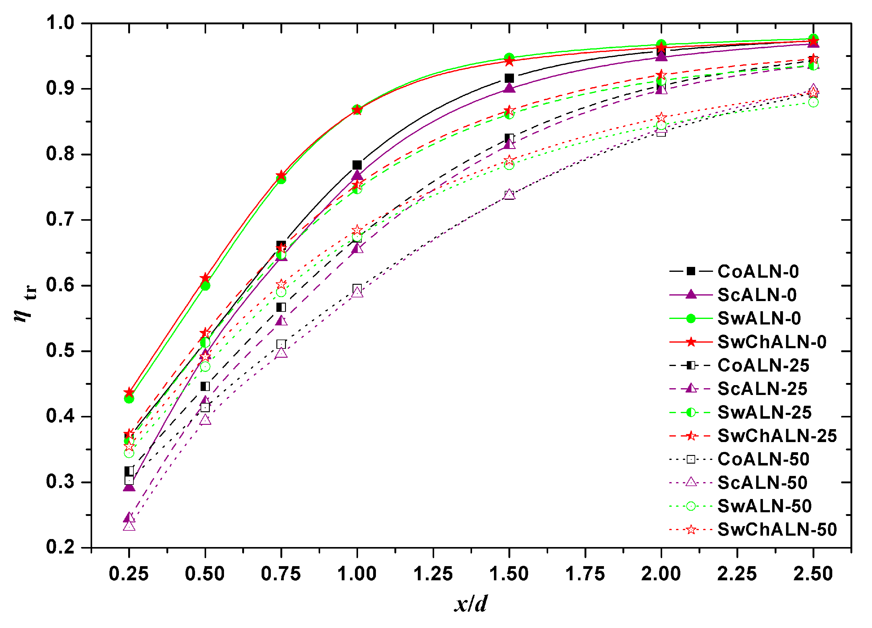
4.1. Jet Mixing Performance

The mass flux ratio Φ is defined as:
Φ = m c / m h
where mh is the mass flux of the hot stream, and mc is the mass flux of the cool stream. The mass flux ratios for each alternating-lobe nozzle at three far-field velocities are given in Table 1. It can be seen that, for each alternating-lobe nozzle, when the far-field velocity is 0 m/s, the mass flux ratio is about 1.1; when the far-field velocity is 25 m/s, the mass flux ratio increases to about 1.6; when the far-field velocity increases to 50 m/s, the mass flux ratio reaches more than 2.6. This confirms that the stamping air intake can be introduced to increase the cool air involved in the mixing.
The thermal mixing efficiency ηtr [37] can be expressed as:
η tr = 1 ( T m T M ) 2 d m m T h 2 m h + T c 2 m c T M 2 m m
Here, mm is the mass flux of the local mixing stream, Th is the temperature of the hot stream, Tc is the temperature of the cool stream, Tm is the temperature of the local mixing stream, and TM is the temperature after complete mixing of the hot and cool streams:
T M = T h m h + T c m c m m
In Figure 6, the thermal mixing efficiency is plotted against x/d for each alternating-lobe nozzle at three far-field velocities, where x represents the axial distance measured from the trailing edge of the CoALN. Figure 7 and Figure 8, respectively, show the 700-K temperature iso-surfaces and temperature distributions at 1.5d for each alternating-lobe nozzle at three far-field velocities. The distribution of the hot stream shown here can be used to explain the thermal mixing efficiency trend evident in Figure 6.
It can be seen in Figure 7 and Figure 8 that, with each alternating-lobe nozzle and an increase in the far-field velocity, a decrease in the outwards penetration angle of the hot stream in the region off the lobe crests is observed (i.e., the downstream region of the lobe crests). Furthermore, there is an increase in the unmixed cool stream near the mixing tube, whereas the mixing speed is unchanged in the region off the sidewalls aside from a slight slowdown in the region off the lobe crests. However, mixing is increased in the core region of CoALN and ScALN, and decreased in the core region of SwALN and SwChALN that is accompanied by a slight increase in the complete-mixing distance. As the far-field velocity increases from 0 to 25 m/s, the mixing speed remains unchanged in the region between the deep and shallow valleys, and increases when the far-field velocity increases from 25 to 50 m/s.
As shown in Figure 6, the thermal mixing efficiency of each alternating-lobe nozzle increases with mixing and approaches one of three specific values depending on the far-field velocity. That is, as the far-field velocity is increased, the thermal mixing efficiency of each alternating-lobe nozzle decreases within the same section. This decrement increases slightly from 0.25d to 1.0d and decreases gradually between 1.5d and 2.5d, revealing that mixing at the anterior segment is slowed, and the proportion of mixing at the posterior segment is enhanced. The greater decrease from 0.25d to 1.0d is primarily owing to an increase in mc, which brings the value of TM closer to that of Tc. When the far-field velocity is accelerated from 0 to 25 m/s, the smaller decrease between 1.5d and 2.5d is most pronounced between 2.0d and 2.5d, the reason being that there is an increase in mixing due to a decrease in the hot stream off the lobe crests impinging the mixing tube (Figure 8).
For each of the three far-field velocities, the thermal mixing efficiency of SwALN and SwChALN is higher than in CoALN and ScALN for the same section from 0.25d to 1.5d, which can be attributed to the significantly higher mixing speed in the regions off the sidewalls and between the deep and shallow valleys with SwALN and SwChALN (Figure 7). After 2.0d, the thermal mixing efficiency of the different alternating-lobe nozzles gradually becomes similar, which indicates that mixing is basically complete before 2.0d is reached except in the core regions (Figure 7 and Figure 8).
The total pressure recovery coefficient σ is defined as:
σ = P m * d m m P h * d m h + P c * d m c
where P h * is the total pressure of the hot stream, P c * is the total pressure of the cool stream, and P m * is the total pressure of the local mixing stream. Figure 9 shows the total pressure recovery coefficients along the axis of each alternating-lobe nozzle at three far-field velocities. It can be observed that the total pressure recovery coefficient decreases during mixing, but for each alternating-lobe nozzle, the value is highest for every given section at a far-field velocity of 25 m/s and lowest at 0 m/s. Furthermore, the decrease in total pressure recovery coefficient from 0.25d to 2.5d is the greatest with a far-field velocity of 0 m/s and lowest at 25 m/s. At each of the three far-field velocities, SwChALN produces the lowest total pressure recovery coefficient, and SwALN is lower than both CoALN and ScALN. However, as the far-field velocity is increased, the dispersion between lobed nozzles becomes considerably less pronounced.

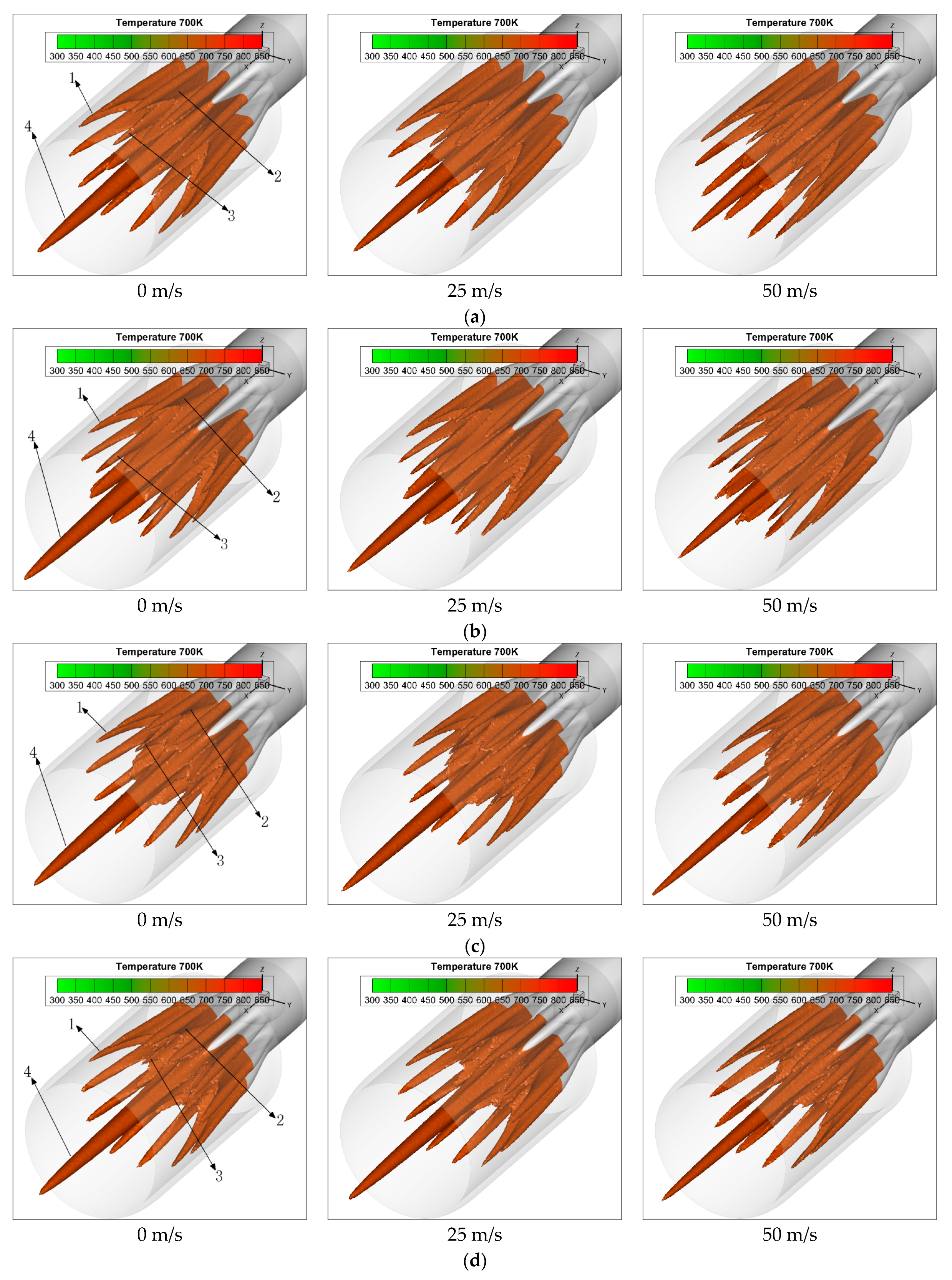
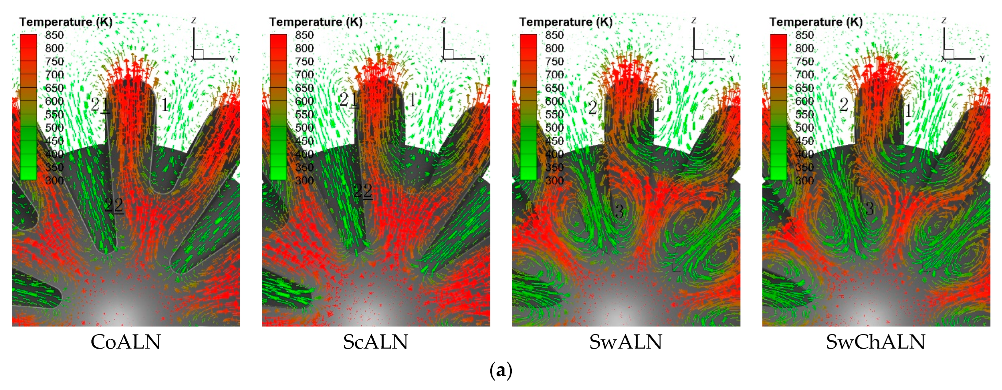
4.2. Jet Mixing Mechanisms

Figure 10 shows the distributions of velocity vectors at 0.50d for each alternating-lobe nozzle at three far-field velocities. The color of the velocity vectors represents the temperature of the local flow, and all scaling factors are kept the same. It can be seen in Figure 10 that the two opposite cross flows of the hot and cool streams convolve to form the longitudinal vortices.
As shown in Figure 10, the vortex cores of the CoALN longitudinal vortices formed off the sidewalls of the deep valleys (i.e., the longitudinal vortices shed from the sidewalls of the deep valleys) locate near the lobe crests at all three far-field velocities, and there are no visible vortex cores near the deep valleys. However, the cool stream moves forward and sideward through the deep valleys into the hot stream. The vortex cores of the longitudinal vortices off the sidewalls of the shallow valleys also locate near the lobe crests but are both radially and circumferentially smaller. In contrast, mixing in ScALN occurs earlier in the region off the sidewalls of the shallow valleys, but later in the region off the sidewalls of the deep valleys. Consequently, the penetration depth of the cool stream and circumferential scale of the longitudinal vortices off the sidewalls of the deep valleys are both smaller. In addition, the longitudinal vortices off the sidewalls of the shallow valleys have a greater circumferential scale and a slightly smaller radial scale. This results in the longitudinal vortices off the sidewalls of the deep valleys being slimmer, whereas those off the sidewalls of the shallow valleys being plumper. For CoALN and ScALN, the shape of the longitudinal vortices off the sidewalls of the deep valleys indicates that the volute, which circumvolves around the vortex core, can be regarded as a distinct “body” of the longitudinal vortices, whereas the remnant narrow is designated as the “tail”. Compared with CoALN, the radial and circumferential scales of the body of ScALN are smaller.
Unlike in ScALN, mixing in SwALN not only occurs earlier in the region off the sidewalls of the shallow valleys than in CoALN, but also in the region off the sidewalls of the deep valleys. Moreover, a pair of large and intensive longitudinal vortices is formed when the hot stream flows over each sword deep valley (the longitudinal vortices off the sword deep valleys), thereby causing the hot stream in the region between the deep and shallow valleys to turn toward both sides. This deflection of the hot stream causes the longitudinal vortices off the sidewalls of the shallow valleys to have a larger circumferential scale, with the radial scale being made smaller through an intensification of the radial flow of the hot stream in the region between the deep and shallow valleys caused by longitudinal vortices off the sword deep valleys. In addition, the circumferential and radial scales of the longitudinal vortices off the sidewalls of the deep valleys are approximately equal to those of the CoALN and ScALN bodies, respectively. Therefore, the longitudinal vortices off the sidewalls in SwALN are plumper. In SwChALN, chevron spoilers extending from the narrow valleys augment the penetration depth of the shallow valleys, and as a result, the longitudinal vortices off the sidewalls of the shallow valleys are even slimmer than those in ScALN; that is, the radial scale is increased and the circumferential scale decreased. The radial and circumferential scales are also slightly increased for the longitudinal vortices off the sidewalls of the deep valleys but decreased for the longitudinal vortices off the sword deep valleys.
As the far-field velocity increases, the penetration depth of the hot stream decreases in the region off the lobe crests for each alternating-lobe nozzle, and in the region off the shallow valleys for all but CoALN. In SwALN and SwChALN, the longitudinal vortices off the sidewalls of the shallow valleys become slimmer, causing the vortex core to move closer to the shallow valley, whereas those off the sidewalls of the deep valleys become plumper.
As far as the mixing mechanism of the longitudinal vortices is concerned, a previous investigation [29] has concluded that the large-scale mixing rate is related to the intensity of attainable heat and mass convection in the longitudinal vortices. It is propounded in [30] that the side of the longitudinal vortices where the hot and cool streams that encounter each other can be divided into three segments: windward, sideward, and leeward. In the windward segment, the cool stream flows strongly toward the hot stream, whereas the main flow in the leeward segment is a mixed stream flowing toward the cool stream (if this is not obstructed then the hot stream generally flows radially in the region off the lobe crests). In the sideward segment, the main flow is a mixed stream flowing from the windward segment toward the leeward segment. This indicates that the windward segment has the fastest mixing, whereas the leeward segment has the slowest mixing. The plumper longitudinal vortices enhance mixing because their windward segment is longer. Although this conclusion is based on only one far-field velocity of 0 m/s [30], it is nevertheless consistent with the results presented in Figure 7, Figure 8, and Figure 10.
As shown in Figure 7 and Figure 8, mixing in the region off the sidewalls of each alternating-lobe nozzle is faster near the shallow valleys than near the lobe crests for all three far-field velocities. The reason for this is that the windward segments of the bodies in CoALN and ScALN, the longitudinal vortices off the sidewalls of the deep valleys in SwALN and SwChALN, and the longitudinal vortices off the sidewalls of the shallow valleys in each alternating-lobe nozzle are located closer to the shallow valleys (Figure 10). The areas of the unmixed hot stream in the region between the deep and shallow valleys in each alternating-lobe nozzle also decrease to different extents, with the hot stream in the region between the deep and shallow valleys mixing surprisingly fast in SwALN and SwChALN. This can be explained by the fact that the windward segment is observed at the tail near the deep valley in CoALN and ScALN, whereas, in SwALN and SwChALN, the windward segment of the longitudinal vortices off the sword deep valleys is longer (Figure 10).
Mixing in the region off the sidewalls of the shallow valleys in ScALN is faster than in CoALN, and faster in SwALN than in SwChALN (Figure 8). From Figure 10, it can be concluded that this is caused by the plumper longitudinal vortices off the sidewalls of the shallow valleys having a longer windward segment. Compared with ScALN, the longitudinal vortices off the sidewalls of the shallow valleys in SwChALN are slightly slimmer, but those off the sidewalls of the deep valleys are plumper (Figure 10); thus, as shown in Figure 7, mixing in the region off the sidewalls is faster in SwChALN. As the far-field velocity increases, the longitudinal vortices off the sidewalls of the shallow valleys of SwALN and SwChALN are slimmed down, whereas those off the sidewalls of the deep valleys are plumped up (Figure 10). As a result, mixing is decelerated in the region off the sidewalls of the shallow valleys but accelerated in the region off the sidewalls of the deep valleys (Figure 8).
As the far-field velocity increases, the gradient of the axial velocity in the core region and region off the lobe crests of each alternating-lobe nozzle is decreased. In addition, it can be seen in Figure 10 that the penetration depth of the cool stream at the deep valleys is increased. Furthermore, at 1.5d in Figure 8, the cool stream around the core region is increased in CoALN and ScALN, but remains at a temperature approximately equal to TM in SwALN and SwChALN. Consequently, as shown in Figure 7, mixing is slowed in the region off the lobe crests for each alternating-lobe nozzle, but is faster in the core region of CoALN and ScALN. Moreover, the area of the hot stream decreases in SwALN and SwChALN, but the complete-mixing distance is slightly increased in the core region.
To analyze the movement of the total pressure recovery coefficient shown in Figure 9, it can be concluded from Figure 10 that the pressure loss is mostly induced by the cross flow of the hot and cool streams. As the far-field velocity increases, the cross flow of the hot stream is weakened, whereas that of the cool stream is intensified, but only to a small extent as the far-field velocity increases from 0 to 25 m/s (Figure 7, Figure 8 and Figure 10). Thus, for any given section within each of the alternating-lobe nozzles, the total pressure recovery coefficient calculated using Equation (4) is the highest with a far-field velocity of 25 m/s and lowest at 0 m/s.

5. Conclusions

In this study, jet mixings of a CoALN, ScALN, SwALN, and SwChALN were investigated at three far-field velocities. The results are summarized as follows:
(1) The stamping air intake can be introduced to increase the cool air involved in the mixing for an infrared suppressor of a helicopter. Meanwhile, the stamping air intake increases the amount of cool stream near the mixing tube, which can effectively decrease the temperature of the mixing tube, thus improving the infrared suppression performance.
(2) Under the two intake conditions, SwALN and SwChALN are recommended for a normal infrared suppressor with a short mixing tube because they can achieve a higher thermal mixing efficiency in a short distance and the total pressure loss is acceptable; however, CoALN and ScALN are more suitable for an integrated infrared suppressor with a longer mixing tube because they can achieve a similar thermal mixing efficiency with a lower total pressure loss when the mixing distance is longer.
(3) The four lobed nozzles form the longitudinal vortices with different shapes, and the far field velocity will affect the position and shape of the longitudinal vortices. The shape of the longitudinal vortices is closely related to the large-scale heat and mass convection. The plumper longitudinal vortices can bring faster mixing to the affected region.

Author Contributions

Conceptualization, Z.S.; methodology, Z.S.; software, Z.S.; validation, L.Z.; formal analysis, L.Z.; investigation, Y.D.; resources, Z.S.; data curation, Y.D.; writing—original draft preparation, Z.S.; writing—review and editing, Z.S.; visualization, Y.D.; supervision, B.Z.; project administration, Z.S. and B.Z.; funding acquisition, Z.S. and B.Z. All authors have read and agreed to the published version of the manuscript.

Funding

This research was funded by the National Natural Science Foundation of China, grant numbers 11862016 and 12262023.

Data Availability Statement

Not applicable.

Conflicts of Interest

The authors declare no conflict of interest.

Abbreviations

CoALNCoplanar alternating-lobe nozzle
ScALNScarfing alternating-lobe nozzle
SwALNSword alternating-lobe nozzle
SwChALNSword and chevron alternating-lobe nozzle
NLNNormal lobed nozzle
dEquivalent diameter of the exit of CoALN [mm]
DDiameter of the mixing tube [mm]
xAxial distance measured from the trailing edge of the CoALN [mm]
mhMass flux of the hot stream [kg/s]
mcMass flux of the cool stream [kg/s]
mmMass flux of the local mixing stream [kg/s]
ThTemperature of the hot stream [K]
TcTemperature of the cool stream [K]
TmTemperature of the local mixing stream [K]
TMTemperature after complete mixing of the hot and cool streams [K]
P h * Total pressure of the hot stream [Pa]
P c * Total pressure of the cool stream [Pa]
P m * Total pressure of the local mixing stream [Pa]
ΦMass flux ratio
ηtrThermal mixing efficiency
σTotal pressure recovery coefficient

References

  1. Khan, A.; Akram, S.; Kumar, R. Experimental study on enhancement of supersonic twin-jet mixing by vortex generators. Aerosp. Sci. Technol. 2020, 96, 105521. [Google Scholar] [CrossRef]
  2. Singh, L.; Singh, S.N.; Sinha, S.S. Effect of Reynolds number and slot guidance on passive infrared suppression device. Aerosp. Sci. Technol. 2020, 99, 105732. [Google Scholar] [CrossRef]
  3. Zhou, Z.Y.; Huang, J. Mixed design of radar/infrared stealth for advanced fighter intake and exhaust system. Aerosp. Sci. Technol. 2021, 110, 106490. [Google Scholar] [CrossRef]
  4. Chen, H.Y.; Cai, C.P.; Jiang, S.B.; Zhang, H. Numerical modeling on installed performance of turbofan engine with inlet ejector. Aerosp. Sci. Technol. 2021, 112, 106590. [Google Scholar] [CrossRef]
  5. Mirjalily, S.A.A. Lambda shock behaviors of elliptic supersonic jets; a numerical analysis with modification of RANS turbulence model. Aerosp. Sci. Technol. 2021, 112, 106613. [Google Scholar] [CrossRef]
  6. Zhou, Z.Y.; Huang, J.; Yi, M.X. Comprehensive optimization of aerodynamic noise and radar stealth for helicopter rotor based on Pareto solution. Aerosp. Sci. Technol. 2018, 82–83, 607–619. [Google Scholar] [CrossRef]
  7. Zhou, Z.Y.; Huang, J.; Wu, N.N. Acoustic and radar integrated stealth design for ducted tail rotor based on comprehensive optimization method. Aerosp. Sci. Technol. 2019, 92, 244–257. [Google Scholar] [CrossRef]
  8. Zhou, Z.Y.; Huang, J.; Wang, J.J. Radar/infrared integrated stealth optimization design of helicopter engine intake and exhaust system. Aerosp. Sci. Technol. 2019, 95, 105483. [Google Scholar] [CrossRef]
  9. Zhou, Z.Y.; Huang, J.; Wang, J.J. Compound helicopter multi-rotor dynamic radar cross section response analysis. Aerosp. Sci. Technol. 2020, 105, 106047. [Google Scholar] [CrossRef]
  10. Shan, Y.; Zhang, J.Z.; Pan, C.X. Numerical and experimental investigation of infrared radiation characteristics of a turbofan engine exhaust system with film cooling central body. Aerosp. Sci. Technol. 2013, 28, 281–288. [Google Scholar] [CrossRef]
  11. Cheng, W.; Wang, Z.X.; Zhou, L.; Sun, X.; Shi, J. Influences of shield ratio on the infrared signature of serpentine nozzle. Aerosp. Sci. Technol. 2017, 71, 299–311. [Google Scholar] [CrossRef]
  12. Cheng, W.; Wang, Z.X.; Zhou, L.; Shi, J.; Sun, X. Infrared signature of serpentine nozzle with engine swirl. Aerosp. Sci. Technol. 2019, 86, 794–804. [Google Scholar] [CrossRef]
  13. Williams, N.J.; Moeller, T.M.; Thompson, R.J. Numerical simulations of high frequency transverse pulsed jet injection into a supersonic crossflow. Aerosp. Sci. Technol. 2020, 103, 105908. [Google Scholar] [CrossRef]
  14. Santana, E.R.; Weigand, B. Effect of the reaction mechanism on the numerical prediction of the performance of a scramjet combustor at cruise flight 8 Mach number. Aerosp. Sci. Technol. 2021, 112, 106595. [Google Scholar] [CrossRef]
  15. Wright, A.; Lei, Z.J.; Mahallati, A.; Cunningham, M.; Militzer, J. Effects of scalloping on the mixing mechanisms of forced mixers with highly swirling core flow. J. Eng. Gas Turb. Power 2013, 135, 071202. [Google Scholar] [CrossRef]
  16. Lei, Z.J.; Zhang, Y.F.; Zhu, Z.H.; Zhu, J. Numerical research on the mixing mechanism of lobed mixer with inlet swirl in linear radial distribution. Proc. IMechE. A J. Power Energy 2015, 229, 280–297. [Google Scholar] [CrossRef]
  17. Shan, Y.; Zhang, J.Z. Numerical investigation of flow mixture enhancement and infrared radiation shield by lobed forced mixer. Appl. Therm. Eng. 2009, 29, 3687–3695. [Google Scholar] [CrossRef]
  18. Lei, Z.J.; Mahallati, A.; Cunningham, M.; Germain, P. Effects of core flow swirl on the flow characteristics of a scalloped forced mixer. J. Eng. Gas Turb. Power 2012, 134, 111201. [Google Scholar] [CrossRef]
  19. Du, L.W.; Liu, Y.H.; Li, T. Numerical predictions of scarfing on performance of S-shaped nozzle with asymmetric lobe. J. Propul. Power 2015, 31, 604–618. [Google Scholar] [CrossRef]
  20. Shan, Y.; Zhang, J.Z.; Huang, G.P. Experimental and numerical studies on lobed ejector exhaust system for micro turbojet engine. Eng. Appl. Comp. Fluid 2011, 5, 141–148. [Google Scholar] [CrossRef]
  21. Liu, Y.H. Experimental and numerical research on high pumping performance mechanism of lobed exhauster-ejector mixer. Int. Commun. Heat Mass Transfer. 2007, 34, 197–209. [Google Scholar] [CrossRef]
  22. Pan, C.X.; Zhang, J.Z.; Shan, Y. Effects of exhaust temperature on helicopter infrared signature. Appl. Therm. Eng. 2013, 51, 529–538. [Google Scholar]
  23. Pan, C.X.; Zhang, J.Z.; Ren, L.F.; Shan, Y. Effects of rotor downwash on exhaust plume flow and helicopter infrared signature. Appl. Therm. Eng. 2014, 65, 135–149. [Google Scholar] [CrossRef]
  24. Zhang, J.Z.; Pan, C.X.; Shan, Y. Progress in helicopter infrared signature suppression. Chin. J. Aeronaut. 2014, 27, 189–199. [Google Scholar] [CrossRef] [Green Version]
  25. Liu, Y.H. Experimental and numerical investigation of circularly lobed nozzle with/without central plug. Int. J. Heat Mass Transf. 2002, 45, 2577–2585. [Google Scholar] [CrossRef]
  26. Koutmos, P.; McGuirk, J.J. Velocity and turbulence characteristics of isothermal lobed mixer flows. J. Fluids Eng. 1995, 117, 633–638. [Google Scholar] [CrossRef]
  27. Presz, W.M., Jr.; Reynolds, G. Alternating Lobed Mixer/Ejector Concept Suppressor. U.S. Patent No. 5884472, 23 March 1999. [Google Scholar]
  28. Yang, Z.Y.; Zhang, J.Z.; Shan, Y. Research on the influence of integrated infrared suppressor exhaust angle on exhaust plume and helicopter infrared radiation. Aerosp. Sci. Technol. 2021, 118, 107013. [Google Scholar] [CrossRef]
  29. Sheng, Z.Q.; Chen, S.C.; Wu, Z.; Huang, P. High mixing effectiveness lobed nozzles and mixing mechanisms. Sci. China Technol. Sci. 2015, 58, 1218–1233. [Google Scholar] [CrossRef]
  30. Sheng, Z.Q.; Huang, P.L.; Zhao, T. Configurations of lobed nozzles for high mixing effectiveness. Int. J. Heat Mass Tran. 2015, 91, 671–683. [Google Scholar] [CrossRef]
  31. Sheng, Z.Q. Jet mixing of lobed nozzles with spoilers located at lobe peaks. Appl. Therm. Eng. 2017, 119, 165–175. [Google Scholar] [CrossRef]
  32. Sheng, Z.Q.; Wu, Z.; Ji, J.Z.; Huang, P.L. Chevron spoiler to improve the performance of lobed ejector/mixer. Int. Commun. Heat Mass Tran. 2016, 77, 174–182. [Google Scholar] [CrossRef]
  33. Sheng, Z.Q.; Zhang, L.; Dan, Y.; Wang, Y.Y. Configuration of the lobed nozzle in an ejector mixer for extreme mixing efficiency. Int. J. Heat Mass Tran. 2022, 183, 122102. [Google Scholar] [CrossRef]
  34. Sheng, Z.Q.; Liu, J.Y.; Yao, Y.; Xu, Y.H. Mechanisms of lobed jet mixing: About circularly alternating-lobe mixers. Aerosp. Sci. Technol. 2020, 98, 105660. [Google Scholar] [CrossRef]
  35. Sheng, Z.Q.; Yao, Y.; Xu, Y.H. Suggestions on investigations of lobed jet mixing. Aerosp. Sci. Technol. 2019, 86, 415–429. [Google Scholar] [CrossRef]
  36. Hu, H.; Saga, T.; Kobayashi, T. Dual-plane stereoscopic PIV measurements in a lobed jet mixing flow. In Proceedings of the 43rd AIAA Aerospace Sciences Meeting and Exhibit, Reno, Nevada, USA, 10–13 January 2005. AIAA Paper 2005-0443. [Google Scholar]
  37. Xie, Y.; Liu, Y.H. A modified thermal mixing efficiency and its application to lobed mixer nozzle for aero-engines. Heat Transf. Res. 2011, 42, 317–335. [Google Scholar] [CrossRef]
Figure 1. Geometry and dimensions of a coplanar alternating-lobe mixer.
Aerospace 09 00700 g001
Figure 2. Geometry and dimensions of each lobed nozzle. (a) ScALN; (b) SwALN [29,30,34]; (c) SwChALN; (d) NLN, SwALN, and SwChALN.
Aerospace 09 00700 g002aAerospace 09 00700 g002b
Figure 3. Numerical simulation model. (a) simulation domain of the CoALN; (b) mesh model of the ScALN.
Aerospace 09 00700 g003
Figure 4. Experimental and simulated velocity vector and axial velocity distribution at different section locations downstream of a six-lobe nozzle [31,32,35]. (a) DP-SPIV [36]; (b) SST kω; (c) realisable kε.
Aerospace 09 00700 g004aAerospace 09 00700 g004b
Figure 5. Experimental and simulated maximum decay of longitudinal vorticity for a six-lobe nozzle [31,32,35].
Aerospace 09 00700 g005
Figure 6. Thermal mixing efficiency along the axis of each alternating-lobe nozzle at three far-field velocities.
Aerospace 09 00700 g006
Figure 7. 700-K temperature iso-surfaces for each alternating-lobe nozzle at three far-field velocities. Here, in terms of the hot stream regions, 1 is the region off the lobe crests, 2 is the region off the sidewalls, 3 is the region between the deep and shallow valleys, and 4 is the core region. (a) CoALN; (b) ScALN; (c) SwALN; (d) SwChALN.
Aerospace 09 00700 g007
Figure 8. Temperature distributions at 1.5d for each alternating-lobe nozzle at three far-field velocities. (a) 0 m/s; (b) 25 m/s; (c) 50 m/s.
Aerospace 09 00700 g008
Figure 9. Total pressure recovery coefficient along the axis of each alternating-lobe nozzle at three far-field velocities.
Aerospace 09 00700 g009
Figure 10. Distributions of velocity vectors at 0.50d for each alternating-lobe nozzle at three far-field velocities. Here, in terms of the longitudinal vortices, 1 is the vortex off the sidewall of the shallow valley, 2 is the vortex off the sidewall of the deep valley, 21 is the body of the vortex off the sidewall of the deep valley, 22 is the tail of the vortex off the sidewall of the deep valley, and 3 is the vortex off the sword deep valley. (a) 0 m/s; (b) 25 m/s; (c) 50 m/s.
Aerospace 09 00700 g010aAerospace 09 00700 g010b
Table 1. Mass flux ratios for each alternating-lobe nozzle at three far-field velocities.
CoALN
-0
ScALN
-0
Sw
ALN
-0
SwCh
ALN
-0
Co
ALN
-25
Sc
ALN
-25
Sw
ALN
-25
SwCh
ALN
-25
Co
ALN
-50
Sc
ALN
-50
Sw
ALN
-50
SwCh
ALN
-50
Φ1.09091.10981.12771.15071.59611.60661.61891.65062.62252.63982.63872.6582
Publisher’s Note: MDPI stays neutral with regard to jurisdictional claims in published maps and institutional affiliations.

