
Simulation and Application of a New Multiphase Flow Ablation Test System for Thermal Protection Materials Based on Liquid Rocket Engine

 ,
,
Abstract
:1. Introduction
2. Design and Simulation Method of the System
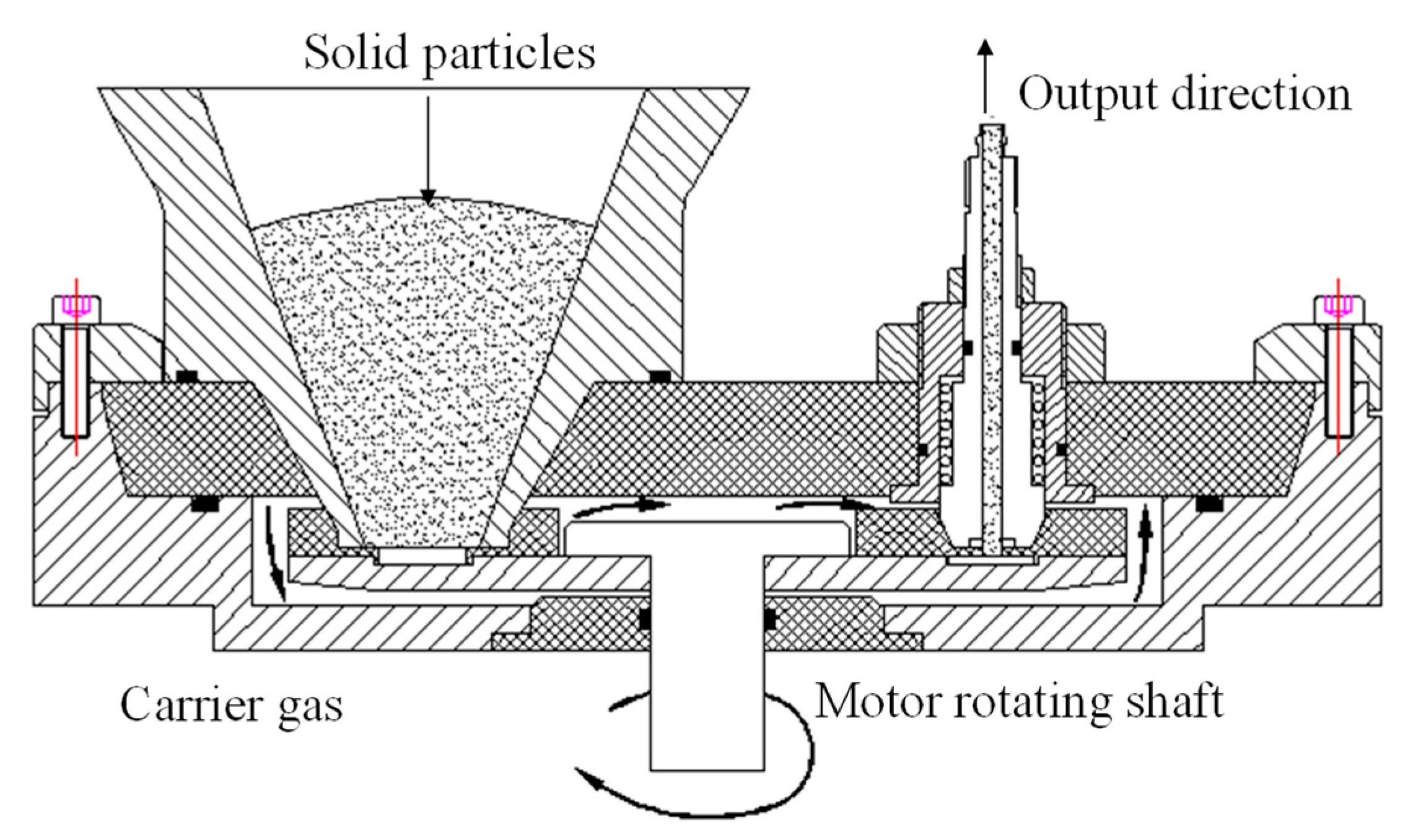
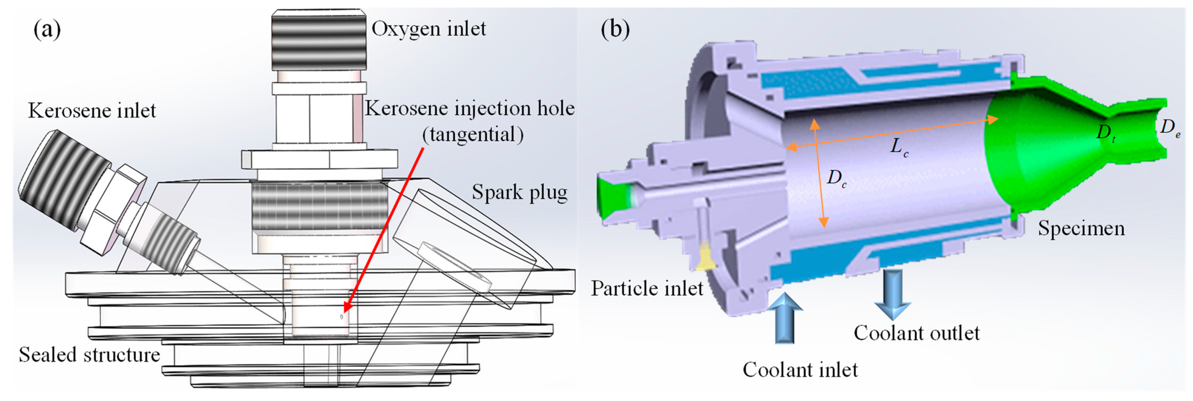
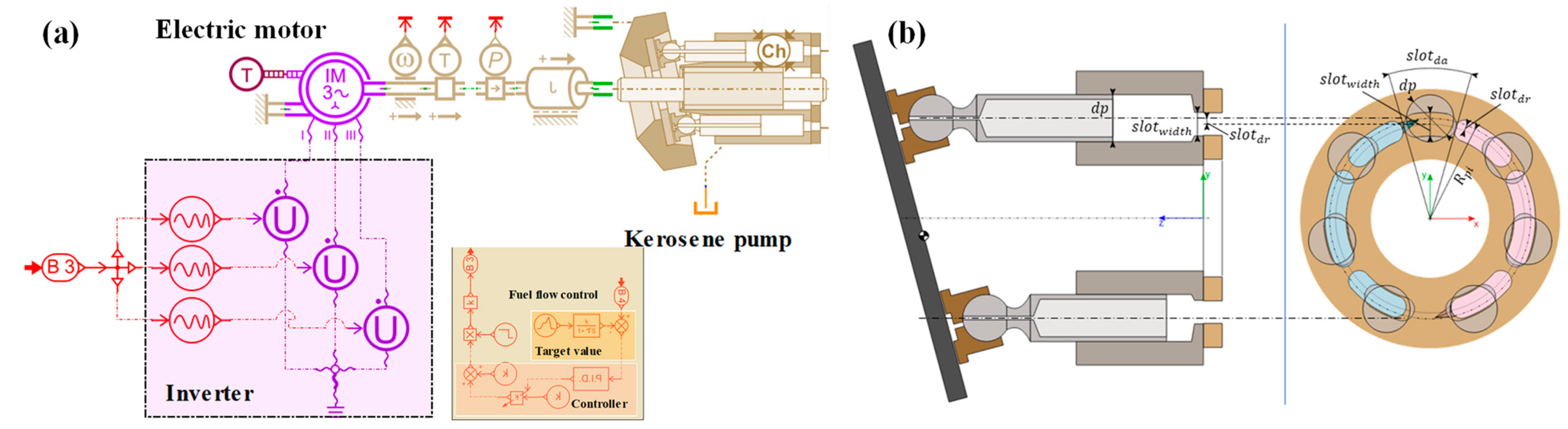
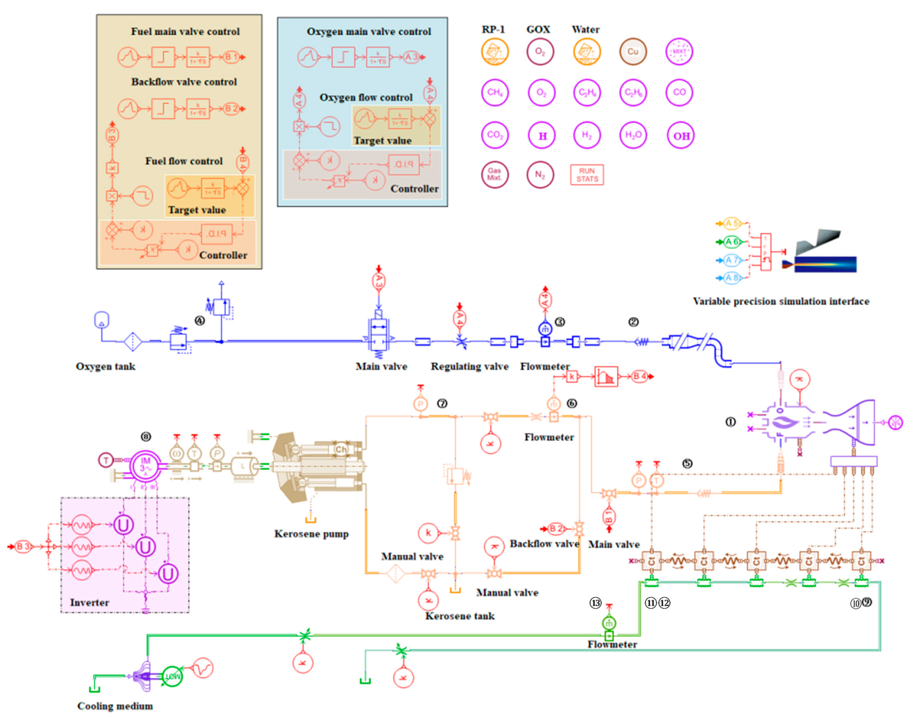
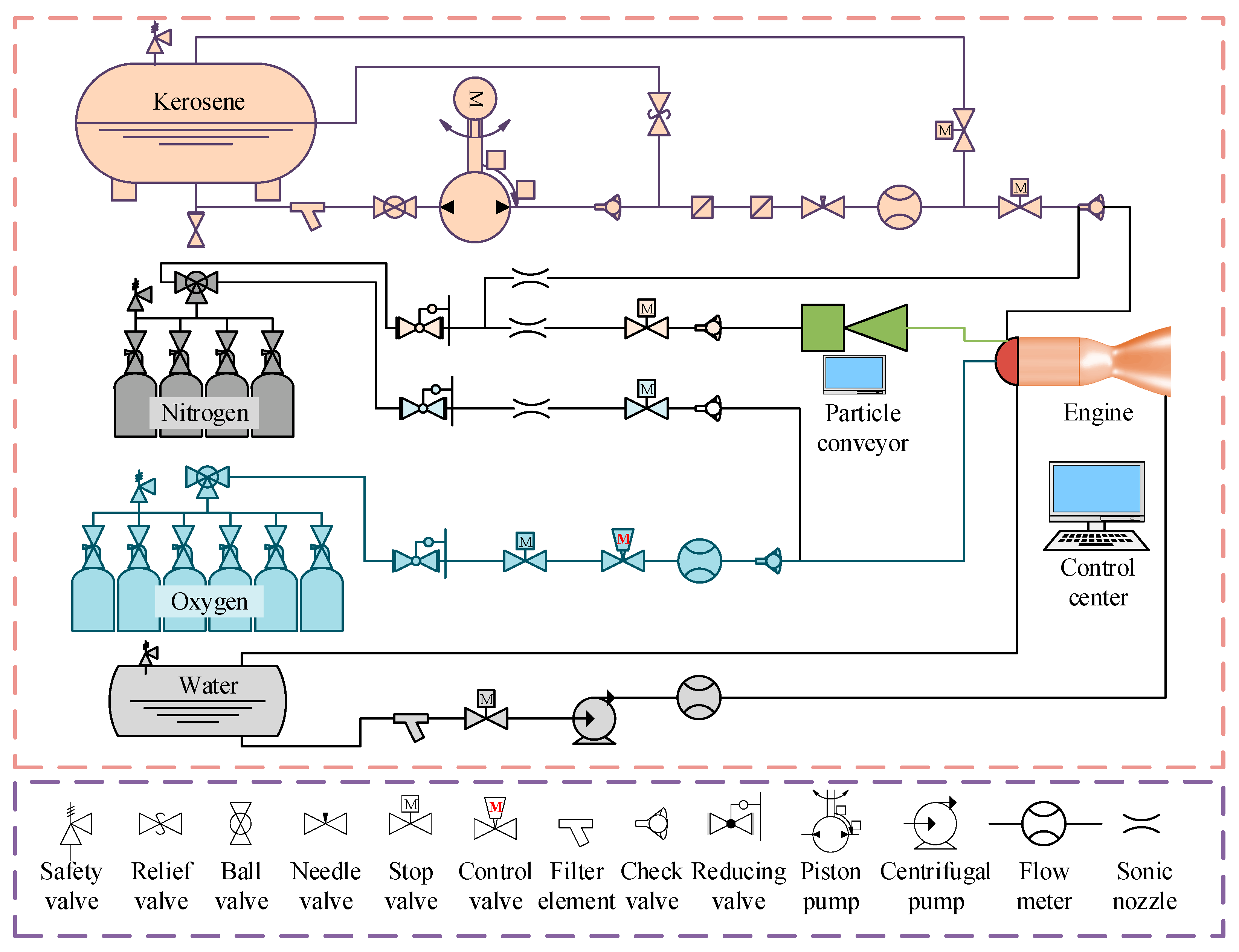
2.1. System Design and Composition
2.2. Working Process
2.3. System Simulation Model
2.3.1. Pipeline Numerical Model
2.3.2. Thermal Components Model
2.3.3. Pump Model
2.3.4. Valve Model
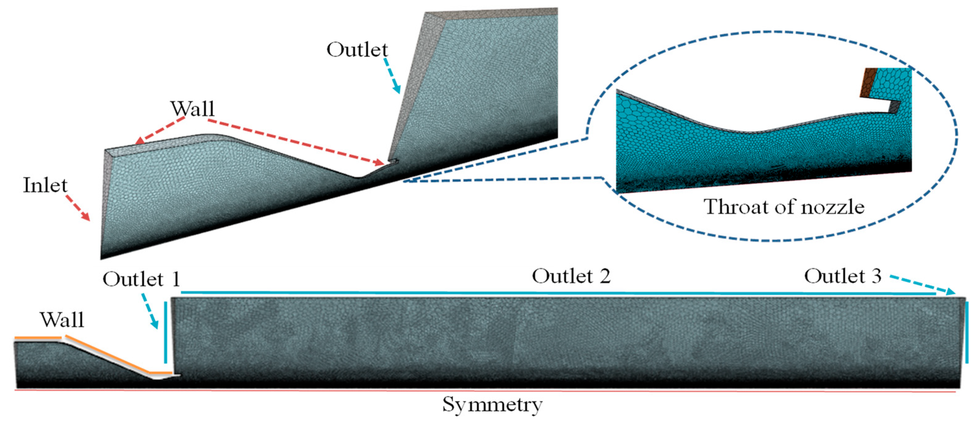
2.3.5. CFD Coupled Model of the Combustion Chamber
3. Experimental
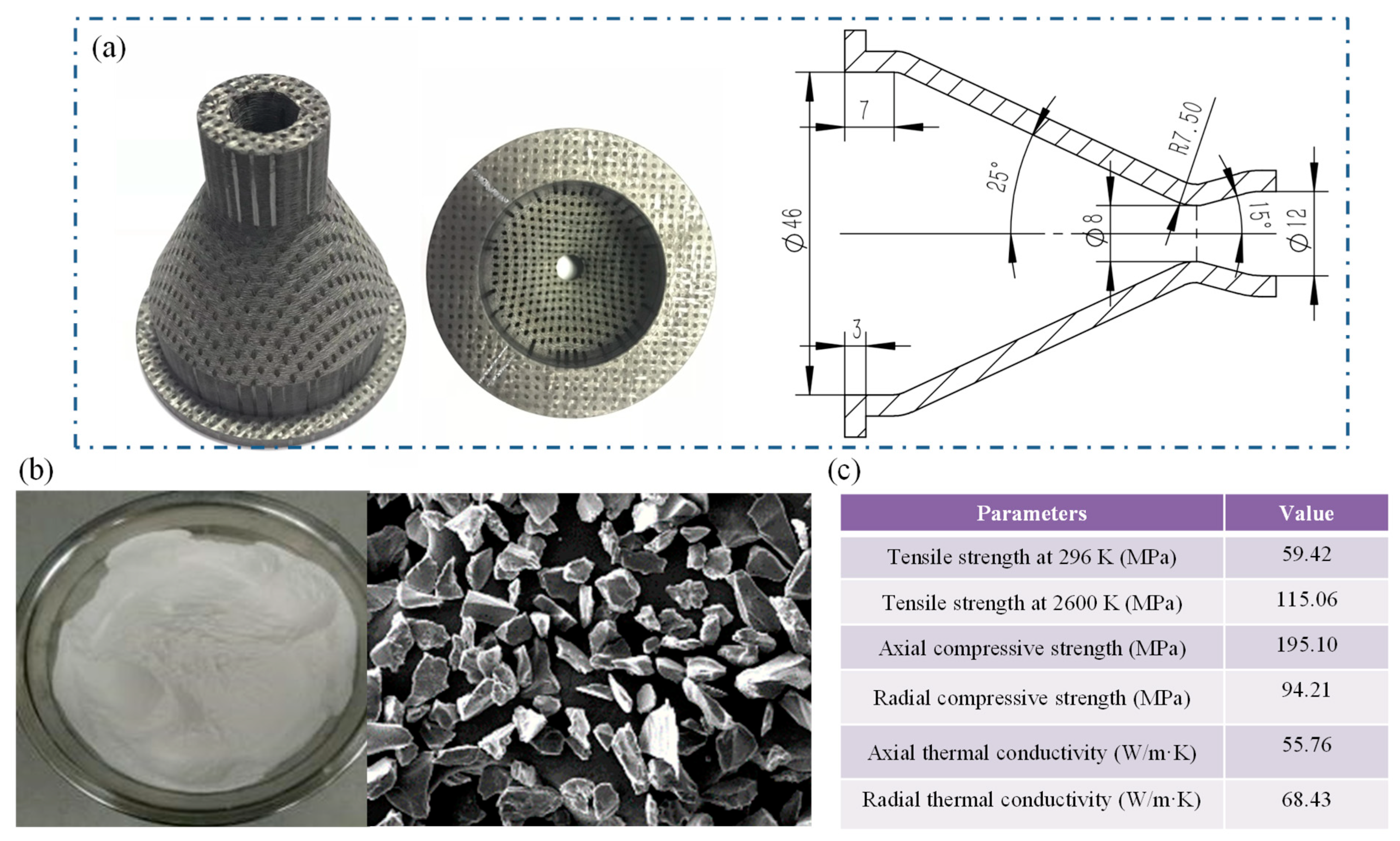
3.1. Material Preparation
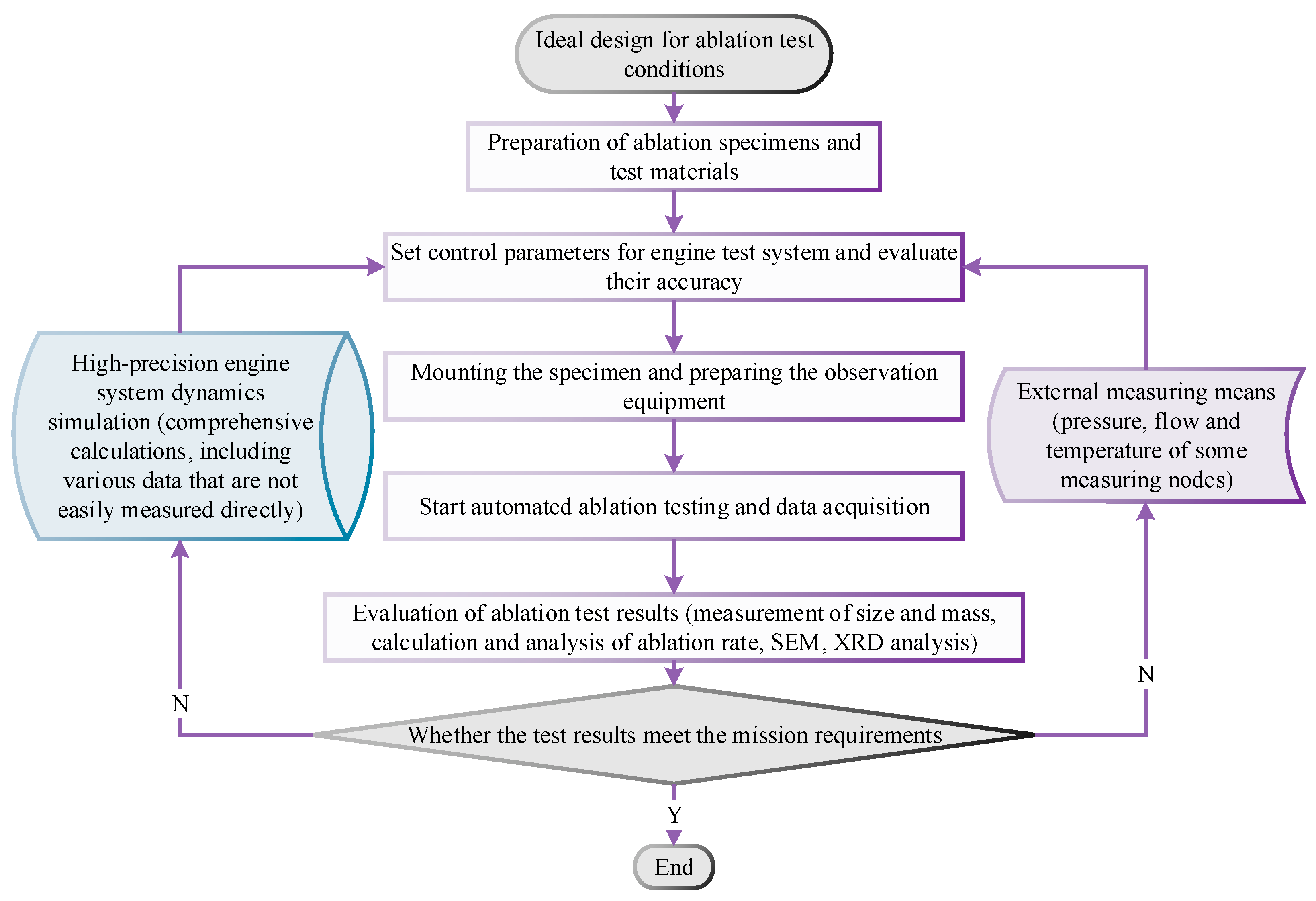
3.2. Ablation System Deployment and Test Procedure
3.3. Characterizations and Measurements
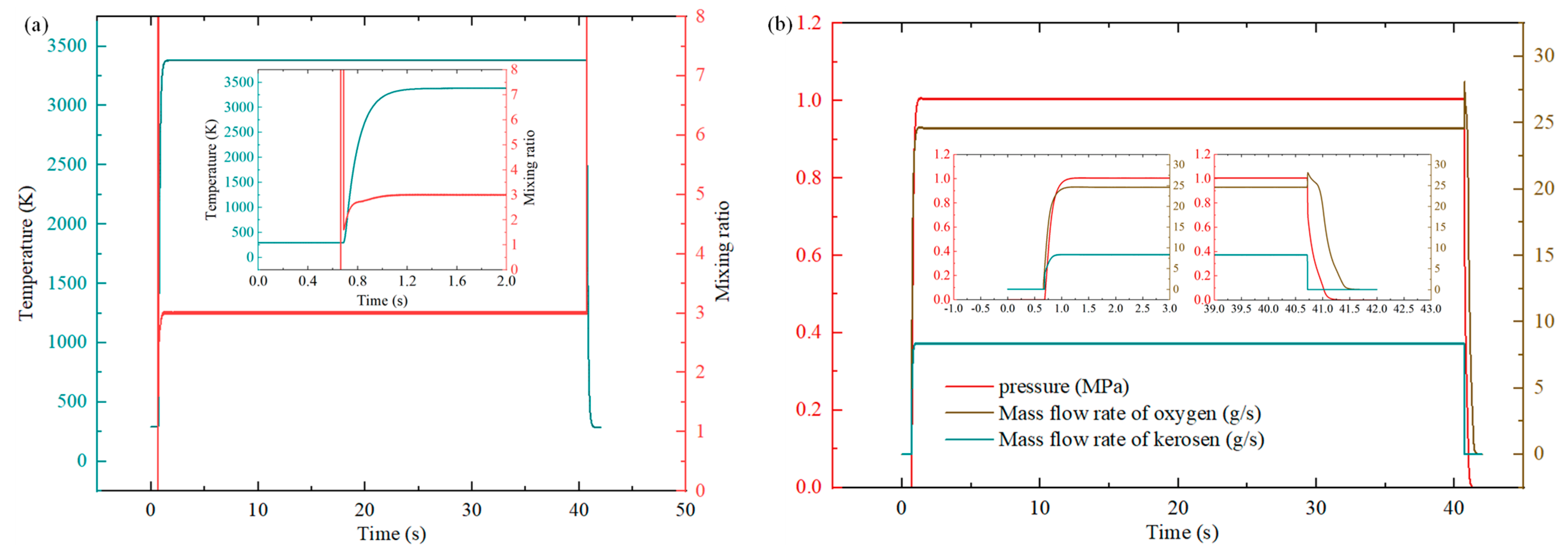
4. Results and Discussion
5. Conclusions
- (a)
- Based on the design of a gas-oxygen kerosene rocket engine, a multiphase flow ablation test system with adjustable particle concentration and propellant mixing ratio is developed by adding a high-pressure solid particle delivery device. Its unique internal flow field ablation operating temperature and pressure parameters range from 756 K to 3565 K and 0.2 to 4.2 MPa, respectively.
- (b)
- A multidisciplinary system simulation method of gas-oxygen kerosene rocket engine is proposed. Pipelines, valves, combustion chambers, pumps, and motors, are modeled through a modular graph modeling platform. Compared with the data of the sensors in the actual test, various simulation errors including pressure and temperature parameters are less than 5%, which can effectively guide the implementation of the test.
- (c)
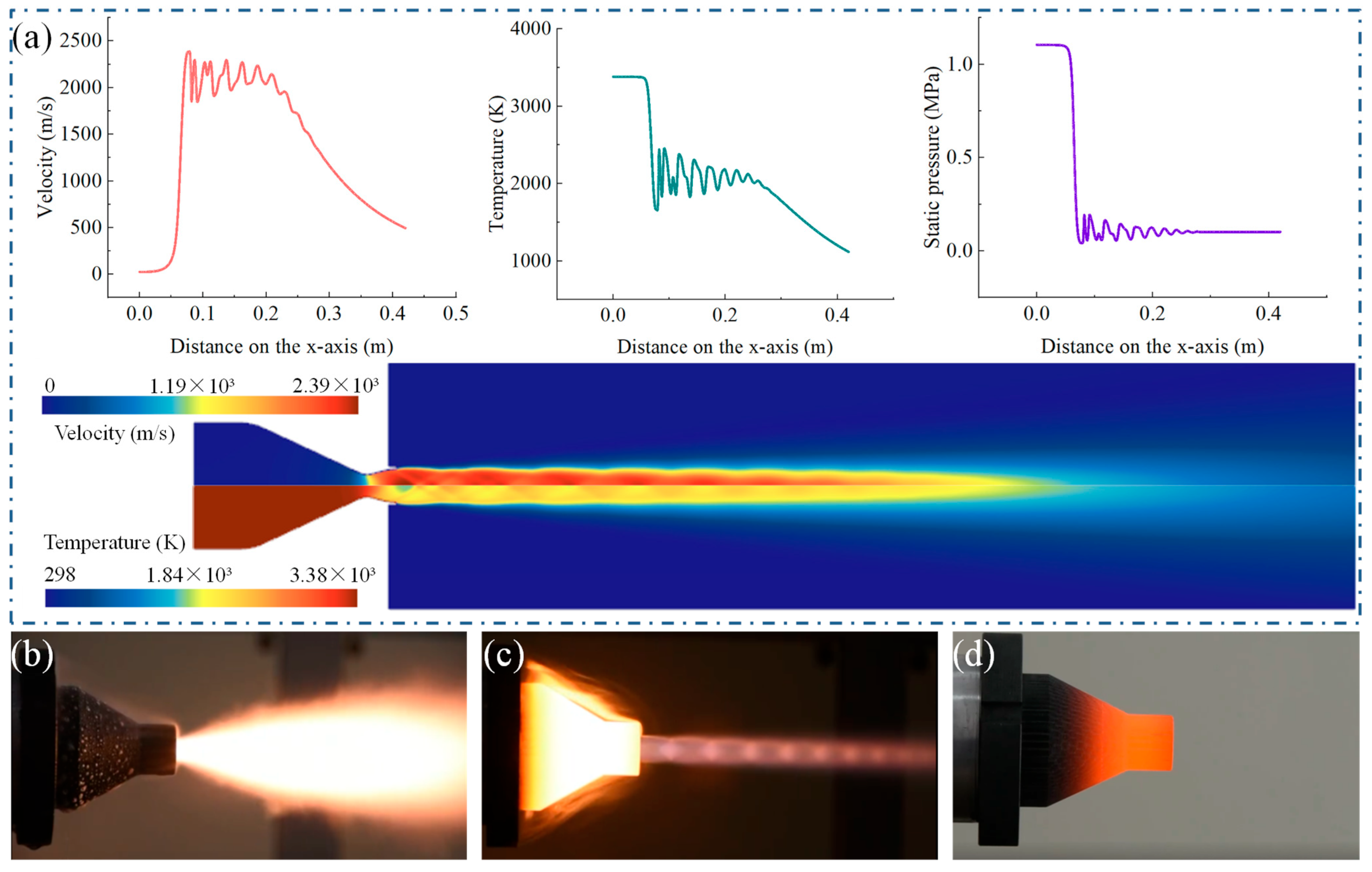
- The co-simulation of the 3D CFD simulation of the combustion chamber and the 0D ablation test system model is completed by a variable precision system simulation method. The data exchange is completed through TCP/IP in a fixed time step, and the spatial distribution results of temperature, pressure, and velocity of the combustion chamber concerned by the test personnel are automatically given in real time. The CFD simulation results are consistent with the jet structure of the actual ignition test.
- (d)
- The internal multiphase flow ablation test is carried out on the 4D C/C composite specimens. The kerosene flow rate of 8.2 g/s and the oxygen flow rate of 24.6 g/s make the combustion chamber temperature reach 3380 K and the pressure is about 1 MPa. The line ablation rate of the specimen is 0.053 mm/s, and the mass ablation rate is 0.073 g/s, which are similar to the ablation results of the actual flight test. The C/C composite shows relatively good ablation resistance, and the ablation is the result of the combined effect of thermochemical ablation and mechanical erosion of the multiphase flow.
Author Contributions
Funding
Data Availability Statement
Acknowledgments
Conflicts of Interest
References
- Borrelli, R.; Riccio, A.; Tescione, D.; Gardi, R.; Marino, G. Thermo-structural behaviour of an UHTC made nose cap of a reentry vehicle. Acta Astronaut. 2009, 65, 442–456. [Google Scholar] [CrossRef]
- Squire, T.H.; Marschall, J. Material property requirements for analysis and design of UHTC components in hypersonic applications. J. Eur. Ceram. Soc. 2010, 30, 2239–2251. [Google Scholar] [CrossRef]
- Hui, W.; Bao, F.; Wei, X.; Liu, Y. Ablation performance of a 4D-braided C/C composite in a parameter-variable channel of a Laval nozzle in a solid rocket motor. New Carbon Mater. 2017, 32, 365–373. [Google Scholar] [CrossRef]
- Liu, L.; He, G.Q.; Wang, Y.H.; Hu, S.-Q.; Liu, Y.-M. Factors affecting the primary combustion products of boron-based fuel-rich propellants. J. Propuls. Power 2017, 33, 333–337. [Google Scholar] [CrossRef]
- Windhorst, T.; Blount, G. Carbon-carbon composites: A summary of recent developments and applications. Mater. Des. 1997, 18, 11–15. [Google Scholar] [CrossRef]
- Jin, X.; Fan, X.; Lu, C.; Wang, T. Advances in oxidation and ablation resistance of high and ultra-high temperature ceramics modified or coated carbon/carbon composites. J. Eur. Ceram. Soc. 2018, 38, 1–28. [Google Scholar] [CrossRef]
- Wang, R.; Li, N.; Zhang, J.; Liu, B.; Yan, N.; Fu, Q. Ablation behavior of sharp leading-edge C/C-ZrC-SiC composites using 3000 °C oxyacetylene torch. Corros. Sci. 2022, 206, 110551. [Google Scholar] [CrossRef]
- Zhuang, L.; Fu, Q.-G.; Tan, B.-Y.; Guo, Y.-A.; Ren, Q.-W.; Li, H.-J.; Li, B.; Zhang, J.-P. Ablation behaviour of C/C and C/C–ZrC–SiC composites with cone-shaped holes under an oxyacetylene flame. Corros. Sci. 2016, 102, 84–92. [Google Scholar] [CrossRef]
- Helber, B.; Chazot, O.; Magin, T.; Hubin, A. Ablation of carbon preform in the VKI Plasmatron. In Proceedings of the 43rd AIAA Thermophysics Conference, New Orleans, LA, USA, 25–28 June 2012; p. 2876. [Google Scholar]
- Chen, Y.; Li, H.; Sun, L.; Ren, M. Plasma ablation properties of C/C-Cu composites. Acta Mater. Compos. Sin. 2014, 31, 1238–1243. [Google Scholar]
- Liu, Y.; Li, X.C.; Li, J.; He, G.-Q.; Li, Z.-Y. Ablation model based on porous charring layer under alumina erosion condition. AIAA J. 2019, 57, 4792–4803. [Google Scholar] [CrossRef]
- Gao, Y.; Zha, B.L.; Wang, J.J.; Sun, Z.-S.; Zhang, Z.-F.; Shi, Y.-A. Ablation mechanism of C/C–SiC and C/C–SiC–ZrC composites in hypersonic oxygen-enriched environment. Ceram. Int. 2022, 48, 22985–22993. [Google Scholar] [CrossRef]
- Wei, X.; Yang, Z.; Zhu, S.; Zhao, Z.; Ye, J.; Haidn, O.J. The Confirmation of Thermal Boundary Parameters in an Oxygen Kerosene Fuel-Rich Rocket Engine. Aerospace 2022, 9, 343. [Google Scholar] [CrossRef]
- Tong, Y.; Bai, S.; Zhang, H.; Ye, Y. Laser ablation behavior and mechanism of C/SiC composite. Ceram. Int. 2013, 39, 6813–6820. [Google Scholar] [CrossRef]
- Liu, L.; Yang, L.; Zhao, C.; Xiao, X.; Ye, Z.; Zhang, J.; Wang, G.; Wang, Y. Oxide-scale evolution and dynamic oxidation mechanism of ZrB2-SiC in high-enthalpy plasma wind tunnel. J. Eur. Ceram. Soc. 2021, 41, 3911–3921. [Google Scholar] [CrossRef]
- Yang, D.; Zhang, W.; Jiang, B.; Guo, Y. Silicone rubber ablative composites improved with zirconium carbide or zirconia. Compos. Part A Appl. Sci. Manuf. 2013, 44, 70–77. [Google Scholar] [CrossRef]
- Sutton, G.P. History of Liquid Propellant Rocket Engines; AIAA: Melbourne, FL, USA, 2006. [Google Scholar] [CrossRef]
- Zhang, Y.; Liu, K.; Cheng, M. Dynamics Theory and Application of Liquid Rocket Motor; Science Press: Beijing, China, 2005. [Google Scholar]
- Powell, M.; Butler, P.; Beck, L. Ground test simulation of rocket engine start transients. In Proceedings of the 11th Propulsion Conference, New Orleans, LA, USA, 19–21 March 1975; p. 1273. [Google Scholar]
- Meyer, C.; Maul, W. The application of neural networks to the SSME startup transient. In Proceedings of the 27th Joint Propulsion Conference, Sacramento, CA, USA, 24–26 June 1991; p. 2530. [Google Scholar]
- Goertz, C. A modular method for the analysis of liquid rocket engine cycles. In Proceedings of the 31st Joint Propulsion Conference and Exhibit, San Diego, CA, USA, 10–12 July 1995; p. 2966. [Google Scholar]
- Binder, M. An RL10A-3-3A rocket engine model using the Rocket Engine Transient Simulator (ROCETS) software. In Proceedings of the 29th Joint Propulsion Conference and Exhibit, Monterey, CA, USA, 28–30 June 1993; p. 2357. [Google Scholar]
- Leudiere, V.; Albano, G.; Ordonneau, G.; Masse, J.; Legrand, B. CARINS: A versatile and flexible tool for engine transient prediction development status. In Proceedings of the 24th Symposium (International) on Technologies for Space, Tokyo, Japan, 24–25 September 2004. [Google Scholar]
- Isselhorst, A. HM7B simulation with ESPSS tool on Ariane 5 ESC-A Upper Stage. In Proceedings of the 46th AIAA/ASME/SAE/ASEE Joint Propulsion Conference & Exhibit, Nashville, TN, USA, 25–28 July 2010; p. 7047. [Google Scholar]
- Fan, Z.; Huang, M.; Yu, Y. Modular Model of Space Propulsion System in the Whole Operation Process. J. Natl. Univ. Def. Technol. 2007, 29, 29–33. [Google Scholar]
- Zhang, L.; Li, W.; Duan, N. Modular general simulation of liquid rocket motor. J. Aerosp. Power 2011, 26, 687–691. [Google Scholar]
- Wang, C.; Zhang, X.; Gao, Y.; Chen, H. Research on the acceleration spin-up scheme of oxygen pre-pressure pump during the starting process of liquid oxygen kerosene supplemented combustion engine. Propuls. Technol. 2020, 41, 8. [Google Scholar] [CrossRef]
- Chen, H.; Liu, H.; Chen, J. Forced start process of supplementary combustion cycle engine. J. Aerosp. Power 2015, 30, 3010–3016. [Google Scholar] [CrossRef]
- Pan, H.; Zhang, L. Application of AMESim software in dynamic simulation of liquid rocket engine system. Rocket. Propuls. 2011, 37, 6–11. [Google Scholar] [CrossRef]
- Li, J. A fast method for dynamic simulation of low temperature engine system. Missile Space Launch Technol. 2012, 1, 13–17. [Google Scholar] [CrossRef]
- Zheng, D.; Wang, H.; Hu, J. Research on transient characteristics of high-thrust hydrogen-oxygen engine. Propuls. Technol. 2021, 42, 1761–1769. [Google Scholar] [CrossRef]
- Liu, Y.; Fu, B.; Yang, J.; He, G.; He, Y.; Liu, P. Modeling and simulation of electric pump-pressure liquid rocket engine system. Manned Aerosp. 2019, 25, 107–115. [Google Scholar] [CrossRef]
- Cui, P.; Song, J.; Li, Q.; Chen, L.; Liang, T.; Sun, J. Dynamics modeling and simulation analysis of electric pump-pressure liquid Kerosene Variable Thrust Rocket Engine: Part I-Single-Point Condition Analysis. Chin. J. Aeronaut. Astronaut. 2022, 43, 248–262. [Google Scholar] [CrossRef]
- Wang, Z. Design of Thrust Chamber for Liquid Rocket Motor; National Defense Industry Press: Beijing, China, 2014. [Google Scholar]
- Cao, T. Rocket Engine Dynamics; National University of Defense Technology Press: Beijing, China, 2004. [Google Scholar]
- Zhai, Y. Research on Dynamic Simulation of Expansion Cycle Engine Thrust Regulation Process; China Aerospace Science and Technology Corporation: Beijing, China, 2017. [Google Scholar]
- Glickman. Automatic Adjustment of Liquid Rocket Motor Translated by Gu Mingchu; Aerospace Press: Beijing, China, 1995. [Google Scholar]
- Siemens. Simcenter AMESim 2021.1 Thermal Hydraulic Component Design Library User’s Guide; Siemens Industry Software NV: Plano, TX, USA, 2021. [Google Scholar]
- Siemens. Simcenter AMESim 2021.1 Pneumatic Library User’s Guide; Siemens Industry Software NV: Plano, TX, USA, 2021. [Google Scholar]
- Siemens. Simcenter AMESim 2021.1 Signal, Control Library User’s Guide; Siemens Industry Software NV: Plano, TX, USA, 2021. [Google Scholar]
- Siemens. Simcenter AMESim 2021.1 Gas Mixture Library User’s Guide; Siemens Industry Software NV: Plano, TX, USA, 2021. [Google Scholar]
- Stark, R.H. Flow separation in rocket nozzles-an overview. In Proceedings of the 49th AIAA/ASME/SAE/ASEE Joint Propulsion Conference, San Jose, CA, USA, 14–17 July 2013; p. 3840. [Google Scholar]
- Siemens. Simcenter AMESim 2021.1 Thermal Library User’s Guide; Siemens Industry Software NV: Plano, TX, USA, 2021. [Google Scholar]
- Siemens. Simcenter AMESim 2021.1 Electrical Basics Library User’s Guide; Siemens Industry Software NV: Plano, TX, USA, 2021. [Google Scholar]
- Siemens. Simcenter AMESim 2021.1 Electric Motors and Drives library User’s Guide; Siemens Industry Software NV: Plano, TX, USA, 2021. [Google Scholar]
- Munson, B.R.; Okiishi, T.H.; Huebsch, W.W.; Rothmayer, A.P. Fluid Mechanics; Wiley: Singapore, 2013. [Google Scholar]
- Deng, W. Numerical Study of Particle Erosion in Solid Rocket Motor Nozzle; Harbin Engineering University: Harbin, China, 2017. [Google Scholar]
- Zhang, S.; Hu, C.; Xu, Y.; Chen, J. Combustion characteristic analysis on condensed-phase particle in SRM chamber. J. Solid Rocket. Technol. 2010, 33, 256–259. [Google Scholar] [CrossRef]
- Zhang, S.; Hu, C.; Xia, S.; Li, J. Experimental investigation on the condensed particles size distribution at srm nozzle throat. J. Propuls. Technol. 2012, 32, 245–248. [Google Scholar] [CrossRef]
- Wang, H.; Li, X. Multiscale approach to ablation modeling of in-plain C/C composite for nozzle throat. J. Solid Rocket. Technol. 2017, 3, 295–301. [Google Scholar]


| Parameters | Symbol | Unit | Value |
|---|---|---|---|
| Combustion chamber pressure | MPa | 1 | |
| Mixing ratio | 3.0 | ||
| Throat diameter | mm | 8 | |
| Total flow | g/s | 31.86 | |
| Oxygen flow | g/s | 23.895 | |
| Kerosene flow | g/s | 7.965 | |
| Nozzle exit diameter | mm | 12 | |
| Combustion chamber diameter | mm | 46 | |
| Combustion chamber length | mm | 120 | |
| Components | Mole Fraction |
|---|---|
| H2O | 0.28935 |
| CO | 0.26934 |
| CO2 | 0.15681 |
| OH | 0.09147 |
| H2 | 0.06050 |
| O2 | 0.06009 |
| H | 0.03971 |
| O | 0.03260 |
| Parameters | Flow Range (g/s) | Pressure at Source (MPa) | Precision | Temperature (K) | Chamber Pressure (MPa) |
|---|---|---|---|---|---|
| Kerosene | 2.00~29.47 | 6 | 1.5% | 756~3565 | 0.2~4.2 |
| Oxygen | 7.15~95.27 | 6 | 1% | ||
| Nitrogen | 0~41.67 | 6 | 1% | ||
| Coolant | 833.33 | 2 | 1.5% |
| Sample Number | Density (g/cm3) | Kerosen (g/s) | Oxygen (g/s) | Ratio | Particle (wt.%) | Ablation Time (s) |
|---|---|---|---|---|---|---|
| 1# | 1.91 | 8.2 | 24.6 | 3.0 | 10 | 40 |
| 2# | 1.89 | 8.2 | 24.6 | 3.0 | 10 | 40 |
| 3# | 1.92 | 8.2 | 24.6 | 3.0 | 10 | 40 |
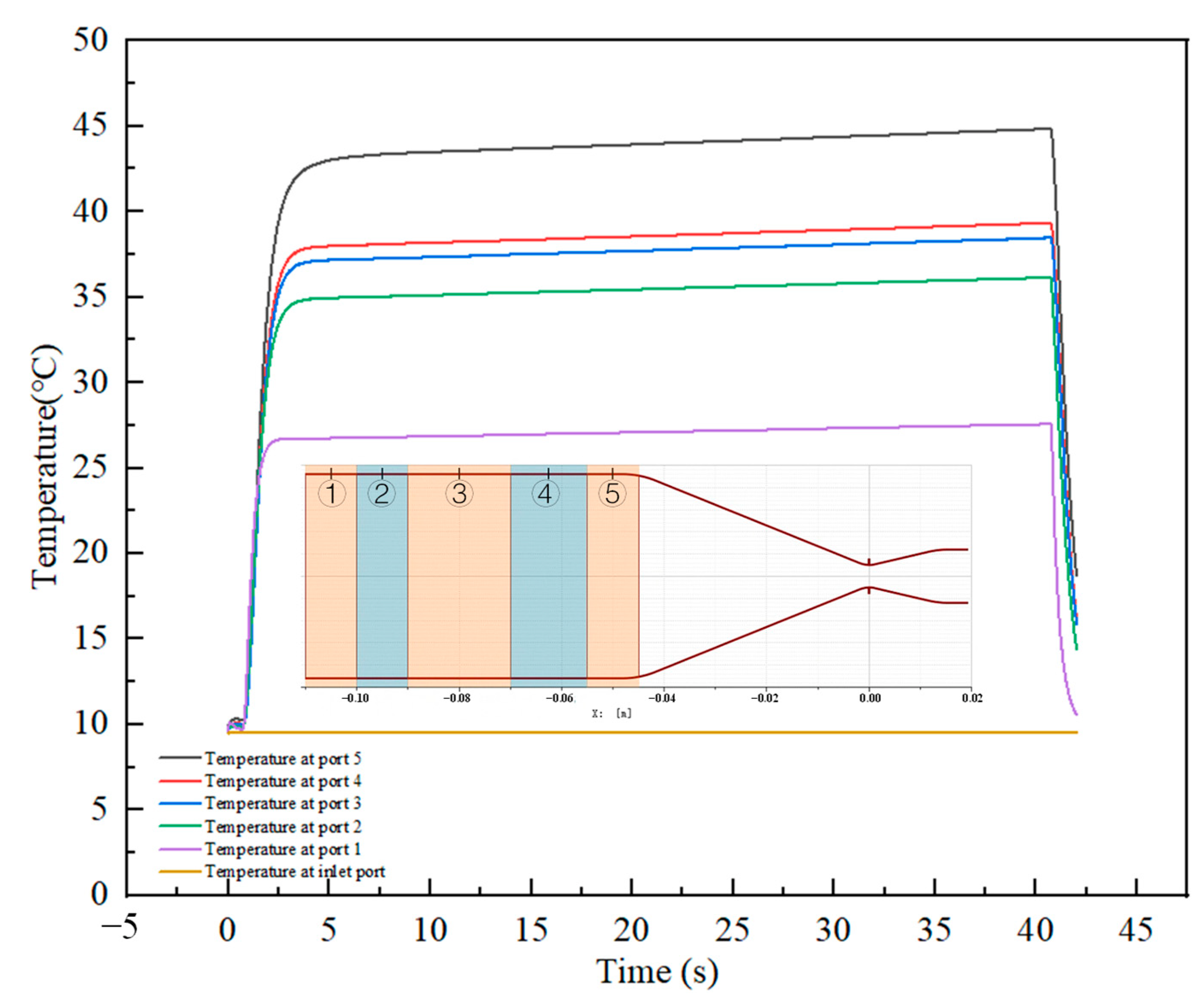
| NO. | Simulation Value | Sensor Value | NO. | Simulation Value | Sensor Value |
|---|---|---|---|---|---|
| 1# | 1.004 MPa | 1.01 MPa | 8# | 18.95 Hz | 19.75 Hz |
| 2# | 1.552 MPa | 1.58 MPa | 9# | 43.92 °C | 42.35 °C |
| 3# | 24.603 g/s | 24.6 g/s | 10# | 0.029 MPa | 0.04 MPa |
| 4# | 5.856 MPa | 5.64 MPa | 11# | 9.57 °C | 10.06 °C |
| 5# | 1.557 MPa | 1.61 MPa | 12# | 1.145 MPa | 1.21 MPa |
| 6# | 8.205 g/s | 8.2 g/s | 13# | 609.257 g/s | 620.4 g/s |
| 7# | 1.582 MPa | 1.63 MPa |
Publisher’s Note: MDPI stays neutral with regard to jurisdictional claims in published maps and institutional affiliations. |
© 2022 by the authors. Licensee MDPI, Basel, Switzerland. This article is an open access article distributed under the terms and conditions of the Creative Commons Attribution (CC BY) license (https://creativecommons.org/licenses/by/4.0/).
Share and Cite
Su, Q.; Zha, B.; Wang, J.; Yan, M.; Gao, Y.; Sun, Z.; Huang, W. Simulation and Application of a New Multiphase Flow Ablation Test System for Thermal Protection Materials Based on Liquid Rocket Engine. Aerospace 2022, 9, 701. https://doi.org/10.3390/aerospace9110701
Su Q, Zha B, Wang J, Yan M, Gao Y, Sun Z, Huang W. Simulation and Application of a New Multiphase Flow Ablation Test System for Thermal Protection Materials Based on Liquid Rocket Engine. Aerospace. 2022; 9(11):701. https://doi.org/10.3390/aerospace9110701
Chicago/Turabian StyleSu, Qingdong, Bailin Zha, Jinjin Wang, Mingxia Yan, Yong Gao, Zhensheng Sun, and Weifeng Huang. 2022. "Simulation and Application of a New Multiphase Flow Ablation Test System for Thermal Protection Materials Based on Liquid Rocket Engine" Aerospace 9, no. 11: 701. https://doi.org/10.3390/aerospace9110701
APA StyleSu, Q., Zha, B., Wang, J., Yan, M., Gao, Y., Sun, Z., & Huang, W. (2022). Simulation and Application of a New Multiphase Flow Ablation Test System for Thermal Protection Materials Based on Liquid Rocket Engine. Aerospace, 9(11), 701. https://doi.org/10.3390/aerospace9110701