Article

Mechanical Characteristics of Lunar Regolith Drilling and Coring and Its Crawling Phenomenon: Analysis and Validation

1
State Key Laboratory of Robotics and System, Harbin Institute of Technology, No. 92, Xidazhi St., Nangang Dist., Harbin 150001, China
2
School of Mechanical and Electrical Engineering, Nanjing University of Aeronautics and Astronautics, No. 29, Jiangjun St., Jiangning Dist., Nanjing 161005, China
3
College of Light Industry, Harbin University of Commerce, No. 138, Tongda St., Daoli Dist., Harbin 150006, China
*
Author to whom correspondence should be addressed.
Aerospace 2022, 9(11), 709; https://doi.org/10.3390/aerospace9110709
Submission received: 25 September 2022 / Revised: 5 November 2022 / Accepted: 10 November 2022 / Published: 12 November 2022

Abstract

:
The collection of lunar regolith with complete stratigraphic information is the key to analyzing the evolution and composition of the moon. To keep each sample’s stratification for further analysis, a sampling method called flexible-tube coring has been adopted for Chinses lunar explorations. Given the uncertain physical properties of lunar regolith, drilling force and core lift force should be adjusted immediately in piercing process. Otherwise, only a small amount of core could be sampled, and overload drilling faults could occur correspondingly. Due to the fact that the cored regolith is inevitably connected to the flexible tube, coring characteristics may have a great influence on both lifting force and sampling quantity. To comprehend the regolith coring characteristics, a flexible-tube coring motion mechanics model was established and verified to acquire the lifting force results accurately. Herein, the judgment conditions for the flexible tube crawling phenomenon are proposed. Finally, the accuracy of the model is verified by comparing it with the Chang’e V telemetry data. This article provides theoretical support for the design and regulation improvement of Chang’e VI drilling and coring in the future.

1. Introduction

Sample return is an important tool for recognizing the formation and evolution of extraterrestrial bodies and their resource endowment status. The Soviet Union, the United States, China and Japan have retrieved physical samples from the Moon and asteroids to deepen human knowledge of the Moon, asteroids, and the solar system through physical and chemical analysis of the returns [1,2,3]. Compared with lunar surface samples, profile samples with strati-graphic information have more important scientific value and can provide direct evidence for the formation and evolutionary history of lunar regolith. The lunar flexible-tube coring method is a highly feasible method for lunar regolith coring because of its good retention of lamina information and high coring rate.
The Soviet Luna-16 probe was the world’s first unmanned automatic sampling probe to complete the collection of lunar regolith samples and return to the ground [4,5], whose pendulum-type lunar regolith collection device was mounted on the pendulum-type robot arm on the side of the probe. Luna-16 only used the weight of the sampling device to provide drilling pressure during the drilling process, resulting in a low drilling pressure and shallow drilling depth [6,7]. The Luna-24 detector had a slide-type drilling and sampling device, and the flexible tube was turned inward into the inner cavity of the rigid-core tube synchronously by the winding mechanism during the drilling process to complete the final encapsulation of the lunar regolith samples. This design of sample collection mechanism improved the coring rate of deep lunar regolith and maintained the original stratigraphic information of lunar regolith samples to the maximum extent [8,9,10]. The United States completed six manned lunar missions. In six missions, astronauts used hollow thin-walled tubes to press in and take cores [11,12]. China’s Chang’e V probe has used a surface sampling manipulator and a drilling sampling device to obtain surface and profile samples of the moon, respectively. After being sealed, the sample is carried back to the earth by a returner, enriching the variety of lunar regolith samples owned by humans [13,14,15,16].
In order to provide theoretical and technical support for the development and optimization of the lunar regolith profile coring assembly, this paper presents a theoretical study of the mechanical properties of the flexible-tube coring assembly. Based on theoretical mechanics and material mechanics, a mechanical model of flexible-tube coring was established, and the correctness of the model was verified by using a drilling and mining test platform. The mechanical model not only describes the change trend of coring force during the coring process, but also has important engineering guidance significance for the development of flexible tube parameters. Based on the mechanical model, the crawling mechanism of the flexible tube during deep moon regolith coring is analyzed. Finally, the judgment conditions of the crawling phenomenon of the flexible tube are proposed.

2. Flexible-Tube Coring Principle

The principle of the flexible-tube coring method is shown in Figure 1. The flexible tube and core tube are initially installed inside the drill pipe with an outer helix and smooth inner wall. During the coring process, the flexible tube outside the core tube descends gradually with the core tube, turning inward from the bottom of tube to the inner cavity of tube and wrapping the soil core formed by drilling. At the end of drilling, a columnar soil core wrapped by the flexible tube is formed inside the core tube [17,18,19].
There is no direct contact between lunar regolith particles and the core tube, which makes the relative motion of lunar regolith particles weaker and avoids the friction between lunar regolith particles and the core tube. This eliminates the “force arch” between lunar regolith particles, effectively reducing the damage of deep lunar regolith stratigraphic information by the coring mechanism [20,21].

3. Modeling the Mechanics

3.1. External Wall Force Analysis

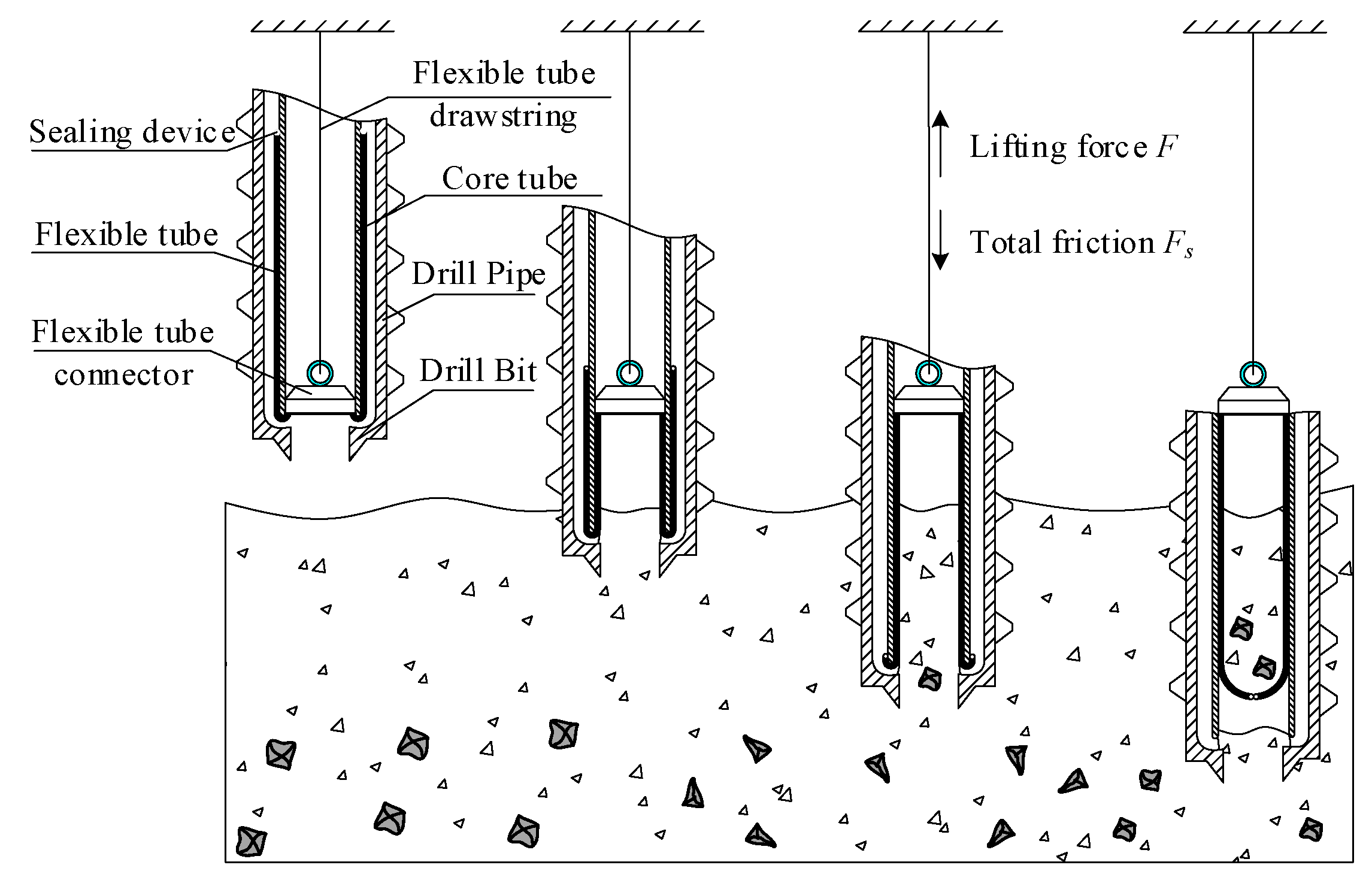
In the practical application, the flexible tube is stored on the outer wall of the core tube by means of pleated storage. The core taking process can be divided into two stages. In the first stage, the soft bag in the folded part is flattened continuously, and it mainly rubs against the outer wall of the core tube. In the second stage, the soft bag is completely flattened and gradually turned over to the inside of the core tube under the pull of rope force. The friction between the tube and outer wall consists of the sliding friction f sl and the static friction f st .
The coring of the flexible tube is shown in Figure 2. The parameters are shown in Table 1.
The flexible tube’s characteristic parameters can be expressed as follows: the total length of the flexible tube in its natural state is L, the length of the flexible tube in the folded state at the initial moment is l 1 , the length of the flexible tube in the flattened state is l 2 , the circumferential modulus of elasticity of the flexible tube is E c , the coefficient of sliding friction between the flexible tube and the core tube is μ m , and the coefficient of static friction between the flexible tube, and the core tube is μ s . The speed of drilling into the footprint is a constant value v 0 , and the speed of the flexible tube from the folded state to the flattened state is a constant value v 1 . The length of the flexible tube located on the inner wall of the core tube is L l 1 . The time required is t = L l 1 / v 0 . The speed of partial disappearance of the folds is v 1 = l 1 / t . The length of the flattened state at any given moment is l 2 = v 1 t .
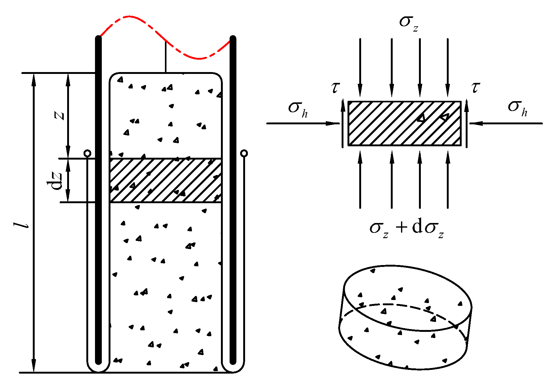
To explore the spreading state of the sliding friction f sl , the micro-element of the flexible tube needs to be force analysis. The longitudinal section of the micro-element is subject to circumferential tension T 1 as shown in Figure 3.
The perimeter and strain of the flexible tube recovered to the flattened state can be found as
ε 1 = Δ l 1 l = d 1 / 2 · d θ d 0 / 2 · d θ d 0 / 2 · d θ = d 1 d 0 d 0
Hooke’s law [22] shows that stress and strain are proportional when the material is subjected to stresses that do not exceed its proportional limits [23].
σ 1 = E c ε = E c d 1 d 0 d 0
T , = σ S and S = b b · d z , where b b is the thickness of the flexible tube and d z is the height of the micro-element.
T 1 = E c d 1 d 0 d 0 b b d z
The pressure of flexible tube on the core tube can be obtained as
d N 1 = 2 T 1 · sin d θ 2 = 2 E c d 1 d 0 d 0 b b d z · sin d θ 2
By integrating the above equation, the pressure on the outer wall of the core tube can be expressed as follows.
N 1 = 0 l 2 0 2 π 2 E c d 1 d 0 d 0 b b d z · sin d θ 2 = 2 π E c b b d 1 d 0 d 0 · l 1 v 0 t L l 1
Thus, the sliding friction in unfolded state can be calculated as follows.
f s l = μ m N 1 = 2 π μ m E c b b d 1 d 0 d 0 · l 1 v 0 t L l 1
In order to obtain the static friction in the pleated state, the equivalent diameter d 2 of the flexible tube in the fold should be determined first. Only the front part of the folded flexible tube has a movement trend, so the fold rate c b is introduced to represent the proportion of the part with a movement trend.
π 4 d 3 2 d 4 2 l 1 · c b = π 4 d 5 2 d 0 2 L
d 2 = d 3 + d 4 2 = d 4 + d 5 2 d 0 2 L / l 1 c b + d 4 2 2
The inner wall diameter of the core tube in the formula is d 5 = d 0 + 2 b b . The analysis of static friction between flexible tube and core tube in the folded state is similar to the analysis of the sliding friction, and the expression of f st can be obtained by the same reason.
f s t = μ s N 2 · c b = 2 π c b μ s E c b b a g d 2 d 0 d 0 l 1 l 1 v 0 t L l 1
Therefore, the friction between the flexible tube and the outer wall of the core tube is f 4 = f st + f sl .
f 4 = 2 π μ m E c b b d 1 d 0 d 0 · l 1 v 0 t L l 1 + 2 π c b μ s E c b b d 2 d 0 d 0 l 1 l 1 v 0 t L l 1 0 t < L l 1 v 0 2 π μ m E c b b L v 0 t d 1 d 0 d 0 L l 1 v 0 t L v 0

3.2. Inward Turning Force Analysis

The flexible tube’s turning process is divided into two parts: Flexible tube turning on the outside of the core tube and flexible tube turning on the inside of the core tube. In Figure 4, T o u t is the force between the outside flexible tube and the spreading state, and T i n is the force between the inside flexible tube and the inside of the core tube.
The force analysis of radial and circumferential elements is shown in Figure 5.
T is the tangential tension force on the micro-element, T r is the circumferential tension force on the micro-element, F f is the friction force on the micro-element, F r is the radial tightening force on the micro-element, d α is the radial angle of the taken micro-element, d θ is the circumferential angle of the taken micro-element, r is the radius of the corner of the core tube end, and the area of the taken micro-element is A = r d α b b . Building the force balance model yields
T + T + d T sin d α 2 + F r cos α + d α 2 = N F f + T cos d α 2 = T + d T cos d α 2 + F r sin α + d α 2 F r = 2 T r sin d θ 2 T r = E c A · d 0 / 2 + r + r cos α d 0 / 2 d 0 / 2 F f = μ m N
Since the radial and circumferential angles of the given flexible tube’s micro-element tend to zero, the above equation is simplified to obtain
d T d α = μ m T + 2 E c r 2 b b 1 + cos α d θ d 0 μ m cos α sin α
Given the force analysis of the flexible tube at the start and end of the inversion process, the above boundary condition can be obtained as
α = 0 T 0 = T o u t α = π 2 T π 2 = T m i d d l e
By solving analytically for T m i d d l e , we can obtain
T m i d d l e = T o u t + 2 C 1 2 C 1 μ m 2 + 1 2 C 1 μ m 2 + 4 e π 2 μ m + 2 μ m C 1 μ m 2 + 1 3 C 1 μ m 2 + 4
C 1 = 4 π E c r 2 b b d 0
Applying the same method as above, T i n can be calculated as
T i n = C 1 3 C 1 μ m 2 + 4 + e π 2 μ m · T
T = T o u t + 2 C 1 2 C 1 μ m 2 + 1 2 C 1 μ m 2 + 4 e π 2 μ m + 2 μ m C 1 μ m 2 + 1 3 C 1 μ m 2 + 4 3 C 1 μ m 2 + 4
In the formula, the friction force of the flexible tube during varus is f 3 = T i n T o u t .

3.3. Internal Cavity Force Analysis

The tube diameter of the flexible tube in the natural state is the same as that after coring. In this case, the flexible tube in the inner cavity is affected by the static friction force f 1 of the lunar regolith and the sliding friction force f 2 of the core tube.
Since the soil at different depths has various internal friction angles and densities, the lunar regolith located in the core-tube cavity is differentiated, as shown in Figure 6. The elements of lunar regolith are in static equilibrium. By integrating the friction force, the static friction force f 1 of lunar regolith on the flexible tube can be calculated.
f 1 = 0 l μ y σ h · π d 0 d z
where the height of the lunar regolith in the flexible tube is l = v 0 t , and μ y is the static friction coefficient between the lunar regolith and the flexible tube.
Flexible-tube-wrapped lunar regolith has a positive pressure on the flexible tube, σ h , resulting in a positive pressure between the flexible tube and the core tube, so the sliding friction between the two can be calculated using Coulomb’s law of friction.
f 2 = 0 l μ m σ h · π d 0 d z
The axial positive pressure σ z and lateral compressive stress σ h on the lunar micro-element inside the core tube can be converted by the lateral pressure coefficient in geomechanics.
σ h = K 0 σ z
where K 0 is the lunar regolith’s lateral pressure coefficient, the relationship of K can be obtained by fitting the empirical equation of Jaky [24,25,26], and the data on the friction angle and porosity ratio of the lunar regolith can be obtained from Lunar Prospector [27,28]. The relation between lunar regolith’s lateral pressure coefficient and drilling depth is shown in Figure 7.
K 0 = 1 2.2 z + 19.7 6.2 z 2 + 162.3 z + 1435
By drawing the chart according to the formula and taking K 0 = 0.358 , the characteristic height of the cored lunar regolith can be obtained.
λ = R 2 μ y K 0 = d 0 / 2 2 μ y K 0
As the lunar regolith wrapped by the flexible tube is not a semi-infinite body, the axial compressive stress σ z cannot be calculated by the method of vertical self-weight stress in geomechanics. If lunar regolith particles are regarded as grain particles, the axial compressive stress on lunar regolith particles can be calculated by the “granary effect” model.
σ z = p max 1 e z λ
where p max is the saturation compressive stress.
p max = ρ ( λ ) · g s λ = 1920 100 R + 24.4 μ y K 0 100 R + 36 μ y K 0 · g 6 · R 2 μ y K 0
The mechanical model of the coring process can be obtained by analyzing the forces on different parts of the flexible tube.
f 1 = 0 v 0 t A 1 ( 1 e B 1 z ) d z = A 1 B 1 ( 1 e B 1 v 0 t + B 1 v 0 t 1 ) t L v 0 f 2 = 0 v 0 t A 1 · μ m μ y ( 1 e B 1 z ) d z = A 1 B 1 · μ m μ y ( 1 e B 1 v 0 t + B 1 v 0 t 1 ) t L v 0 A 1 = 160 π d 0 g R 100 R + 24.4 μ y K 0 100 R + 36 μ y K 0 B 1 = ( 2 μ y K 0 ) ( 2 μ y K 0 ) R R

3.4. Flexible Tube Mechanics Model

Comprehensive analysis of the forces on different parts of the flexible tube requires the mathematical expression of the mechanical model of the flexible tube in the process of coring:
f = f 1 + f 2 + f 3 + f 4 = A 1 B 1 ( 1 e B 1 v 0 t + B 1 v 0 t 1 ) + A 1 B 1 · μ m μ y ( 1 e B 1 v 0 t + B 1 v 0 t 1 ) + ( 2 π μ m E c b b a g d 1 d 0 d 0 · l 1 v 0 t L l 1 + 2 π c b a g μ s E c b b a g d 2 d 0 d 0 ( l 1 l 1 v 0 t L l 1 ) + 2 C 1 2 C 1 μ m 2 + 1 2 C 1 μ m 2 + 4 ) e π 2 μ m + 2 μ m C 1 μ m 2 + 1 3 C 1 μ m 2 + 4 0 t < L l 1 v 0 3 C 1 μ m 2 + 4 e π 2 μ m + C 1 3 C 1 μ m 2 + 4 A 1 B 1 ( 1 e B v 0 t + B 1 v 0 t 1 ) + A 1 B 1 · μ m μ y ( 1 e B 1 v 0 t + B 1 v 0 t 1 ) + 2 π μ m E c b b a g L v 0 t d 1 d 0 d 0 + 2 C 1 2 C 1 μ m 2 + 1 2 C 1 μ m 2 + 4 e π 2 μ m L l 1 v 0 t L v 0 + 2 μ m C 1 μ m 2 + 1 3 C 1 μ m 2 + 4 3 C 1 μ m 2 + 4 e π 2 μ m + C 1 3 C 1 μ m 2 + 4
The value of each parameter of the mechanical model for flexible-tube coring is shown in Table 2.
Simulation results are shown in Figure 8. The ordinate F s represents the coring force. In the initial drilling process, the flexible tube gradually turns inside out, and the friction force of the inner wall of the core pipe acts on the flexible tube, making the core force increase in a quadratic function. When a certain drilling depth is reached, the internal stress of lunar regolith reaches a stable value, and the friction force between the flexible tube and outer wall of the core pipe occupies a dominant position. The coring force has a linear relationship with the length of the flexible tube. When the fold of the flexible tube disappeared, the compressive stress of the lunar regolith reached the maximum value, which made the friction on outer wall of the core tube reach the maximum value; therefore, the core force reached the maximum value. Subsequently, the length of the flexible tube on the outer wall of the core tube gradually shrank, and the coring force decreased.

4. Flexible Tube Crawl Analysis

As the flexible tube is made of fibrous material with a certain degree of elasticity, and there is friction between its surface and core tube wall, there may be a “crawling” phenomenon, also known as stick–slip behavior, when the speed is slow [28,29,30]. Therefore, theoretical analysis and physical modeling were conducted for the possible crawling problem.
Due to the thin wall thickness of the core tube, the friction force of the flexible tube at the rounded corner of the end of the core tube can be ignored. The friction force on the flexible tube during the movement can be divided into the friction force between the flexible tube and the outer wall of the core tube F 1 , and the friction force between the flexible tube and the inner wall of the core tube F 2 . When F 1 is transferred to the inner wall by the rounded corner, the friction force will increase linearly, so the overall friction force on the flexible tube is F f = s 1 F 1 + F 2 .
In order to simplify the system, it is assumed that the mass m i of the flexible tube does not change during crawling, and the vertical movement caused by surface roughness and surface corrugations of the core tube is ignored. The physical model of flexible tube crawling is shown in Figure 9.
The rope stiffness is k and the damping coefficient is c. The mathematical model of the crawling motion of the flexible tube can be established by the physical model.
m i x ¨ i + c ( x ˙ i v 0 ) + k ( x i v 0 t x 0 ) + s 1 F 1 + F 2 = 0
m i is the mass of the flexible tube in the flattened state, and it flips into internal state after the i 1 th crawling movement. x 0 is the rope stretch at the beginning of the ith crawling movement, and x i is the displacement of the flexible tube during the ith crawling movement.
From the flexible tube mechanics model, it can be seen that the speed of the folded-state flexible tube returning to the flattened state is l 1 v 0 l 1 v 0 ( L l 1 ) ( L l 1 ) . The length of the flexible tube in the flattened state at moment t is l 1 v 0 t l 1 v 0 t ( L l 1 ) ( L l 1 ) . The length of the flexible tube needed to complete the inward turning is v 0 t , and the mass ratio of the two is l 1 l 1 ( L l 1 ) ( L l 1 ) . Therefore, the mass of the flexible tube in the flattened state at any moment is m l 1 l 1 L L , and the mass of the flexible tube to complete the inward turning is m ( L l 1 ) m ( L l 1 ) L L . The length–mass coefficient of the flexible tube is s 2 = m m l l . The pressure coefficient between the outer wall flexible tube and the outer wall of the core tube is s 3 = N N l l . The pressure coefficient between the inner flexible tube and the inner wall of the core tube is s 4 = N N l l . Then, the friction force F 1 between the outer wall of the flexible tube and the outer wall of the core tube, and the friction force F 2 between the inner wall of the flexible tube and the inner wall of the core tube to give are
F 1 = m l 1 s 2 L s 3 · μ 1 = m l 1 s 2 L s 3 a 1 m l 1 s 2 L s 3 b 1 x ˙
F 2 = m L l 1 s 2 L s 4 · μ 2 = m L l 1 s 2 L s 4 a 2 m L l 1 s 2 L s 4 b 2 x ˙
Therefore, the friction force on the flexible tube is
F f = s 1 F 1 + F 2 = m l 1 s 3 a 1 + s 4 a 2 L l 1 s 2 L m l 1 s 3 b 1 + s 4 b 2 L l 1 s 2 L x ˙ = m A m B · x ˙
The mathematical model of the flexible tube’s crawling motion can be simplified as
m i x ¨ i + c m B x ˙ i + k x i = k v 0 t + c v 0 + k x 0 m i A
where x 0 is the ith crawl beginning when the amount of stretching of the pull rope, v 0 , is the constant, and the driving speed of the upper end of the pull rope, m i , is the instantaneous friction from when the flexible tube began to move. It can be seen that when the flexible tube is about to move, the force in its critical state is balanced, so c v 0 + k x 0 m i A = 0 .
m i x ¨ i + c m i B x ˙ i + k x i = k v 0 t
Let the input signal be R ( t ) = v 0 t . The following equation is obtained by the Rasch transform.
X ( s ) R ( s ) = k / m i m i s 2 + c m i B s + k / m i = ω n 2 s 2 + 2 ξ ω n s + ω n 2
where the undamped natural frequency is ω n = k / m i , the motion damping factor is ξ = c m i B / 2 k m i = c e q / k m i , and the equivalent damping of the system is c e q = c m i B / 2 .

5. Experiments

5.1. Preparation of Lunar Regolith Stimulant

In order to ensure the accuracy of the experiment, we prepared the lunar regolith simulant according to the characteristics of the samples collected from the Apollo16. The material composition of Apollo16 includes 70% anorthosite, 20% olivine and pyroxene, 15% glass, and other components. The particle diameters are mainly less than 1mm, and the relative density is in the range of 74–99%.
Finally, we determined to prepare the lunar regolith simulant with the ratio of anorthosite and basalt at 7:3, through three steps of particle size screening, grading, and drying [31,32,33]. The particle size gradation ratio of lunar regolith simulant is shown in Table 3. The obtained physical parameters are shown in Table 4.

5.2. Mechanical Model Experiment

In order to verify the correctness of the mechanical model, we used the drilling and sampling test platform developed in the laboratory to carry out the verification experiment. In this experiment, the core lifting force F of the soft bag being pulled upward was regarded as equal to the total friction force F s of the movement. The experimental stand is shown in Figure 10. The pieces and operation parameters are shown in Table 5. Each group of experiments was repeated five times to take the average. The relationship of force variation with time in the simulation and experiment is shown in Figure 11 and Figure 12.
At the beginning of the experiment, the pull rope was not pre-tightened, so it had a certain amount of elasticity, so the flexible tube began to invert after 20 s of the experimentation. The theoretical peak value is smaller than the experimental peak value, which is due to the high rounded-corner roughness of the core tube end. However, the error is within 8%, which is acceptable. In Figure 11, by comparing the relationship between the core lifting force in the experiment and the total friction force in the simulation, it can be concluded that the theory is basically consistent with the test.
The relationship between core lifting force and time in Figure 12 also demonstrates the above problems. Except for the common problem, the curve is basically consistent with the experimental curve. Therefore, it can be shown that the theoretical formula and mechanical model curve of flexible-tube coring are correct.

5.3. PBO Flexible Tube Crawl Verification

The crawling motion model is a second-order system, and the system will have a different performance level when the damping ratio ξ takes different values. To this end, the movement velocity and displacement of the flexible tube under different damping states were analyzed. Simulation parameters are shown in Table 6.
When ξ > 1 and c e q > k m i , the system is overdamped. The speed of flexible tube will tend to v 0 according to the exponential law, so no crawling phenomenon will occur. Results are shown in Figure 13a.
When 0 < ξ < 1 and 0 < c e q < k m i , the system is underdamped. The energy input by the rope is used entirely for damping and friction losses. Various disturbances appeared when the flexible tube crawled, and it tended to be isokinetic after attenuation. Results are shown in Figure 13b.
When ξ = 0 and c e q = 0 , the system is in the undamped free vibration state, the energy input by the upper end of the pull rope is completely consumed in the friction of the flexible tube, and the crawling phenomenon occurs.
In this experiment, the flexible tube was woven from PBO fiber. It has the characteristics of high specific strength, high temperature resistance, flame resistance, and so on. It can adapt to the temperature changes of 150–300 C that take place on the lunar surface, radiation, and the vacuum of space [34,35]. A flexible tube with PBO fiber as the base material is shown in Figure 14. The length–mass coefficient of the flexible tube is s 2 = m m l l = 3.51 × 10 3 kg / m ; the maximum mass of the flexible tube is m = s 2 l = 3.51 × 10 3 × 2.5 = 8.78 × 10 3 kg . The pull rope is a 1.5 mm in diameter steel wire rope; its stiffness and damping coefficient are k = 2.67 × 10 5 N / m , c = 1.6 × 10 5 N · s / m .
The pressure coefficient s 3 between the flexible tube and the outer wall of the core tube can be deduced from the formula
s 3 = 2 π E c b d 1 d 0 d 0 = 1056 N / m
The pressure N between the flexible tube and the inner wall of the core tube is
N = f 2 μ m = A 1 μ y B 1 ( 1 e B 1 v 0 t + B 1 v 0 t 1 )
Consider v 0 t increasing to 2.5 m. The simulation results are shown in Figure 15. It can be found that the pressure on the flexible tube and the depth of feed are approximately linearly related. A linear fit to the above curve is performed, and the fitting equation is
N = 4.772 v 0 t 0.998
The pressure coefficient s 4 between the flexible tube and the inner wall of the core tube can be approximated as s 4 = 4.772 N / m . Therefore, the damping ratio of the woven flexible tube with PBO as the substrate is
B = l 1 s 3 b 1 + s 4 b 2 L l 1 s 2 L = 1.21 × 10 7 s 1
ξ = c m i B 2 k m i = 1.6 × 10 5 8.78 × 10 3 × 1.21 × 10 7 2 2.67 × 10 5 × 8.78 × 10 3 = 555.19
According to the influence of damping ratio on crawling performance, it can be seen that when ξ > 1 , the system is in an overdamped state, and there is no crawling phenomenon between the flexible tube and core tube under the action of the pulling rope.

6. Discussion

On 2 December 2020, China’s Chang’e V probe completed drilling, lifting, and sample transfer on the moon’s surface in the Storm Ocean Luemke Mountain area. In the process of drilling the core at a depth of one meter, complicated operating conditions, such as drilling load fluctuation, drilling pressure exceeding the limit, and core lifting force exceeding the limit occurred between the coring drill tool and the lunar regolith. These problems were finally solved by self-controlled pre-programming and remote control on the ground. The main functional performance indexes of Chang’e vs. drilling and sampling device are shown in Table 7. Based on the characteristics of telemetry data, three representative drilling load conditions were identified: drilling load stable, Condition A; drilling load fluctuation, Condition B; and drilling pressure out of limit, Condition C.
Condition A: The drilling pressure and core lifting force showed a slow growth trend, and the drilling depth was 30–320 mm. It can be judged that the diameters of luner regolith particles at this depth were small and uniform; the drilling and core lifting device played an effective role. The comparison between the actual telemetry data and the simulation is shown in Figure 16. The telemetry data are basically consistent with the simulation curve.
Condition B: The drilling depth of section B was 460–582 mm. The fluctuation of B was caused by small-scale lunar regolith particles in front of the coring tool. The small-scale lunar regolith particles were gradually squeezed from the front of the cutting edge to the side, resulting in fluctuations in drilling force. The comparison between actual telemetry data and simulation is shown in Figure 17. The telemetry data are basically consistent with the simulation curve.
Condition C: Large critical particles entered the coring channel and formed two-force rod stagnation with the outer sheath, resulting in no sample injection to the flexible tube. The filled lunar regolith samples begin to slide, and the friction state of the cored flexible tube changed from high-filling-rate sliding friction to low-filling-rate sliding friction, which led to the extremely low load state of the cored force. By repeated rotary coring drill shake and dangling vibration after operation, the characteristics of particle vibration to the end of drilling hole, sealing the sample was completed. The drilling pressure and tension curves of Condition C are shown in Figure 18.
According to the telemetry data of Chang’e V coring sampling, the core lifting force increases slowly in stage A. It can be judged that the profile lunar regolith from this stage is fine-grained and non dense, and the core lifting force is basically consistent with the model simulation. In stage B, the core lifting force fluctuated due to the additional load of small-scale particles in the front section of the bit; the actual data follow the simulation curve. In stage C, large-scale critical particles blocked around 769 mm during drilling, resulting in a sudden drop in core lifting force and entering the sealing stage in advance. The final drilling depth of Chang’e V was about 1m, and the core lifting force of flexible tube increased slowly throughout the whole process. After three drilling stages, the flexible tube fold of coring still did not flatten and directly entered the core lifting and shaping stage, so the core lifting force did not enter the attenuation stage like the model predicted.

7. Conclusions

In this paper, the force magnitude of the flexible tube in deep lunar regolith coring process is divided into three parts, the detailed mechanical analysis is carried out, and the mechanical model of flexible tube cored is established. This mechanical model describes in detail the changing trend of flexible tube coring force, which lays a theoretical foundation for the formulation of pull rope and flexible tube parameters, the selection of flexible tube lifting motor and the analysis of lunar regolith coring rate. Aiming at the problem of flexible tube crawling, the concept of the differential unit was proposed, and the crawling mathematical model was established. The judgment conditions for the existence of flexible tube crawling phenomenon were obtained, which provide a judgment basis for testing whether the parameters such as the pulling rope’s radial and axial elastic modulus can eliminate the crawling phenomenon.
At last, the core telemetry data of Chang’e V were analyzed. It was found that the coring force trend of the flexible tube mechanical model is basically consistent with that of the telemetry coring force, which verified the correctness of the mechanical model. Finally, during the drilling process, the core was forced to stop due to extreme working conditions. The effect of soil particle size distribution with depth should be considered in subsequent studies to improve the core model and lay the foundation for future lunar sampling.

Author Contributions

Conceptualization, J.T.; Funding acquisition, W.Z.; Investigation, Z.Z.; Methodology, T.Y. and X.C.; Project administration, Y.T.; Resources, X.C.; Software, X.C.; Supervision, S.J. All authors have read and agreed to the published version of the manuscript.

Funding

This project is supported by Heilongjiang Postdoctoral Fund (number LBH-Z20145), China Postdoctoral Science Foundation (number 2021M690828), Self-Planned Task of State Key Laboratory of Robotics and System (number SKLRS202113B), National Natural Science Foundation of China (number 52105549), and Joint Funds of the National Natural Science Foundation of China (number U2013603).

Informed Consent Statement

Informed consent was obtained from all subjects involved in the study.

Data Availability Statement

The authors declare no conflict of interest. The funders had no role in the design of the study, in the collection, analysis, or interpretation of data, in the writing of the manuscript, or in the decision to publish the results.

Conflicts of Interest

The authors declare no conflict of interest.

References

  1. Gromov, V. Physical and mechanical properties of lunar and planetary soils. In Laboratory Astrophysics and Space Research; Springer: Dordrecht, The Netherlands, 1999; pp. 121–142. [Google Scholar]
  2. Pitcher, C.; Gao, Y. First implementation of burrowing motions in dual-reciprocating drilling using an integrated actuation mechanism. Adv. Space Res. 2017, 59, 1368–1380. [Google Scholar] [CrossRef] [Green Version]
  3. Chen, G.; You, H.; Huang, Z.; Fei, J.; Wang, Y.; Liu, C. An Efficient Sampling-Based Path Planning for the Lunar Rover with Autonomous Target Seeking. Aerospace 2022, 9, 148. [Google Scholar]
  4. Roedder, E.; Weiblen, P.W. Silicate melt inclusions and glasses in lunar soil fragments from the Luna 16 core sample. Earth Planet. Sci. Lett. 1972, 13, 272–285. [Google Scholar] [CrossRef]
  5. Simon, S.B.; Papike, J.; Laul, J. The lunar regolith-Comparative studies of the Apollo and Luna sites. Petrology of soils from Apollo 17, Luna 16, 20, and 24. In Proceedings of the Lunar and Planetary Science Conference Proceedings, Houston, TX, USA, 16–20 March 1981; Pergamon Press: New York, NY, USA; Oxford, UK, 1982; Volume 12, pp. 371–388. [Google Scholar]
  6. Pillinger, C.T.; Gowar, A. The separation and subdivision of two 0.5 g samples of lunar soil collected by the Luna 16 and 20 missions. Philos. Trans. R. Soc. Lond. Ser. A Math. Phys. Sci. 1977, 284, 137–143. [Google Scholar]
  7. Carrier, W.D., III; Mitchell, J.K.; Mahmood, A. The relative density of lunar soil. Proc. Lunar Sci. Conf. 1973, 4, 2403. [Google Scholar]
  8. Shkuratov, Y.; Kaydash, V.; Sysolyatina, X.; Razim, A.; Videen, G. Lunar surface traces of engine jets of Soviet sample return probes: The enigma of the Luna-23 and Luna-24 landing sites. Planet. Space Sci. 2013, 75, 28–36. [Google Scholar]
  9. Basilevsky, A.; Ivanov, B.; Ivanov, A.; Head, J. Clarification of sources of material returned by Luna 24 spacecraft based on analysis of new images of the landing site taken by lunar reconnaissance orbiter. Geochem. Int. 2013, 51, 456–472. [Google Scholar] [CrossRef]
  10. Ylikorpi, T. Preliminary Design of an Automated Lunar Soil Sampler. Master’s Thesis, Aalto University, Espoo, Finland, 1994. [Google Scholar]
  11. Nottingham, M.C.; Stuart, F.M.; Chen, B.; Zurakowska, M.; Gilmour, J.D.; Alexander, L.; Crawford, I.A.; Joy, K.H. Complex burial histories of Apollo 12 basaltic soil grains derived from cosmogenic noble gases: Implications for local regolith evolution and future in situ investigations. Meteorit. Planet. Sci. 2022, 57, 603–634. [Google Scholar]
  12. Allton, J.H. Catalog of Apollo Lunar Surface Geological Sampling Tools and Containers; NASA Lyndon B. Johnson Space Center: Houston, TX, USA, 1989. [Google Scholar]
  13. Zhang, H.; Li, C.; You, J.; Zhang, X.; Wang, Y.; Chen, L.; Fu, Q.; Zhang, B.; Wang, Y. The Investigation of Plume-Regolith Interaction and Dust Dispersal during Chang’E-5 Descent Stage. Aerospace 2022, 9, 358. [Google Scholar]
  14. Qian, Y.; Xiao, L.; Head, J.W.; van der Bogert, C.H.; Hiesinger, H.; Wilson, L. Young lunar mare basalts in the Chang’e-5 sample return region, northern Oceanus Procellarum. Earth Planet. Sci. Lett. 2021, 555, 116702. [Google Scholar]
  15. Qian, Y.; Xiao, L.; Wang, Q.; Head, J.W.; Yang, R.; Kang, Y.; van der Bogert, C.H.; Hiesinger, H.; Lai, X.; Wang, G.; et al. China’s Chang’e-5 landing site: Geology, stratigraphy, and provenance of materials. Earth Planet. Sci. Lett. 2021, 561, 116855. [Google Scholar] [CrossRef]
  16. Li, C.; Hu, H.; Yang, M.F.; Pei, Z.Y.; Zhou, Q.; Ren, X.; Liu, B.; Liu, D.; Zeng, X.; Zhang, G.; et al. Characteristics of the lunar samples returned by the Chang’E-5 mission. Natl. Sci. Rev. 2022, 9, nwab188. [Google Scholar]
  17. Zhao, G.; Liu, J.; Cui, J.; Wang, H.; Wen, G. Revealing the mechanism of the force dragging the soft bag in the dynamic process of deep soil coring. Powder Technol. 2019, 344, 251–259. [Google Scholar]
  18. Tang, J.; Quan, Q.; Jiang, S.; Liang, J.; Lu, X.; Yuan, F. Investigating the soil removal characteristics of flexible tube coring method for lunar exploration. Adv. Space Res. 2018, 61, 799–810. [Google Scholar]
  19. Quan, Q.; Li, S.; Jiang, S.; Hou, X.; Deng, Z. Control of drilling and coring device based on online identification. In Proceedings of the ASME International Mechanical Engineering Congress and Exposition, San Diego, CA, USA, 15–21 November 2013; Volume 56246, p. V04AT04A021. [Google Scholar]
  20. Shi, X.; Quan, Q.; Tang, D.W.; Jiang, S.; Hou, X.; Deng, Z. Experimental research on drilling and sampling of lunar soil simulant. Appl. Mech. Mater. 2012, 233, 218–223. [Google Scholar]
  21. Tang, J.; Quan, Q.; Jiang, S.; Li, H.; Bai, D.; Tang, D.; Deng, Z. Experimental investigation on flowing characteristics of flexible tube coring in lunar sampling missions. Powder Technol. 2018, 326, 16–24. [Google Scholar] [CrossRef]
  22. Rychlewski, J. On Hooke’s law. J. Appl. Math. Mech. 1984, 48, 303–314. [Google Scholar]
  23. Lei, S.; Young, R. Deformation of PBO/epoxy plain weave fabric laminae followed using Raman spectroscopy. Compos. Part A Appl. Sci. Manuf. 2001, 32, 499–509. [Google Scholar]
  24. Okochi, Y.; Tatsuoka, F. Some factors affecting K0-values of sand measured in triaxial cell. Soils Found. 1984, 24, 52–68. [Google Scholar]
  25. Zeng, X.; He, C.; Oravec, H.; Wilkinson, A.; Agui, J.; Asnani, V. Geotechnical properties of JSC-1A lunar soil simulant. J. Aerosp. Eng. 2010, 23, 111–116. [Google Scholar]
  26. Riad, B.; Zhang, X. Analysis of the Oedometer Test Results Using a New Method. In Proceedings of the Geo-Congress 2020: Modeling, Geomaterials, and Site Characterization, Minneapolis, MN, USA, 25–28 February 2020; American Society of Civil Engineers: Reston, VA, USA, 2020; pp. 321–331. [Google Scholar]
  27. Michalowski, R.L. Coefficient of earth pressure at rest. J. Geotech. Geoenviron. Eng. 2005, 131, 1429–1433. [Google Scholar]
  28. Yin, M.; Cheng, W.T.; Bai, L.J.; Guo, L.L. Numerical control machine tool motion simulation and analysis of parts of the crawling phenomenon. Adv. Mater. Res. 2014, 971, 592–595. [Google Scholar]
  29. Yu, C.; Liang, R.; Li, W.; Song, D. Analysis of creeping mechanism and eliminating measures of creeping phenomenon of machine feeding system. IOP Conf. Ser. Mater. Sci. Eng. 2019, 688, 033030. [Google Scholar]
  30. Tyvand, P.A. Free surface creeping motion related to a buckling phenomenon. Phys. Fluids 1984, 27, 2199–2201. [Google Scholar]
  31. Chen, C.; Quan, Q.; Deng, Z.; Jiang, S. Vibratory compaction method for preparing lunar regolith drilling simulant. Adv. Space Res. 2016, 58, 145–154. [Google Scholar]
  32. Tang, J.; Quan, Q.; Jiang, S.; Chen, C.; Yuan, F.; Deng, Z. A soil flowing characteristics monitoring method in planetary drilling and coring verification experiments. Adv. Space Res. 2017, 59, 1341–1352. [Google Scholar]
  33. Liang, J.; Ding, L.; Jiang, S.; Pang, Y.; Deng, Z.; Tang, J. Experimental study on an automatic drilling strategy for lunar regolith coring. In Proceedings of the 2017 IEEE International Conference on Robotics and Biomimetics (ROBIO), Macau, China, 5–8 December 2017; pp. 1389–1394. [Google Scholar]
  34. Kitagawa, T.; Murase, H.; Yabuki, K. Morphological study on poly-p-phenylenebenzobisoxazole (PBO) fiber. J. Polym. Sci. Part B Polym. Phys. 1998, 36, 39–48. [Google Scholar]
  35. Kumar, S.; Dang, T.D.; Arnold, F.E.; Bhattacharyya, A.R.; Min, B.G.; Zhang, X.; Vaia, R.A.; Park, C.; Adams, W.W.; Hauge, R.H.; et al. Synthesis, structure, and properties of PBO/SWNT Composites. Macromolecules 2002, 35, 9039–9043. [Google Scholar]
Figure 1. Location selection of the mineral material of the raw lunar regolith simulant and its back-scattered electron image after processing.
Aerospace 09 00709 g001
Figure 2. Structural diagram of the coring mechanism and friction schematic.
Aerospace 09 00709 g002
Figure 3. Schematic of circumferential tension of the outer-wall flexible tube’s micro-element in the unfolded state.
Aerospace 09 00709 g003
Figure 4. Illustration of the inner and outer forces when the core tube is turned inward.
Aerospace 09 00709 g004
Figure 5. Core tube outer flexible tube inversion force analysis.
Aerospace 09 00709 g005
Figure 6. Force analysis of cylindrical lunar regolith micro-element.
Aerospace 09 00709 g006
Figure 7. The relation between lunar regolith’s lateral pressure coefficient and drilling depth.
Aerospace 09 00709 g007
Figure 8. Mechanical model.
Aerospace 09 00709 g008
Figure 9. Physical model of the crawling motion of flexible tubes.
Aerospace 09 00709 g009
Figure 10. Flexible-tube coring mechanical model validation experiment.
Aerospace 09 00709 g010
Figure 11. Experiment 1: The relationship between the lifting force of the soft bag core and time.
Aerospace 09 00709 g011
Figure 12. Experiment 2: The relationship between the lifting force of the soft bag core and time.
Aerospace 09 00709 g012
Figure 13. Displacement and velocity simulation of flexible tube motion.
Aerospace 09 00709 g013
Figure 14. Flexible tube with radial shrinkage capability.
Aerospace 09 00709 g014
Figure 15. Pressure variation curve between inner flexible tube and lunar regolith and core tube with depth of feed.
Aerospace 09 00709 g015
Figure 16. Drilling load stable, Condition A.
Aerospace 09 00709 g016
Figure 17. Drilling load fluctuation, Condition B.
Aerospace 09 00709 g017
Figure 18. Drilling pressure out of limit Condition C.
Aerospace 09 00709 g018
Table 1. Diameter Parameters.
ParameterMeaning
d 0 Diameter of the internal flexible tube
d 1 Diameter of the flattened flexible tube
d 2 Diameter of the pleated flexible tube
d 3 Maximum diameter of flexible tube
d 4 Diameter of core tube outer wall
d 5 Diameter of core tube inner wall
Table 2. Characteristic parameters of the model.
Parameter μ m μ s μ y E c MPa r mm b b mm
Value0.10.20.052.30.750.15
Parameter d 0 mm d 1 mm d 2 mm l 1 m L m v 0 mm mm min min
Value1518200.6250
Table 3. Particle size gradation ratio.
Particle Size Gradation (mm)AnorthositeBasalt
0.025–0.07532.76%14.05%
0.075–0.518.05%7.72%
0.5–19.00%3.86%
1–5.67.58%3.25%
5.6–26.62.61%1.12%
Table 4. Characteristic parameters of the model.
Physical QuantitieValueUnit
Density1.4–2.3 g / c m 3
Cohesion34.4–41.9kPa
Friction Angle44.1–48.3
Deformation index0.97–1.32-
Shear modulus1.09–1.66cm
Compactness65–99%-
Uniaxial compressive strength4–55MPa
Tensile strength0.5–4MPa
Table 5. Characteristic parameters of the model.
Parameter μ m μ s μ y E c MPa r mm b b mm
Experiment 10.10.20.052.30.750.15
Experiment 20.10.20.052.30.750.15
Parameter d 0 mm d 1 mm d 2 mm l 1 m L m v 0 mm mm min min
Experiment 11620220.30.550
Experiment 21620220.350.650
Table 6. Parameters of flexible-tube-crawling simulation model.
Model ParameterData aData b
m i kg 11
c e q kg / s 0.10.001
k N / m 0.0010.001
v 0 m / s 0.00010.0001
Table 7. Core function and performance indexes of drilling sampling device.
Parameter MeaningNumerical Value
Maximum travel of drilling tool (mm)2376
Outer diameter of drill pipe (mm)32.7
Total length of drilling tool (mm)2356
Flexible tube materialKEVLAR-49/9000
Flexible tube size (mm)Diameter:15/Length:2500
Length of core lifting rope (mm)5220
Slewing driving speed (R/min)40/120
Feed drive speed (mm/min)50/100/130/160
Publisher’s Note: MDPI stays neutral with regard to jurisdictional claims in published maps and institutional affiliations.

