Article

An Integrated UWB-IMU-Vision Framework for Autonomous Approaching and Landing of UAVs

1
School of Aeronautic Science and Engineering, Beihang University, Beijing 100191, China
2
AVIC Xi’an Flight Automatic Control Research Institute, Xi’an 710076, China
3
Institute of Unmanned System, Beihang University, Beijing 100191, China
*
Authors to whom correspondence should be addressed.
Aerospace 2022, 9(12), 797; https://doi.org/10.3390/aerospace9120797
Submission received: 31 August 2022 / Revised: 6 November 2022 / Accepted: 30 November 2022 / Published: 5 December 2022

Abstract

:
Unmanned Aerial Vehicles (UAVs) autonomous approaching and landing on mobile platforms always play an important role in various application scenarios. Such a complicated autonomous task requires an integrated multi-sensor system to guarantee environmental adaptability in contrast to using each sensor individually. Multi-sensor fusion perception demonstrates great feasibility to compensate for adverse visual events, undesired vibrations of inertia sensors, and satellite positioning loss. In this paper, a UAV autonomous landing scheme based on multi-sensor fusion is proposed. In particular, Ultra Wide-Band (UWB) sensor, Inertial Measurement Unit (IMU), and vision feedback are integrated to guide the UAV to approach and land on a moving object. In the approaching stage, a UWB-IMU-based sensor fusion algorithm is proposed to provide relative position estimation of vehicles with real time and high consistency. Such a sensor integration addresses the open challenge of inaccurate satellite positioning when the UAV is near the ground. It can also be extended to satellite-denied environmental applications. When the landing platform is detected by the onboard camera, the UAV performs autonomous landing. In the landing stage, the vision sensor is involved. With the visual feedback, a deep-learning-based detector and local pose estimator are enabled when the UAV approaches the landing platform. To validate the feasibility of the proposed autonomous landing scheme, both simulation and real-world experiments in extensive scenes are performed. As a result, the proposed landing scheme can land successfully with adequate accuracy in most common scenarios.

1. Introduction

Unmanned Aerial Vehicles (UAVs) have drawn growing applications in many scenarios, such as search and rescue, logistic delivery, and aerial photography. Such aerial vehicles usually have the advantages of fast movement, wide field of view (FOV), and imperviousness to terrain. On the other hand, UAVs are severely limited by the fuel or battery, which affects their payload capacity and mission performance accordingly. Combining the UAV with a ground support platform can extend the endurance and assist its flight capacity.
Autonomous approaching and landing of UAVs play an important role in the aforementioned air–ground cooperation, especially for long-term missions. To accomplish this task, real-time pose and velocity of the ground platform need to be estimated accurately. For UAVs, attitude and position feedback are essential for flight control. Global Positioning System (GPS) can provide general position feedback. Attitude state can be obtained from the onboard IMU. To date, a considerable amount of studies rely on GPS–IMU guided autonomous flight. Nevertheless, such a sensor combination presents difficulties in precisely controlling UAV approaches and landings on a ground platform [1]. When approaching the ground, ground effects cause the inertial sensor to vibrate, and the near-ground environment easily blocks GPS and induces position feedback deterioration. Some scenarios even deny GPS information totally.
In addition to IMU and GPS, visual sensors provide a favorable alternative in UAV approaches and landings, especially in GPS-denied areas. The key factor in vision-based sensing is identifying and tracking ground objects, such as landmarks, on the mobile platform. To improve the robustness of the vision-based tracking, the self-designed visual cooperation logo has been widely used to solve the problem of the autonomous landing of UAVs. Following this topic, scholars in various countries have achieved remarkable results. In terms of designing visual cooperation signs, more and more open-source libraries for state estimation have been launched, including ARTag [2], Apriltag [3,4,5], ArUco [6,7,8,9], and other open-source libraries. The visual cooperation sign in the form of a fiducial marker based on black and white blocks has gradually become the mainstream method for vision-based autonomous landing state estimation of UAVs. Based on these open-source libraries, many scholars have conducted research and proposed a series of methods to improve the accuracy and stability of state estimation [10,11].
In real-world applications, a single fiducial marker meets the challenge that it cannot be tracked when the UAV is too close to the mobile platform, due to the limited FOV of the onboard camera. So, many kinds of landing pads with a combination of different size markers were designed and employed. Ref. [12] designed a new type of landing pad, which includes several ArUco signs of different sizes which can ensure that the UAV can detect the signs at all heights, and the relative pose information estimated by each sign is also the same. To solve the low detection rate of the landmark, Ref. [13] designed a landing platform containing Apriltag signs of different sizes, and took the fusion of inertial measurement data and visual attitude estimation data into consideration, thereby ensuring a high sampling rate, improving the ability of the UAVs to deal with short-term target occlusion and false detection, and improving the maneuverability of the UAVs. In most mark tracking algorithms, the position and speed of the ground vehicle were estimated by an extended Kalman filter (EKF) to improve the accuracy of relative pose estimation and the speed range of relative pose estimation. However, although the EKF can provide short-term state estimation and prediction, autonomous maneuvering in the case of complete loss of visual information is not considered. Ref. [14] proposed a vision-based autonomous landing system for UAV mobile platforms using visual information to locate and track the mobile platform and established a finite state machine to complete the entire autonomous landing process, enabling the system to have the ability to relocate the mobile platform after vision information is lost.
When the UAV is far from the landing platform, other sensors are usually used to guide the approach. To accommodate such limitations, Ultra Wide-Band (UWB) technology provides a favorable alternative to localize the relative position between the UAV and the ground platform. By leveraging the high sampling rate of the IMU, a sensor fusion of UWB and the IMU can offer high-frequency reliable position feedback, which is promising to address the open challenge of navigating the UAV to approach the target ground platform. The integration of UWB-IMU will expand the related air–ground collaborative applications in GPS-denied environments. A large amount of work has been conducted on UWB and vision-guided landing in recent years. A UWB-vision combined autonomous landing framework [15,16,17] was developed that uses UWB technology to provide relative localization and vision localization to guide the final precision landing, but it is hard to provide high-frequency and real-time localization information due to the low update rate of the UWB system. To improve reliability and consistency, a UWB-IMU fusion relative location algorithm was implemented in autonomous landing [18]; however, without guided vision in the final descending stage, the landing precision is hard to guarantee. For autonomous landing on a moving platform without custom-designed marks, a deep-learning object detection algorithm and UWB were adopted to estimate the location of the moving platform [19]. All of above research are location oriented relying on the magnetometer, which is badly affected by the electromagnetic environment.
In this paper, a cooperative landing scheme integrating multiple sensor fusion relative localization is proposed for UAVs to perform autonomous landings. The proposed scheme is composed of two stages depending on the availability of different sensors. When no landmark is detected, the UAV is guided to approach the mobile platform using the relative position estimated by the UWB-IMU localization subsystem. In this case, a UWB-IMU fusion framework is proposed to integrate these two sensors’ data, aiming to leverage both the high sampling rate of the inertial feedback and the accuracy of the UWB feedback to enhance the computational efficiency and compensate for the sensing delay. Once the landmark is detected, the navigation law switches to the UWB-IMU and vision-guided landing stage. A real-time landmark detector and vision-based landmark pose estimation are designed to provide reliable vision pose estimation during the landing stage. In order to improve the accuracy of pose perception, a customized landmark with high accuracy orientation estimation algorithm is built by an aggregation of squared ArUco markers with different sizes. The proposed state estimation framework is validated in both simulations and real-world experiments. As a result, the proposed UWB-IMU-Vision framework can guide UAV landing on the desired platform with a deviation < 10 cm.
The main contributions of this paper can be summarized as follows:
  • A UWB-IMU based localization algorithm is designed to provide onboard relative pose between a UAV and a landing platform with high frequency and consistency;
  • A detection and pose extraction algorithm of a landing pad with a customized ArUco marker bundle is designed for a UAV to estimate the relative orientation of the landing platform with high accuracy in real time;
  • A systematic landing scheme with integrated UWB-IMU-vision localization is proposed for UAVs to achieve autonomous approaching and landing on a moving platform. Flight experiments in both simulation and real-world are conducted to validate the robustness and reliability of the proposed multi-sensor framework.
The rest of the article is organized as follows. Section 2 formulates the autonomous landing problem and introduces the framework and workflow of the proposed landing scheme. Section 3 specifies the algorithm of the UWB-IMU-based position estimation algorithm. Section 4 details the detection of the landmark and orientation extraction. Section 5 presents the evaluation of the proposed UWB-IMU position estimation and the vision orientation estimation algorithm. Section 6 presents the experimental validation of the proposed landing scheme. Section 7 summarizes this work.

2. System Overview

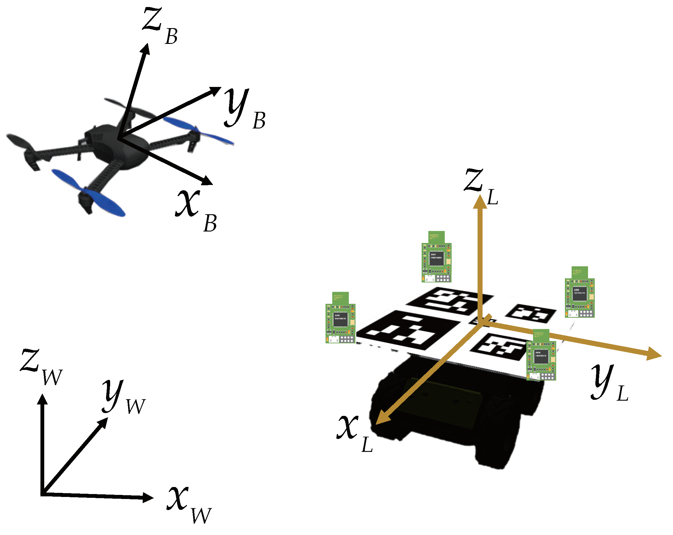
This study integrates a variety of sensors. Their respective coordinates are shown in Figure 1. In particular, the UAV body frame is fixed with the aerial vehicle. The landmark frame is fixed with the mobile platform which carries the custom designed markers and UWB station. Both of them are defined in forward-left-up(FLU) format, i.e., the x-axis is aligned with the forward moving direction, the y-axis is aligned left, and the z-axis is determined by the right-hand rule. An East-North-Up (ENU) coordinate is defined as the world frame.

2.1. Problem Formulation

During autonomous landing, the UAV can be guided to the landmark by position and velocity control. A flight controller is designed to precisely track the control references. The UAV locomotion can be modeled by
p b ( k + 1 ) = p b ( k ) + T v b ( k )
where p b ( k ) = p b x , p b y , p b z R 3 is the position of the UAV in the world frame, T is the control period, and v b ( k ) = v b x , v b y , v b z is the velocity control input.
Similar to the UAV, the motion of the ground platform can be modeled as:
p l ( k + 1 ) = p l ( k ) + T v l ( k )
where p l ( k ) = p l x , p l y , p l z R 3 is the position of the ground mobile platform in the world frame, and v l ( k ) = v l x , v l y , v l z is the velocity of the ground mobile platform. Since the mobile platform is moving on the ground, its height variation is assumed as constant, and the velocity on the z-axis is zero.
The velocity control input of the UAV in the x-y plane can be obtained by a feed-forward proportional-integral-derivative (PID) controller:
v b x ( k ) = v l x ( k ) + K p x ( p l x ( k ) p b x ( k ) ) v b y ( k ) = v l y ( k ) + K p y ( p l y ( k ) p b y ( k ) )
where K p x , K p y R are the control gains. According to the latter experimental results, with the fine-tuned control gains, the proposed PID law matches the accuracy requirements of approaching and landing control.

2.2. UWB-IMU-Vision-Based Pose Estimation

The accuracy of position and velocity estimation of the ground platform is essential for the UAV landing. The position of the ground platform in the world coordinate can be obtained by
p l = p b R W L p b L
where R W L is the rotation matrix from the world frame to the landmark frame which can be obtained by the onboard IMU of the mobile platform, and p b L is the relative position of the UAV in the landmark frame which can be obtained from vision estimation and the UWB measurements. As the state of the UAV in the world frame can be obtained by the onboard sensors (GPS and IMU), the state of the ground mobile platform can be estimated by measuring the relative motion state between the air and ground vehicles.
In such cases, the UWB can provide the X-Y position estimation under a relatively low sampling rate with some occasional outliers. A typical example is shown in Section 3.1. To address the shortcomings of UWB, relative acceleration was taken into consideration to provide high-frequency motion estimation. Under the assumption of the constant moving velocity of the ground platform, the relative acceleration of the UAV can be obtained accordingly by the projection of the acceleration of the UAV in the body frame to the mobile platform, which is given by
a b L = R L B a b B
where a b L R 3 is the acceleration of UAV in the mobile platform, R L B is the rotation matrix from the UAV body coordinate to the mobile platform coordinate, and a b B R 3 is the acceleration measured by the IMU of the UAV.
The attitude of the UAV in world coordinates can be estimated by the onboard IMU. In addition, the roll and pitch angle of the ground mobile platform is nearly zero. Then, R L B is the function of the orientation of the ground platform. The IMU can also be applied on ground platforms for orientation estimation. In addition, extracting relative orientation using a custom-defined landmark from the UAV’s vision sensor is a reliable alternative, which can avoid the disturbances of electromagnetic interference.
From the above discussion, in order to improve the effectiveness, reliability, and stability of the autonomous landing system and ensure continuous and stable tracking of the landing platform throughout the landing mission, relative pose estimation was provided by using three kinds of sensors - UWB, IMU, and vision location. The UWB-IMU was integrated to provide real-time relative position estimation, and the vision sensor was adopted to provide reliable relative pose estimation.

2.3. Landing Scheme Work Flow

The overall configuration of the proposed landing scheme is composed of a moving ground vehicle carrying a custom-designed landmark with four UWB stations fixed in the corner of the landing pad. The UAV carries a downward camera to capture the landmark and a UWB label to estimate the relative position between the UAV and the moving vehicle. As shown in Figure 2, The autonomous landing scheme is mainly divided into two stages: the approaching stage and the landing stage. In the approaching stage, when the autonomous landing mission starts, the UAV is far from the landing platform, the visual information is unreachable, and the pose estimation from vision cannot be provided. Therefore, the UAV obtains the relative position between the UAV and the ground mobile platform mainly relying on the UWB-IMU fusion positioning system, and the relative orientation is estimated by their onboard IMU. In addition, the UAV will remain at a certain height at this stage to have a wide field of vision for detecting the landmark. When the UAV is close to the landing platform and the visual information is captured, the UAV enters the landing stage based on the pose provided by both visual information and the UWB-IMU location system. At this stage, the UAV relies on UWB-IMU fusion positioning information to provide the relative position and velocity estimation of the mobile platform. The relative orientation is precisely tracked based on the visual information.

3. UWB-IMU-Based Localization in Approaching Stage

3.1. The Limitation of UWB-Based Position Estimation

UWB is a sensor that can provide range measurement information between each UWB anchor. In most cases, the UWB positioning method has higher positioning accuracy in the X-Y plane, while it can only provide position measurement with a low frequency (about 3–4 Hz). In addition, the location accuracy is affected by a non-line-of-sight error (NLOS), i.e., the object occlusion between UWB modules. Such errors induce outliers in UWB readings.
An experiment was conducted to evaluate the performance of UWB-based relative position estimation. As shown in Figure 3, four UWB anchors were placed on the corner of the landing pad, and a UWB label was carried by the flying UAV for localization. To validate the reliability of the UWB readings, we used a motion capture system—Optitrack—to provide ground truth. Optitrack is widely used to track objects with the accuracy up to sub-millimeter resolution at high sensing frequency. Camera-mounted strobes illuminate small, retro-reflective markers, which are identified and processed to extract the high precision position and attitude of the objects. The Optitrack cameras tracked reflective markers on the UAV to obtain precise position data, which was then compared to the UWB result for validation.
A typical localization result of UWB is shown in Figure 4. Based on Figure 4, although the UWB measurement is barely consistent with the real flight trajectory, it demonstrates low consistency performance and unsmooth sensing results. Moreover, the outliers, as labeled in the blue square, increase the flight risk greatly and are not conducive to the completion of the flight mission. In this experiment, the mean localization error of UWB is 1.020 m and 0.617 m along the x-axis and y-axis, respectively. As a result, using UWB alone is unreliable for vehicle localization, and its precision is severely affected by the outliers of the UWB system.

3.2. UWB-IMU Position Estimation

As discussed above, due to the low update rate and outliers of UWB sensing, the position estimated by UWB is difficult for guaranteeing the smoothness and consistency. Therefore, the acceleration information provided by the IMU was taken into account. An EKF-based UWB-IMU sensor fusion algorithm is proposed to improve the sensing accuracy and boost the sampling frequency. Particularly, the proposed UWB-IMU sensory system was applied to estimate the relative position between the air and ground platforms in the mobile platform coordinate.
In the proposed EKF-based UWB-IMU localization algorithm, the acceleration from the IMU of the UAV a x B , a y B , a z B is taken as the input vector of the state equation. The state vector of the EKF state equation is composed of the three-dimensional relative positions and velocities of the UAV in the mobile platform coordinate. What is more, the noise of the IMU is relatively large in the practical application, and the acceleration bias is affected by various factors, such as temperature and mechanical vibration, leading to a serious drift for integration directly from the measurement of the IMU accelerometer. In order to solve the position drift, the acceleration deviations are considered into state vectors:
x = p x r , p y r , p z r , v x r , v y r , v z r , a b i a s x r , a b i a s y r , a b i a s z r
where p x r , p y r , p z r and v x r , v y r , v z r are the three-dimensional relative positions and velocities of the UAV in the mobile platform coordinate, and a b i a s x r , a b i a s y r , a b i a s z r is the bias of the acceleration of the UAV in the mobile platform coordinate.
Since the acceleration information from the IMU of the UAV is the acceleration measurements of the UAV in its body coordinate system, it is essential to estimate the relative orientation between the UAV and the landmark and project the acceleration of the body frame to the landmark coordinate system as we discussed in Section 2.2. In the approaching stage, the relative orientation is obtained by the IMU measurement of the UAV and the IMU measurement from the mobile platform. In the landing stage, a more accurate yaw estimation is provided by the vision pose extraction described in Section 4. With the estimated relative orientation, the relative acceleration of the UAV can be projected according to the attitude angle of the UAV in the platform coordinate system, and the rotation matrix is set as R L B . The state equation can be obtained as:
x ˙ = Ax + R L B Bu + w A = 1 0 0 T 0 0 T 2 2 0 0 0 1 0 0 T 0 0 T 2 2 0 0 0 1 0 0 T 0 0 T 2 2 0 0 0 1 0 0 T 0 0 0 0 0 0 1 0 0 T 0 0 0 0 0 0 1 0 0 T 0 0 0 0 0 0 1 0 0 0 0 0 0 0 0 0 1 0 0 0 0 0 0 0 0 0 1 B = T 2 2 0 0 0 T 2 2 0 0 0 T 2 2 T 0 0 0 T 0 0 0 T 0 0 0 0 0 0 0 0 0 u = a x B , a y B , a z B
In order to construct the observation matrix of the EKF estimator, the distances between each anchor on the landing pad and the onboard UWB label of the UAV are measured as observations. The observed variable of the observation equation is the error between the measured distance of UWB and the predicted distance estimated from the state equation. The relative position of the UAVs is set as p x r , p y r , p z r . Then, the distance between the UAV and the i-th UWB station is:
d i = p x r P x i 2 + p y r P y i 2 + p z r P z i 2
At the same time, based on the state equation, Equation (7), the posterior estimated value of the position of the UAV in the platform coordinate system is p ˜ x r , p ˜ y r , p ˜ z r , and the distance information between the UAV and the i-th UWB base station installed on the landing platform should be:
d i = p ˜ x r P x i 2 + p ˜ y r P y i 2 + p ˜ z r P z i 2
Here, first-order Taylor expansion was applied to Equation (8) at p ˜ x r , p ˜ y r , p ˜ z r , and we obtain:
D i = d i + d i p ˜ x r d p x r + d i p ˜ y r d p y r + d i p ˜ z r d p z r d i p ˜ x r = p ˜ x r P x i d i d i p ˜ y r = p ˜ y r P y i d i d i p ˜ z r = p ˜ z r P z i d i
Subtracting the distance estimated from the equation of state from the measured distance:
Δ d i = d i p ˜ x r d p x r + d i p ˜ y r d p y r + d i p ˜ z r d p z r + v i
Then, the observation equation is:
Z = Hx + v Z = d 1 d 2 d n H = d 1 p ˜ x d 1 p ˜ y d 1 p ˜ z 0 0 d 2 p ˜ x d 2 p ˜ y d 2 p ˜ z 0 0 d n p ˜ x d n p ˜ y d n p ˜ z 0 0 0 n N
Here n is the number of the UWB stations, and N is the dimension of the state vector.
Due to the instability of the readings of the UWB sensor, even the measured distance can be accurate to the centimeter level in most cases, while occasionally, the measured distance is completely wrong due to the influence of the complex environment, which will lead to a sharp increase in estimate errors. At the same time, the IMU readings are also quite noisy, especially when the micro UAV is moving slowly, which means that it is impractical to rely too much on the IMU. Therefore, when adjusting the covariance matrices Q and R, the choice tends to rely more on UWB readings. In order to alleviate the abrupt outlier measurements from UWB, the distance estimated according to the state equation is used to compare with the measured value of the UWB sensors in the update stage of EKF. If the error exceeds a certain threshold, the current measurement of UWB is discarded, and the position continues to be predicted according to the state equation until the next UWB range measurement is updated.
With the IMU-based prediction step and the UWB-based update step, the proposed method can eliminate the shortage of the IMU integral cumulative error and the occasional jump out of the UWB range measurements, making the positioning result smoother and more reliable. In addition, the EKF can also increase the localization frequency to make up for the low frequency of UWB measurements. As shown in Figure 5, the red line represents the UWB measurement information, and the black one is IMU information. When the UWB range measurement is available, normal prediction and update steps are performed based on the EKF. When UWB range measurement is unavailable, IMU information is used for forecasting the position estimation. Due to the high frequency of IMU measurement release, the fusion positioning algorithm can improve the positioning frequency while maintaining accuracy so that the UAV can obtain real-time perception information when maneuvering quickly.

4. Vision-Based Relative Pose Estimation in Landing Stage

4.1. Landmark Design and Detection

For the specific task of autonomous landing, specific visual cooperation signs need to be designed to achieve stable target tracking in the process of autonomous landing. As discussed above, in the proposed UWB-IMU-vision position estimation, relative orientation is the essential information for calculating the relative acceleration of the UAV in the mobile platform coordinate. Therefore, it is necessary to develop visual cooperation signs which can provide reliable attitude estimation, especially orientation estimation.
To assess the relative orientation of the UAV accurately, a novel landmark consisting of five independent ArUco markers in varied sizes was devised as shown in Figure 6a. Such a design can be employed for relative attitude estimation of the UAV and efficient identification at different altitudes. When the whole landmark is within the camera’s FOV, relative pose estimation is conducted using the four outer markers. When the UAV is approaching the landmark, the outer marker is not visible in the camera field of view, and the marker in the center can continue to guide the UAV to descend and land on the moving platform.
In order to satisfy the real-time requirements of the target detection algorithm in autonomous landing, the YoloV4-tiny detector [20] was adopted to detect each ArUco marker and estimate the bounding box coordinates. A custom dataset was collected using our actual landing pad to ensure reliable detection accuracy. Image augmentation was applied to expand the dataset’s size, including horizontal and vertical shifts, random zoom and rotation, and brightness adjustment to improve the stability of detection in any possible scenarios. The coordinates of these bounding boxes were then used to calculate the relative pose between the UAV and mobile platform.

4.2. Relative Orientation Estimation

The yaw angle estimation was acquired for the designed landmark by locating the outer markers. As shown in Figure 6a, the external markers can be divided into two groups according to their size: large markers and small markers. At the same time, their centroid coordinates in the image can be obtained during the detection process. Then, two parallel guidelines were obtained by matching the center of two large markers and small markers. After that, the direction vector of the landing pad was defined by the middle point of these two guidelines, and the angle between the direction vector aligns the x w -axis defined as the yaw angle.
As shown in Figure 6a, the outer four marker points were marked 1, 2, 3, and 4 in counterclockwise order. When the UAV can recognize four external markers, the centroid coordinates of each marker in the image pixel can be obtained, which means we have four 3D points of each marker in the landmark coordinate and their corresponding 2D projections in the image pixel coordinate. The relative transformation matrix between the UAV camera frame and the landing platform T L C can be obtained by solving the perspective-n-point (PnP) problem using the well-known Levenberg–Marquardt (LM) algorithm [21] to minimize the reprojection error.
Due to the existence of disturbance or when the UAV is near the landing platform, the external markers may lose detection. At that time, the UAV will perform an image-based visual servo landing by keeping the center mark in the center of vision using pixel error. During this time, the UAV will eliminate its horizontal position error with the landmark and descent. If the landmark tracking fails when the UAV suffers abrupt disturbances such as gusts, the UAV will return to the search stage to fly up when the visual tracking information is lost. With the proposed scheme, the UAV will finally land on the mobile platform autonomously.

5. Sensing Performance Validation

5.1. Localization Performance When UAV Approaching

In the approaching stage, the UWB-IMU system mainly handles the localization of the UAV. Since the accuracy of UWB readings is affected by various factors, it is necessary to model and calibrate the UWB modules. We first collected the UWB measurement results at certain distances, e.g., 2 m, 3 m, 4 m, and 5 m, and the stationary ranging results were analyzed after thousands of measurements at each distance. Taking the measurement at 3 m distance as an example, the distribution of the results is shown in Figure 7a, which approximately fits with the normal distribution. As shown in Figure 7b, after analyzing the UWB measurement accuracy, the average error is within 5 cm, and the standard deviation of the error is about 2 cm. Such a result indicates that the UWB module follows the normal distribution model and has centimeter-level ranging accuracy in stationary measurements without disturbances.
A comparative study was conducted to evaluate the performance improvement by the UWB-IMU fusion. As shown in Figure 8, when most of the UWB measurements are normal, the results of the two positioning algorithms are fairly consistent. Nevertheless, using UWB alone may cause large sensing deviation due to the unexpected environmental disturbances, which generate ridiculous outliers as shown in the red box in Figure 8. Benefiting from the EKF, the UWB-IMU fusion method is not affected by the abnormal measurement of UWB and maintains overall reliable positioning accuracy. Such a sensor fusion method can effectively address localization outliers of UWB measurements.

5.2. Pose Estimation Performance in Landing Stage

Similar to the approaching stage test, we used the Optitrack system again to provide ground truth in a vision-dominated pose estimation test. As shown in Figure 3, the Optitrack cameras track reflective markers on both the UAV and the landing pad to obtain precise position and orientation data. To examine the performance of the proposed vision position and orientation estimation algorithm, the open-source and state-of-the-art fiducial marker—Fractal ArUco [9]—landmark was used as the baseline algorithm. Based upon a typical ArUco marker, the proposed landmark group can aid the vision system in orientation estimation.
To verify the reliability of the proposed pose estimation method, an experiment was conducted. The data were collected by a UAV with an onboard camera. During the test, the UAV was flown at about 1 m above the landmark. The yaw angle estimation result and the position estimation results in the horizontal plane are shown in Figure 9. The proposed method can obtain high accuracy in the wide range yaw angle estimation, and the position can be estimated accurately in a small error with the proposed relative pose estimation algorithm.
To illustrate the accuracy of the proposed method, we compared the pose estimation result of the proposed method with Fractal ArUco [9]. The result is shown in Figure 10. It can be clearly seen that in yaw estimation, not only is the average estimation error of the proposed method much smaller than that of the method based on the Fractal ArUco library, but the standard deviation is also much smaller. This indicates that the pose estimation results based on Fractal ArUco are less reliable and unsuitable for the UAVs to track the yaw direction of the landmark. Using the proposed method, the UAV can track the landmark in the yaw direction with relatively small errors and concentrated error distribution.

6. Simulation and Real-World Experiments

6.1. Simulation Tests

In order to verify the proposed systematic landing scheme in this paper, an autonomous landing simulation test was carried out. The proposed scheme was tested in Gazebo simulator with an Intel Core i5-8400 2.8 GHz CPU. A 3DR Iris UAV with a down-facing camera, and an unmanned ground vehicle carrying the landing pad were selected as the test platform, as shown in Figure 11.
Since the distance measurement of the UWB module cannot be simulated in Gazebo, the UWB range measurement of the anchor on UAV with each base station on the mobile platform was obtained by adding the random noise with the Gaussian distribution to their real measurement in the simulator. The variance of the random noise was set to 10 cm according to the experiment result provided in Section 5.1. With this setup, the UAV autonomous landing experiment was carried out. The initial position between the UAV and the mobile platform was set to be 0 m on the x-axis and 5 m on the y-axis, and the initial yaw angle between the mobile platform and the UAV were set randomly. After the UAV takes off and stands by, the ground mobile platform starts to move in a fixed direction at a speed of 0.5 m/s and the autonomous landing mission starts.
The landing trajectory is shown in Figure 12. The UAV approached the mobile platform guided by the UWB-IMU position estimation until the landmark was detected. Then, the UAV began to descend and kept tracking the motion of the mobile platform. Figure 13 and Figure 14 show the position and velocity changes of the UAV and the moving platform during the autonomous landing process. As can be seen, the UAV eliminated the position error in a short time and kept tracking the mobile platform and descending.

6.2. Real-World Experiments

In order to verify the feasibility and precision of the autonomous landing system scheme, an outdoor real-world flight experiment was carried out. Figure 15 shows the UAV used in this experiment. The onboard equipment included a Pixhawk 4 mini flight control unit running PX4 autopilot [22], a GPS sensor equipped to provide the position localization of the UAV in the world coordinate, a monocular camera for vision detection, a UWB label for relative position localization, a JETSON XAVIER NX onboard computer, and a TFmini laser ranging unit. The UGV carried a landmark with a size of 0.8 × 0.8 m, and four UWB base stations were arranged at each corner of the landmark.
Figure 16 and Figure 17 show the landing trajectory of the UAV during autonomous landing. As can be seen from Figure 16, the UAV can land autonomously with the guidance of the proposed landing scheme. The blue dashed line shows the flight trajectory of the UAV guided by the proposed method during the landing process, and the red line is the trajectory of the UAV gradually stopping the propeller and landing on the landing pad when the UAV reaches the given threshold. Figure 18 shows the variation of the estimated position between the UAV and the landmark in the landing process. It can be seen that at the beginning of the mission, the UAV gradually approaches the landmark by means of UWB-IMU positioning. When the camera of the UAV captures the landing pad and the relative position and precision orientation estimation can be estimated from the vision sensors, the UAV keeps approaching the landing platform depending on the UWB-IMU-vision localization. However, with the disturbance of the external environment, the UAV will sometimes offset and lose detection of some outer landmarks, and the pixel error of the UAV is used to control the UAV to change the landing mark back to the camera view and regain the visual pose estimation. After the distance between the UAV and the landing pad in the horizontal direction meets the given threshold, the UAV starts to descend and maintains the dynamic adjustment in the horizontal direction until both the altitude requirement and the horizontal position are finally satisfied. Then, the UAV will lower its throttle to zero in a short time and complete the landing mission. As shown in Figure 18, the proposed method can out perform the accuracy in an autonomous landing mission. The landing error is within 10 cm in the horizontal direction. The final landing precision is 0.06 m in the x-axis and 0.05 m in the y-axis.

7. Conclusions

In this study, an autonomous landing solution for UAV autonomous landing task requirements was proposed. A UWB-IMU-vision-based relative localization algorithm was proposed to provide the position estimation of the UAV with high frequency and accuracy. To obtain an accurate estimation of the relative orientation between the UAV and the mobile platform, a novel landmark composed of an ArUco marker bundle was designed, a deep-learning-based detection algorithm and pose extraction algorithm were adapted accordingly. The systematic landing scheme integrates the aforementioned state estimation algorithm that was developed for the UAV to land on the mobile platform autonomously. Based on flight tests, the UAV can successfully perform autonomous landings with the proposed scheme. In the future, we will extend the proposed design in this work to further study the landing trajectory generation in cluttered environments.

Author Contributions

Conceptualization, Z.T. and X.D.; methodology, Z.T., X.D. and S.Z.; software, X.D. and J.G.; validation, J.G. and Y.G.; formal analysis, X.D.; investigation, J.G. and Y.G.; resources, D.L.; data curation, J.G. and Y.G.; writing—original draft preparation, X.D.; writing—review and editing, Z.T. and Y.G.; visualization, X.D.; supervision, D.L. and J.X.; project administration, Z.T. and J.X.; funding acquisition, Z.T. and D.L. All authors have read and agreed to the published version of the manuscript.

Funding

This research was funded by the National Key Research and Development Project of China, grant numbers 2020YFC1512500.

Institutional Review Board Statement

Not applicable.

Informed Consent Statement

Not applicable.

Data Availability Statement

Not applicable.

Acknowledgments

The authors would like to express our thanks to the editors and reviewers for contributing to the final form of this research.

Conflicts of Interest

The authors declare no conflict of interest.

References

  1. Cesetti, A.; Frontoni, E.; Mancini, A.; Zingaretti, P.; Longhi, S. A Vision-Based Guidance System for UAV Navigation and Safe Landing using Natural Landmarks. J. Intell. Robot. Syst. 2010, 57, 233. [Google Scholar] [CrossRef]
  2. Fiala, M. ARTag, a fiducial marker system using digital techniques. In Proceedings of the 2005 IEEE Computer Society Conference on Computer Vision and Pattern Recognition (CVPR’05), San Diego, CA, USA, 20–25 June 2005; pp. 590–596. [Google Scholar] [CrossRef]
  3. Olson, E. AprilTag: A robust and flexible visual fiducial system. In Proceedings of the 2011 IEEE International Conference on Robotics and Automation, Shanghai, China, 9–13 May 2011; pp. 3400–3407. [Google Scholar] [CrossRef] [Green Version]
  4. Wang, J.; Olson, E. AprilTag 2: Efficient and robust fiducial detection. In Proceedings of the 2016 IEEE/RSJ International Conference on Intelligent Robots and Systems (IROS), Daejeon, Republic of Korea, 9–14 October 2016; pp. 4193–4198. [Google Scholar] [CrossRef]
  5. Krogius, M.; Haggenmiller, A.; Olson, E. Flexible layouts for fiducial tags. In Proceedings of the 2019 IEEE/RSJ International Conference on Intelligent Robots and Systems (IROS), Macau, China, 3–8 November 2019; pp. 1898–1903. [Google Scholar] [CrossRef]
  6. Garrido-Jurado, S.; Muñoz-Salinas, R.; Madrid-Cuevas, F.J.; Marín-Jiménez, M.J. Automatic generation and detection of highly reliable fiducial markers under occlusion. Pattern Recognit. 2014, 47, 2280–2292. [Google Scholar] [CrossRef]
  7. Garrido-Jurado, S.; Muñoz-Salinas, R.; Madrid-Cuevas, F.J.; Medina-Carnicer, R. Generation of fiducial marker dictionaries using mixed integer linear programming. Pattern Recognit. 2016, 51, 481–491. [Google Scholar] [CrossRef]
  8. Romero-Ramirez, F.J.; Muñoz-Salinas, R.; Medina-Carnicer, R. Speeded up detection of squared fiducial markers. Image Vis. Comput. 2018, 76, 38–47. [Google Scholar] [CrossRef]
  9. Romero-Ramire, F.J.; Muñoz-Salinas, R.; Medina-Carnicer, R. Fractal Markers: A New Approach for Long-Range Marker Pose Estimation Under Occlusion. IEEE Access 2019, 7, 169908–169919. [Google Scholar] [CrossRef]
  10. Babinec, A.; Jurišica, L.; Hubinskỳ, P.; Duchoň, F. Visual localization of mobile robot using artificial markers. Procedia Eng. 2014, 96, 1–9. [Google Scholar] [CrossRef]
  11. Kalaitzakis, M.; Cain, B.; Carroll, S.; Ambrosi, A.; Whitehead, C.; Vitzilaios, N. Fiducial markers for pose estimation. J. Intell. Robot. Syst. 2021, 101, 1–26. [Google Scholar] [CrossRef]
  12. Liu, X.; Zhang, S.; Tian, J.; Liu, L. An onboard vision-based system for autonomous landing of a low-cost quadrotor on a novel landing pad. Sensors 2019, 19, 4703. [Google Scholar] [CrossRef] [PubMed] [Green Version]
  13. Araar, O.; Aouf, N.; Vitanov, I. Vision based autonomous landing of multirotor UAV on moving platform. J. Intell. Robot. Syst. 2017, 85, 369–384. [Google Scholar] [CrossRef]
  14. Palafox, P.R.; Garzón, M.; Valente, J.; Roldán, J.J.; Barrientos, A. Robust visual-aided autonomous takeoff, tracking, and landing of a small UAV on a moving landing platform for life-long operation. Appl. Sci. 2019, 9, 2661. [Google Scholar] [CrossRef] [Green Version]
  15. Cheng, C.; Li, X.; Xie, L.; Li, L. Autonomous dynamic docking of UAV based on UWB-vision in GPS-denied environment. J. Frankl. Inst. 2022, 359, 2788–2809. [Google Scholar] [CrossRef]
  16. Nguyen, T.M.; Nguyen, T.H.; Cao, M.; Qiu, Z.; Xie, L. Integrated UWB-Vision Approach for Autonomous Docking of UAVs in GPS-denied Environments. In Proceedings of the 2019 International Conference on Robotics and Automation (ICRA), Montreal, QC, Canada, 20–24 May 2019; pp. 9603–9609. [Google Scholar] [CrossRef]
  17. Xia, K.; Shin, M.; Chung, W.; Kim, M.; Lee, S.; Son, H. Landing a quadrotor UAV on a moving platform with sway motion using robust control. Control Eng. Pract. 2022, 128, 105288. [Google Scholar] [CrossRef]
  18. Ochoa-de Eribe-Landaberea, A.; Zamora-Cadenas, L.; Peñagaricano-Muñoa, O.; Velez, I. UWB and IMU-Based UAV’s Assistance System for Autonomous Landing on a Platform. Sensors 2022, 22, 2347. [Google Scholar] [CrossRef] [PubMed]
  19. Kim, C.; Lee, E.M.; Choi, J.; Jeon, J.; Kim, S.; Myung, H. ROLAND: Robust Landing of UAV on Moving Platform using Object Detection and UWB based Extended Kalman Filter. In Proceedings of the 2021 21st International Conference on Control, Automation and Systems (ICCAS), Jeju, Republic of Korea, 12–15 October 2021; pp. 249–254. [Google Scholar] [CrossRef]
  20. Bochkovskiy, A.; Wang, C.Y.; Liao, H.Y.M. YOLOv4: Optimal Speed and Accuracy of Object Detection. arXiv 2020, arXiv:2004.10934. [Google Scholar]
  21. Lu, C.P.; Hager, G.; Mjolsness, E. Fast and globally convergent pose estimation from video images. IEEE Trans. Pattern Anal. Mach. Intell. 2000, 22, 610–622. [Google Scholar] [CrossRef]
  22. Meier, L.; Honegger, D.; Pollefeys, M. PX4: A node-based multithreaded open source robotics framework for deeply embedded platforms. In Proceedings of the 2015 IEEE International Conference on Robotics and Automation (ICRA), Seattle, WA, USA, 26–30 May 2015; pp. 6235–6240. [Google Scholar] [CrossRef]
Figure 1. Coordinates definition of UAV autonomous landing scenario.
Aerospace 09 00797 g001
Figure 2. Workflow of the proposed landing scheme.
Aerospace 09 00797 g002
Figure 3. Illustration of the UWB flight localization experiment setup.
Aerospace 09 00797 g003
Figure 4. A typical UAV flight trajectory measured by UWB.
Aerospace 09 00797 g004
Figure 5. Framework of UWB-IMU fusion method.
Aerospace 09 00797 g005
Figure 6. Yaw estimation principle of the customized landmark: (a) example of numbering the marker; (b) the definition of the yaw angle.
Aerospace 09 00797 g006
Figure 7. UWB calibration test: (a) distribution of the estimated position at 3 m distance; (b) position estimation error in different distances.
Aerospace 09 00797 g007
Figure 8. Position estimate result between UWB and UWB-IMU fusion.
Aerospace 09 00797 g008
Figure 9. Comparison on yaw and position estimation between the proposed method and Fractal ArUco.
Aerospace 09 00797 g009
Figure 10. Position and orientation estimation error of proposed method between the proposed method and Fractal ArUco.
Aerospace 09 00797 g010
Figure 11. Simulated UAVs and mobile platform in Gazebo.
Aerospace 09 00797 g011
Figure 12. Trajectory of UAVs and mobile platform.
Aerospace 09 00797 g012
Figure 13. Position of the UAV and landing pad.
Aerospace 09 00797 g013
Figure 14. Velocity of the UAV and landing pad.
Aerospace 09 00797 g014
Figure 15. The UAV and its components.
Aerospace 09 00797 g015
Figure 16. Autonomous landing trajectory on a landing pad.
Aerospace 09 00797 g016
Figure 17. Overall autonomous landing experiment process.
Aerospace 09 00797 g017
Figure 18. Relative position estimated by the proposed method.
Aerospace 09 00797 g018
Publisher’s Note: MDPI stays neutral with regard to jurisdictional claims in published maps and institutional affiliations.

