Preliminary Analysis of Compression System Integrated Heat Management Concepts Using LH2-Based Parametric Gas Turbine Model
Abstract
:1. Introduction
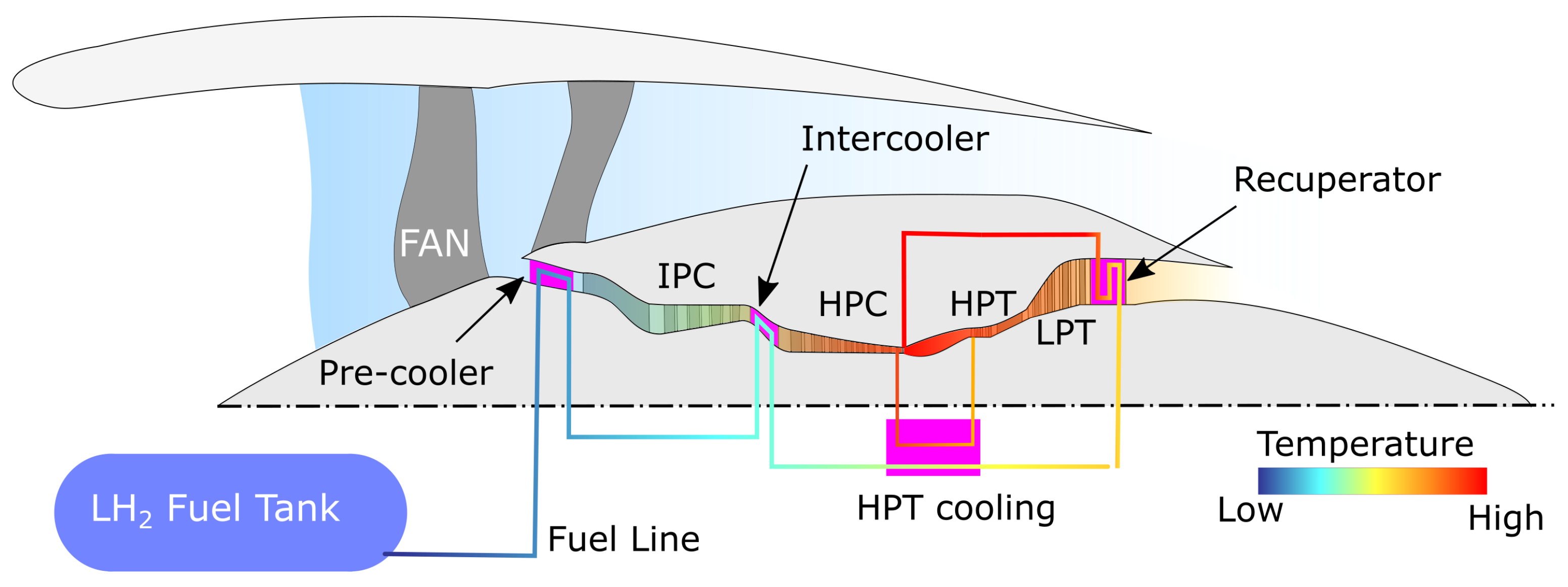
Heat Management Potential
- Pre-cooling: The precooler is located between the fan and intermediate-pressure compressor (IPC). It increases the fuel temperature before entering the combustion chamber and decreases the IPC and HPC work by cooling the core flow before compression.
- Intercooling: The intercooler is placed between the IPC and the high-pressure compressor (HPC). Similar to precooling, it raises the fuel temperature before entering the combustion chamber and reduces the HPC work by cooling the compressed airflow. Intercooling and precooling also enable an increase in core-specific work and allow for higher pressure ratios in the compression system before violating HPC discharge temperature limits. Another possible advantage arising for both pre- and intercooling is the possibility of reducing the combustor inlet temperature for a given OPR, which will curb NOx emissions. A challenge with both concepts is the risk of ice formation in the presence of humid air, which could cause a partial or complete blockage of the engine core flow.
- Cooled-cooling air: The main task of the high-pressure turbine (HPT) cooling is to reduce the temperature of the cooling air extracted from the HPC and used to cool the HPT. The potential is to improve the engine efficiency by reducing the amount of secondary air flows for a given turbine metal temperature limit.
- Recuperation: The recuperator is the main source of LH2 fuel heating before injection into the combustor. Among the other heat exchangers, it has the greatest potential for increasing the fuel temperature.
2. Engine Performance Simulation
- New combustion products tables are needed to complement conventional kerosene tables normally stored in performance codes;
- The integration of detailed modeling for the heat-management system as the cryogenic fuel flows from the tank to the combustor chamber;
- Means to model and manage heat between the fuel system and the propulsion system.
2.1. Combustion Modeling
2.2. Detailed Modeling of Real Gases
2.3. Modeling of Coupled Heat Management Systems
2.4. Fuel Distribution System
2.5. Quantifying Installation Effects
2.6. Heat Exchanger Performance and Conceptual Design
3. Results
3.1. Reference and Baseline Engines
3.2. Parametric Study
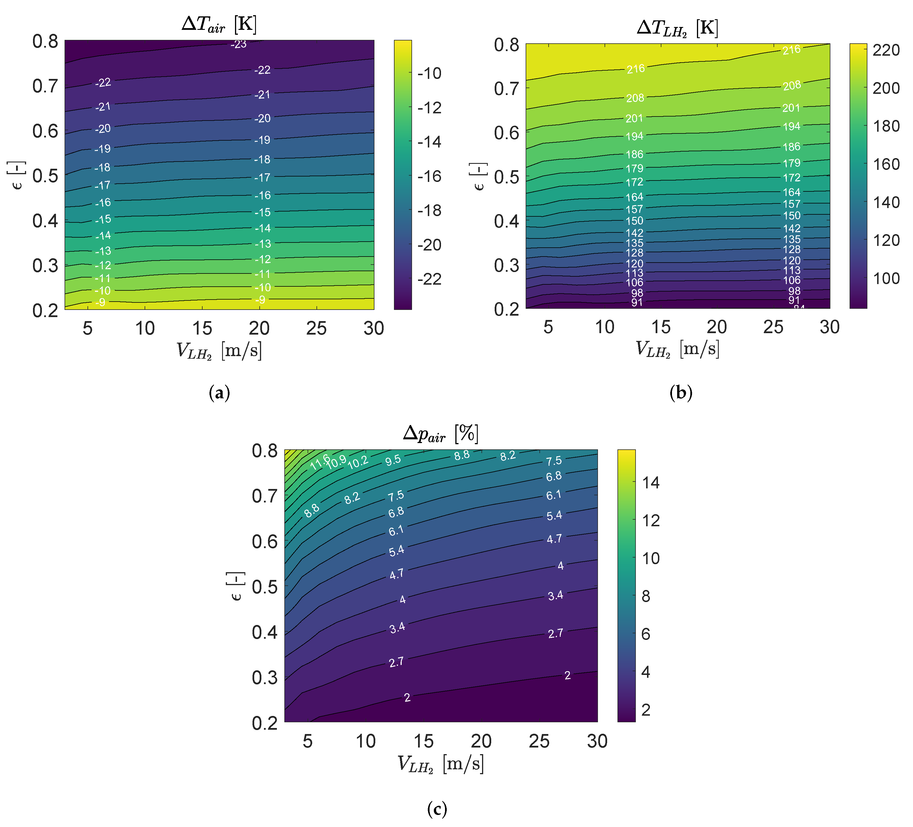
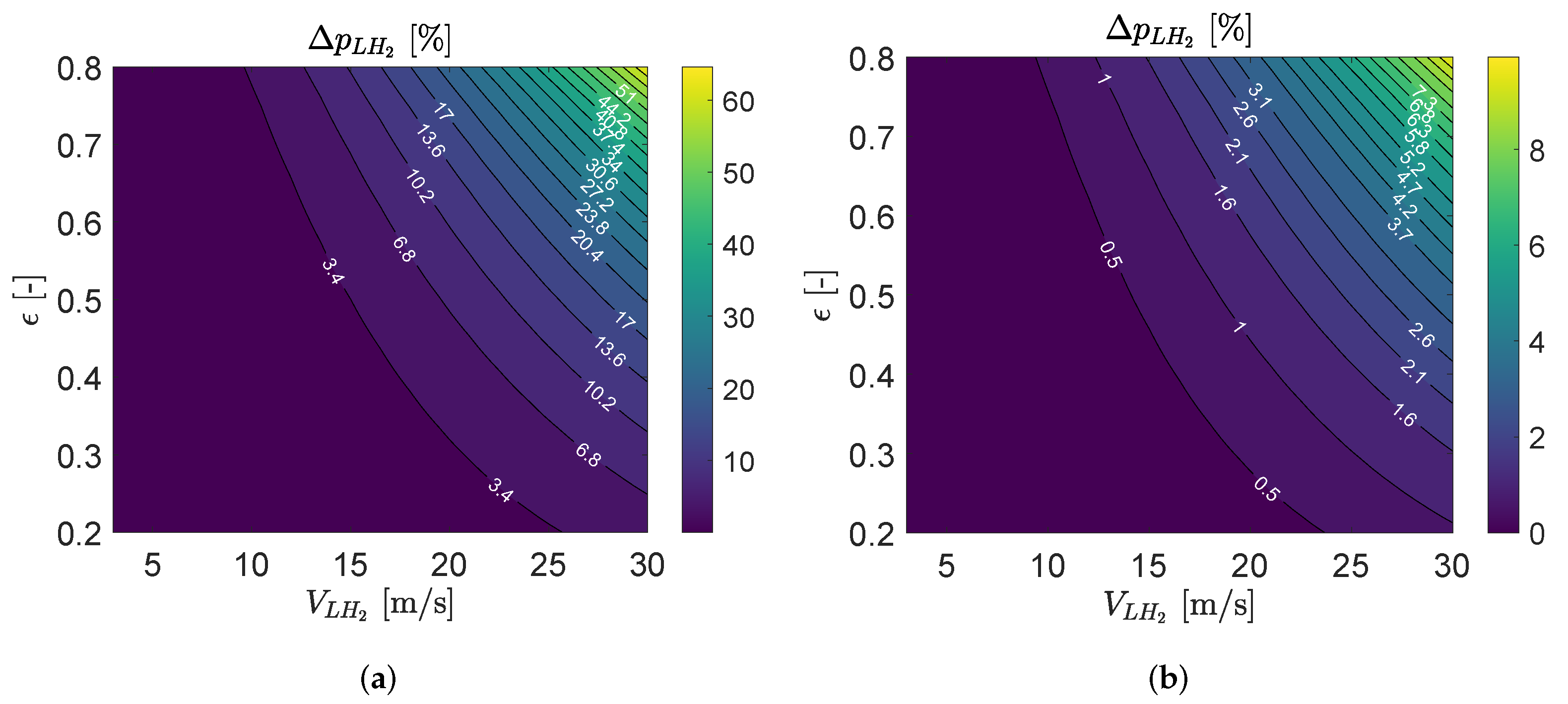
3.3. Precooler HE Performance
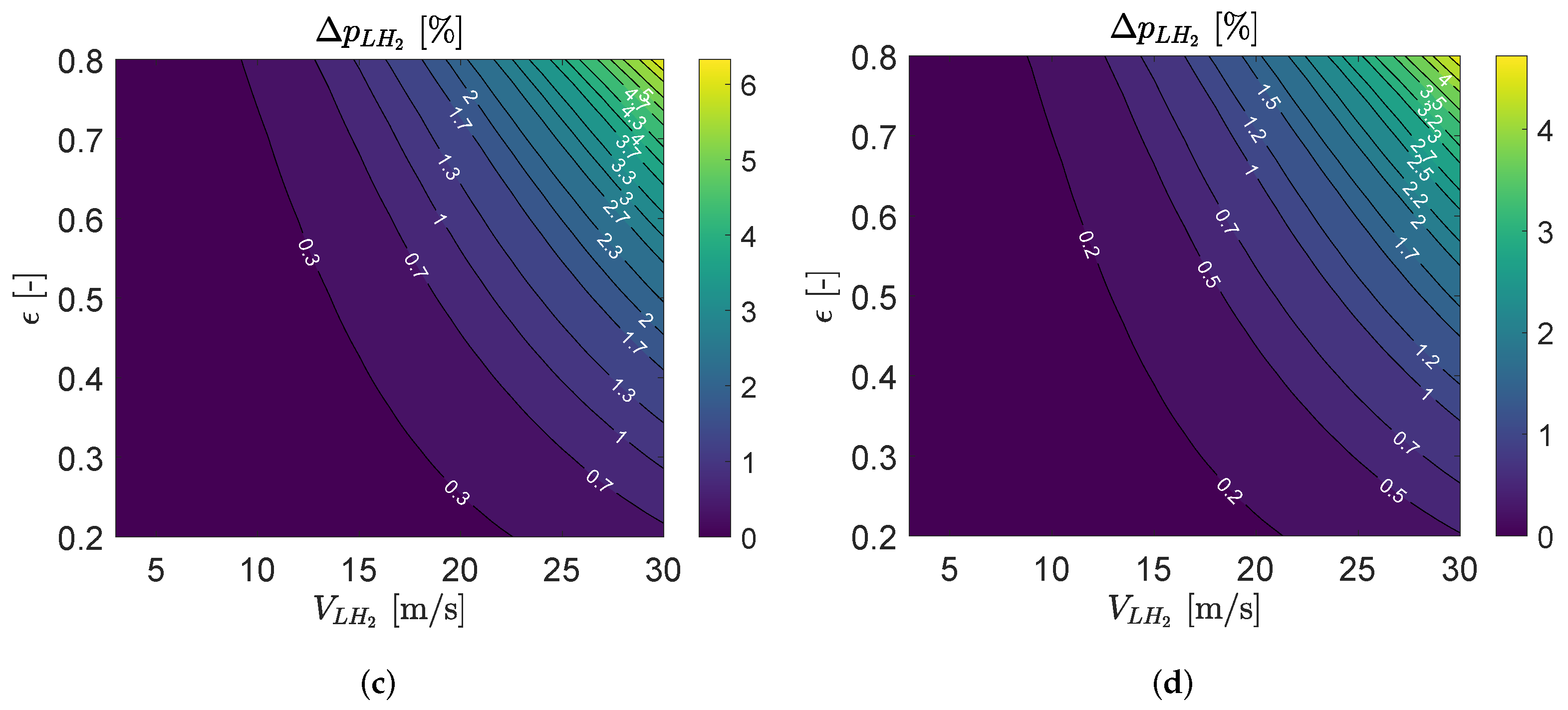
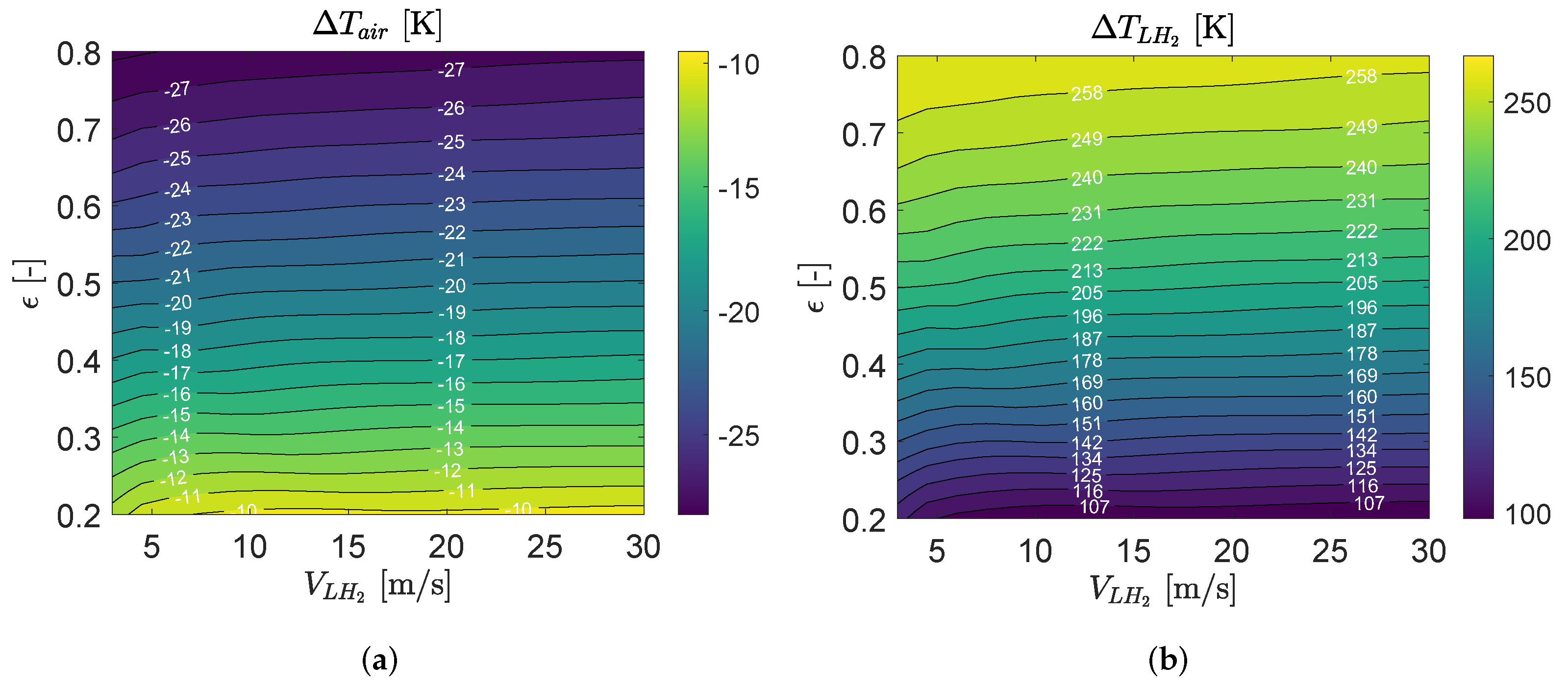
3.4. Intercooler HE Performance
4. Sensitivity Analysis of External Flow Mach Number on Precooler and Intercooler
5. Conclusions
Author Contributions
Funding
Conflicts of Interest
Nomenclature
| Abbreviation | Description |
| BPR | Bypass Ratio |
| FPR | Fan Pressure Ratio |
| HPC | High Pressure Compressor |
| HPT | High Pressure Turbine |
| ISA | International Standard Atmosphere |
| LPC | Low Pressure Compressor |
| LPT | Low Pressure Turbine |
| OPR | Overall Pressure Ratio |
| T4, TIT | Turbine Inlet Temperature |
| TSFC | Thrust-Specific Fuel Consumption |
| Efficiency | |
| Compressor Pressure Ratio | |
| Pump Pressure Ratio |
References
- Liu, Y.; Sun, X.; Sethi, V.; Nalianda, D.; Li, Y.G.; Wang, L. Review of modern low emissions combustion technologies for aero gas turbine engines. Prog. Aerosp. Sci. 2017, 94, 12–45. [Google Scholar] [CrossRef] [Green Version]
- Rao, A.G.; Yin, F.; Werij, H.G. Energy Transition in Aviation: The Role of Cryogenic Fuels. Aerospace 2020, 7, 181. [Google Scholar] [CrossRef]
- Grewe, V.; Gangoli Rao, A.; Grönstedt, T.; Xisto, C.; Linke, F.; Melkert, J.; Middel, J.; Ohlenforst, B.; Blakey, S.; Christie, S.; et al. Evaluating the climate impact of aviation emission scenarios towards the Paris agreement including COVID-19 effects. Nat. Commun. 2021, 12, 3841. [Google Scholar] [CrossRef] [PubMed]
- Srinath, A.N.; Pena López, Á.; Miran Fashandi, S.A.; Lechat, S.; di Legge, G.; Nabavi, S.A.; Nikolaidis, T.; Jafari, S. Thermal Management System Architecture for Hydrogen-Powered Propulsion Technologies: Practices, Thematic Clusters, System Architectures, Future Challenges, and Opportunities. Energies 2022, 15, 304. [Google Scholar] [CrossRef]
- Brewer, G.D. Hydrogen Aircraft Technology, 1st ed.; CRC Press: London, UK, 1991. [Google Scholar]
- Westenberger, A. Hydrogen Fueled Aircraft. In Proceedings of the AIAA International Air and Space Symposium and Exposition: The Next 100 Years, Dayton, OH, USA, 14–17 July 2003. [Google Scholar] [CrossRef]
- Jafari, S.; Nikolaidis, T. Thermal Management Systems for Civil Aircraft Engines: Review, Challenges and Exploring the Future. Appl. Sci. 2018, 8, 2044. [Google Scholar] [CrossRef] [Green Version]
- Green, J.E. Greener by Design—The technology challenge. Aeronaut. J. 2002, 106, 57–113. [Google Scholar]
- Verstraete, D. The Potential of Liquid Hydrogen for Long Range Aircraft Propulsion. Ph.D. Thesis, Cranfield University, Cranfield, UK, 2009. [Google Scholar]
- Khandelwal, B.; Karakurt, A.; Sekaran, P.R.; Sethi, V.; Singh, R. Hydrogen powered aircraft: The future of air transport. Prog. Aerosp. Sci. 2013, 60, 45–59. [Google Scholar] [CrossRef]
- Klug, H.G.; Faass, R. CRYOPLANE: Hydrogen fuelled aircraft—Status and challenges. Air Space Eur. 2001, 3, 252–254. [Google Scholar] [CrossRef]
- Svensson, F.; Singh, R. Effects of Using Hydrogen on Aero Gas Turbine Pollutant Emissions, Performance and Design. In Proceedings of the Expo 2004, Turbo Expo: Power for Land, Sea, and Air, Vienna, Austria, 14–17 June 2004; Volume 2, pp. 107–116. [Google Scholar] [CrossRef]
- Rogers, H.L.; Lee, D.S.; Raper, D.W.; Foster, P.M.D.F.; Wilson, C.W.; Newton, P.J. The impacts of aviation on the atmosphere. Aeronaut. J. 2002, 106, 521–546. [Google Scholar] [CrossRef]
- Haglind, F.; Hasselrot, A.; Singh, R. Potential of reducing the environmental impact of aviation by using hydrogen Part I: Background, prospects and challenges. Aeronaut. J. 2006, 110, 533–540. [Google Scholar] [CrossRef]
- Dahal, K.; Brynolf, S.; Xisto, C.; Hansson, J.; Grahn, M.; Grönstedt, T.; Lehtveer, M. Techno-economic review of alternative fuels and propulsion systems for the aviation sector. Renew. Sustain. Energy Rev. 2021, 151, 111564. [Google Scholar] [CrossRef]
- Boggia, S.; Jackson, A. Some Unconventional Aero Gas Turbines Using Hydrogen Fuel. In Proceedings of the Turbo Expo 2002, Parts A and B, Turbo Expo: Power for Land, Sea, and Air, Amsterdam, The Netherlands, 3–6 June 2002; Volume 2, pp. 683–690. [Google Scholar] [CrossRef]
- Dijk, I.; Gangoli Rao, A.; van Buijtenen, J. Stator cooling & hydrogen based cycle improvements. In Proceedings of the XIX International Symposium on Air Breating Engines (19th ISABE Conference), Montreal, ON, Canada, 7–11 September 2009; American Institute of Aeronautics and Astronautics Inc. (AIAA): Reston, VA, USA, 2009; pp. 1–10. [Google Scholar]
- Grönstedt, T. Development of Methods for Analysis and Optimization of Complex Jet Engine Systems. Ph.D. Thesis, Chalmers University of Technology, Gothenburg, Sweden, 2000. [Google Scholar]
- Pera, R.J.; Onat, E.; Klees, G.; Tjonneland, E. A Method to Estimate Weight and Dimensions of Aircraft Gas Turbine Engines; Report CR-159481; NASA: Washington, DC, USA, 1977. [Google Scholar]
- Larsson, L.; Grönstedt, T.; Kyprianidis, K.G. Conceptual design and mission analysis for a geared turbofan and an open rotor configuration. In Proceedings of the ASME Turbo Expo: Turbomachinery Technical Conference and Exposition, Vancouver, BC, Canada, 6–10 June 2011. Number GT2011-46451. [Google Scholar] [CrossRef]
- McBride, B.; Gordon, S. Computer Program for Calculating and Fitting Thermodynamic Functions; Report NASA RP-1271; NASA: Washington, DC, USA, 1992. [Google Scholar]
- Lemmon, E.W.; McLinden, M.O.; Huber, M.L. NIST Standard Reference Database 23: Reference Fluid Thermodynamic and Transport Properties-REFPROP, Version 10.0; National Institute of Standards and Technology: Gaithersburg, MD, USA, 2018. [Google Scholar] [CrossRef]
- White, F.M. Fluid Mechanics, 7th ed.; McGrawHill: New York, NY, USA, 2011. [Google Scholar]
- Kays, W.; London, A. Compact Heat Exchangers; Krieger Pub. Co.: Malabar, FL, USA, 1984. [Google Scholar]
- Timmerhaus, K.D.; Schoenhals, R.J. Design and Selection of Cryogenic Heat Exchangers Advances in Cryogenic Engineering. In Advances in Cryogenic Engineering; Springer: Boston, MA, USA, 1995; Volume 19, pp. 445–462. [Google Scholar] [CrossRef]
- Incropera, F.P. Fundamentals of Heat and Mass Transfer; John Wiley & Sons, Inc.: Hoboken, NJ, USA, 2006. [Google Scholar]
- Gnielinski, V. New Equations for Heat and Mass Transfer in Turbulent Pipe and Channel Flow. Int. Chem. Eng. 1976, 16, 359–368. [Google Scholar]






| Gas Turbine Technology Assumptions | |
|---|---|
| (outer, isentropic) | 91.5% |
| FPR (outer fan) | 1.44 |
| (polytropic) | 91.0% |
| Cooling ratio | 0.18 |
| BPR | 11.5 |
| (polytropic) | 90.0% |
| (isentropic) | 90.0% |
| (isentropic) | 92.5% |
| OPR (@top of climb) | 45 |
| TIT (ISA, @take-off) | 1710 K |
| Take-Off | Top of Climb | Initial Cruise | End of Cruise | |
|---|---|---|---|---|
| Mach [-] | 0.00 | 0.78 | 0.78 | 0.78 |
| Altitude [ft] | 0.0 | 33,000 | 33,000 | 35,000 |
| ISA [K] | 15 | 10 | 0 | 0 |
| FPR (outer) | 1.46 | 1.53 | 1.44 | 1.41 |
| FPR (inner) | 1.35 | 1.41 | 1.33 | 1.30 |
| (booster only) | 1.52 | 1.67 | 1.62 | 1.6 |
| 19.2 | 19.0 | 17.7 | 17.4 | |
| BPR | 10.4 | 10.5 | 11.4 | 11.7 |
| OPR | 39.4 | 45.0 | 38.3 | 36.2 |
| Air flow rate [kg/s] | 554 | 260 | 252 | 226 |
| Fuel flow rate [kg/s] | 1.13 | 0.46 | 0.36 | 0.30 |
| Net thrust [lbs] | 33,000 | 6900 | 5500 | 4600 |
| TSFC [mg/N-s] | 7.7 | 14.86 | 14.54 | 14.50 |
| TIT [K] | 1803 | 1629 | 1476 | 1424 |
| Fan diameter [m] | 2.0 | |||
| Total engine weight (inc. nacelle) [kg] | 5046 | |||
| Fuel System Technology Assumptions | |
|---|---|
| Tank pressure | 1.6 bar |
| 70% | |
| 85% | |
| (ISA, @take-off) | 85% |
| 2.5 | |
| 3.5 | |
| (ISA, @take-off) | 7.0 |
| Heat loss in pipe | 20 W/m |
| Take-Off | Top of Climb | Initial Cruise | End of Cruise | |
|---|---|---|---|---|
| Mach [-] | 0.00 | 0.78 | 0.78 | 0.78 |
| Altitude [ft] | 0.0 | 33,000 | 33,000 | 35,000 |
| ISA [K] | 15 | 10 | 0 | 0 |
| FPR (outer) | 1.44 | 1.49 | 1.42 | 1.39 |
| FPR (inner) | 1.33 | 1.38 | 1.31 | 1.28 |
| (booster only) | 1.52 | 1.65 | 1.61 | 1.60 |
| 19.2 | 19.5 | 17.9 | 17.4 | |
| BPR | 11.8 | 12.0 | 13.0 | 13.4 |
| OPR | 38.8 | 44.4 | 37.8 | 35.7 |
| W [kg/s] | 558 | 262 | 255 | 229 |
| Fuel flow rate [kg/s] | 0.4 | 0.16 | 0.13 | 0.11 |
| Net thrust [lbs] | 33,000 | 6900 | 5500 | 4600 |
| TSFC [mg/N-s] | 2.7 | 5.3 | 5.17 | 5.16 |
| TIT [K] | 1798 | 1645 | 1490 | 1441 |
| Fuel pressure [bar] | 42 | 18 | 15 | 14 |
| Power requ. fuel pumps [kW] | 29 | 5.3 | 3.4 | 2.6 |
| Fuel temperature [K] | 25.3 | 23.7 | 23.5 | 23.5 |
| Fan diameter [m] | 2.0 | |||
| Total engine weight (inc. nacelle) [kg] | 4633 | |||
Publisher’s Note: MDPI stays neutral with regard to jurisdictional claims in published maps and institutional affiliations. |
© 2022 by the authors. Licensee MDPI, Basel, Switzerland. This article is an open access article distributed under the terms and conditions of the Creative Commons Attribution (CC BY) license (https://creativecommons.org/licenses/by/4.0/).
Share and Cite
Abedi, H.; Xisto, C.; Jonsson, I.; Grönstedt, T.; Rolt, A. Preliminary Analysis of Compression System Integrated Heat Management Concepts Using LH2-Based Parametric Gas Turbine Model. Aerospace 2022, 9, 216. https://doi.org/10.3390/aerospace9040216
Abedi H, Xisto C, Jonsson I, Grönstedt T, Rolt A. Preliminary Analysis of Compression System Integrated Heat Management Concepts Using LH2-Based Parametric Gas Turbine Model. Aerospace. 2022; 9(4):216. https://doi.org/10.3390/aerospace9040216
Chicago/Turabian StyleAbedi, Hamidreza, Carlos Xisto, Isak Jonsson, Tomas Grönstedt, and Andrew Rolt. 2022. "Preliminary Analysis of Compression System Integrated Heat Management Concepts Using LH2-Based Parametric Gas Turbine Model" Aerospace 9, no. 4: 216. https://doi.org/10.3390/aerospace9040216
APA StyleAbedi, H., Xisto, C., Jonsson, I., Grönstedt, T., & Rolt, A. (2022). Preliminary Analysis of Compression System Integrated Heat Management Concepts Using LH2-Based Parametric Gas Turbine Model. Aerospace, 9(4), 216. https://doi.org/10.3390/aerospace9040216


