Abstract
The aviation sector is firmly committed to reducing harmful emissions and electric propulsion promises to tackle both pollution and noise at the same time. More Electric Aircrafts are progressively giving way to full electric aircraft that are expected to represent the next revolution in aviation. As is known, electric propulsion can be based on different electrochemical sources; nowadays, the widely used systems are developed on lithium battery packs, especially in automotive, where requirements in terms of gravimetric and volumetric energy densities are not so stringent compared to the aeronautical sector. Systems based on hydrogen fuel cells exhibit better performance in terms of range and endurance. In this article, a numerical study is presented on a lightweight electric aircraft, whose battery-based architecture is converted to a fuel cell-based architecture with the contribution of a battery pack that essentially intervenes in the take-off phase and, in addition, of a pack of ultracapacitors to prevent high discharge rate of the battery. The final intent is to explore the range extension without an increase in maximum take-off weight. The lumped parameter numerical models of the two propulsion systems have been developed in Simcenter Amesim where a set of simulations has been launched. It is shown that even under the constraint on the maximum take-off weight a significant extension of the range is obtained when adopting an electric propulsion system based on hydrogen fuel cells.
1. Introduction
Light aircraft equipped with propulsion systems based on battery packs are already available on the market (e.g., Pipistrel Velis Electro) but their attractiveness and effectiveness for commercial aviation are still limited; mainly for their restricted range, modest payload and recharging times, which represent important challenges that aeronautical engineers are still facing. Indeed, some prototypes are currently undergoing, such as the P-Volt, a full electric 9 pax aircraft based on the existing Tecnam P2012 to be operated on routes less than 275 km by the Norwegian Widerøe regional airliner, which is announced to enter into service in 2026 [1] and Alice, an innovative all-electric commuter aircraft capable of carrying 9 passengers up to 400 nm whose flight test is scheduled for summer 2022 [2]. Alternative propulsive architectures such as those featuring hydrogen fuel cells might be greatly interesting because of their very low environmental impact. In addition, fuel cell research aims to achieve a specific power of 3 kW/kg with a specific energy of 1 kWh/kg in the coming years. Thus, the paradigm of the battery-powered systems for short-range aircraft and fuel cell-based systems for longer flights is changing so that fuel cells are also becoming attractive to light aircraft including the ever-expanding sector of urban air mobility. An architecture based on a hydrogen PEM (Proton Exchange Membrane) fuel cell is proposed and numerically analyzed in this article; its effectiveness is presented in terms of results compared with a model based on a full battery source.
The developed numerical models presented in this article encapsulate all the propulsion architecture sub-systems from the electric point of view, ranging across all the analyzed electrochemical sources, current converters, electric motor, aircraft dynamics and propeller models.
The propulsion system consists of a fuel cell as the primary energy source and a battery pack plus a ultracapacitor pack as a secondary energy source. The fuel cell is sized to meet continuous electrical loads in the cruise phase where the aircraft is expected to spend most of its time on a mission. The battery is sized for the extra power requirement on take-off and climb. The ultracapacitor is sized to avoid a high battery discharge rate. The hydrogen storage is sized to satisfy the constraint on the maximum take-off weight (the main objective being the longest possible range). The energy stored in the secondary energy sources must be enough to cover also the energy that the other aircraft systems demand for it. However, the sizing procedure only includes a simple control strategy and power management technique: the fuel cell can provide all the power required by the load up to its maximum value and the classic control circuits are applied to the propulsion system. The simple sizing approach here adopted was also studied in [3].
This paragraph is followed by six other sections. First, the state of the art is discussed also showing that a comprehensive numerical model like the ones presented in this article is lacking according to the authors’ knowledge. Then, a detailed description of the propulsion system is given. The numerical models representing the propulsion system are then introduced. Furthermore, a paragraph is dedicated to the importance of using an ultracapacitor module to protect the battery pack. Finally, the results and conclusions are presented and drawn.
2. State-of-the-Art
The global transition to a clean and sustainable energy also affects the aeronautics sector. The European Commission defined, in 2011, a series of environmental objectives for the “Flight Path 2050”: 75% CO2 reduction, 90% NOx reduction and 65% reduction in perceived noise with respect to typical aircraft operated in 2000 [4,5]. A recent assessment [6] indicates that it is a real challenge to match these objectives with projected traffic growth: while the efficiency of conventional propulsion systems runs at a rate of improvement of 20% for each new generation of aircraft, the need for radical breakthrough technologies clearly emerges especially after, as agreed in 2015 at the COP21 in Paris, the imperative goal of limiting the rise in temperature below 2 °C (but, better below 1.5 °C) by 2050 to contrast the climate changes. Innovative propulsion systems that use hydrogen as an energy carrier are carbon neutral. Up to the aircraft regional class, hydrogen fuel cells, which convert the chemical energy stored in hydrogen into electrical energy, represent a very promising solution since they can be seen as a power supply system whose main by-products are heat and water (vapor). The aircraft electric propulsion based on fuel cells, compared to the case based only on lithium batteries, allows enormous room for improvement and scalability for high-power configurations. Initial applications of aviation fuel cells date back to the beginning of this century. After an early investigation by Boeing [7] and DLR [8], in 2010 the ENFICA-FC project, coordinated by Politecnico of Turin [9], developed and flew a demonstrator obtained by retrofitting an existing aircraft (Slyleader RAPID 200) with fuel cells: a 40 kW electric motor was powered by a 20 kW fuel cell and by a 20 kW battery pack allowing the demonstrator to undergo an extensive flight campaign [10,11]. In 2016 as part of the MAHEPA project (www.mahepa.eu, accessed on 3 May 2022), H2FLY, a DLR spin-off, developed a four-seater aircraft powered by a fuel cell system driving an 80 kW motor. Over the latest years, several initiatives have been announced on the exploration of propulsion systems based on fuel cells for commercial aviation (Hyflyer2 project, Fresson project, 328H2-FC project, etc.). Several authors state that the improvement in the specific power of fuel cells is a decisive factor in reducing the mass of the propulsion system. Ref. [12] analyzes various retrofit solutions for the electrification of aircraft showing their impact on energy consumptions and conclude that powering the motor with the electricity from the fuel cell is one of the most promising solutions. The overall aircraft efficiency can be achieved in combination with other technologies, such as distributed propulsion which is favored by the adoption of electric motors. The research funded by the European Commission through the Horizon Europe and Clean aviation/Clean hydrogen Joint Undertakings programs is oriented toward the electrification of flight, highlighting all the issues that foster the development and maturation of disruptive technologies concerning the use of hydrogen in the near term (2025) and medium-term (2031).
Hydrogen fuel cell-based propulsion systems are gaining ground over the battery-powered alternative. However, these systems require the integration of the fuel cell stack with many other ancillary components that form the Balance of Plant (BoP). This integration is not easy as many interacting components are based on different physics and must cooperate efficiently in the context of optimal control strategies. Before incurring costs to implement technical solutions that may not meet the project requirements, it is worth using simulation to study interactions and synergies between system components and to validate design decisions that affect the behavior of the complete system. Commercial software environments based on co-simulation and lumped parameter method offer the possibility to aggregate submodels dealing with engineering problems belonging to different domains and disciplines. The contributing submodels are then linked together to provide the model of the overall system. When used in the preliminary design phase, the system model helps mitigate technical risks and unveil possible issues in any of the system components. Regarding the topic of this work, scientific literature offers several examples of the applications of the aforementioned numerical tools to the analysis and design of aeronautical propulsion systems. The lumped parameter approach has been successfully used for the analysis of hybrid-electric propulsive architectures [13,14,15]. Other studies have dealt with the same approach to preliminarily design various components of all-electric propulsion systems which were separately sized with simplified models [16,17]. In [18] a propulsive architecture similar to that proposed in this study is analyzed focusing on the energy conversion and the control system: the types of DC/DC and DC/AC converters, including the technologies on which they are based, are evaluated to find the optimal solution for coupling the electric sources and the motor. This study has been conducted to cover the lack in the literature of a numerical model that includes dynamics of the electrical behavior of a system from the electrochemical sources to the aircraft propeller. This work aims to numerically compare two propulsive architectures whose electrical sources are based on, respectively, only-battery and fuel cell. To this end, Simcenter Amesim has been used as the software platform to build the correspondent models. The two propulsive architecture models were comprehensive of submodels for mission profiles, aircraft aerodynamics and propeller performance, electric and electronic behavior of electric machines, electrochemical operations of energy sources and power control and management. The propulsive architectures have been conceived to equip the same reference aircraft and optimized to maximize endurance under the maximum weight constraint.
3. Description of the Propulsion System
The numerical models have been developed starting from the two architectures presented in Figure 1, where the propulsion systems from the electrochemical sources to the propeller are displayed. For both propulsion systems, the requirement for the main bus average voltage is 540 V [19,20]. In Figure 1a, the initial battery-based model is shown; here the battery has a 12P154S (which means 12 strings in parallel of 154 cells in series) package architecture with a capacity of 35.4 Ah (the capacity of each parallel module is 2.95 Ah) with a stored energy of 20.17 kWh. This architecture has been designed for a motorglider, and analogous solutions are already available on the market (e.g., Pipistrel Taurus Electro G2 with a mass of 472 kg). Around 30 kW can be provided by the source considering a discharge rate of 1.5. Higher values are not suggested since the source is continuously used during the flight mission. On the other side, Figure 1b shows the proposed architecture, where the battery capacity has been reduced to 11.8 Ah with a stored energy of 6.72 kWh into a 4P154S pack architecture. In this system, a PEM fuel cell capable of delivering 11.7 kW at maximum power has been selected to provide the right amount of power during the cruising phase of the flight mission. With this configuration, the battery source can work at a higher discharging rate since it is largely used only during the take-off and climbing phases. The system has been designed to be able to supply 30 kW of total power.
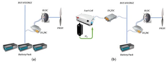
Figure 1.
Aircraft propulsion architecture: (a) the initial battery-based; (b) the proposed fuel cell-based.
A static DC/DC converter has been introduced mainly to step the stack voltage up to the BUS voltage set by the battery pack voltage. In Table 1, an estimation of the two propulsion systems’ weight is presented. As the table shows, the weight of both architectures is fairly comparable. All other components, such as the inverter, BLDC electric motor, and propeller are, obviously, the same in both architectures.

Table 1.
Propulsion system weight constraint analysis.
The H2 supply system weight has been estimated from the gravimetic index GI for hydrogen (gas-phase) aircraft fuel system. According to Equation (1) for these tipical systems [21,22,23]:
where is the total mass of the hydrogen and is the total mass of the system. Since a mass of 1 kg of hydrogen has been stored in the proposed system, the total H2 supply system weight has been estimated at 10 kg considering an additional safety factor.
4. Numerical Model
The numerical analysis has been developed in Simcenter Amesim (Siemens Digital Industries Software; Plano, TX, USA). This software package provides a suite for 0D-1D numerical simulations aimed at modeling and analyzing multi-domain systems to predict and optimize the performance of multi-disciplinary integrated models [24].
Figure 2 displays an overview of the developed numerical model for the fuel cell-based system. The battery-based model represents a portion of this numerical model.
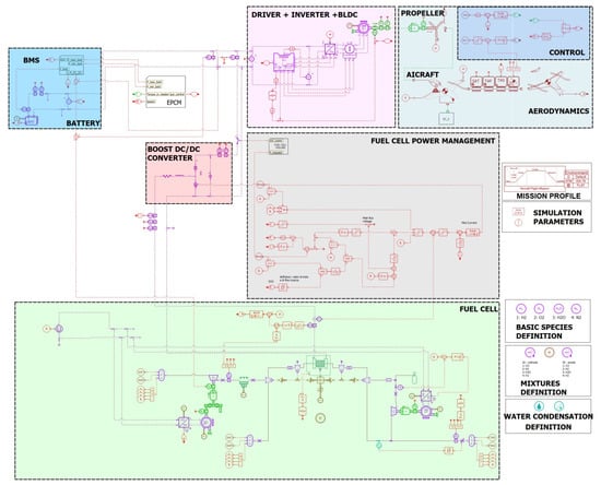
Figure 2.
Numerical model of the fuel cell-based architecture.
4.1. Battery Source
The battery pack architecture has been modeled using a high-energy nickel-cobalt-aluminum-graphite (NCA-C) li-ion cell with a capacity of 2.95 Ah. This cell is available in the pre-calibrated database of Simcenter Amesim and its thermal and electrical dynamic behaviors have already been validated by experimental tests conducted by the IFP Energies Nouvelles institute. The cell model considers diffusion phenomena (transient behavior). Concerning the dynamic voltage drops, the NCA-C cell model covers ohmic resistance and diffusion. These effects have been modeled by an equivalent electric circuit, which includes a voltage source, RC circuits for transient behavior and ohmic resistance. The equivalent circuit is presented in Figure 3.
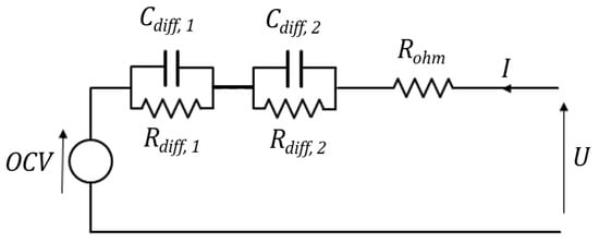
Figure 3.
The equivalent electrical circuit for battery cell modeling.
Two RC loops have been used for modeling the diffusion phenomena, which are extensively described in the Simcenter Amesim user’s guide [25]. The resistance and capacitance parameters are expressed as a function of the state of charge, temperature and input current; the ohmic resistance parameter has two different values for charging and discharging. The cell voltage is modeled according to Equations (2)–(4):
where
and
As mentioned in a previous section, the architecture of the battery pack for the battery-based propulsion system consists of 154 cells in series with 12 strings in parallel; on the other hand, for the proposed fuel cell-based system, the number of strings has been re-sized to 4, reducing the stored energy from a value of 20.17 kWh to 6.50 kWh. The cell has a standard charge rate of 0.5 C and a discharge rate of 3 C.
4.2. Fuel Cell Source
The PEM fuel cell has been modeled using the electrochemical dynamic model available in Simcenter Amesim [26]. Basically, the approach here considered includes:
- two electrodes, identified by catalyst layers where the two half-reactions occur;
- a membrane, where the water transport can occur;
- two GDLs, identified by porous media used to deliver the reactant species to the electrode;
- two bipolar plates, to simulate the inlet and outlet conditions at both anode and cathode sides.
The cell voltage according to Equation (5), is obtained by subtracting from the Nernst potential at both anode and cathode side the overvoltages at the cathode and at anode and the ohmic voltage drop due to membrane proton resistance [27].
The fuel cell electric equivalent schematic has been presented in Figure 4.
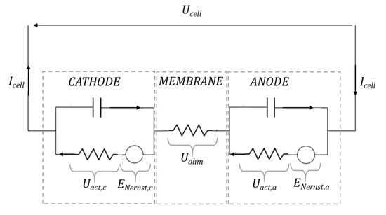
Figure 4.
The equivalent electrical circuit for fuel cell modeling.
4.3. Electrical BLDC Motor
The choice of the electric motor that will drive the propeller of an aircraft is of crucial importance in the whole propulsion system. The reference variables are the thrust of the propeller, the flight speed and the speed of rotation of the motor. Considerable attention must be paid to the motor-load coupling and to the identification of the power/torque characteristic with respect to the optimal speed for the reduction of energy consumption and noise. For aeronautical applications, and in particular, in a fully electric aircraft, the motor must have:
- high power density;
- high specific torque values;
- rotation speeds compatible with the propeller chosen to avoid heavy gearbox;
- diameters of the external case compatible with the nose of the aircraft;
- the possibility of working in overload for few minutes;
- high reliability.
The above-mentioned characteristics have led to the selection of a brushless permanent magnet motor [28,29] identified with the abbreviations PMSM or BLDCM 3-phase axial flux. An detailed view is presented in Figure 5.
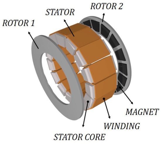
Figure 5.
An example of Axial flux permanent magnet synchronous machine, es. with a yokeless and segmented armature (YASA®).
The configuration of this motor exhibits disc-shaped cores and flat air gaps. The commercial electric motor chosen for this application is the EMRAX 268 motor [30], whose operating range of continuous power is from 67 to 107 kW and the instantaneous peak value is up to 200 kW at 4000 rev/min. The motor datasheet shows a quite large range of some data since multiple DC voltage levels are possible in combination with different cooling fluids. Typical values for the 2000 rev/min operation are shown in Table 2 below.
Table 2.
Parameters of the air-cooled EMRAX 268 motor at 2000 rev/min.
4.4. Propeller, Aerodynamics and Mission Profile
The mission profile is made up of five legs: take-off, climb, cruise, descent, and approach. The aircraft climbs to an altitude of 1000 m with a rate of climb of 2.7 m/s. On the climb and cruise leg, the aircraft velocity is kept constant and is partially reduced during the descent. As anticipated, the overall MTOW is the same for both architectures. Neglecting the weight of the hydrogen consumed, the length of each flight segment is the same except for the cruise section which can vary depending on the propulsion performance. The descent is considered to have started when the SoC of batteries is 20% for both architectures and FBPA (Fuel cell-Based Propulsion Architecture) when the hydrogen quantity is such that at landing is at least 10% of the initial value. On each mission leg, a given thrust is needed to overcome the aerodynamic drag which is computed using the drag coefficient defined in Equation (6):
where and are the drag and lift coefficients, is the drag coefficient at zero lift, is the aspect ratio, e is the Oswald efficiency factor (for a lightweight single-engine aircraft, the following assumptions were made: , , and is interpolated on aerodynamic lookup tables of an airfoil for general aviation aircraft). The drag force is given by Equation (7):
where V is the aircraft velocity, S is the wing area, is the air density and thrust is computed from Equation (8):
being W and the aircraft weight and the climb flight path angle, respectively. Thrust is provided by the propeller which is driven by the electric motor. Except for take-off where a constant maximum value has been generally assumed, shaft power is obtained as , where . Propeller has been modeled after McCormick [31] by means of typical propeller power curves as a function of the advance ratio (n is the propeller speed in rev/min and D is the propeller diameter) and blade angle and propeller efficiency. For the present case study, the propeller curves have been obtained by using an embedded module that allows scaling a reference propeller map with the actual design parameters (by setting J and , the corresponding values of and have been calculated). The present study simulates all the five mission phases for both battery-based and fuel cell-based architectures and the length of the cruise leg is the performance criterion for ranking the architectures under analysis. The results of the initial calculations are illustrated Figure 6.
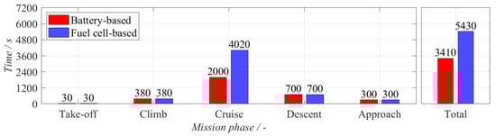
Figure 6.
Length of time of mission phases for both architecture.
The distance traveled in the cruise phase has been set based on the main constraint where the battery state of charge () has to be the same for both architectures at the initial () and final stage (). The hydrogen mass stored onboard with the designed architecture is 1 kg; the minimum quantity at landing has to be at least of the initial value. The mission profile applied to both propulsion architectures, in terms of required altitude and speed, is presented in the two upper plots of Figure 7.
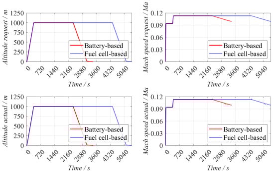
Figure 7.
Aircraft altitude and speed as a function of the time.
In the same figure, the aircraft’s actual altitude and speed is presented in the lower plots. It is visible how both architectures are able to fulfill the requests.
5. Results and Discussion
In this section, a comparison between results obtained by the two numerical models built respectively on the two analyzed architectures is presented. The simulations produced the expected results and the first data used to compare the two models is the distance traveled. The numerical model of the fuel cell-based architecture required around 2000 s on an Intel(R) Core(TM) i7-8665U CPU @ 1.90–2.11 GHz with 16.0 GB RAM to complite the entire simulation. Once the constraints have been declared, a parameter () has been set to evaluate the percentage of the range extension using the fuel cell-based architecture (), instead of using the battery-based architecture (). Its value can be easily calculated through Equation (9):
Results of both simulations have been presented in Table 3, where an important range extension has been achieved with the proposed system.
Table 3.
Range extension using a fuel cell-based architecture.
Figure 8 shows the power graphs for both architectures analyzed. The battery-based system graph shows how the battery pack supplies power to the motor shaft (which is greater when the efficiency of the inverter is considered).
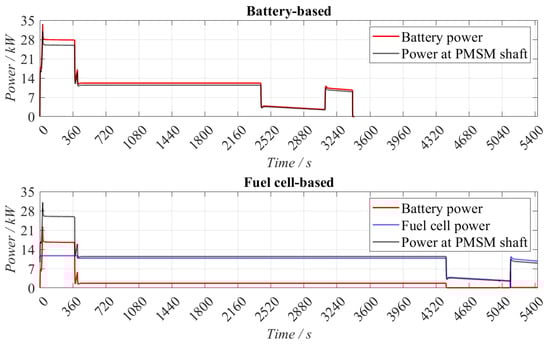
Figure 8.
Power provided by electrochemical sources and available at motor shaft for both architectures.
The second plot of Figure 8 is relative to the hybrid system based on a fuel cell architecture and analogously shows the power transferred from the sources to the system. The primary power is provided by the fuel cell, which is assisted by the small battery pack (6.5 Ah) during the high-power requests. In the cruise phase, the battery continues to work in synergy with the fuel cell, to reduce the hydrogen needed by the mission and utilize the onboard stored energy in the battery package, optimizing the energy management. Around 15% of the total requested power is provided by the battery source in the cruising phase. The introduction of a fuel cell electrochemical source impacts the power balance of the plant since it needs extra power to sustain the electrochemical reaction. For this reason, the power needed by the compressor at the cathode side to set the correct stoichiometric oxygen flux and the power by the hydrogen recirculation pump have been directly taken from the main bus.
Figure 9 shows subplots to compare the batteries SoC of the two architectures and the hydrogen mass-consumed during the mission profile. In particular, the graph on the top shows that the constraints have been respected. The graph on the bottom says that the final percentage value of the battery SoC is comparable between the two architectures and the molecular hydrogen consumption has been kept to less than 900 g (100 g of residual hydrogen).
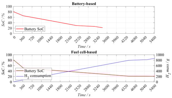
Figure 9.
Battery SoC and molecular hydrogen consumption for the two analyzed systems.
Figure 10 are presented to show a comparison of the energy, expressed in (MJ), used by both architectures for each mission phase. It is evident how the fuel cell-based system has more energy onboard, which can be used during the cruise phase. The other phases show a slightly increment of the energy needed, since the fuel cell voltage has been stepped up using a DC/DC converter that generates minimal losses.

Figure 10.
Energy used for each mission phases for both architectures.
In order to study the specific energy of the propulsion systems based on both architectures, a factor, expressed in (MJ/kg) and defined as the ratio between the total amount of energy used and the weight of the propulsion system, has been introduced. The results from its calculations are presented in Table 4: the amount of energy stored onboard using the proposed fuel cell-based system increases significantly showing an increment of 66.7%.
Table 4.
Comparison of the propulsion system energy density.
6. Integration of an Ultracapacitor Module
Ultracapacitors (UCAP), also called electrochemical double-layer capacitors (EDLC), are electrostatic energy storage systems that can be used in association with battery systems to absorb or supply high electric power requests (or pulses). They prevent battery cells from premature aging due to high current, and high thermal losses generated inside the cells and packs. Ultracapacitors systems electrostatically store energy in the electrochemical double layer at electrodes/electrolyte interfaces enabling very fast energy conversion, thus providing the high capability of current absorption and release.
For this reason, an ultracapacitor pack has been introduced and analyzed in the fuel cell-based architecture to reduce the current supplied by the battery pack, during high-power request phases, like take-off, preventing the battery cells from excessive overheating and premature aging. This proposed architecture has been presented in Figure 11. The ultracapacitor module designed for this application (6 cells in series pack architecture) has a rated capacitance of 569 F, with a maximum current delivery of 1900 A. The cell selected is a 3500 F cylindrical cell with a maximum voltage of 2.7 V, corresponding to a module with a voltage of 16.2 V. The UCAP voltage has been stepped up through a DC/DC converter.

Figure 11.
Proposed fuel cell-based architecture with UCAP electrochemical source.
Ultracapacitor Source Numerical Modelling
As it has been done for the modeling of the battery electrochemical source, a similar approach has been done for the ultracapacitor numerical modeling, where an already validated dynamic cell model has been properly selected from the pre-calibrated database. This numerical model has been based on the study done in [32,33], it describes the electrical and thermal dynamic behavior of the UCAP cell using an equivalent electrical circuit schematic. This methodology takes into account phenomena regarding different scales of time, from high-frequency accumulation to extremely slow electrical leakage. The equivalent electrical circuit used for this study has been presented in Figure 12.
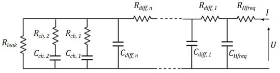
Figure 12.
The equivalent electrical circuit for ultracapacitor cell modeling.
In this figure, four different RC sub-circuits can be identified, each of them belonging to a different time scale (that is, time < 10 ms, time < 100 s, time < 3600 s, time > 3600 s). The resistance and capacitance parameters included in the sketch of Figure 12 have been estimated to match the impedance spectrum and galvanostatic measurements. Since the component modeling is not the purpose of this article, the model description and the equation used can be found in the Simcenter Amesim user’s guide [25].
In Table 5 an estimation of the weight breakdown of the system presented in Figure 12 has been done by considering components already available on the market. The integration of the UCAP sub-system increases the propulsion system weight by 23 kg, which represents a weight increment of 5%, a value still compatible with the aeronautical sector if it brings with it benefits in terms of safety and increase of components life.
Table 5.
Propulsion system weight constraint analysis.
An overview of the numerical model is presented in Figure 13, where it can be noticed a simplified model for the DC/DC converter, associated with the UCAP. Indeed, a functional block has been utilized to control the power supplied by the electrochemical source.
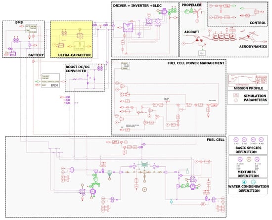
Figure 13.
Numerical model of the fuel cell-based architecture with UCAP module.
The power management strategy is presented in Figure 14; since one of the purposes of the article is to develop a numerical model which is able to let all the electrochemical sources work in synergy and demonstrate the effective range extension using a PEM fuel cell, a simple, robust and fast rule-based strategy has been adopted in this project phase, while more complex power management strategies [34] will be subsequently investigated. This strategy relies on a simple if-then rule, based on the power request; four levels of power have been defined a priori. The levels of power identify three different working configurations visible in the same figure. The role of the ultracapacitor module has already been clarified early in this section.
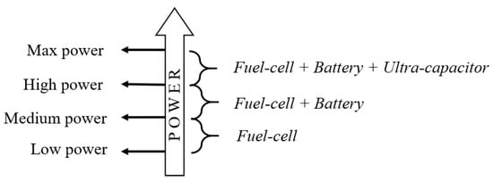
Figure 14.
Power management strategy.
The power contribution can be seen by the simulation results presented in Figure 15, where power supplied by the three electrochemical sources and the power at the motor shaft have been plotted for the same mission profile, presented in a previous section. A break in the x-axis (time) has been used to expand the temporal zone where the detachment from the ground occurs. In this transition, it is visible how the UCAP works, protecting the battery from higher power requests, supplying the overcurrent during the spike of power.
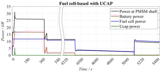
Figure 15.
Power provided by electrochemical sources and available at motor shaft for the architecture with UCAP module.
The battery pack protection is even more visible if it is analyzed in terms of C-Rate; indeed, from Figure 16, where a C-Rate comparison between the system with and without the UCAP in shown; it is notable how the ultracapacitor protects the battery from power spikes, keeping the battery C-Rate below an absolute value of 3 (the maximum discharging rate for the used cell is 5). While reducing the higher current request, the battery pack life can be increased according to [35,36].
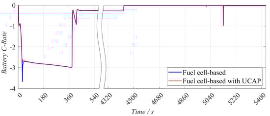
Figure 16.
Battery discharging rate comparison.
Finally, in Figure 17 the state of charge for both battery pack and ultracapacitor module during the mission profile is shown. The energy management has been still designed to keep the final battery state of charge around a value of 20%, confirming that the 5% of extra weight added onboard does not affect in a marked way the energy required to complete the same mission. Around 25% of UCAP SoC has been used to protect the battery from the higher current request during the take-off, allowing potentially multiple uses without re-charging.

Figure 17.
Battery and ultracapacitor state of charge during the requested mission profile.
7. Conclusions
Numerical models are very powerful tools in the analysis of fully electric propulsion systems involving several electrochemical sources. The correct representation of the operating status of the system’s individual components within a comprehensive model is fundamental if all the dynamic aspects and mutual interactions must be considered simultaneously. Furthermore, the models presented here are designed to evolve toward the digital twin of real propulsion system demonstrators. This will help reduce the number of tests and avoid critical or severe test conditions. This article presents three models including all of the components, from energy sources to propeller, taking advantage of the model libraries available in Simcenter Amesim. They also integrate aircraft dynamics and a mission profile in terms of altitude and speed. The models were applied to simulate the performance of propulsion systems based on a given energy source (battery, fuel cell, ultracapacitor, or a combination thereof) under the constraint of an unaltered mass of the propulsion system. In particular, the first section of the article has proposed a comparison between a battery-based and a fuel cell-based architecture. The first architecture is composed of one electrochemical source, the battery pack, including 154 lithium-ion cells in series and 12 strings in parallel for a capacity of 35.4 Ah. The second architecture is composed of two electrochemical sources, a fuel cell that is capable to supply a maximum power of 11.7 kW and a battery pack with a capacity of 11.4 Ah (only 4 strings of 154 cells in series). Both systems have been designed to provide at least 30 kW of power at the motor shaft. Being the models parameterized, several simulations have been launched from which it emerges that also small aircraft like a motor glider could take advantage of hydrogen-powered architectures. It has been shown that the propulsion system which integrates the fuel cell that works in synergy with a smaller battery pack brings higher energy density onboard the aircraft (+66.7%) which results in a significant range extension (+61%). In addition the architecture accommodating an ultracapacitor module into the fuel cell-based system has shown that, if opportunely used, the UCAP is capable to protect the battery from higher power requests (spikes), reducing electrical and thermal stresses resulting in a life extension of the battery pack. Ultimately the applications have shown that the models are robust and that they can be successfully launched on low-demand computing platforms with an acceptable runtime. The next phases of the project will be devoted to improving the models presented here to incorporate thermal aspects and more sophisticated energy management strategies even if the model complexity, already significant, is expected to increase.
Author Contributions
Conceptualization, G.M., G.D.L. and A.P.; Data curation, G.M.; Formal analysis, G.M.; Investigation, G.M.; Methodology, G.M.; Project administration, A.P.; Software, G.M.; Supervision, A.P.; Validation, G.M.; Writing—original draft, G.M., G.D.L. and A.P.; Writing—review & editing, G.M., G.D.L. and A.P. All authors have read and agreed to the published version of the manuscript.
Funding
This research was funded by CIRA grant number 21-COM-0059 in the framework of PRORA, the national (Italian) aerospace research programme, of which the Electroplane project is part.
Institutional Review Board Statement
Not applicable.
Informed Consent Statement
Not applicable.
Data Availability Statement
Not applicable.
Acknowledgments
The authors thank all the Electroplane team whose participants have provided (and continue to provide) valuable and constructive suggestions for the development of this research work.
Conflicts of Interest
The authors declare no conflict of interest.
Abbreviations
The following abbreviations are used in this manuscript:
| AC | Alternate Current |
| BLDC or BLDCM | Brushless DC |
| BoP | Balance of Plant |
| CPU | Central Processing Unit |
| DC | Direct Current |
| EDLC | Electrochemical double-layer capacitor |
| GLDs | Gas Diffusion Layers |
| HV | High Voltage |
| LV | Low Voltage |
| MEA | More Electric Aircraft |
| MMF | Magnetomotive Force |
| MTOW | Max Take-Off Weight |
| MV | Medium Voltage |
| NCA-C | Nickel-Cobalt-Aluminum Grafite |
| OCV | Open Circuit Voltage |
| PEM | Proton Exchange Membrane |
| PMSM | Permanent Magnet Synchronous Motor |
| RAM | Random Access Memory |
| RC | Resistor-Capacitor |
| SoC | State of Charge |
| UAV | Unmanned Aerial Vehicle |
| UCAP | Ultracapacitor |
References
- FlightGlobal. Available online: https://www.flightglobal.com/engines/wideroe-and-rolls-royce-pursue-all-electric-aircraft-based-on-tecnam-design/142845.article (accessed on 16 May 2022).
- Geekwire. Available online: https://www.geekwire.com/2022/eviation-makes-a-deal-to-sell-cape-air-2675-electric-airplanes-first-flight-test-now-set-for-summer/ (accessed on 16 May 2022).
- Trainelli, L.; Salucci, F.; Comincini, D.; Riboldi, C.E.D.; Rolando, A. Sizing and performance of hydrogen-driven airplanes. In Proceedings of the Italian Association of Aeronautics and Astronautics (AIDAA), Rome, Italy, 9–12 September 2019. [Google Scholar]
- International Energy Agency. Available online: https://www.iea.org/reports/aviation (accessed on 20 December 2021).
- European Commission, Directorate-General for Mobility and Transport, Directorate-General for Research and Innovation, Flightpath 2050 : Europe’s Vision for Aviation: Maintaining Global Leadership and Serving Society’s Needs; Publications Office: Luxembourg, 2012.
- Zaporozhets, O.; Isaienko, V.; Synylo, K. PARE preliminary analysis of ACARE FlightPath 2050 environmental impact goals. Ceas Aeronaut. J. 2021, 12, 653–667. [Google Scholar] [CrossRef] [PubMed]
- Lapeña-Rey, N.; Mosquera, J.; Bataller, E.; Ortí, F. The Boeing Fuel Cell Demonstrator Airplane; SAE Technical Paper Series; SAE International: Warrendale, PA, USA, 2007. [Google Scholar]
- Renouard-Vallet, G.; Kallo, J.; Saballus, M.; Gores, F.; Schmithals, G.; Friedrich, K. Fuel Cell Systems for a Greener Aviation. In Proceedings of the 3rd International Symposium on Energy Engineering, Economics and Policy: EEEP 2011, Orlando, FL, USA, 9–14 July 2011. [Google Scholar]
- Romeo, G.; Borello, F.; Correa, G.; Cestino, E. When Fuel Cells Fly. Fuel cell systems for a greener aviation. In Aerospace Engineering; SAE International: Warrendale, PA, USA, 2012; pp. 26–29. [Google Scholar]
- Romeo, G.; Cestino, E.; Borello, F. More/All Electric Aircraft Based on Fuel Cell Energy System: The ENFICA-FC Experience. In Proceedings of the 28th International Conference of the Aeronautical Sciences (ICAS 2012), Brisbane, Australia, 23–28 September 2012. [Google Scholar]
- Romeo, G.; Borello, F.; Cestino, E. Design of inter-city transport aircraft powered by fuel cell & flight test of zero emission 2-seater aircraft powered by fuel cells. In Proceedings of the 2012 Electrical Systems for Aircraft, Railway and Ship Propulsion, Bologna, Italy, 16–18 October 2012. [Google Scholar]
- Müller, C.; Kieckhäfer, K.; Spengler, T. The influence of emission thresholds and retrofit options on airline fleet planning: An optimization approach. Energy Policy 2018, 112, 242–257. [Google Scholar] [CrossRef]
- Di Lorenzo, G.; Frosina, E.; De Petrillo, L.; Lauria, D.; Senatore, A.; Curreri, F.; Saccone, G.; Kivel Mazuy, M.; Pascarella, C. Design and Development of Hybrid-Electric Propulsion Model for Aeronautics. MATEC Web Conf. 2019, 304, 03012. [Google Scholar] [CrossRef][Green Version]
- Frosina, E.; Caputo, C.; Marinaro, G.; Senatore, A.; Pascarella, C.; Di Lorenzo, G. Modelling of a Hybrid-Electric Light Aircraft. Energy Procedia 2017, 126, 1155–1162. [Google Scholar] [CrossRef]
- Frosina, E.; Senatore, A.; Palumbo, L.; Di Lorenzo, G.; Pascarella, C. Development of a Lumped Parameter Model for an Aeronautic Hybrid Electric Propulsion System. Aerospace 2018, 5, 105. [Google Scholar] [CrossRef]
- Jarry, T.; Lacressonnière, F.; Jaafar, A.; Turpin, C.; Scohy, M. Modeling and Sizing of a Fuel Cell—Lithium-Ion Battery Direct Hybridization System for Aeronautical Application. Energies 2021, 14, 7655. [Google Scholar] [CrossRef]
- Radmanesh, H.; Heidari Yazdi, S.; Gharehpetian, G.; Fathi, S. Modelling and Simulation of Fuel Cell Dynamics for Electrical Energy Usage of Hercules Airplanes. Sci. World J. 2014, 2014, 593121. [Google Scholar] [CrossRef] [PubMed]
- Miazga, T.; Iwański, G.; Nikoniuk, M. Energy Conversion System and Control of Fuel-Cell and Battery-Based Hybrid Drive for Light Aircraft. Energies 2021, 14, 1073. [Google Scholar] [CrossRef]
- Nya, B.; Brombach, J.; Schulz, D. Benefits of higher voltage levels in aircraft electrical power systems. In Proceedings of the 2012 Electrical Systems for Aircraft, Railway and Ship Propulsion, Bologna, Italy, 16–18 October 2012. [Google Scholar]
- MIL STD 704E; Department of Defense Interface Standard: Aircraft Electric Power Characteristics. U.S. Department of Defense: Washington, DC, USA, 2004.
- Gong, A.; Verstraete, D. Fuel cell propulsion in small fixed-wing unmanned aerial vehicles: Current status and research needs. Int. J. Hydrogen Energy 2017, 42, 21311–21333. [Google Scholar] [CrossRef]
- Zuttel, A. Materials for hydrogen storage. Mater. Today 2003, 6, 24–33. [Google Scholar] [CrossRef]
- Tzimas, E.; Filiou, C.; Peteves, S.; Veyret, J. Hydrogen Storage: State-of-the-Art and Future Perspective; EUR 20995 EN. cat. No. LD-NA-20995-EN-C; 2003. JRC26493; European Commission: Brussels, Belgium, 2003. [Google Scholar]
- Siemens PLM Software. Simcenter Amesim Help; User’s Guide; Siemens PLM Software: Plano, TX, USA, 2021. [Google Scholar]
- Siemens PLM Software. Simcenter Amesim: Electric Storage Library; User’s Guide; Siemens PLM Software: Plano, TX, USA, 2021. [Google Scholar]
- Siemens PLM Software. Simcenter Amesim: Fuel Cell Library; User’s Guide; Siemens PLM Software: Plano, TX, USA, 2021. [Google Scholar]
- Larminie, J.; Dicks, A. Fuel Cell Systems Explained, 2nd ed.; Wiley: New York, NY, USA, 2013. [Google Scholar]
- Momen, F.; Rahman, K.; Son, Y. Electrical Propulsion System Design of Chevrolet Bolt Battery Electric Vehicle. IEEE Trans. Ind. Appl. 2019, 55, 376–384. [Google Scholar] [CrossRef]
- Mersha, T.; Du, C. Co-Simulation and Modeling of PMSM Based on Ansys Software and Simulink for EVs. World Electr. Veh. J. 2021, 13, 4. [Google Scholar] [CrossRef]
- Emrax. Available online: https://emrax.com/e-motors/emrax-268/ (accessed on 19 November 2021).
- Mccormick, B.; Aljabri, A.; Jumper, S.; Martinovic, Z. The Analysis of Propellers Including Interaction Effects; SAE Technical Paper Series; SAE International: Warrendale, PA, USA, 1979. [Google Scholar]
- Rafik, F.; Gualous, H.; Gallay, R.; Crausaz, A.; Berthon, A. Frequency, thermal and voltage supercapacitor characterization and modeling. J. Power Sources 2007, 165, 928–934. [Google Scholar] [CrossRef]
- Prada, E.; Bernard, J.; Mingant, R.; Sauvant-Moynot, V. A physical approach to Electrochemical Storage System multi-scale modeling: Electrochemical Double Layer Capacitors (as case studies). In Proceedings of the 25th World Battery, Hybrid and Fuel Cell Electric Vehicle Symposium and Exhibition (EVS25), Shenzhen, China, 5–9 November 2010. [Google Scholar]
- Boukoberine, M.; Donateo, T.; Benbouzid, M. Optimized Energy Management Strategy for Hybrid Fuel Cell Powered Drones in Persistent Missions using Real Flight Test Data. IEEE Trans. Energy Convers. 2022. [Google Scholar] [CrossRef]
- Wikner, E.; Thiringer, T. Extending Battery Lifetime by Avoiding High SOC. Appl. Sci. 2018, 8, 1825. [Google Scholar] [CrossRef]
- Wu, Z.; Zhu, G.; Wang, Q.; Yang, S.; Wang, J.; Kang, J. Study on Adaptive Cycle Life Extension Method of Li-Ion Battery Based on Differential Thermal Voltammetry Parameter Decoupling. Energies 2021, 14, 6239. [Google Scholar] [CrossRef]
Publisher’s Note: MDPI stays neutral with regard to jurisdictional claims in published maps and institutional affiliations. |
© 2022 by the authors. Licensee MDPI, Basel, Switzerland. This article is an open access article distributed under the terms and conditions of the Creative Commons Attribution (CC BY) license (https://creativecommons.org/licenses/by/4.0/).