
Experimental Study on the Effect of Rubbing Mode on Radial Crack Initiation in Labyrinth Seal Fins of Shrouded Turbine Blade

Abstract
:1. Introduction
2. Test System and Method
2.1. Test System
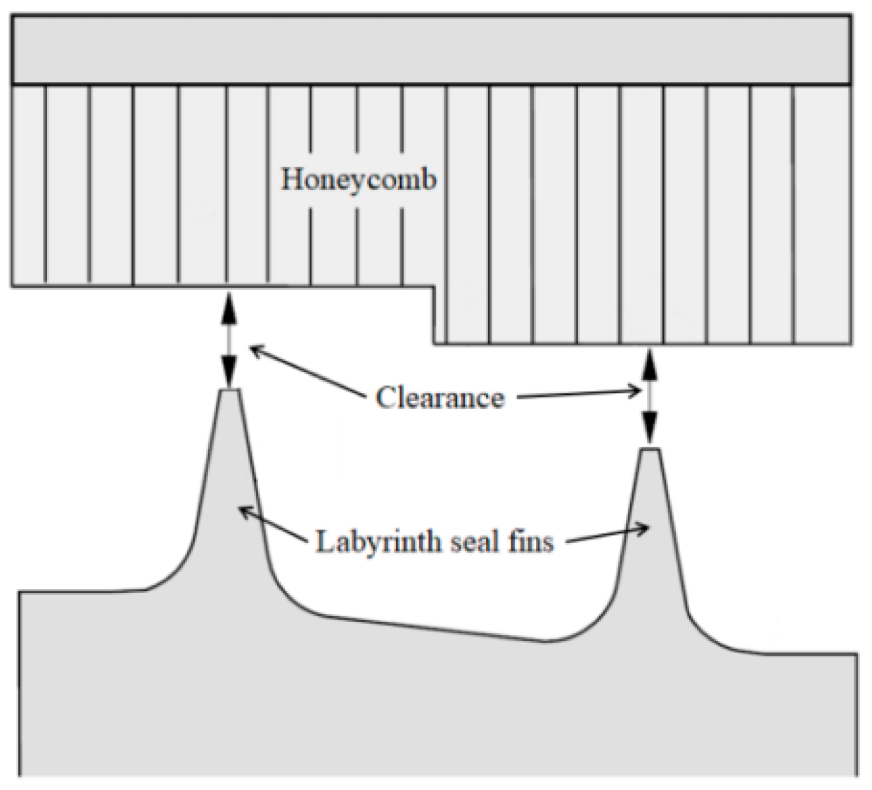
2.2. Test Sample
2.3. Test Process
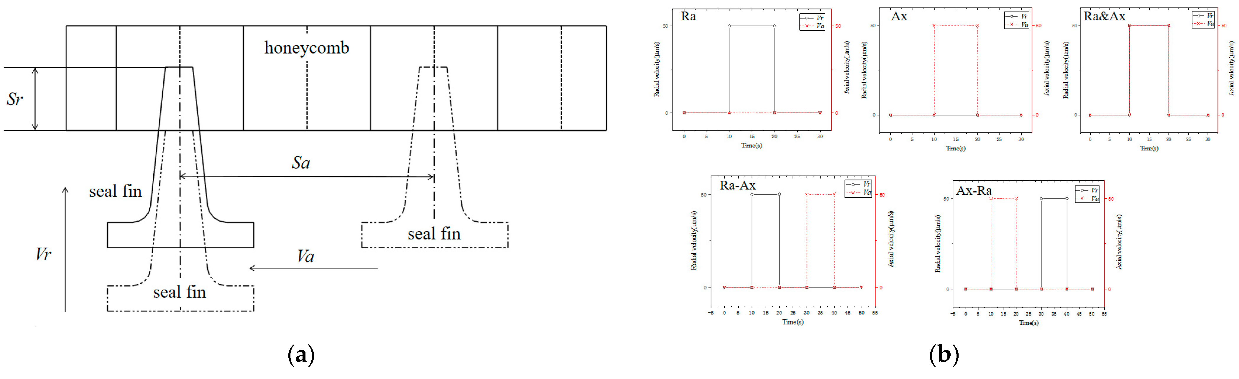
2.4. Test Parameters
3. Test Results
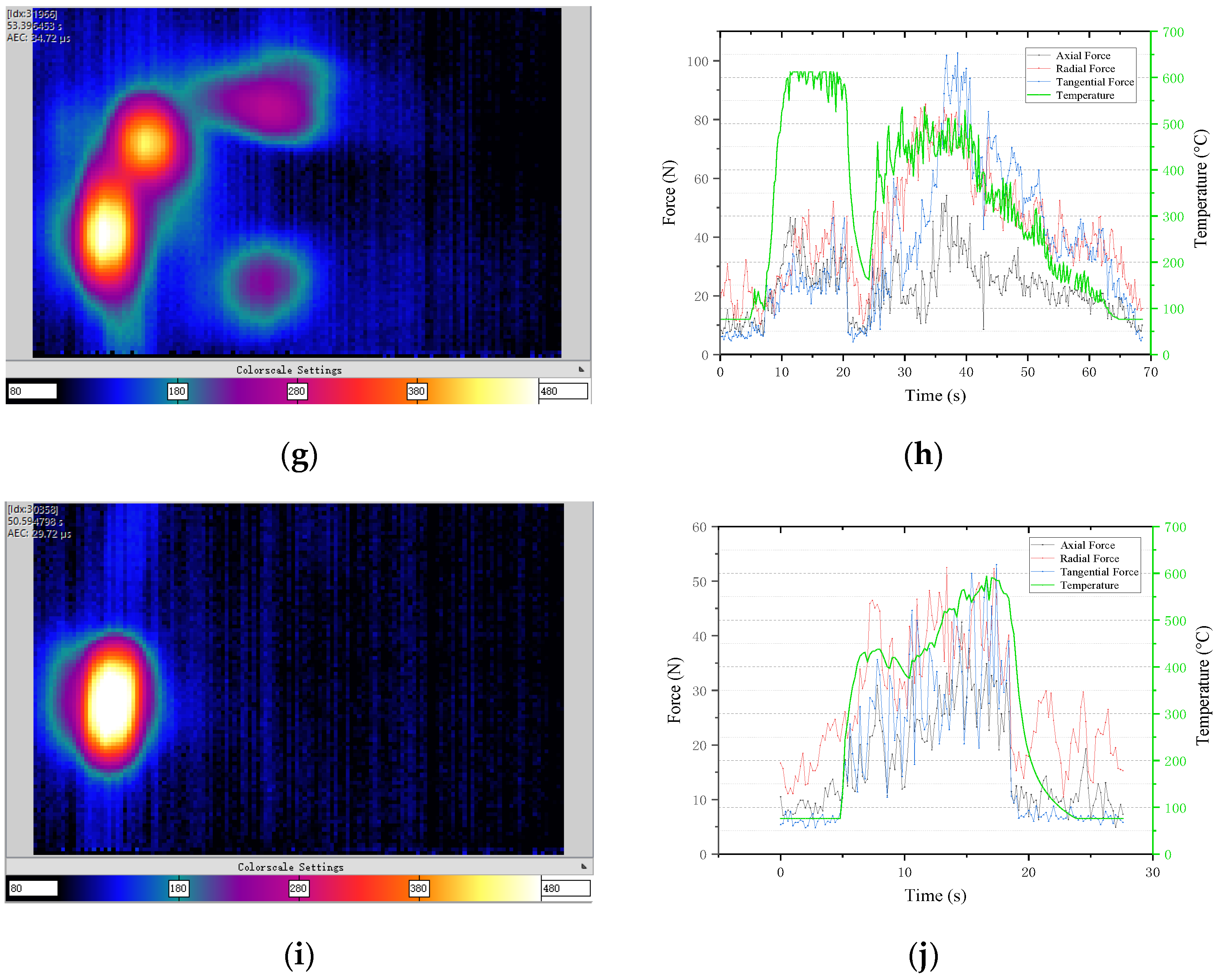
3.1. Effect of Rubbing Mode on Rubbing Temperature and Rubbing Force
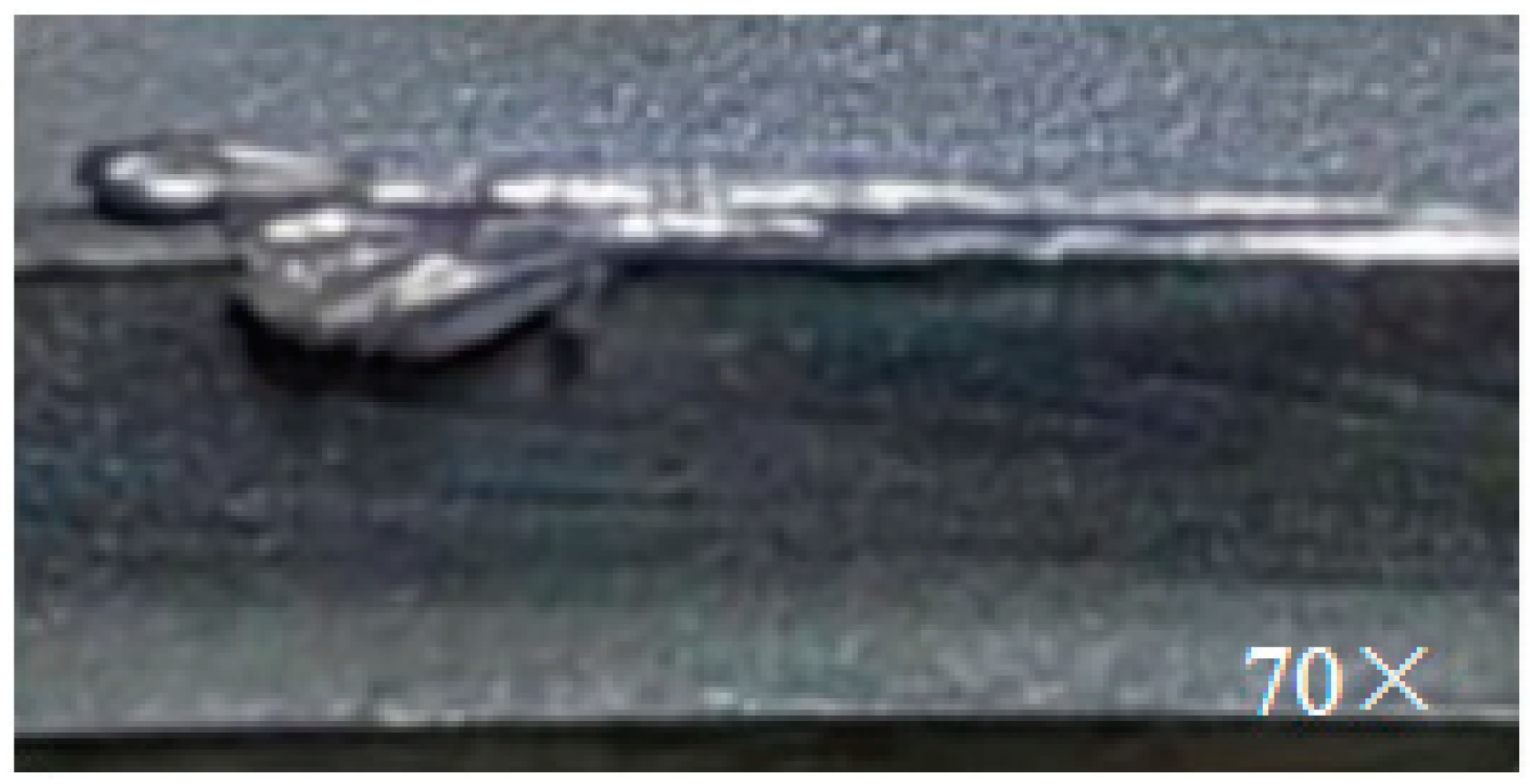
3.2. Effect of Rubbing Mode on Wear Morphology
3.3. Effect of Rubbing Mode on Crack Initiation
4. Conclusions of Testing
- (1)
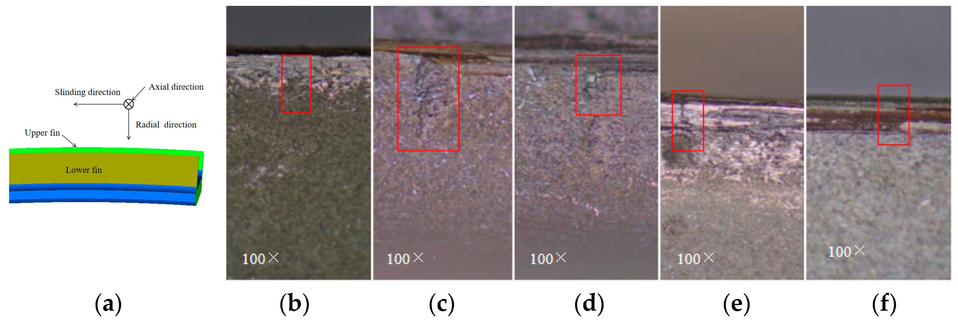
- Radial cracks will be formed on the fin tip and side of the fins under five rubbing modes, and the cracks are formed at the junction of the fin tip and side. The cracks on the fin tip surface of the fins extend in the axial direction, and the crack shape is mostly straight and parallel to each other. The cracks on the side extend in the radial direction, and the cracks are in the shape of crack-like.
- (2)
- Under the five rubbing modes, the value of radial force is significantly greater than that of axial force. The effect of tangential force on temperature is not obvious. When the tangential force increases rapidly, the rubbing temperature does not increase significantly. The temperature is mainly affected by radial force. The rubbing temperature increases with the increase of radial force and decreases with the decrease of radial force.
- (3)
- The maximum rubbing temperatures of radial rubbing and axial rubbing are equal, which is 611.95 °C. When the two successive rubbing modes are different, temperature of the latter can be lower than that of the corresponding individual rubbing model. The maximum temperature of axial rubbing in Ra-Ax is 529.89 °C, and the maximum temperature of radial rubbing in Ax-Ra is 528.82 °C. The simultaneous radial and axial rubbing and grinding will inhibit each other, and the rubbing temperature is 593.87 °C.
- (4)
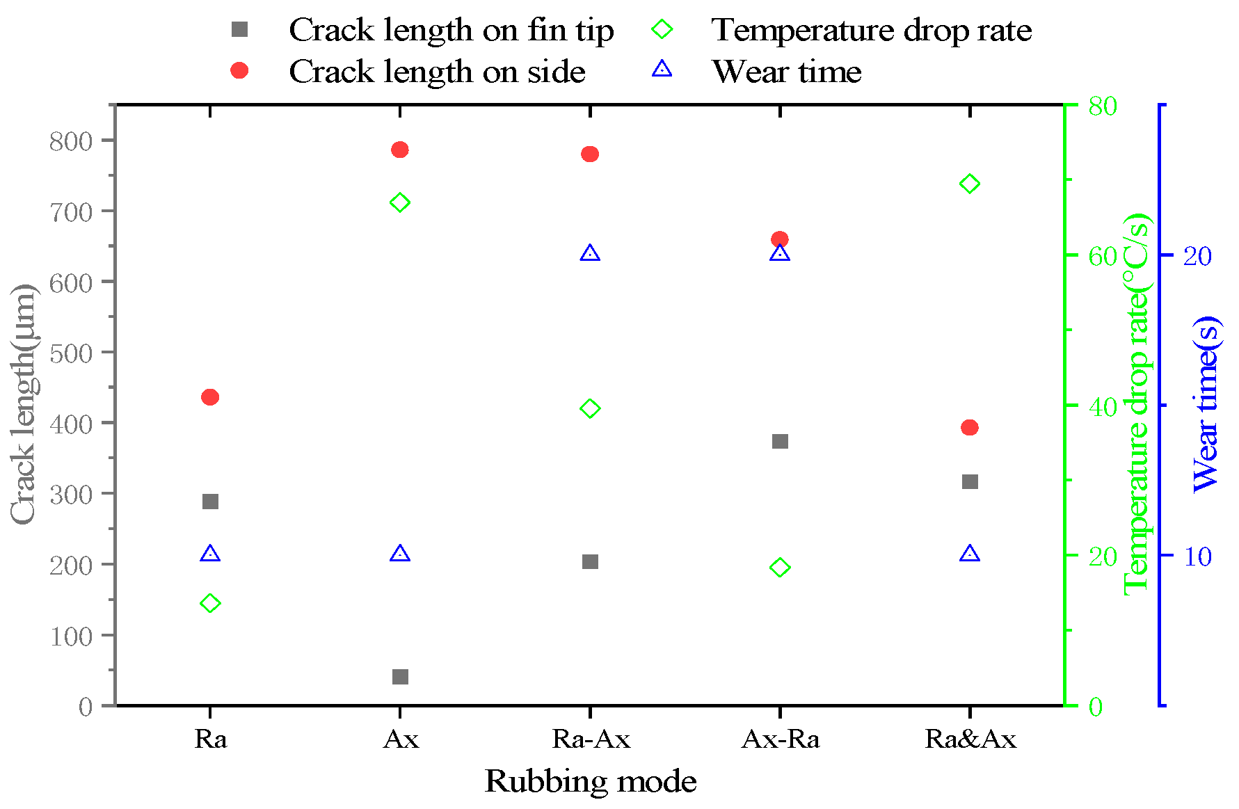
- There are obvious circumferential scratches on the fin tip surface of the fin scraped radially, and the fin tip surface of the fin rubbed axially is relatively smooth. Radial rubbing mainly affects the initiation of fin tip cracks, and axial rubbing mainly affects the initiation of side cracks. The crack in fin tip is mainly affected by the decreasing rate of rubbing temperature.
Author Contributions
Funding
Data Availability Statement
Conflicts of Interest
References
- DeMasi-Marcin, J.T.; Gupta, D.K. Protective coatings in the gas turbine engine. Surf. Coat. Technol. 1994, 68–69, 1–9. [Google Scholar] [CrossRef]
- Chupp, R.E.; Hendricks, R.C.; Lattime, S.B.; Steinetz, B.M. Sealing in Turbomachinery. J. Propuls. Power 2006, 22, 313–349. [Google Scholar] [CrossRef]
- Draskovich, B.S.; Frani, N.E.; Joseph, S.S.; Narasimhan, D. Abrasive Tip/Abradable Shroud System and Method For gas Turbine Compressor Clearance Control. U.S. Patent 5,704,759, 6 January 1998. [Google Scholar]
- Aslan-zada, F.E.; Mammadov, V.A.; Dohnal, F. Brush seals and labyrinth seals in gas turbine applications. Proc. Inst. Mech. Eng. Part A J. Power Energy 2013, 227, 216–230. [Google Scholar] [CrossRef]
- Dai, X.; Yan, X. Effects of Labyrinth Fin Wear on Aerodynamic Performance of Turbine Stages: Part II—Mushrooming Damages. In Proceedings of the ASME Turbo Expo 2019: Turbomachinery Technical Conference and Exposition, Phoenix, AZ, USA, 17–21 June 2019. [Google Scholar]
- Delebarre, C.; Wagner, V.; Paris, J.Y.; Dessein, G.; Denape, J.; Gurt-Santanach, J. An experimental study of the high speed interaction between a labyrinth seal and an abradable coating in a turbo-engine application. Wear 2014, 316, 109–118. [Google Scholar] [CrossRef]
- Pychynski, T.; Höfler, C.; Bauer, H.-J. Experimental Study on the Friction Contact between a Labyrinth Seal Fin and a Honeycomb Stator. J. Eng. Gas Turbines Power 2015, 138, 062501. [Google Scholar] [CrossRef]
- Zhang, N.; Xuan, H.-J.; Guo, X.-J.; Guan, C.-P.; Hong, W.-R. Investigation of high-speed rubbing behavior of labyrinth-honeycomb seal for turbine engine application. J. Zhejiang Univ.-Sci. A 2016, 17, 947–960. [Google Scholar] [CrossRef]
- Rathmann, U.; Olmes, S.; Simeon, A. Sealing Technology: Rub Test Rig for Abrasive/Abradable Systems. In Proceedings of the ASME Turbo Expo 2007: Power for Land, Sea, and Air, Montreal, QC, Canada, 14–17 May 2007; pp. 223–228. [Google Scholar]
- Delebarre, C.; Wagner, V.; Paris, J.Y.; Dessein, G.; Denape, J.; Gurt-Santanach, J. Tribological characterization of a labyrinth-abradable interaction in a turbo engine application. Wear 2017, 370–371, 29–38. [Google Scholar] [CrossRef]
- Thévenot, M.; Wagner, V.; Paris, J.Y.; Dessein, G.; Denape, J.; Harzallah, M.; Brunet, A.; Chantrait, T. Thermomechanical phenomena and wear flow mechanisms during high speed contact of abradable materials. Wear 2019, 426–427, 1102–1109. [Google Scholar] [CrossRef]
- Soler, D.; Saez De Buruaga, M.; Arrazola, P.J. Experimental investigation of contact forces and temperatures in rubbing interactions of honeycomb interstate seals. IOP Conf. Ser. Mater. Sci. Eng. 2021, 1193, 012070. [Google Scholar] [CrossRef]
- Ma, H.; Yin, F.; Guo, Y.; Tai, X.; Wen, B. A review on dynamic characteristics of blade–casing rubbing. Nonlinear Dyn. 2016, 84, 437–472. [Google Scholar] [CrossRef]
- Bogdanovich, P.N.; Tkachuk, D.V. Thermal and thermomechanical phenomena in sliding contact. J. Frict. Wear 2009, 30, 153–163. [Google Scholar] [CrossRef]
- Kennedy, F.E. Thermal and thermomechanical effects in dry sliding. Wear 1984, 100, 453–476. [Google Scholar] [CrossRef]
- Kennedy, F.E.; Karpe, S.A. Thermocracking of a mechanical face seal. Wear 1982, 79, 21–36. [Google Scholar] [CrossRef]
- Rossmann, A. Die Sicherheit von Turbo-Flugtriebwerken, Band 2; Turbo Consult: Karlsfeld, Germany, 2000. [Google Scholar]
- Kim, S.-W.; Segu, D.Z.; Kim, S.-S. The Thermo-mechanical Cracking Analysis of Break System. Procedia Eng. 2013, 68, 586–592. [Google Scholar] [CrossRef]
- Pychynski, T.; Dullenkopf, K.; Bauer, H.-J. Theoretical Study on the Origin of Radial Cracks in Labyrinth Seal Fins due to Rubbing. In Proceedings of the ASME Turbo Expo 2013: Turbine Technical Conference and Exposition, San Antonio, TX, USA, 3–7 June 2013. [Google Scholar]
- Hühn, L.; Rieger, F.C.; Bleier, F.; Schwitzke, C.; Bauer, H.-J.; Behnisch, T. Extensive Investigations on Radial Crack Formation in Labyrinth Seals of Aircraft Engines. In Proceedings of the Deutscher Luft- und Raumfahrtkongress, Friedrichshafen, Germany, 4–6 September 2018; p. 8 S. [Google Scholar]
- Lu, B.; Ma, X.; Wu, C.; Xuan, H.; Hong, W. The Wear of Seal Fins during High-Speed Rub between Labyrinth Seal Fins and Honeycomb Stators at Different Incursion Rates. Materials 2021, 14, 979. [Google Scholar] [CrossRef] [PubMed]
- Lu, B.; Xuan, H.; Ma, X.; Han, F.; Hong, W.; Zhi, S. The Influence of the Axial Rub Added in the Radial Rub on the Wear of the Seal Fins during the High Speed Rub of Labyrinth-Honeycomb Seal. Materials 2021, 14, 1997. [Google Scholar] [CrossRef] [PubMed]


| Composition | C | Cr | Ni | Co | W | Mo | Al | Ti | Fe |
|---|---|---|---|---|---|---|---|---|---|
| Content/% | 0.16 | 13.8 | balance | 9 | 4.0 | 3.8 | 3.1 | 4.8 | 0.32 |
| Composition | Ni | Cr | Fe | Mo | Co | W | C | Mn | Si | B |
|---|---|---|---|---|---|---|---|---|---|---|
| Content/% | balance | 22 | 18 | 9 | 1.5 | 0.6 | 0.1 | 0.98 | 0.95 | 0.007 |
| Rene’80 | Hastelloy X | |||||||
|---|---|---|---|---|---|---|---|---|
| E/GPa | α/10−6·°C−1 | σb/MPa | σp0.2/MPa | E/GPa | α/10−6·°C−1 | σb/MPa | σp0.2/MPa | T/°C |
| 199.0 | 12.56 | 1090 | 815 | 187.6 | 12.5 | 809 | 361 | 200 |
| 175.2 | 17.16 | 985 | 630 | 160.3 | 14.8 | 531 | 227 | 600 |
| 171.0 | 18.7 | 975 | 660 | 156.6 | 15.2 | 496 | 225 | 650 |
| 168.8 | 18.42 | 1000 | 610 | 154.0 | 15.5 | 446 | 223 | 700 |
| Rubbing Mode | Sr (mm) | Vr (μm/s) | Sa (mm) | Va (μm/s) | Number of Blades |
|---|---|---|---|---|---|
| Ra | 0.5 | 50 | - | - | 5 |
| Ai | - | - | 0.5 | 50 | 4 |
| Ra-Ai | 0.5 | 50 | 0.5 | 50 | 5 |
| Ai-Ra | 0.5 | 50 | 0.5 | 50 | 3 |
| Ra&Ai | 0.5 | 50 | 0.5 | 50 | 2 |
Publisher’s Note: MDPI stays neutral with regard to jurisdictional claims in published maps and institutional affiliations. |
© 2022 by the authors. Licensee MDPI, Basel, Switzerland. This article is an open access article distributed under the terms and conditions of the Creative Commons Attribution (CC BY) license (https://creativecommons.org/licenses/by/4.0/).
Share and Cite
Yang, Y.; Mi, Z.; Zhang, W.; Chang, J.; Liu, Y.; Zhong, B.; Yang, W. Experimental Study on the Effect of Rubbing Mode on Radial Crack Initiation in Labyrinth Seal Fins of Shrouded Turbine Blade. Aerospace 2022, 9, 441. https://doi.org/10.3390/aerospace9080441
Yang Y, Mi Z, Zhang W, Chang J, Liu Y, Zhong B, Yang W. Experimental Study on the Effect of Rubbing Mode on Radial Crack Initiation in Labyrinth Seal Fins of Shrouded Turbine Blade. Aerospace. 2022; 9(8):441. https://doi.org/10.3390/aerospace9080441
Chicago/Turabian StyleYang, Yicheng, Zhaoguo Mi, Wencan Zhang, Jiaqi Chang, Yongjun Liu, Bintao Zhong, and Weihua Yang. 2022. "Experimental Study on the Effect of Rubbing Mode on Radial Crack Initiation in Labyrinth Seal Fins of Shrouded Turbine Blade" Aerospace 9, no. 8: 441. https://doi.org/10.3390/aerospace9080441